WO2016152280A1 - 酸性ガス含有ガス処理用分離膜、及び酸性ガス含有ガス処理用分離膜の製造方法 - Google Patents
酸性ガス含有ガス処理用分離膜、及び酸性ガス含有ガス処理用分離膜の製造方法 Download PDFInfo
- Publication number
- WO2016152280A1 WO2016152280A1 PCT/JP2016/053625 JP2016053625W WO2016152280A1 WO 2016152280 A1 WO2016152280 A1 WO 2016152280A1 JP 2016053625 W JP2016053625 W JP 2016053625W WO 2016152280 A1 WO2016152280 A1 WO 2016152280A1
- Authority
- WO
- WIPO (PCT)
- Prior art keywords
- gas
- separation membrane
- separation
- intermediate layer
- inorganic porous
- Prior art date
- Legal status (The legal status is an assumption and is not a legal conclusion. Google has not performed a legal analysis and makes no representation as to the accuracy of the status listed.)
- Ceased
Links
Images


Classifications
-
- B—PERFORMING OPERATIONS; TRANSPORTING
- B01—PHYSICAL OR CHEMICAL PROCESSES OR APPARATUS IN GENERAL
- B01D—SEPARATION
- B01D69/00—Semi-permeable membranes for separation processes or apparatus characterised by their form, structure or properties; Manufacturing processes specially adapted therefor
- B01D69/12—Composite membranes; Ultra-thin membranes
- B01D69/1213—Laminated layers
-
- B—PERFORMING OPERATIONS; TRANSPORTING
- B01—PHYSICAL OR CHEMICAL PROCESSES OR APPARATUS IN GENERAL
- B01D—SEPARATION
- B01D71/00—Semi-permeable membranes for separation processes or apparatus characterised by the material; Manufacturing processes specially adapted therefor
- B01D71/06—Organic material
- B01D71/70—Polymers having silicon in the main chain, with or without sulfur, nitrogen, oxygen or carbon only
-
- C—CHEMISTRY; METALLURGY
- C07—ORGANIC CHEMISTRY
- C07C—ACYCLIC OR CARBOCYCLIC COMPOUNDS
- C07C7/00—Purification; Separation; Use of additives
- C07C7/144—Purification; Separation; Use of additives using membranes, e.g. selective permeation
-
- C—CHEMISTRY; METALLURGY
- C07—ORGANIC CHEMISTRY
- C07C—ACYCLIC OR CARBOCYCLIC COMPOUNDS
- C07C9/00—Aliphatic saturated hydrocarbons
- C07C9/02—Aliphatic saturated hydrocarbons with one to four carbon atoms
- C07C9/04—Methane
Definitions
- the present invention relates to a separation membrane for treating an acid gas-containing gas that treats a mixed gas containing an acid gas and another gas and separates the gas into respective gas components, and a method for producing the same.
- methane gas has been studied as an energy resource to replace petroleum.
- Methane gas is mainly obtained as natural gas, but in recent years, methane gas has been used to produce methane hydrate, deep-sea methane hydrate, digestion gas generated when biological waste is processed biologically, off-gas generated as a by-product in petroleum refining, etc. It is considered to be a source.
- these methane gas sources may contain acidic gas (carbon dioxide, hydrogen sulfide, etc.) in addition to methane gas.
- exhaust gas discharged from factories and power plants contains nitrogen gas and acid gas. If the mixed gas containing the nitrogen gas and the acid gas is also appropriately treated and separated into the respective gas components, the utility value of the gas is increased.
- carbon dioxide which is an acidic gas
- it can be commercialized as liquefied carbon dioxide gas.
- CCS Carbon Dioxide Capture and Storage
- the permeability coefficient ratio A / methane between gas A and methane is 5 or more and gas A
- An inorganic porous film having a characteristic of a transmittance of 1 ⁇ 10 ⁇ 9 (mol ⁇ m ⁇ 2 ⁇ s ⁇ 1 ⁇ Pa ⁇ 1 ) or more is used. It is said that by using such a separation membrane, a gas having a high methane concentration can be recovered in a high yield.
- a separation membrane capable of efficiently transmitting carbon dioxide contained in the mixed gas. Need to develop.
- the methane concentrator of Patent Document 1 uses a separation membrane that separates the gas A having a molecular diameter smaller than that of methane gas, and the gas A includes carbon dioxide. According to the example of the same document, values of 3.3 to 20 are shown as the permeability coefficient ratio CO 2 / CH 4 between carbon dioxide and methane.
- the gas separation filter of Patent Document 2 intends to improve the carbon dioxide separation performance by introducing a functional group containing basic nitrogen (N) and silicon (Si) on the surface of the separation membrane. It is. In order to exhibit sufficient carbon dioxide separation performance, it is important to form a uniform membrane while introducing a sufficient number of functional groups on the surface of the separation membrane.
- the number of functional groups that can be introduced is determined by the molecular structure of the raw material (the number of reaction sites), and the carbon dioxide separation performance is improved only by improving the separation membrane itself. Has its limits.
- the number of functional groups introduced into the separation membrane increases, steric hindrance is likely to occur in the molecular structure, which may adversely affect uniform membrane formation.
- the separation membrane used in Patent Document 1 and Patent Document 2 is prepared by applying a liquid (sol-like) separation membrane forming material to a support and heat-treating it.
- a liquid (sol-like) separation membrane forming material is provided in advance on the support.
- the technical idea of selecting the intermediate layer forming material in consideration of the constituent material of the separation membrane is not seen, and the basis weight on the support is not examined. .
- the present invention has been made in view of the above-described problems, and optimizes the intermediate layer provided on the support and treats a mixed gas containing acid gas and methane gas and / or nitrogen gas to thereby provide each gas component. It is an object of the present invention to provide an acid gas-containing gas treatment separation membrane capable of efficiently obtaining acid gas or methane gas and / or nitrogen gas and a method for producing the same.
- the characteristic structure of the separation membrane for acid gas-containing gas treatment according to the present invention for solving the above problems is as follows.
- a separation membrane for gas treatment containing an acidic gas wherein an intermediate layer and a separation layer are laminated on an inorganic porous support,
- the blending ratio (A1 / B1) of the tetraalkoxysilane (A1) and the hydrocarbon group-containing trialkoxysilane (B1) was adjusted to 30/70 to 99.9 / 0.1 by weight.
- a polysiloxane network obtained by a sol-gel reaction of alkoxysilane is an alkoxysilane sol in which the mixing ratio (A2 / B2) of the tetraalkoxysilane (A2) to the hydrocarbon group-containing trialkoxysilane (B2) is adjusted to 0/100 to 70/30 by weight.
- the blending ratio (A1 / B1) is set to be larger than the blending ratio (A2 / B2).
- the polysiloxane network structure contained in the intermediate layer contains hydrocarbon groups derived from hydrocarbon group-containing trialkoxysilane, which is one of the raw materials. It has more flexibility than a general polysiloxane network. Therefore, the intermediate layer can improve the overall flexibility and flexibility while maintaining a certain degree of rigidity by the tetraalkoxysilane which is another raw material.
- the flexibility of the intermediate layer is improved, the film formability of the intermediate layer is improved. Thereby, the crack and peeling of the intermediate layer are prevented, and the amount of the raw material liquid of the separation layer penetrating into the inorganic porous support is reduced.
- the polysiloxane network structure contained in each of the intermediate layer and the separation layer is composed of materials of the same system except that the blending ratio of tetraalkoxysilane and hydrocarbon group-containing trialkoxysilane is different. , Have high affinity for each other. Therefore, when an intermediate layer is formed on the surface of the inorganic porous support and a separation layer is formed thereon, no interfacial delamination or cracking occurs between the intermediate layer and the separation layer, and the two adhere firmly. A stable separation membrane for acid gas-containing gas treatment can be configured.
- the separation layer is derived from the hydrocarbon group-containing trialkoxysilane rather than the intermediate layer. Since it contains many hydrocarbon groups, the acidic gas in the mixed gas is selectively attracted to the separation layer and permeates the separation membrane as it is. As a result, the methane gas component and / or nitrogen gas component in the mixed gas is concentrated, and high-concentration methane gas and / or nitrogen gas can be obtained efficiently. Moreover, since the acidic gas that has passed through the separation membrane is also highly pure, the utility value is high.
- the tetraalkoxysilane is tetramethoxysilane or tetraethoxysilane
- the hydrocarbon group-containing trialkoxysilane is preferably one in which an alkyl group having 1 to 6 carbon atoms or a phenyl group is bonded to the Si atom of trimethoxysilane or triethoxysilane.
- the intermediate layer has a balance between rigidity and flexibility because the significant combination of tetraalkoxysilane and hydrocarbon group-containing trialkoxysilane is selected.
- the separation layer has excellent acid gas selectivity and gas permeability.
- a metal salt having an affinity for acidic gas is added to the separation layer.
- the separation membrane for acid gas-containing gas treatment of this configuration by adding a metal salt having an affinity for acid gas to the separation layer, the acid gas selectivity due to the hydrocarbon group contained in the separation layer, and the metal salt
- the affinity with the acidic gas by the synergistic effect exerts synergistically, and the separation performance of the acidic gas in the acidic gas-containing gas processing separation membrane can be further enhanced.
- the metal salt is an acetate, nitrate, carbonate, borate, or phosphoric acid of at least one metal selected from the group consisting of Li, Na, K, Cs, Mg, Ca, Ni, Fe, and Al.
- a salt is preferred.
- the above-mentioned significant metal salt is selected as the metal salt having affinity with the acidic gas, so that the separation performance of acidic gas can be further enhanced.
- the basis weight of the intermediate layer is 0.1 to 4.0 mg / cm 2
- the basis weight of the separation layer is preferably 0.1 to 3.0 mg / cm 2 .
- the basis weight of the intermediate layer and the separation layer is set in the above appropriate range, so that the stable structure of the intermediate layer and the excellent acidity by the separation layer Gas selectivity and gas permeability can be achieved at a high level.
- the inorganic porous support preferably has fine pores of 4 to 200 nm.
- the separation membrane for acid gas-containing gas treatment of this configuration since the inorganic porous support has the fine pores of the appropriate size, the raw material for the intermediate layer and the separation layer on the inorganic porous support A certain level of gas permeability can be ensured while suppressing the amount of penetration of the liquid.
- the distance that the alkoxysilane penetrates in the depth direction from the surface of the inorganic porous support is preferably 50 ⁇ m or less.
- the acidic gas-containing gas treatment separation membrane of this configuration since the amount of alkoxysilane (raw material liquid) permeating into the inorganic porous support is suppressed to a range of 50 ⁇ m or less from the surface, the inorganic porous The micropores of the support are not clogged excessively, and the gas passage amount (mixed gas treatment amount) can be maintained over a long period of time. Moreover, since the usage-amount of a raw material can be reduced, it can also contribute to the reduction of the manufacturing cost of a separation membrane.
- the characteristic configuration of the method for producing a separation membrane for acid gas-containing gas treatment according to the present invention is as follows: (A) Alkoxysilane in which the blending ratio (A1 / B1) of tetraalkoxysilane (A1) to hydrocarbon group-containing trialkoxysilane (B1) is adjusted to 30/70 to 99.9 / 0.1 by weight , An acid catalyst, water, and a first mixed liquid in which an organic solvent is mixed, and a mixing ratio (A2 / B2) of the tetraalkoxysilane (A2) to the hydrocarbon group-containing trialkoxysilane (B2) is 0 / weight ratio.
- a second mixed liquid in which an alkoxysilane adjusted to 100 to 70/30, an acid catalyst, water, and an organic solvent are mixed (wherein the blending ratio (A1 / B1) is based on the blending ratio (A2 / B2)).
- a preparation step for preparing a large set (B) a first coating step of coating the first mixed liquid on the surface of the inorganic porous support; (C) an intermediate layer forming step of heat-treating the inorganic porous support after the first coating step is completed, and forming an intermediate layer including a polysiloxane network structure on the surface of the inorganic porous support; (D) a second coating step of coating the second mixed solution on the intermediate layer; (E) a separation layer forming step of heat-treating the inorganic porous support having undergone the second coating step to form a separation layer containing a polysiloxane network structure on the intermediate layer; It is to include.
- the same excellent effects as the above-described separation membrane for acid gas-containing gas treatment are exhibited. That is, by improving the flexibility of the intermediate layer and improving the film formability, the intermediate layer is prevented from being cracked or peeled off, and the amount of raw material liquid permeating into the inorganic porous support is reduced. As a result, an increase in the thickness of the separation layer can be suppressed, and an acidic gas-containing gas treatment separation membrane excellent in gas selectivity and gas permeability can be obtained.
- the intermediate layer and the separation layer are made of the same material having different compounding ratios between the tetraalkoxysilane and the hydrocarbon group-containing trialkoxysilane, no interfacial peeling or cracking occurs between the layers.
- a stable separation membrane for acid gas-containing gas treatment can be configured.
- the ratio (W1 / W2) between the amount of water (W1) used for preparing the first mixed solution and the amount of water (W2) used for preparing the second mixed solution is mol. It is preferably set to 10 to 20 in terms of conversion.
- the amount of water (W1) used for preparing the first mixed solution and the amount of water (W2) used for preparing the second mixed solution are set in the above appropriate range, so that the intermediate layer having a stable structure on the surface of the inorganic porous support and the separation layer excellent in gas selectivity and gas permeability And can be reliably formed.
- the preparation step when preparing the first mixed liquid, it is preferable to mix water in a plurality of times.
- the hydrolysis reaction surely proceeds to polymerize and stays in the vicinity of the surface of the inorganic porous support.
- the amount of penetration of the second mixed liquid into the inorganic porous support is reduced in the second coating step, and the film forming property of the separation layer in the separation layer forming step is improved.
- the separation membrane for treatment of acid gas-containing gas of the present invention uses a mixed gas containing acid gas and methane gas and / or nitrogen gas (hereinafter sometimes referred to as “acid gas-containing gas”) as a treatment target.
- a mixed gas of acid gas and methane gas will be described as an example.
- the acidic gas is a gas that shows acidity when dissolved in water, and examples thereof include carbon dioxide and hydrogen sulfide.
- carbon dioxide is assumed as the acidic gas, and the following description will be given.
- the acidic gas-containing gas treatment separation membrane of the present invention will be described as a carbon dioxide separation membrane for separating carbon dioxide, but a methane gas separation membrane for separating methane gas, a nitrogen gas separation membrane for separating nitrogen gas, or carbon dioxide It is also possible to configure as a carbon dioxide / (methane gas and / or nitrogen gas) separation membrane capable of simultaneously separating methane gas and / or nitrogen gas.
- the separation membrane for treatment of acid gas-containing gas may be simply referred to as “separation membrane”.
- the acidic gas-containing gas treatment separation membrane is formed by forming an intermediate layer on a base inorganic porous support and further forming a separation layer thereon.
- a separation layer thereon.
- the inorganic porous support is made of, for example, a material such as silica-based ceramics, silica-based glass, alumina-based ceramics, stainless steel, titanium, or silver.
- alumina-based ceramics are suitable as a material for an inorganic porous support because they are excellent in heat resistance, easy to process, and relatively inexpensive.
- the inorganic porous support is provided with an inflow portion into which gas flows and an outflow portion from which gas flows out.
- the gas inflow portion is an opening provided in the inorganic porous support, and the gas outflow portion is the outer surface of the inorganic porous support.
- the outer surface of the inorganic porous support as a gas inflow portion and the opening provided in the inorganic porous support as a gas outflow portion. Since innumerable micropores are formed on the outer surface of the inorganic porous support, gas can flow from the entire outer surface.
- Examples of the configuration of the inorganic porous support include a cylindrical structure with a gas flow path inside, a circular pipe structure, a tubular structure, a spiral structure, and a large number of flow paths such as lotus holes in one element.
- Monolith structure provided, communication structure in which continuous pores that are intricately interlaced are formed, solid porous structure in which the porous body is formed into a columnar shape, hollow porous structure in which the porous body is formed into a cylindrical shape, Examples thereof include a honeycomb structure in which honeycomb structures are arranged in a tubular shape.
- an inorganic porous support may be configured by preparing a solid flat plate or a bulk body made of an inorganic porous material and forming a gas flow path by hollowing out a part thereof. .
- the size of the fine pores of the inorganic porous support can be selected from the nm order to the ⁇ m order depending on the application, but is adjusted to, for example, 4 to 200 nm.
- middle layer An intermediate
- middle layer is provided in order to stabilize the surface of an inorganic porous support body, and to make it easy to form the below-mentioned separated layer.
- a liquid mixture (sol) containing a material for forming a separation layer which will be described later
- the liquid mixture penetrates excessively into the micropores.
- the surface of the inorganic porous support is equalized by the intermediate layer, separation and cracking of the separation layer can be suppressed.
- the intermediate layer is configured to contain a silane compound.
- the intermediate layer of this embodiment is obtained by a sol-gel reaction of tetraalkoxysilane and hydrocarbon group-containing trialkoxysilane.
- Tetraalkoxysilane is a tetrafunctional alkoxysilane represented by the following formula (1).
- a preferred tetraalkoxysilane in the formula (1) is tetramethoxysilane (TMOS) in which R 1 to R 4 are the same methyl group or tetraethoxysilane (TEOS) in which the same ethyl group is used.
- TMOS tetramethoxysilane
- TEOS tetraethoxysilane
- the hydrocarbon group-containing trialkoxysilane containing a hydrocarbon group is a trifunctional alkoxysilane represented by the following formula (2).
- a preferred hydrocarbon group-containing trialkoxysilane is a trimethoxysilane in which R 6 to R 8 in the formula (2) are the same methyl group or a triethoxysilane in which the same ethyl group is a Si atom of 1 to 6 carbon atoms. In which an alkyl group or a phenyl group is bonded.
- Examples include silane, hexyltrimethoxysilane, hexyltriethoxysilane, phenyltrimethoxysilane, and phenyltriethoxysilane.
- the hydrocarbon group-containing trialkoxysilane of formula (2) which is one of the raw materials of the polysiloxane network structure of formula (3), has different characteristics depending on the difference in R 5 .
- methyltrimethoxysilane or methyltriethoxysilane (having a hydrocarbon group with 1 carbon atom) has an affinity mainly for carbon dioxide, and the number of carbon atoms in the Si atom of trimethoxysilane or triethoxysilane Those having 2 to 6 alkyl groups or phenyl groups bonded thereto (hydrocarbon groups having 2 to 6 carbon atoms) have an affinity mainly for methane gas.
- the tetraalkoxysilane (this A) and hydrocarbon group-containing trialkoxysilane (referred to as B) are set to an optimum blending ratio, and it becomes possible to form a separation membrane having excellent carbon dioxide or methane gas separation performance. .
- the blending ratio (A1 / B1) of the tetraalkoxysilane (A1) to the hydrocarbon group-containing trialkoxysilane (B1) is 30/70 to 99.9 / 0.1 by weight ratio
- the tetraalkoxysilane of the formula (1) and the hydrocarbon group-containing trialkoxysilane of the formula (2) are blended so that the ratio is preferably 60/40 to 99.9 / 0.1.
- the intermediate layer contains a hydrocarbon group derived from a hydrocarbon group-containing trialkoxysilane, the intermediate layer is more flexible than a general network structure, and a certain degree of rigidity is maintained by the tetraalkoxysilane.
- the intermediate layer is stabilized, and the separation layer described later has good film formability.
- the hydrocarbon group R 5 is present in the polysiloxane network structure, and forms a certain organic-inorganic composite.
- the separation layer has a function of selectively attracting and separating carbon dioxide from a mixed gas containing carbon dioxide and methane gas and / or nitrogen gas.
- the separation layer is obtained by a sol-gel reaction of tetraalkoxysilane and hydrocarbon group-containing trialkoxysilane.
- the tetraalkoxysilane and the hydrocarbon group-containing trialkoxysilane are the tetraalkoxysilane represented by the above formula (1) and the hydrocarbon group-containing trialkoxysilane represented by the formula (2) used for forming the intermediate layer. Can be used.
- a preferred tetraalkoxysilane is the same as that in the intermediate layer, and in formula (1), R 1 to R 4 are tetramethoxysilane (TMOS) having the same methyl group or tetraethoxysilane (TEOS) having the same ethyl group. It is.
- R 6 to R 8 are trimethoxysilane having the same methyl group or triethoxysilane having the same ethyl group.
- An alkyl group having 1 to 6 carbon atoms or a phenyl group is bonded to a Si atom.
- the molecular structure represented by the above formula (3) is obtained by sol-gel reaction of the tetraalkoxysilane of the formula (1) and the hydrocarbon group-containing trialkoxysilane of the formula (2).
- a polysiloxane network structure is obtained.
- the blending ratio (A2 / B2) of the tetraalkoxysilane (A2) to the hydrocarbon group-containing trialkoxysilane (B2) is 0/100 to 70/30, preferably 40 / A tetraalkoxysilane of the formula (1) and a hydrocarbon group-containing trialkoxysilane of the formula (2) are blended so as to be 60 to 70/30.
- tetraalkoxysilane and carbonization are performed so that the blending ratio (A1 / B1) at the time of forming the intermediate layer is larger than the blending ratio (A2 / B2) at the time of forming the separation layer.
- a hydrogen group-containing trialkoxysilane is blended.
- the separation layer contains more hydrocarbon groups derived from the hydrocarbon group-containing trialkoxysilane than the intermediate layer, the acidic gas in the mixed gas is selectively attracted to the separation layer, and the The acidic gas can be efficiently separated.
- a metal salt having an affinity for carbon dioxide to the polysiloxane network structure of the above formula (3).
- the metal salt is contained in the separation layer, and the separation performance of the separation membrane can be further enhanced.
- the metal salt can be added to the intermediate layer.
- the metal salt acetate, nitrate, carbonate, borate, or phosphoric acid of at least one metal selected from the group consisting of Li, Na, K, Cs, Mg, Ca, Ni, Fe, and Al Salt.
- magnesium nitrate or magnesium acetate is preferred. Since the above metal salts including magnesium nitrate have good affinity with carbon dioxide, they are effective in improving the separation efficiency of carbon dioxide.
- the method of adding the metal salt is performed, for example, by an impregnation method in which a polysiloxane network structure is immersed in an aqueous solution containing the metal salt, and the metal salt is impregnated alone or with other substances inside the polysiloxane network structure.
- a metal salt may be added in advance to the raw material of the polysiloxane network structure.
- the acid gas-containing gas separation membrane of the present invention is produced by the following steps (a) to (e). Hereinafter, each step will be described in detail.
- (A) Preparatory Step As a preparatory step, the blending ratio (A1 / B1) of tetraalkoxysilane (A1) to hydrocarbon group-containing trialkoxysilane (B1) is 30/70 to 99.9 / 0.1 by weight.
- a first mixed solution is prepared by mixing the alkoxysilane, acid catalyst, water, and organic solvent prepared in the above step. The first liquid mixture is used in the “first coating step” of the next step.
- Each compounding amount of alkoxysilane (tetraalkoxysilane and hydrocarbon group-containing trialkoxysilane), acid catalyst, water, and organic solvent is based on 1 mol of the total amount of tetraalkoxysilane and hydrocarbon group-containing trialkoxysilane.
- the acid catalyst is preferably adjusted to 0.001 to 0.1 mol, water 0.5 to 60 mol, and organic solvent 5 to 60 mol.
- the compounding amount of the acid catalyst is less than 0.001 mol, the hydrolysis rate becomes low and the time required for producing the separation membrane becomes long.
- the compounding amount of the acid catalyst is more than 0.1 mol, the hydrolysis rate becomes excessive, and it becomes difficult to obtain a uniform separation membrane.
- the amount of water When the amount of water is less than 0.5 mol, a sol-gel reaction product accompanied by a hydrolysis reaction does not grow sufficiently. When the amount of water is more than 60 mol, the film formability is deteriorated. When the blending amount of the organic solvent is less than 5 mol, the concentration of the first mixed solution becomes high and it becomes difficult to obtain a dense and uniform separation membrane. When the blending amount of the organic solvent is more than 60 mol, the concentration of the first mixed solution is lowered, the number of coating times (number of steps) of the mixed solution is increased, and the production efficiency is lowered.
- the acid catalyst for example, nitric acid, hydrochloric acid, sulfuric acid and the like are used.
- nitric acid or hydrochloric acid is preferred.
- organic solvent for example, methanol, ethanol, propanol, butanol, benzene, toluene and the like are used. Of these, methanol or ethanol is preferred.
- a sol-gel reaction in which tetraalkoxysilane repeats hydrolysis and polycondensation starts.
- tetraalkoxysilane those described in the above-mentioned item “Separation membrane for treatment of acid gas-containing gas” can be used.
- TEOS tetraethoxysilane
- the sol-gel reaction is considered to proceed as shown in Scheme 1 below. Note that Scheme 1 is a model representing the progress of the sol-gel reaction and does not necessarily reflect the actual molecular structure as it is.
- first hydrolysis reaction a part of ethoxy groups of tetraethoxysilane are hydrolyzed and dealcoholized to produce silanol groups.
- first hydrolysis reaction Some ethoxy groups of tetraethoxysilane are not hydrolyzed and can remain as they are.
- silanol groups associate with neighboring silanol groups and are polycondensed by dehydration. As a result, a siloxane skeleton in which silanol groups or ethoxy groups remain is formed.
- the silanol group or ethoxy group exists in a substantially uniformly dispersed state in the siloxane skeleton.
- the molecular weight of the siloxane is not very high and is in an oligomer rather than a polymer. Therefore, the silanol group or ethoxy group-containing siloxane oligomer is in a state of being dissolved in the first mixed liquid containing the organic solvent.
- reaction between the siloxane oligomer and the hydrocarbon group-containing trialkoxysilane starts.
- hydrocarbon group-containing trialkoxysilane those described in the item “Separation membrane for gas treatment containing acid gas” described above can be used.
- methyltriethoxysilane is used as an example of a hydrocarbon group-containing trialkoxysilane
- the reaction is considered to proceed as shown in Scheme 2 below. Note that Scheme 2 is a model representing the progress of the reaction, and does not necessarily reflect the actual molecular structure as it is.
- the silanol group or ethoxy group of the siloxane oligomer reacts with the ethoxy group of methyltriethoxysilane, and the dealcoholization is performed to form a polysiloxane bond.
- the silanol group or ethoxy group of the siloxane oligomer is dispersed almost uniformly in the siloxane skeleton as described above, the reaction between the silanol group or ethoxy group of the siloxane oligomer and the ethoxy group of methyltriethoxysilane ( (Dealcoholization) is also considered to proceed substantially evenly.
- the blending ratio (A2 / B2) of the tetraalkoxysilane (A2) to the hydrocarbon group-containing trialkoxysilane (B2) is 0/100 to 70 / weight ratio in addition to the first mixed liquid.
- a second mixed solution obtained by mixing alkoxysilane adjusted to 30 with an acid catalyst, water, and an organic solvent is further prepared.
- a 2nd liquid mixture is used in the below-mentioned "2nd application
- Each compounding amount of alkoxysilane (tetraalkoxysilane and hydrocarbon group-containing trialkoxysilane), acid catalyst, water, and organic solvent is based on 1 mol of the total amount of tetraalkoxysilane and hydrocarbon group-containing trialkoxysilane.
- the acid catalyst is preferably adjusted to 0.005 to 0.1 mol, water 0.017 to 3 mol, and organic solvent 5 to 60 mol. When the compounding amount of the acid catalyst is less than 0.005 mol, the hydrolysis rate becomes low and the time required for producing the separation membrane becomes long.
- the hydrolysis rate becomes excessive, and it becomes difficult to obtain a uniform separation membrane.
- the blending amount of water is set to be smaller than that of the first mixed solution. However, when the blending amount of water is less than 0.017 mol, the hydrolysis rate decreases and the sol-gel reaction described later does not proceed sufficiently. When the amount of water is more than 3 mol, it becomes difficult to obtain a dense and uniform separation membrane. When the blending amount of the organic solvent is less than 5 mol, the concentration of the second mixed solution becomes high, and it becomes difficult to obtain a dense and uniform separation membrane.
- the blending amount of the organic solvent is more than 60 mol, the concentration of the second mixed solution is lowered, the number of coating times (number of steps) of the mixed solution is increased, and the production efficiency is lowered.
- the acid catalyst and the organic solvent those similar to the first mixed liquid can be used.
- a metal salt having an affinity for carbon dioxide can be blended. The compounding amount of the metal salt is adjusted to 0.01 to 0.3 mol in the above compounding conditions.
- the metal salt having an affinity for carbon dioxide those described in the above item “Separation membrane for treatment of acid gas-containing gas” can be used.
- a metal salt is added, it is considered that the metal salt taken into the polysiloxane during the sol-gel reaction is dispersed substantially evenly in the polysiloxane bond.
- the blending ratio (A1 / B1) at the time of preparing the first mixed liquid is larger than the blending ratio (A2 / B2) at the time of preparing the second mixed liquid.
- tetraalkoxysilane and hydrocarbon group-containing trialkoxysilane are blended.
- the separation membrane finally obtained contains more hydrocarbon groups derived from the hydrocarbon group-containing trialkoxysilane in the separation layer than in the intermediate layer. The balance between the separation performance and the film formability is good.
- the reaction of the second mixed solution is the same as in the above scheme 1 and scheme 2.
- the hydrolysis reaction that proceeds in the second mixed solution is referred to as “second hydrolysis reaction”.
- the amount of water contained in the first mixed solution is set to be greater than the amount of water contained in the second mixed solution.
- the hydrolysis reaction has a higher hydrolysis rate than the second hydrolysis reaction. When the hydrolysis rate is increased, the polysiloxane network structure obtained by the sol-gel reaction is polymerized, and the surface of the inorganic porous support described later can be stabilized.
- the preparation step is performed as described above, in the preparation of the first mixed solution, it is preferable to mix water in a plurality of times. In this case, since the first hydrolysis reaction can surely proceed, the surface of the inorganic porous support can be further stabilized.
- the acid catalyst should be mixed in a plurality of times, or the hydrocarbon group-containing trialkoxysilane which is easily hydrolyzed is mixed at the end. Is preferred.
- the composition is prepared so that the pH of the mixed solution always falls within the range of 0.8 to 2.5.
- the pH of the mixed solution does not vary greatly, hydrolysis of the hydrocarbon group-containing trialkoxysilane does not proceed rapidly, and the sol-gel reaction can proceed in a stable state.
- the ratio (W1 / W2) between them is 10 in terms of mole. It is preferably set to .about.20.
- the intermediate layer described later is further stabilized, and the gas selectivity and gas permeability of the separation layer formed on the intermediate layer can be improved.
- miniaturized polysiloxane network structure) obtained at the preparation process is apply
- the method for applying the first mixed liquid to the inorganic porous support include a dipping method, a spray method, and a spin method.
- the dipping method is a preferable coating method because the mixed solution can be uniformly and easily applied to the surface of the inorganic porous support. A specific procedure of the dipping method will be described. First, the inorganic porous support is immersed in the first mixed solution.
- the dipping time is preferably 5 seconds to 10 minutes so that the first mixed solution is sufficiently adhered to the inorganic porous support. If the immersion time is shorter than 5 seconds, the film thickness is not sufficient, and if it exceeds 10 minutes, the film thickness becomes too large.
- the inorganic porous support is pulled up from the first mixed solution.
- the pulling speed is preferably 0.1 to 2 mm / second. When the pulling speed is slower than 0.1 mm / second, the film thickness becomes too large, and when it is faster than 2 mm / second, the film thickness is not sufficient.
- the pulled up inorganic porous support is dried. The drying conditions are preferably 15 to 40 ° C. and 0.5 to 3 hours.
- the drying time is less than 0.5 hours, sufficient drying cannot be performed, and the drying state hardly changes even if the drying time exceeds 3 hours.
- miniaturized polysiloxane network structure to an inorganic porous support body can be increased by repeating a series of procedures of immersion of an inorganic porous support body, pulling up, and drying several times.
- the first mixed liquid can be uniformly applied to the inorganic porous support by repeating a series of procedures, the finally obtained separation membrane for treatment of acid gas-containing gas can be further stabilized. .
- (C) Intermediate layer forming step As the intermediate layer forming step, the inorganic porous support that has been subjected to the first coating step is heat-treated, and the refined polysiloxane network structure is fixed to the surface of the inorganic porous support.
- An intermediate layer mainly composed of a polysiloxane network structure is formed by fusing.
- a heating means such as a calciner is used. A specific procedure for the heat treatment will be described. First, the inorganic porous support is heated up to a heat treatment temperature described later. The temperature raising time is preferably 1 to 24 hours.
- the temperature rising time is shorter than 1 hour, it is difficult to obtain a uniform film due to a rapid temperature change, and if it is longer than 24 hours, the film may be deteriorated by heating for a long time.
- heat treatment (firing) is performed for a certain time.
- the heat treatment temperature is preferably 30 to 300 ° C, more preferably 50 to 200 ° C. If the heat treatment temperature is lower than 30 ° C., sufficient heat treatment cannot be performed, so that a dense film cannot be obtained.
- the heat treatment time is preferably 0.5 to 6 hours. If the heat treatment time is shorter than 0.5 hours, sufficient heat treatment cannot be performed, so that a dense film cannot be obtained.
- the film may be deteriorated by heating for a long time.
- the inorganic porous support is cooled to room temperature.
- the cooling time is preferably 5 to 10 hours. If the cooling time is shorter than 5 hours, the film may be cracked or peeled off due to a rapid temperature change, and if it is longer than 10 hours, the film may be deteriorated.
- An intermediate layer is formed on the surface of the inorganic porous support after cooling (including the inner surfaces of some of the micropores).
- the intermediate layer has a basis weight adjusted to 0.1 to 4.0 mg / cm 2 , preferably 0.5 to 2.0 mg / cm 2 .
- (D) Second coating step As the second coating step, a second mixed liquid (suspension of the refined polysiloxane network structure) is applied to the inorganic porous support on which the intermediate layer has been formed by the intermediate layer forming step. Apply. Since the second mixed liquid applied in the second application step is applied to the inorganic porous support through the intermediate layer, the amount of penetration of the second mixed liquid into the inorganic porous support (inorganic porous The distance that the tetraalkoxysilane or hydrocarbon group-containing trialkoxysilane soaks in the depth direction from the surface of the support can be suppressed to 50 ⁇ m or less.
- the fine pores of the inorganic porous support are not clogged excessively.
- the throughput of the mixed gas can be maintained.
- the amount of the intermediate layer and separation layer forming material (sol) applied to the inorganic porous support can be reduced, the production cost of the separation membrane for acid gas-containing gas treatment can be reduced.
- the method and conditions for applying the second mixed solution are the same as in the first application step.
- the second coating step a series of steps of immersing, pulling up, and drying the inorganic porous support in the second mixed solution is repeated a plurality of times, thereby refining the polysiloxane network structure on the inorganic porous support.
- the amount of body adhesion can be increased.
- the second mixed liquid can be uniformly applied to the inorganic porous support by repeating a series of procedures, the separation performance of the finally obtained separation membrane for treatment of acid gas-containing gas is further improved. be able to.
- (E) Separation layer formation step As the separation layer formation step, the inorganic porous support having been subjected to the second coating step is heat-treated, and the refined polysiloxane network structure is fixed to the surface of the inorganic porous support. By fusing, a separation layer mainly comprising a polysiloxane network structure is formed.
- the heat treatment method and conditions are the same as those in the intermediate layer forming step.
- a separation layer is formed on the intermediate layer by the separation layer forming step.
- the separation layer has a basis weight adjusted to 0.1 to 3.0 mg / cm 2 , preferably 0.3 to 1.5 mg / cm 2 .
- the process returns to the “second application step” described above, and when the second coating step and the separation layer forming step are repeated as a set, the surface of the inorganic porous support is obtained.
- the separation membrane for treatment of acid gas-containing gas of the present invention comprising the intermediate layer and the separation layer is completed.
- a separation layer having a site (methyl group) that attracts a specific gas (carbon dioxide in this embodiment) is formed on an inorganic porous support as a base.
- the separation layer is formed on the surface of the inorganic porous support via the intermediate layer.
- the polysiloxane network structure contained in the intermediate layer contains a hydrocarbon group derived from the hydrocarbon group-containing trialkoxysilane, it has more flexibility than a general network structure.
- the intermediate layer is improved in overall flexibility and flexibility while maintaining a certain degree of rigidity by the tetraalkoxysilane.
- the flexibility of the intermediate layer is improved, the film formability of the intermediate layer is improved. Thereby, the crack and peeling of the intermediate layer are prevented, and the amount of the raw material liquid of the separation layer penetrating into the inorganic porous support is reduced.
- the amount of the raw material liquid soaked (distance to penetrate) is 50 ⁇ m or less, but preferably 20 ⁇ m or less. In this case, an increase in the thickness of the separation layer can be suppressed, and an acidic gas-containing gas treatment separation membrane excellent in gas permeability can be obtained.
- the polysiloxane network structure contained in each of the intermediate layer and the separation layer is composed of materials of the same system except that the blending ratio of tetraalkoxysilane and hydrocarbon group-containing trialkoxysilane is different. , Have high affinity for each other. Therefore, interface peeling or cracking does not occur between the intermediate layer and the separation layer, and both are firmly adhered to each other, and a stable separation membrane for acid gas-containing gas treatment can be constituted.
- the separation layer is derived from hydrocarbon group-containing trialkoxysilane rather than the intermediate layer. Since it contains many hydrocarbon groups, the acidic gas in the mixed gas is selectively attracted to the separation layer and permeates the separation membrane as it is. As a result, the methane gas component in the mixed gas is concentrated, and high-concentration methane gas can be obtained efficiently.
- the concentrated methane gas can be used as a raw material for city gas and a raw material for hydrogen used in fuel cells.
- the separation layer has a site that attracts methane gas (hydrocarbon group having an ethyl group or more carbon number)
- methane gas hydrocarbon group having an ethyl group or more carbon number
- the methane gas is selectively contained in the separation layer. Attracted, methane gas passes through the pores as they are. Therefore, in this case, methane gas that has permeated through the separation membrane can be recovered and used as a raw material for city gas or a raw material for hydrogen used in a fuel cell.
- the mixing ratio (A1 / B1) of the tetraalkoxysilane (A1) and the hydrocarbon group-containing trialkoxysilane (B1) in the intermediate layer, and the tetraalkoxysilane (A2) in the separation layer And a hydrocarbon group-containing trialkoxysilane (B2) having various blending ratios (A2 / B2) were prepared, and a gas separation performance confirmation test was performed on each separation membrane. Furthermore, the structure of the separation membrane for acid gas-containing gas treatment was analyzed by a scanning electron microscope (SEM).
- alumina-based ceramic tubular body having a tubular structure was used as an inorganic porous support common to all separation membranes.
- Raw materials for the intermediate layer and separation layer are tetraethoxysilane (Shin-Etsu Chemical LS-2430) as tetraalkoxysilane, and methyltriethoxysilane (Shin-Etsu Chemical Co., Ltd. Shin-Etsu) as hydrocarbon group-containing trialkoxysilane.
- Methyltriethoxysilane was added to 40 g of this base solution, and this was stirred for 2.5 hours to prepare an alkoxide solution for forming an intermediate layer (first mixed solution).
- the addition amount (content) of methyltriethoxysilane was set such that the ratio of methyltriethoxysilane in all alkoxysilanes contained in the first mixed solution was 0.5 to 60% by weight. Therefore, as shown in Table 1 below, the blending ratio (A1 / B1) of tetraethoxysilane (A1) and methyltriethoxysilane (B1) is 40/60 to 99.5 / 0.5 by weight.
- Reference Example 1 (0% by weight) is a separation membrane corresponding to a conventional product not containing methyltriethoxysilane.
- Table 1 tetraethoxysilane is represented as “TEOS” and methyltriethoxysilane is represented as “Me-TEOS”.
- ⁇ Preparation of second mixed solution> A mixed solution of 0.04 g of nitric acid, 63.16 g of ethanol and 2.47 g of water was stirred for 30 minutes, then 8.57 g of tetraethoxysilane was added and stirred for 1 hour, and then 4.89 g of methyltriethoxysilane was added. Then, 0.88 g of magnesium nitrate hexahydrate was added and the mixture was stirred for 2 hours to prepare an alkoxide solution for forming a separation layer (second mixed solution). The pH of the second mixed solution was 1.59.
- the molar concentration ratio of each component contained in the second liquid mixture is 0.01 for nitric acid, 20 for ethanol, 2 for water, 6 for magnesium nitrate, assuming that the total amount of tetraethoxysilane and methyltriethoxysilane is 1. Hydrate is 0.05.
- the proportion of methyltriethoxysilane in all alkoxysilanes contained in the second mixed solution was set to a constant 36% by weight. Therefore, as shown in Table 1 below, the blending ratio (A2 / B2) of tetraethoxysilane (A2) and methyltriethoxysilane (B2) is 64/36 by weight.
- the first mixed liquid was applied to the surface of an alumina ceramic tubular body having a tubular structure by a dipping method.
- the lifting speed of the dipping method was 5 mm / s, and after the lifting, the film was dried at room temperature for 1 hour.
- heat treatment was performed in a calciner. The heat treatment was performed by heating from room temperature (25 ° C.) to 150 ° C. over 5 hours, holding at 150 ° C. for 2 hours, and cooling to 25 ° C. over 5 hours.
- the above operation (coating) was repeated three times to form an intermediate layer on the surface of the tubular body.
- the 2nd liquid mixture was apply
- the lifting speed of the dipping method was 5 mm / s, and after the lifting, the film was dried at room temperature for 1 hour.
- heat treatment was performed in a calciner. The heat treatment was performed by heating from room temperature (25 ° C.) to 150 ° C. over 5 hours, holding at 150 ° C. for 2 hours, and cooling to 25 ° C. over 5 hours.
- the above operation (coating) was repeated twice to form a separation layer on the intermediate layer.
- the intermediate layer and the separation layer in Examples 1 to 6 had no problem in film formability.
- the basis weight of the separation layer was smaller than the basis weight of the intermediate layer, and the increase in the thickness of the separation layer was suppressed.
- the basis weight of the intermediate layer was the same as that of the conventional product shown as Reference Example 1, and an acid gas-containing gas treatment separation membrane having a reduced thickness as a whole was obtained.
- FIG. 1 is a schematic configuration diagram of a gas permeation rate measuring apparatus 10 used in a separation performance confirmation test.
- the gas transmission rate measuring device 10 includes a gas cylinder 1, a pressure gauge 2, a chamber 3, and a mass flow meter 4.
- the separation membrane 5 is installed inside the chamber 3.
- Carbon dioxide or nitrogen which is a measurement gas, is filled in the gas cylinder 1 in advance.
- the pressure of the carbon dioxide discharged from the gas cylinder 1 is adjusted by the pressure gauge 2 and supplied to the chamber 3 on the downstream side.
- the supply pressure of carbon dioxide was adjusted to 0.1 MPa at room temperature.
- the separation membrane 5, which is a tubular body, has one end (front end side) 5 a sealed and the other end (base end side) 5 b connected to the heat resistant glass tube 6.
- a Pyrex (registered trademark) tube an outer diameter of 8 mm, an inner diameter of 6 mm, and a length of 10 mm manufactured by Corning was used.
- one end side of the heat-resistant glass tube 6 is reduced in diameter so that the outer diameter is 7 mm or less so that it can be inserted into the separation membrane 5 (inner diameter 7 mm).
- the connection between the separation membrane 5 and the heat-resistant glass tube 6 is bonded with an adhesive (adhesive “Cemedine (registered trademark) C” manufactured by Cemedine Co., Ltd.), and further an epoxy resin (two liquid manufactured by Nagase ChemteX Corporation). Adhesive epoxy adhesives “AV138” and “HV998”).
- mass flow meter 4 As the mass flow meter 4, a thermal mass flow meter (mass flow meter “5410”) manufactured by Cofrock was used. The measurement conditions were a flow rate range of 10 mL / min and an accuracy with respect to the full scale (FS) maximum flow rate of ⁇ 1% (20 ° C.). From the flow rate [mL / min] of carbon dioxide measured with the mass flow meter 4, the gas permeation rate of carbon dioxide [P (CO 2 )] (m 3 / (m 2 ⁇ s (seconds) ⁇ Pa)) was calculated. . For nitrogen, the gas permeation rate [P (N 2 )] (m 3 / (m 2 ⁇ s (seconds) ⁇ Pa)) was calculated by the same procedure as described above.
- FS full scale
- the compounding ratio (A1 / B1) of tetraethoxysilane (A1) and methyltriethoxysilane (B1) is larger than the compounding ratio (A2 / B2) of tetraethoxysilane (A2) and methyltriethoxysilane (B2).
- the separation membranes of Examples 1 to 6 that were set had a large permeation rate ratio [ ⁇ (CO 2 / N 2 )] between carbon dioxide and nitrogen, and were excellent in carbon dioxide separation performance.
- Example 7 to 9 ⁇ Influence of preparation conditions of first mixture>
- the first mixed liquids of Examples 7 to 9 in Table 2 below have substantially the same composition as the first mixed liquid of Example 5 in Table 1, but the water addition conditions and stirring conditions were changed. is doing.
- the numerical value (mole) in parentheses in the column of “water” in Table 2 is the molar concentration ratio of water when tetraethoxysilane is 1.
- the proportions of methyltriethoxysilane in all alkoxysilanes contained in the first mixed solution were all set to a constant 28% by weight.
- the compounding ratio (A1 / B1) of tetraethoxysilane (A1) and methyltriethoxysilane (B1) is 72/28.
- the ratio of methyltriethoxysilane in all alkoxysilanes contained in the second mixed solution was set to a constant 36% by weight. That is, the compounding ratio (A2 / B2) of tetraethoxysilane (A2) and methyltriethoxysilane (B2) is 64/36.
- Example 7 a mixed solution of 0.0037 g of nitric acid, 22.7 g of ethanol and 22.17 g of water was stirred for 30 minutes, then 5.13 g of tetraethoxysilane was added and stirred for 2 hours, and further 2 g of methyltriethoxysilane was added. Was added and stirred for 2.5 hours to prepare a first mixed solution.
- Example 7 was prepared under the same conditions as in Example 5.
- Example 8 a mixed solution of 0.0037 g of nitric acid, 22.7 g of ethanol and 0.89 g of water was stirred for 30 minutes, then 5.13 g of tetraethoxysilane was added and stirred for 2 hours, and then 2 g of methyltriethoxysilane was added. Was added and stirred for 2.5 hours, and 21.28 g of water was further added and stirred for 2 hours to prepare a first mixed solution.
- Example 8 is prepared by dividing the addition of water into Example 2 twice.
- Example 9 a mixed solution of 0.0037 g of nitric acid, 22.7 g of ethanol and 0.89 g of water was stirred for 30 minutes, then 5.13 g of tetraethoxysilane was added and stirred for 1 hour, and then 2 g of methyltriethoxysilane was added. Was added and stirred for 2.5 hours, and 21.28 g of water was further added and stirred for 2 hours to prepare a first mixed solution (Example 9).
- Example 9 was prepared by reducing the stirring time after adding tetraethoxysilane to Example 8 to 1/2 of 1 hour.
- Example 7 to 9 as in Examples 1 to 6, the intermediate layer and the separation layer had no problem in film formability.
- the basis weight in all cases, the basis weight of the separation layer was smaller than the basis weight of the intermediate layer, and an increase in the thickness of the separation layer was suppressed. As a result, an acidic gas-containing gas treatment separation membrane having a reduced thickness as a whole was obtained.
- the permeation rate ratio [ ⁇ (CO 2 / N 2 )] between carbon dioxide and nitrogen was sufficiently large, and it was confirmed that the separation performance of carbon dioxide reached a practical level.
- Example 8 in which the addition of water was divided resulted in better separation performance than Example 7, and Example 9 in which the stirring time was shortened was even better than Example 8.
- Comparative Example 8 the total amount of tetraethoxysilane and methyltriethoxysilane was 1 mol, and the ratio of methyltriethoxysilane in all alkoxysilanes in the first mixed liquid was adjusted to 0.01% by weight. is there.
- Examples 10 to 11 and Comparative Examples 6 to 8 the preparation procedures of the first mixed liquid and the second mixed liquid, and the conditions for forming the intermediate layer and the separation layer on the surface of the support were the same as in Examples 1 to 6. is there.
- the blending ratio (A1 / B1) of tetraethoxysilane (A1) and methyltriethoxysilane (B1) is blended of tetraethoxysilane (A2) and methyltriethoxysilane (B2). Since it is smaller than the ratio (A2 / B2), the basis weight of the intermediate layer is increased, and the film thickness of the intermediate layer is increased.
- the permeation rate ratio [ ⁇ (CO 2 / N 2 )] was reduced, and the carbon dioxide separation performance was less than half that of the separation membranes of Examples 10 to 11.
- the separation membrane of Comparative Example 8 the content of methyltriethoxysilane in all the alkoxysilanes in the first mixed solution is extremely small, so that the film formability of the intermediate layer is poor and the carbon dioxide separation performance is poor. It became.
- FIG. 2 is a graph showing the Si distribution of an acid gas-containing gas treatment separation membrane prepared by changing the amount of water added in the first mixed solution.
- A is a test specimen in which the amount of water added is 10 times the molar amount of tetraethoxysilane (molar concentration ratio), and
- b) is the amount of water added 50 times the amount of tetraethoxysilane added. It is the test body made into (molar concentration ratio). It was found that as the amount of water added increases, the peak shape of the Si distribution becomes sharper and the penetration depth of the mixed solution into the inorganic porous support becomes shallower.
- FIG. 3 is a graph showing the Si distribution of an acid gas-containing gas treatment separation membrane prepared by changing the water addition conditions in the first mixed solution.
- (A) is a test body to which water was added at once
- (b) is a test body to which water was added in two portions. It was found that when water was added in two portions, the peak shape of the Si distribution became sharper and the penetration depth of the mixed solution into the inorganic porous support became shallower. Therefore, when water is divided and mixed several times during the preparation of the first mixed liquid, the sol-gel reaction accompanied by the hydrolysis reaction proceeds gently.
- ethoxysilane is polymerized in a chain form, and then, as a second step, the polymer chains are combined to further enlarge the polysiloxane network structure. As a result, it is considered that the second mixed liquid is more difficult to penetrate into the inorganic porous support.
- the separation membrane for treatment of acid gas-containing gas and the production method thereof of the present invention can be used in city gas production facilities, hydrogen supply facilities for fuel cells, factory exhaust gas purification facilities, liquefied carbon dioxide production facilities, and the like. . It can also be used in CCS, which is being studied as a countermeasure against global warming.
Landscapes
- Chemical & Material Sciences (AREA)
- Chemical Kinetics & Catalysis (AREA)
- Separation Using Semi-Permeable Membranes (AREA)
Abstract
支持体に設ける中間層を最適化するとともに、酸性ガスとメタンガス及び/又は窒素ガスとを含む混合ガスを処理して夫々のガス成分に分離し、酸性ガスあるいはメタンガス及び/又は窒素ガスを効率よく得ることが可能な酸性ガス含有ガス処理用分離膜を提供する。 無機多孔質支持体の上に中間層と分離層とを積層してなる酸性ガス含有ガス処理用分離膜であって、中間層は、テトラアルコキシシラン(A1)と炭化水素基含有トリアルコキシシラン(B1)との配合比率(A1/B1)が重量比で30/70~99.9/0.1に調整されたポリシロキサン網目構造体を含み、分離層は、テトラアルコキシシラン(A2)と炭化水素基含有トリアルコキシシラン(B2)との配合比率(A2/B2)が重量比で0/100~70/30に調整されたポリシロキサン網目構造体を含む。
Description
本発明は、酸性ガスとその他のガスとを含む混合ガスを処理して夫々のガス成分に分離する酸性ガス含有ガス処理用分離膜、及びその製造方法に関する。
石油に代わるエネルギー資源として、メタンガスの利用が従来から検討されている。メタンガスは、主に天然ガスとして得られるが、近年では、深海底に存在するメタンハイドレート、生ごみ等を生物学的処理したときに発生する消化ガス、石油精製において副生するオフガス等をメタンガス源とすることが検討されている。ところが、これらのメタンガス源には、メタンガスの他に酸性ガス(二酸化炭素や硫化水素等)が含まれていることがある。そこで、酸性ガスとメタンガスとを含む混合ガスを都市ガスの原料や燃料電池に使用する水素の原料に利用するためには、混合ガスからメタンガスのみを分離するか、あるいは混合ガス中のメタンガス濃度を高めることが必要となる。
また、工場や発電所から排出される排ガスには、窒素ガスと酸性ガスとが含まれている。この窒素ガスと酸性ガスとを含む混合ガスについても適切な処理を行い、夫々のガス成分に分離できれば、ガスの利用価値が高まる。例えば、工場の排ガスから酸性ガスである二酸化炭素を効率よく回収できれば、液化炭酸ガスとして製品化することも可能である。
なお、二酸化炭素は、地球温暖化の原因となり得るため、そのまま大気中に放出することは望ましくない。そこで、工場や発電所で発生した二酸化炭素を回収し、例えば、地中深くに貯蔵する技術(Carbon dioxide Capture and Storage:CCS)が様々な分野で検討されている。このCCSを推進するためにも、二酸化炭素を含む排ガスを適切に処理することが望まれている。
従来、二酸化炭素とメタンガスとを含む混合ガスからメタンガスを分離する技術として、例えば、分離膜を二段に配置し、各段の分離膜に混合ガスを通過させることにより、混合ガス中のメタンガス以外のガスを段階的に分離してメタンガスの濃度を高めるメタン濃縮装置があった(例えば、特許文献1を参照)。特許文献1のメタン濃縮装置は、混合ガスからメタンガスより分子径の小さい気体Aを分離するものであるが、分離膜として、気体Aとメタンとの透過係数比A/メタンが5以上且つ気体Aの透過率が1×10-9(mol・m-2・s-1・Pa-1)以上の特性を有する無機多孔質膜を使用している。このような分離膜を使用することで、メタン濃度が高いガスを高収率で回収できるとされている。
二酸化炭素とメタンガスとを含む混合ガスから高濃度のメタンガスを得るにあたっては、混合ガスから二酸化炭素を分離すれば、混合ガス中のメタンガスの濃度が相対的に高まることになるため、結果として高濃度のメタンガスを得ることが可能となる。混合ガスから二酸化炭素を分離する技術として、環状のシロキサン結合によって形成された複数の細孔を有する非晶質酸化物からなる分離膜において、Siの側鎖に塩基性を有する窒素(N)とシリコン(Si)とを含有する官能基を結合させたものを使用したガス分離フィルタがあった(例えば、特許文献2を参照)。特許文献2のガス分離フィルタによれば、二酸化炭素等の酸性ガスが狭い細孔内を効率よく通過するため、分離性能を高めることができるとされている。
メタンガス及び/又は窒素ガスと二酸化炭素とを含有する混合ガスを夫々のガス成分に効率よく分離するためには、例えば、混合ガスに含まれる二酸化炭素を効率よく透過させることが可能な分離膜を開発する必要がある。この点、特許文献1のメタン濃縮装置は、メタンガスより分子径の小さい気体Aを分離する分離膜を使用しており、気体Aには二酸化炭素も含まれる。そして、同文献の実施例によれば、二酸化炭素とメタンとの透過係数比CO2/CH4として、3.3~20の値が示されている。しかしながら、この程度の透過係数比ではメタンガスのロスが大きく、特許文献1のように分離膜を二段に構成し、さらに非透過ガスを再循環させる等の複雑な装置構成としなければ、実用レベルでメタンガスの濃縮を十分に行うことは困難であった。
特許文献2のガス分離フィルタは、分離膜の表面に塩基性を有する窒素(N)とシリコン(Si)とを含有する官能基を導入することにより、二酸化炭素の分離性能を高めようとするものである。十分な二酸化炭素の分離性能を発揮させるためには、分離膜の表面に十分な数の官能基を導入しつつ、均一な膜を形成することが重要となる。しかしながら、特許文献2の分離膜は、原材料の分子構造(反応サイトの数)によって導入可能な官能基の数が決まるものであり、分離膜自体の改良のみで二酸化炭素の分離性能を向上させることには限界がある。また、分離膜に導入される官能基の数が多くなると、その分子構造中に立体障害が生じ易くなり、均一な膜形成に悪影響を及ぼす虞がある。
また、特許文献1及び特許文献2において使用される分離膜は、支持体に液状(ゾル状)の分離膜形成材料を塗布し、これを熱処理して作製されるものである。ここで、支持体への分離膜の成膜性を向上させるため、支持体には予め中間層が設けられている。この場合、中間層は、分離膜の構成材料及び支持体との関係を十分に考慮し、中間層形成材料や支持体への目付量を適切に選択することが重要となる。しかしながら、特許文献1及び特許文献2においては、中間層形成材料を分離膜の構成材料を考慮して選択するという技術思想は見られず、さらに、支持体への目付量についても検討されていない。
本発明は、上記問題点に鑑みてなされたものであり、支持体に設ける中間層を最適化するとともに、酸性ガスとメタンガス及び/又は窒素ガスとを含む混合ガスを処理して夫々のガス成分に分離し、酸性ガスあるいはメタンガス及び/又は窒素ガスを効率よく得ることが可能な酸性ガス含有ガス処理用分離膜、及びその製造方法を提供することを目的とする。
上記課題を解決するための本発明に係る酸性ガス含有ガス処理用分離膜の特徴構成は、
無機多孔質支持体の上に中間層と分離層とを積層してなる酸性ガス含有ガス処理用分離膜であって、
前記中間層は、テトラアルコキシシラン(A1)と炭化水素基含有トリアルコキシシラン(B1)との配合比率(A1/B1)が重量比で30/70~99.9/0.1に調整されたアルコキシシランのゾル-ゲル反応によって得られるポリシロキサン網目構造体を含み、
前記分離層は、テトラアルコキシシラン(A2)と炭化水素基含有トリアルコキシシラン(B2)との配合比率(A2/B2)が重量比で0/100~70/30に調整されたアルコキシシランのゾル-ゲル反応によって得られるポリシロキサン網目構造体を含み、
前記配合比率(A1/B1)は、前記配合比率(A2/B2)より大きく設定されていることにある。
無機多孔質支持体の上に中間層と分離層とを積層してなる酸性ガス含有ガス処理用分離膜であって、
前記中間層は、テトラアルコキシシラン(A1)と炭化水素基含有トリアルコキシシラン(B1)との配合比率(A1/B1)が重量比で30/70~99.9/0.1に調整されたアルコキシシランのゾル-ゲル反応によって得られるポリシロキサン網目構造体を含み、
前記分離層は、テトラアルコキシシラン(A2)と炭化水素基含有トリアルコキシシラン(B2)との配合比率(A2/B2)が重量比で0/100~70/30に調整されたアルコキシシランのゾル-ゲル反応によって得られるポリシロキサン網目構造体を含み、
前記配合比率(A1/B1)は、前記配合比率(A2/B2)より大きく設定されていることにある。
本構成の酸性ガス含有ガス処理用分離膜によれば、中間層に含まれるポリシロキサン網目構造体は、原材料の一つである炭化水素基含有トリアルコキシシランに由来する炭化水素基を含有するため、一般的なポリシロキサン網目構造体よりも柔軟性を有している。従って、中間層は、もう一つの原材料であるテトラアルコキシシランによってある程度の剛性を維持しながら、全体の柔軟性やフレキシブル性を向上させることができる。中間層の柔軟性が向上すると、中間層の成膜性が向上する。これにより、中間層のひび割れや剥がれが防止され、無機多孔質支持体への分離層の原材料液の浸み込み量が低減される。その結果、分離層の厚みの増加が抑えられ、ガス透過性に優れた酸性ガス含有ガス処理用分離膜を得ることができる。
また、中間層及び分離層に夫々含まれるポリシロキサン網目構造体は、テトラアルコキシシランと炭化水素基含有トリアルコキシシランとの配合比率が異なるのみで、同じ系統の材料で構成されたものであるから、互いに対して高い親和性を有している。従って、無機多孔質支持体の表面に中間層を形成し、その上に分離層を形成すると、中間層と分離層との間で界面剥離やひび割れ等が発生せず、両者は強固に密着し、安定な酸性ガス含有ガス処理用分離膜を構成することができる。この酸性ガス含有ガス処理用分離膜に、酸性ガスとメタンガス及び/又は窒素ガスとを含有する混合ガスを通過させると、分離層の方が中間層よりも炭化水素基含有トリアルコキシシランに由来する炭化水素基を多く含有しているため、混合ガス中の酸性ガスが選択的に分離層に誘引され、そのまま分離膜を透過する。その結果、混合ガス中のメタンガス成分及び/又は窒素ガス成分が濃縮され、高濃度のメタンガス及び/又は窒素ガスを効率的に得ることができる。また、分離膜を通過した酸性ガスも高純度になっているため、利用価値が高いものとなる。
また、中間層及び分離層に夫々含まれるポリシロキサン網目構造体は、テトラアルコキシシランと炭化水素基含有トリアルコキシシランとの配合比率が異なるのみで、同じ系統の材料で構成されたものであるから、互いに対して高い親和性を有している。従って、無機多孔質支持体の表面に中間層を形成し、その上に分離層を形成すると、中間層と分離層との間で界面剥離やひび割れ等が発生せず、両者は強固に密着し、安定な酸性ガス含有ガス処理用分離膜を構成することができる。この酸性ガス含有ガス処理用分離膜に、酸性ガスとメタンガス及び/又は窒素ガスとを含有する混合ガスを通過させると、分離層の方が中間層よりも炭化水素基含有トリアルコキシシランに由来する炭化水素基を多く含有しているため、混合ガス中の酸性ガスが選択的に分離層に誘引され、そのまま分離膜を透過する。その結果、混合ガス中のメタンガス成分及び/又は窒素ガス成分が濃縮され、高濃度のメタンガス及び/又は窒素ガスを効率的に得ることができる。また、分離膜を通過した酸性ガスも高純度になっているため、利用価値が高いものとなる。
本発明に係る酸性ガス含有ガス処理用分離膜において、
前記テトラアルコキシシランは、テトラメトキシシラン又はテトラエトキシシランであり、
前記炭化水素基含有トリアルコキシシランは、トリメトキシシラン又はトリエトキシシランのSi原子に炭素数1~6のアルキル基又はフェニル基が結合したものであることが好ましい。
前記テトラアルコキシシランは、テトラメトキシシラン又はテトラエトキシシランであり、
前記炭化水素基含有トリアルコキシシランは、トリメトキシシラン又はトリエトキシシランのSi原子に炭素数1~6のアルキル基又はフェニル基が結合したものであることが好ましい。
本構成の酸性ガス含有ガス処理用分離膜によれば、テトラアルコキシシラン、及び炭化水素基含有トリアルコキシシランとして上記の有意な組み合わせを選択しているため、中間層は剛性と柔軟性とのバランスに優れた安定な構造を有するものとなり、分離層は優れた酸性ガス選択性及びガス透過性を有するものとなる。
本発明に係る酸性ガス含有ガス処理用分離膜において、
前記分離層に、酸性ガスと親和性を有する金属塩を添加してあることが好ましい。
前記分離層に、酸性ガスと親和性を有する金属塩を添加してあることが好ましい。
本構成の酸性ガス含有ガス処理用分離膜によれば、分離層に酸性ガスと親和性を有する金属塩を添加することにより、分離層に含まれる炭化水素基による酸性ガス選択性と、金属塩による酸性ガスとの親和性とが相乗的に効果を発揮し、酸性ガス含有ガス処理用分離膜における酸性ガスの分離能をより高めることができる。
本発明に係る酸性ガス含有ガス処理用分離膜において、
前記金属塩は、Li、Na、K、Cs、Mg、Ca、Ni、Fe、及びAlからなる群から選択される少なくとも一種の金属の酢酸塩、硝酸塩、炭酸塩、ホウ酸塩、又はリン酸塩であることが好ましい。
前記金属塩は、Li、Na、K、Cs、Mg、Ca、Ni、Fe、及びAlからなる群から選択される少なくとも一種の金属の酢酸塩、硝酸塩、炭酸塩、ホウ酸塩、又はリン酸塩であることが好ましい。
本構成の酸性ガス含有ガス処理用分離膜によれば、酸性ガスと親和性を有する金属塩として上記の有意な金属塩を選択しているため、酸性ガスの分離能をさらに高めることができる。
本発明に係る酸性ガス含有ガス処理用分離膜において、
前記中間層の目付量は、0.1~4.0mg/cm2であり、
前記分離層の目付量は、0.1~3.0mg/cm2であることが好ましい。
前記中間層の目付量は、0.1~4.0mg/cm2であり、
前記分離層の目付量は、0.1~3.0mg/cm2であることが好ましい。
本構成の酸性ガス含有ガス処理用分離膜によれば、中間層及び分離層の目付量が上記の適切な範囲に設定されているため、中間層の安定な構造と、分離層による優れた酸性ガス選択性及びガス透過性とを高い次元で両立させることができる。
本発明に係る酸性ガス含有ガス処理用分離膜において、
前記無機多孔質支持体は、4~200nmの微細孔を有することが好ましい。
前記無機多孔質支持体は、4~200nmの微細孔を有することが好ましい。
本構成の酸性ガス含有ガス処理用分離膜によれば、無機多孔質支持体が上記の適切なサイズの微細孔を有しているため、無機多孔質支持体への中間層及び分離層の原材料液の浸み込み量を抑えながら、一定以上のガス透過性を確保することができる。
本発明に係る酸性ガス含有ガス処理用分離膜において、
前記無機多孔質支持体の表面から深さ方向に前記アルコキシシランが浸み込む距離は、50μm以下であることが好ましい。
前記無機多孔質支持体の表面から深さ方向に前記アルコキシシランが浸み込む距離は、50μm以下であることが好ましい。
本構成の酸性ガス含有ガス処理用分離膜によれば、無機多孔質支持体の内部へのアルコキシシラン(原材料液)の浸み込み量が表面から50μm以下の範囲に抑えられるため、無機多孔質支持体の微細孔が過度に塞がれることがなく、ガス通過量(混合ガスの処理量)を長期に亘って持続させることができる。また、原材料の使用量を低減することができるため、分離膜の製造コストの削減にも寄与し得る。
上記課題を解決するための本発明に係る酸性ガス含有ガス処理用分離膜の製造方法の特徴構成は、
(a)テトラアルコキシシラン(A1)と炭化水素基含有トリアルコキシシラン(B1)との配合比率(A1/B1)が重量比で30/70~99.9/0.1に調整されたアルコキシシラン、酸触媒、水、及び有機溶媒を混合した第一混合液、並びにテトラアルコキシシラン(A2)と炭化水素基含有トリアルコキシシラン(B2)との配合比率(A2/B2)が重量比で0/100~70/30に調整されたアルコキシシラン、酸触媒、水、及び有機溶媒を混合した第二混合液(ここで、前記配合比率(A1/B1)は、前記配合比率(A2/B2)より大きく設定されている)を調製する準備工程と、
(b)前記第一混合液を無機多孔質支持体の表面に塗布する第一塗布工程と、
(c)前記第一塗布工程が完了した無機多孔質支持体を熱処理し、当該無機多孔質支持体の表面にポリシロキサン網目構造体を含む中間層を形成する中間層形成工程と、
(d)前記第二混合液を前記中間層の上に塗布する第二塗布工程と、
(e)前記第二塗布工程が完了した無機多孔質支持体を熱処理し、前記中間層の上にポリシロキサン網目構造体を含む分離層を形成する分離層形成工程と、
を包含することにある。
(a)テトラアルコキシシラン(A1)と炭化水素基含有トリアルコキシシラン(B1)との配合比率(A1/B1)が重量比で30/70~99.9/0.1に調整されたアルコキシシラン、酸触媒、水、及び有機溶媒を混合した第一混合液、並びにテトラアルコキシシラン(A2)と炭化水素基含有トリアルコキシシラン(B2)との配合比率(A2/B2)が重量比で0/100~70/30に調整されたアルコキシシラン、酸触媒、水、及び有機溶媒を混合した第二混合液(ここで、前記配合比率(A1/B1)は、前記配合比率(A2/B2)より大きく設定されている)を調製する準備工程と、
(b)前記第一混合液を無機多孔質支持体の表面に塗布する第一塗布工程と、
(c)前記第一塗布工程が完了した無機多孔質支持体を熱処理し、当該無機多孔質支持体の表面にポリシロキサン網目構造体を含む中間層を形成する中間層形成工程と、
(d)前記第二混合液を前記中間層の上に塗布する第二塗布工程と、
(e)前記第二塗布工程が完了した無機多孔質支持体を熱処理し、前記中間層の上にポリシロキサン網目構造体を含む分離層を形成する分離層形成工程と、
を包含することにある。
本構成の酸性ガス含有ガス処理用分離膜の製造方法によれば、上述した酸性ガス含有ガス処理用分離膜と同様の優れた作用効果を奏する。すなわち、中間層の柔軟性が向上して成膜性が向上することにより、中間層のひび割れや剥がれが防止され、無機多孔質支持体への原材料液の浸み込み量が低減される。その結果、分離層の厚みの増加が抑えられ、ガス選択性及びガス透過性に優れた酸性ガス含有ガス処理用分離膜を得ることができる。しかも、中間層及び分離層には、テトラアルコキシシランと炭化水素基含有トリアルコキシシランとの配合比率が異なる同じ系統の材料を使用しているため、層間で界面剥離やひび割れ等が発生せず、安定な酸性ガス含有ガス処理用分離膜を構成することができる。
本発明に係る酸性ガス含有ガス処理用分離膜の製造方法において、
前記準備工程において、前記第一混合液の調製に使用する水の量(W1)と、前記第二混合液の調製に使用する水の量(W2)との比率(W1/W2)が、モル換算で10~20に設定されることが好ましい。
前記準備工程において、前記第一混合液の調製に使用する水の量(W1)と、前記第二混合液の調製に使用する水の量(W2)との比率(W1/W2)が、モル換算で10~20に設定されることが好ましい。
本構成の酸性ガス含有ガス処理用分離膜の製造方法によれば、第一混合液の調製に使用する水の量(W1)と、第二混合液の調製に使用する水の量(W2)との比率(W1/W2)が上記の適切な範囲に設定されているため、無機多孔質支持体の表面に安定な構造を有する中間層と、ガス選択性及びガス透過性に優れた分離層とを確実に形成することができる。
本発明に係る酸性ガス含有ガス処理用分離膜の製造方法において、
前記準備工程において、前記第一混合液を調製する際、水を複数回に分けて混合することが好ましい。
前記準備工程において、前記第一混合液を調製する際、水を複数回に分けて混合することが好ましい。
本構成の酸性ガス含有ガス処理用分離膜の製造方法によれば、第一混合液を調製する際、水を複数回に分けて混合すると、第一塗布工程及び中間層形成工程を経て形成されるポリシロキサン網目構造体は、加水分解反応が確実に進行して高分子化し、無機多孔質支持体の表面付近に留まることになる。その結果、第二塗布工程において無機多孔質支持体への第二混合液の浸み込み量が低減され、分離層形成工程における分離層の成膜性が向上する。
以下、本発明に係る酸性ガス含有ガス処理用分離膜、及び酸性ガス含有ガス処理用分離膜の製造方法に関する実施形態について説明する。ただし、本発明は、以下に説明する構成に限定されることを意図しない。
<酸性ガス含有ガス処理用分離膜>
本発明の酸性ガス含有ガス処理用分離膜は、酸性ガスとメタンガス及び/又は窒素ガスとを含有する混合ガス(以下、「酸性ガス含有ガス」と称する場合がある。)を処理対象とするものであるが、本実施形態では、酸性ガスとメタンガスとの混合ガスを例に挙げて説明する。ここで、酸性ガスとは、水に溶解したときに酸性を示すガスであり、二酸化炭素や硫化水素等が例示される。本実施形態では、特に、酸性ガスとして二酸化炭素を想定し、以降の説明を行う。従って、本発明の酸性ガス含有ガス処理用分離膜は、二酸化炭素を分離する二酸化炭素分離膜として説明するが、メタンガスを分離するメタンガス分離膜、窒素ガスを分離する窒素ガス分離膜、あるいは二酸化炭素とメタンガス及び/又は窒素ガスとを同時に分離可能な二酸化炭素/(メタンガス及び/又は窒素ガス)分離膜として構成することも可能である。以後、酸性ガス含有ガス処理用分離膜を、単純に「分離膜」と称する場合がある。
本発明の酸性ガス含有ガス処理用分離膜は、酸性ガスとメタンガス及び/又は窒素ガスとを含有する混合ガス(以下、「酸性ガス含有ガス」と称する場合がある。)を処理対象とするものであるが、本実施形態では、酸性ガスとメタンガスとの混合ガスを例に挙げて説明する。ここで、酸性ガスとは、水に溶解したときに酸性を示すガスであり、二酸化炭素や硫化水素等が例示される。本実施形態では、特に、酸性ガスとして二酸化炭素を想定し、以降の説明を行う。従って、本発明の酸性ガス含有ガス処理用分離膜は、二酸化炭素を分離する二酸化炭素分離膜として説明するが、メタンガスを分離するメタンガス分離膜、窒素ガスを分離する窒素ガス分離膜、あるいは二酸化炭素とメタンガス及び/又は窒素ガスとを同時に分離可能な二酸化炭素/(メタンガス及び/又は窒素ガス)分離膜として構成することも可能である。以後、酸性ガス含有ガス処理用分離膜を、単純に「分離膜」と称する場合がある。
酸性ガス含有ガス処理用分離膜は、ベースとなる無機多孔質支持体の上に中間層を形成し、さらにその上に分離層を形成することにより構成される。以下、無機多孔質支持体、中間層、及び分離層について、詳細に説明する。
〔無機多孔質支持体〕
無機多孔質支持体は、例えば、シリカ系セラミックス、シリカ系ガラス、アルミナ系セラミックス、ステンレス、チタン、銀等の材料で構成される。これらのうち、アルミナ系セラミックスは、耐熱性に優れ、加工が容易であり、コスト的にも比較的安価であるため、無機多孔質支持体の材料として適している。無機多孔質支持体には、ガスが流入する流入部と、ガスが流出する流出部とが設けられる。例えば、ガス流入部は無機多孔質支持体に設けられた開口部であり、ガス流出部は無機多孔質支持体の外表面である。無機多孔質支持体の外表面をガス流入部とし、無機多孔質支持体に設けられた開口部をガス流出部とすることも可能である。無機多孔質支持体の外表面には無数の微細孔が形成されているため、外表面全体からガスが通流することができる。無機多孔質支持体の構成例としては、内部にガス流路が設けられた円筒構造、円管構造、チューブラー構造、スパイラル構造、一本のエレメントにレンコンの穴のように多数の流路が設けられたモノリス構造、内部に複雑に入り組んだ連続孔が形成された連通構造、多孔質体を柱形に成形した中実多孔質構造、多孔質体を筒形に成形した中空多孔質構造、ハニカム構造体を管状に並べたハニカム構造などが挙げられる。また、無機多孔質材料で構成される中実の平板体やバルク体を用意し、その一部を刳り抜いてガス流路を形成することで、無機多孔質支持体を構成しても構わない。無機多孔質支持体の微細孔のサイズは、nmオーダーからμmオーダーまで、用途に応じて選択することができるが、例えば、4~200nmに調整される。
無機多孔質支持体は、例えば、シリカ系セラミックス、シリカ系ガラス、アルミナ系セラミックス、ステンレス、チタン、銀等の材料で構成される。これらのうち、アルミナ系セラミックスは、耐熱性に優れ、加工が容易であり、コスト的にも比較的安価であるため、無機多孔質支持体の材料として適している。無機多孔質支持体には、ガスが流入する流入部と、ガスが流出する流出部とが設けられる。例えば、ガス流入部は無機多孔質支持体に設けられた開口部であり、ガス流出部は無機多孔質支持体の外表面である。無機多孔質支持体の外表面をガス流入部とし、無機多孔質支持体に設けられた開口部をガス流出部とすることも可能である。無機多孔質支持体の外表面には無数の微細孔が形成されているため、外表面全体からガスが通流することができる。無機多孔質支持体の構成例としては、内部にガス流路が設けられた円筒構造、円管構造、チューブラー構造、スパイラル構造、一本のエレメントにレンコンの穴のように多数の流路が設けられたモノリス構造、内部に複雑に入り組んだ連続孔が形成された連通構造、多孔質体を柱形に成形した中実多孔質構造、多孔質体を筒形に成形した中空多孔質構造、ハニカム構造体を管状に並べたハニカム構造などが挙げられる。また、無機多孔質材料で構成される中実の平板体やバルク体を用意し、その一部を刳り抜いてガス流路を形成することで、無機多孔質支持体を構成しても構わない。無機多孔質支持体の微細孔のサイズは、nmオーダーからμmオーダーまで、用途に応じて選択することができるが、例えば、4~200nmに調整される。
〔中間層〕
中間層は、無機多孔質支持体の表面を安定化させ、後述の分離層を形成し易くするために設けられる。例えば、微細孔のサイズが比較的大きい無機多孔質支持体の表面に後述する分離層の形成材料を含む混合液(ゾル)を直接塗布すると、混合液が微細孔の内部に過剰に浸透して無機多孔質支持体の表面に留まらず、分離層の成膜が難しくなることがある。そこで、無機多孔質支持体の表面に中間層を設けておくことで、微細孔の入口が中間層によって狭められ、混合液の塗布が容易になる。また、中間層によって無機多孔質支持体の表面が均等化されるため、分離層の剥離やひび割れを抑制することができる。
中間層は、無機多孔質支持体の表面を安定化させ、後述の分離層を形成し易くするために設けられる。例えば、微細孔のサイズが比較的大きい無機多孔質支持体の表面に後述する分離層の形成材料を含む混合液(ゾル)を直接塗布すると、混合液が微細孔の内部に過剰に浸透して無機多孔質支持体の表面に留まらず、分離層の成膜が難しくなることがある。そこで、無機多孔質支持体の表面に中間層を設けておくことで、微細孔の入口が中間層によって狭められ、混合液の塗布が容易になる。また、中間層によって無機多孔質支持体の表面が均等化されるため、分離層の剥離やひび割れを抑制することができる。
中間層は、シラン化合物を含むように構成される。本実施形態の中間層は、テトラアルコキシシラン及び炭化水素基含有トリアルコキシシランのゾル-ゲル反応によって得られる。
テトラアルコキシシランは、下記の式(1)で表される四官能性アルコキシシランである。

好ましいテトラアルコキシシランは、式(1)において、R1~R4が同一のメチル基であるテトラメトキシシラン(TMOS)又は同一のエチル基であるテトラエトキシシラン(TEOS)である。
炭化水素基を含有する炭化水素基含有トリアルコキシシランは、下記の式(2)で表される三官能性アルコキシシランである。

好ましい炭化水素基含有トリアルコキシシランは、式(2)において、R6~R8が同一のメチル基であるトリメトキシシラン又は同一のエチル基であるトリエトキシシランのSi原子に炭素数1~6のアルキル基又はフェニル基が結合したものである。例えば、メチルトリメトキシシラン、メチルトリエトキシシラン、エチルトリメトキシシラン、エチルトリエトキシシラン、プロピルトリメトキシシラン、プロピルトリエトキシシラン、ブチルトリメトキシシラン、ブチルトリエトキシシラン、ペンチルトリメトキシシラン、ペンチルトリエトキシシラン、ヘキシルトリメトキシシラン、ヘキシルトリエトキシシラン、フェニルトリメトキシシラン、フェニルトリエトキシシランが挙げられる。
式(1)のテトラアルコキシシランと、式(2)の炭化水素基含有トリアルコキシシランとをゾル-ゲル反応させると、例えば、下記の式(3)で表される分子構造を有するポリシロキサン網目構造体が得られる。

式(3)のポリシロキサン網目構造体の原材料の一つである式(2)の炭化水素基含有トリアルコキシシランは、R5の違いにより特性が異なる。例えば、メチルトリメトキシシラン又はメチルトリエトキシシラン(炭化水素基の炭素数が1のもの)は主に二酸化炭素に対して親和性を有し、トリメトキシシラン又はトリエトキシシランのSi原子に炭素数2~6のアルキル基又はフェニル基が結合したもの(炭化水素基の炭素数が2~6のもの)は主にメタンガスに対して親和性を有する。そして、式(1)のテトラアルコキシシランと、式(2)の炭化水素基含有トリアルコキシシランとの反応から、式(3)のポリシロキサン網目構造体を合成するにあたり、テトラアルコキシシラン(これをAとする)と、炭化水素基含有トリアルコキシシラン(これをBとする)とを最適な配合比率に設定すると、二酸化炭素又はメタンガスの分離性能に優れた分離膜を形成することが可能となる。
中間層を形成するにあたっては、テトラアルコキシシラン(A1)と炭化水素基含有トリアルコキシシラン(B1)との配合比率(A1/B1)が重量比で30/70~99.9/0.1、好ましくは60/40~99.9/0.1となるように、式(1)のテトラアルコキシシランと、式(2)の炭化水素基含有トリアルコキシシランとを配合する。この場合、中間層は、炭化水素基含有トリアルコキシシランに由来する炭化水素基を含有するため、一般的な網目構造体よりも柔軟性を有するものとなり、テトラアルコキシシランによってある程度の剛性を維持しながら、全体の柔軟性やフレキシブル性を向上させることができる。その結果、中間層が安定化し、後述する分離層の成膜性が良好なものとなる。式(3)のポリシロキサン網目構造体は、ポリシロキサンネットワーク構造中に炭化水素基R5が存在しており、ある種の有機-無機複合体を形成している。
〔分離層〕
分離層は、二酸化炭素とメタンガス及び/又は窒素ガスとを含む混合ガスから、二酸化炭素を選択的に誘引して分離する機能を有する。分離層は、テトラアルコキシシラン及び炭化水素基含有トリアルコキシシランのゾル-ゲル反応によって得られる。
分離層は、二酸化炭素とメタンガス及び/又は窒素ガスとを含む混合ガスから、二酸化炭素を選択的に誘引して分離する機能を有する。分離層は、テトラアルコキシシラン及び炭化水素基含有トリアルコキシシランのゾル-ゲル反応によって得られる。
テトラアルコキシシラン及び炭化水素基含有トリアルコキシシランは、中間層の形成に使用する上述の式(1)で表されるテトラアルコキシシラン、及び式(2)で表される炭化水素基含有トリアルコキシシランと同様のものを使用できる。好ましいテトラアルコキシシランは、中間層と同様であり、式(1)において、R1~R4が同一のメチル基であるテトラメトキシシラン(TMOS)又は同一のエチル基であるテトラエトキシシラン(TEOS)である。好ましい炭化水素基含有トリアルコキシシランについても、中間層と同様であり、式(2)において、R6~R8が同一のメチル基であるトリメトキシシラン又は同一のエチル基であるトリエトキシシランのSi原子に炭素数1~6のアルキル基又はフェニル基が結合したものである。
分離層においても、式(1)のテトラアルコキシシランと、式(2)の炭化水素基含有トリアルコキシシランとをゾル-ゲル反応させることにより、前述した式(3)で表される分子構造を有するポリシロキサン網目構造体が得られる。分離層を形成するにあたっては、テトラアルコキシシラン(A2)と炭化水素基含有トリアルコキシシラン(B2)との配合比率(A2/B2)が重量比で0/100~70/30、好ましくは40/60~70/30となるように、式(1)のテトラアルコキシシランと、式(2)の炭化水素基含有トリアルコキシシランとを配合する。さらに、中間層及び分離層の形成に際しては、中間層形成時の上記配合比率(A1/B1)が分離層形成時の上記配合比率(A2/B2)より大きくなるように、テトラアルコキシシラン及び炭化水素基含有トリアルコキシシランを配合する。この場合、分離層の方が中間層よりも炭化水素基含有トリアルコキシシランに由来する炭化水素基を多く含有するため、混合ガス中の酸性ガスが選択的に分離層に誘引され、混合ガスからの酸性ガスの分離を効率よく行うことができる。
上記式(3)のポリシロキサン網目構造体には、二酸化炭素と親和性を有する金属塩を添加(ドープ)することが好ましい。これにより、分離層に上記金属塩が含まれることとなり、分離膜の分離性能をさらに高めることができる。なお、金属塩は、中間層に添加することも勿論可能である。金属塩としては、Li、Na、K、Cs、Mg、Ca、Ni、Fe、及びAlからなる群から選択される少なくとも一種の金属の酢酸塩、硝酸塩、炭酸塩、ホウ酸塩、又はリン酸塩が挙げられる。これらのうち、硝酸マグネシウム又は酢酸マグネシウムが好ましい。硝酸マグネシウム等を初めとする上記金属塩は、二酸化炭素との親和性が良好であるため、二酸化炭素の分離効率向上に有効となる。金属塩を添加する方法は、例えば、ポリシロキサン網目構造体を、金属塩を含む水溶液に浸漬し、ポリシロキサン網目構造体の内部に金属塩を単独又は他の物質とともに含浸させる含浸法により行われるが、ポリシロキサン網目構造体の原材料に金属塩を予め添加しておいても構わない。
<酸性ガス含有ガス処理用分離膜の製造方法>
本発明の酸性ガス含有ガス処理用分離膜は、以下の工程(a)~(e)によって製造される。以下、各工程について詳細に説明する。
本発明の酸性ガス含有ガス処理用分離膜は、以下の工程(a)~(e)によって製造される。以下、各工程について詳細に説明する。
(a)準備工程
準備工程として、テトラアルコキシシラン(A1)と炭化水素基含有トリアルコキシシラン(B1)との配合比率(A1/B1)が重量比で30/70~99.9/0.1に調整されたアルコキシシラン、酸触媒、水、及び有機溶媒を混合した第一混合液を調製する。第一混合液は、次工程の「第一塗布工程」において使用されるものである。アルコキシシラン(テトラアルコキシシラン及び炭化水素基含有トリアルコキシシラン)、酸触媒、水、並びに有機溶媒の夫々の配合量は、テトラアルコキシシラン及び炭化水素基含有トリアルコキシシランの合計量1モルに対して、酸触媒0.001~0.1モル、水0.5~60モル、有機溶媒5~60モルに調整することが好ましい。酸触媒の配合量が0.001モルより少ない場合、加水分解速度が小さくなり、分離膜の製造に要する時間が長くなる。酸触媒の配合量が0.1モルより多い場合、加水分解速度が過大となり、均一な分離膜が得られ難くなる。水の配合量が0.5モルより少ない場合、加水分解反応を伴うゾルーゲル反応生成物が十分に成長しない。水の配合量が60モルより多い場合、成膜性が悪化する。有機溶媒の配合量が5モルより少ない場合、第一混合液の濃度が高くなり、緻密で均一な分離膜が得られ難くなる。有機溶媒の配合量が60モルより多い場合、第一混合液の濃度が低くなり、混合液のコーティング回数(工程数)が増加して生産効率が低下する。酸触媒としては、例えば、硝酸、塩酸、硫酸等が使用される。これらのうち、硝酸又は塩酸が好ましい。有機溶媒としては、例えば、メタノール、エタノール、プロパノール、ブタノール、ベンゼン、トルエン等が使用される。これらのうち、メタノール又はエタノールが好ましい。
準備工程として、テトラアルコキシシラン(A1)と炭化水素基含有トリアルコキシシラン(B1)との配合比率(A1/B1)が重量比で30/70~99.9/0.1に調整されたアルコキシシラン、酸触媒、水、及び有機溶媒を混合した第一混合液を調製する。第一混合液は、次工程の「第一塗布工程」において使用されるものである。アルコキシシラン(テトラアルコキシシラン及び炭化水素基含有トリアルコキシシラン)、酸触媒、水、並びに有機溶媒の夫々の配合量は、テトラアルコキシシラン及び炭化水素基含有トリアルコキシシランの合計量1モルに対して、酸触媒0.001~0.1モル、水0.5~60モル、有機溶媒5~60モルに調整することが好ましい。酸触媒の配合量が0.001モルより少ない場合、加水分解速度が小さくなり、分離膜の製造に要する時間が長くなる。酸触媒の配合量が0.1モルより多い場合、加水分解速度が過大となり、均一な分離膜が得られ難くなる。水の配合量が0.5モルより少ない場合、加水分解反応を伴うゾルーゲル反応生成物が十分に成長しない。水の配合量が60モルより多い場合、成膜性が悪化する。有機溶媒の配合量が5モルより少ない場合、第一混合液の濃度が高くなり、緻密で均一な分離膜が得られ難くなる。有機溶媒の配合量が60モルより多い場合、第一混合液の濃度が低くなり、混合液のコーティング回数(工程数)が増加して生産効率が低下する。酸触媒としては、例えば、硝酸、塩酸、硫酸等が使用される。これらのうち、硝酸又は塩酸が好ましい。有機溶媒としては、例えば、メタノール、エタノール、プロパノール、ブタノール、ベンゼン、トルエン等が使用される。これらのうち、メタノール又はエタノールが好ましい。
第一混合液を調製すると、先ず、テトラアルコキシシランが加水分解及び重縮合を繰り返すゾル-ゲル反応が開始する。テトラアルコキシシランは、上述の「酸性ガス含有ガス処理用分離膜」の項目で説明したものを使用することができる。例えば、テトラアルコキシシランの一例としてテトラエトキシシラン(TEOS)を使用した場合、ゾル-ゲル反応は下記のスキーム1のように進行すると考えられる。なお、このスキーム1は、ゾル-ゲル反応の進行を表す一つのモデルであり、実際の分子構造をそのまま反映しているとは限らない。
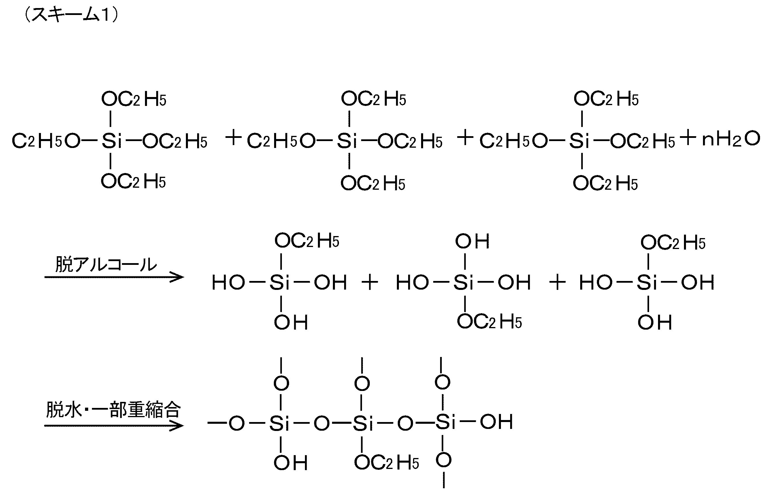
次に、シロキサンオリゴマーと炭化水素基含有トリアルコキシシランとの反応が開始する。炭化水素基含有トリアルコキシシランは、上述の「酸性ガス含有ガス処理用分離膜」の項目で説明したものを使用することができる。例えば、炭化水素基含有トリアルコキシシランの一例としてメチルトリエトキシシランを使用した場合、反応は下記のスキーム2のように進行すると考えられる。なお、このスキーム2は、反応の進行を表す一つのモデルであり、実際の分子構造をそのまま反映しているとは限らない。
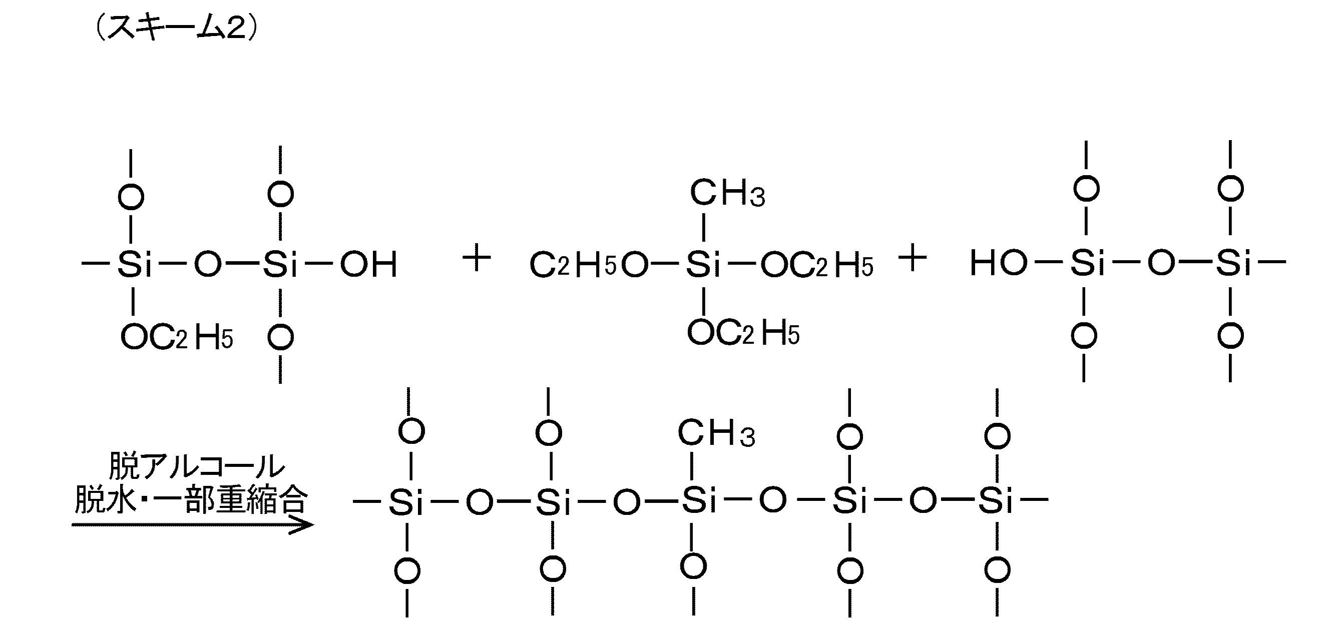
準備工程では、上記の第一混合液とは別に、テトラアルコキシシラン(A2)と炭化水素基含有トリアルコキシシラン(B2)との配合比率(A2/B2)が重量比で0/100~70/30に調整されたアルコキシシラン、酸触媒、水、及び有機溶媒を混合した第二混合液をさらに調製する。第二混合液は、後述の「第二塗布工程」において使用されるものである。アルコキシシラン(テトラアルコキシシラン及び炭化水素基含有トリアルコキシシラン)、酸触媒、水、並びに有機溶媒の夫々の配合量は、テトラアルコキシシラン及び炭化水素基含有トリアルコキシシランの合計量1モルに対して、酸触媒0.005~0.1モル、水0.017~3モル、有機溶媒5~60モルに調整することが好ましい。酸触媒の配合量が0.005モルより少ない場合、加水分解速度が小さくなり、分離膜の製造に要する時間が長くなる。酸触媒の配合量が0.1モルより多い場合、加水分解速度が過大となり、均一な分離膜が得られ難くなる。水の配合量は、第一混合液よりも少なく設定されるが、水の配合量が0.017モルより少ない場合、加水分解速度が小さくなり、後述のゾル-ゲル反応が十分に進行しない。水の配合量が3モルより多い場合、緻密で均一な分離膜が得られ難くなる。有機溶媒の配合量が5モルより少ない場合、第二混合液の濃度が高くなり、緻密で均一な分離膜が得られ難くなる。有機溶媒の配合量が60モルより多い場合、第二混合液の濃度が低くなり、混合液のコーティング回数(工程数)が増加して生産効率が低下する。酸触媒及び有機溶媒は、第一混合液と同様のものを使用することができる。第二混合液を調製する際、二酸化炭素と親和性を有する金属塩を配合することも可能である。金属塩の配合量は、上記の配合条件の場合、0.01~0.3モルに調整される。二酸化炭素と親和性を有する金属塩としては、上述の「酸性ガス含有ガス処理用分離膜」の項目で説明したものを使用することができる。金属塩を添加する場合は、ゾル-ゲル反応時にポリシロキサンに取り込まれた金属塩はポリシロキサン結合中に略均等に分散すると考えられる。
なお、第一混合液及び第二混合液を調製するにあたっては、第一混合液調製時の上記配合比率(A1/B1)が第二混合液調製時の上記配合比率(A2/B2)より大きくなるように、テトラアルコキシシラン及び炭化水素基含有トリアルコキシシランを配合する。このような配合とすれば、最終的に得られる分離膜は、分離層の方が中間層よりも炭化水素基含有トリアルコキシシランに由来する炭化水素基を多く含有することになるため、酸性ガスの分離性能と成膜性とのバランスが良好なものとなる。
第二混合液の反応は、上述のスキーム1及びスキーム2と同様である。第二混合液中で進行する加水分解反応を「第二加水分解反応」とする。ここで、第一加水分解反応と第二加水分解反応とを比較すると、第一混合液に含まれる水の量は第二混合液に含まれる水の量より多く設定されているため、第一加水分解反応は第二の加水分解反応より加水分解速度が大きいものとなる。加水分解速度が大きくなると、ゾル-ゲル反応によって得られるポリシロキサン網目構造体の高分子化が進行し、後述する無機多孔質支持体の表面を安定化させることができる。
以上のように準備工程が行われるが、第一混合液の調製においては、水を複数回に分けて混合することが好ましい。この場合、第一加水分解反応を確実に進行させることができるため、無機多孔質支持体の表面をより安定化させることができる。また、第一混合液及び第二混合液の調製においては、酸触媒を複数回に分けて混合したり、加水分解し易い炭化水素基含有トリアルコキシシランを最後に混合する等の工夫を行うことが好ましい。例えば、混合液のpHが常に0.8~2.5の範囲に収まるように、組成を調製する。この場合、混合液のpHが大きく変動しないため、炭化水素基含有トリアルコキシシランの加水分解が急激に進行せず、安定した状態でゾル-ゲル反応を進行させることができる。さらに、第一混合液の調製に使用する水の量をW1とし、第二混合液の調製に使用する水の量をW2としたとき、両者の比率(W1/W2)は、モル換算で10~20に設定されることが好ましい。この場合、後述する中間層がより安定化し、中間層の上に形成される分離層のガス選択性及びガス透過性を向上させることができる。
(b)第一塗布工程
第一塗布工程として、準備工程で得られた第一混合液(微細化されたポリシロキサン網目構造体の懸濁液)を無機多孔質支持体に塗布する。無機多孔質支持体に第一混合液を塗布する方法は、例えば、ディッピング法、スプレー法、スピン法等が挙げられる。これらのうち、ディッピング法は、無機多孔質支持体の表面に混合液を均等且つ容易に塗布できるため、好ましい塗布方法である。ディッピング法の具体的な手順について説明する。
先ず、無機多孔質支持体を第一混合液に浸漬する。浸漬時間は、無機多孔質支持体に第一混合液が十分に付着するように5秒~10分とすることが好ましい。浸漬時間が5秒より短いと十分な膜厚にならず、10分を超えると膜厚が大きくなり過ぎてしまう。次いで、第一混合液から無機多孔質支持体を引き上げる。引き上げ速度は、0.1~2mm/秒とすることが好ましい。引き上げ速度が0.1mm/秒より遅くなると膜厚が大きくなり過ぎてしまい、2mm/秒より速いと十分な膜厚にならない。次いで、引き上げた無機多孔質支持体を乾燥させる。乾燥条件は、15~40℃で0.5~3時間とすることが好ましい。乾燥時間が0.5時間未満では十分な乾燥ができず、3時間を超えても乾燥状態は殆ど変化しない。乾燥が終わると、無機多孔質支持体の表面(一部の微細孔の内面を含む)に微細化されたポリシロキサン網目構造体が付着したものが得られる。なお、無機多孔質支持体の浸漬、引き上げ、乾燥の一連の手順を複数回繰り返すことにより、無機多孔質支持体への微細化されたポリシロキサン網目構造体の付着量を増加させることができる。また、一連の手順を繰り返すことで、無機多孔質支持体に第一混合液を均一に塗布することができるため、最終的に得られる酸性ガス含有ガス処理用分離膜をより安定させることができる。
第一塗布工程として、準備工程で得られた第一混合液(微細化されたポリシロキサン網目構造体の懸濁液)を無機多孔質支持体に塗布する。無機多孔質支持体に第一混合液を塗布する方法は、例えば、ディッピング法、スプレー法、スピン法等が挙げられる。これらのうち、ディッピング法は、無機多孔質支持体の表面に混合液を均等且つ容易に塗布できるため、好ましい塗布方法である。ディッピング法の具体的な手順について説明する。
先ず、無機多孔質支持体を第一混合液に浸漬する。浸漬時間は、無機多孔質支持体に第一混合液が十分に付着するように5秒~10分とすることが好ましい。浸漬時間が5秒より短いと十分な膜厚にならず、10分を超えると膜厚が大きくなり過ぎてしまう。次いで、第一混合液から無機多孔質支持体を引き上げる。引き上げ速度は、0.1~2mm/秒とすることが好ましい。引き上げ速度が0.1mm/秒より遅くなると膜厚が大きくなり過ぎてしまい、2mm/秒より速いと十分な膜厚にならない。次いで、引き上げた無機多孔質支持体を乾燥させる。乾燥条件は、15~40℃で0.5~3時間とすることが好ましい。乾燥時間が0.5時間未満では十分な乾燥ができず、3時間を超えても乾燥状態は殆ど変化しない。乾燥が終わると、無機多孔質支持体の表面(一部の微細孔の内面を含む)に微細化されたポリシロキサン網目構造体が付着したものが得られる。なお、無機多孔質支持体の浸漬、引き上げ、乾燥の一連の手順を複数回繰り返すことにより、無機多孔質支持体への微細化されたポリシロキサン網目構造体の付着量を増加させることができる。また、一連の手順を繰り返すことで、無機多孔質支持体に第一混合液を均一に塗布することができるため、最終的に得られる酸性ガス含有ガス処理用分離膜をより安定させることができる。
(c)中間層形成工程
中間層形成工程として、第一塗布工程が完了した無機多孔質支持体を熱処理し、当該無機多孔質支持体の表面に微細化されたポリシロキサン網目構造体を固着又は融着させてポリシロキサン網目構造体を主材とした中間層を形成する。熱処理は、例えば、焼成器等の加熱手段が用いられる。熱処理の具体的な手順について説明する。
先ず、無機多孔質支持体を後述の熱処理温度に達するまで昇温する。昇温時間は、1~24時間が好ましい。昇温時間が1時間より短いと急激な温度変化により均一な膜が得られ難く、24時間より長いと長時間の加熱により膜が劣化する虞がある。昇温後、一定時間で熱処理(焼成)を行う。熱処理温度は、30~300℃が好ましく、50~200℃がより好ましい。熱処理温度が30℃より低いと十分な熱処理を行えないため緻密な膜が得られず、300℃より高いと高温の加熱により膜が劣化する虞がある。熱処理時間は、0.5~6時間が好ましい。熱処理時間が0.5時間より短いと十分な熱処理を行えないため緻密な膜が得られず、6時間より長いと長時間の加熱により膜が劣化する虞がある。熱処理が終わったら、無機多孔質支持体を室温まで冷却する。冷却時間は、5~10時間が好ましい。冷却時間が5時間より短いと急激な温度変化により膜に亀裂や剥離が発生する虞があり、10時間より長いと膜が劣化する虞がある。冷却後の無機多孔質支持体の表面(一部の微細孔の内面を含む)には中間層が形成される。中間層は、目付量が0.1~4.0mg/cm2に調整され、好ましくは0.5~2.0mg/cm2に調整される。なお、「中間層形成工程」の後、上述した「第一塗布工程」に戻り、第一塗布工程と中間層形成工程とをセットとして、これを複数回繰り返すと、無機多孔質支持体の表面に、より緻密で且つ均一な膜質の中間層を形成することができる。
中間層形成工程として、第一塗布工程が完了した無機多孔質支持体を熱処理し、当該無機多孔質支持体の表面に微細化されたポリシロキサン網目構造体を固着又は融着させてポリシロキサン網目構造体を主材とした中間層を形成する。熱処理は、例えば、焼成器等の加熱手段が用いられる。熱処理の具体的な手順について説明する。
先ず、無機多孔質支持体を後述の熱処理温度に達するまで昇温する。昇温時間は、1~24時間が好ましい。昇温時間が1時間より短いと急激な温度変化により均一な膜が得られ難く、24時間より長いと長時間の加熱により膜が劣化する虞がある。昇温後、一定時間で熱処理(焼成)を行う。熱処理温度は、30~300℃が好ましく、50~200℃がより好ましい。熱処理温度が30℃より低いと十分な熱処理を行えないため緻密な膜が得られず、300℃より高いと高温の加熱により膜が劣化する虞がある。熱処理時間は、0.5~6時間が好ましい。熱処理時間が0.5時間より短いと十分な熱処理を行えないため緻密な膜が得られず、6時間より長いと長時間の加熱により膜が劣化する虞がある。熱処理が終わったら、無機多孔質支持体を室温まで冷却する。冷却時間は、5~10時間が好ましい。冷却時間が5時間より短いと急激な温度変化により膜に亀裂や剥離が発生する虞があり、10時間より長いと膜が劣化する虞がある。冷却後の無機多孔質支持体の表面(一部の微細孔の内面を含む)には中間層が形成される。中間層は、目付量が0.1~4.0mg/cm2に調整され、好ましくは0.5~2.0mg/cm2に調整される。なお、「中間層形成工程」の後、上述した「第一塗布工程」に戻り、第一塗布工程と中間層形成工程とをセットとして、これを複数回繰り返すと、無機多孔質支持体の表面に、より緻密で且つ均一な膜質の中間層を形成することができる。
(d)第二塗布工程
第二塗布工程として、中間層形成工程によって中間層が形成された無機多孔質支持体に第二混合液(微細化されたポリシロキサン網目構造体の懸濁液)を塗布する。第二塗布工程で塗布される第二混合液は、中間層を介して無機多孔質支持体に塗布されるため、無機多孔質支持体への第二混合液の浸み込み量(無機多孔質支持体の表面から深さ方向にテトラアルコキシシラン又は炭化水素基含有トリアルコキシシランが浸み込む距離)を50μm以下に抑えることができる。従って、無機多孔質支持体の微細孔が過度に塞がれることがなく、後述の分離層形成工程により完成した酸性ガス含有ガス処理用分離膜に混合ガスを通過させた場合、ガス通過量(混合ガスの処理量)を維持することができる。また、無機多孔質支持体に塗布する中間層及び分離層の形成材料(ゾル)の塗布量を低減することができるため、酸性ガス含有ガス処理用分離膜の製造コストの削減にも寄与し得る。第二混合液を塗布する方法及び条件は、第一塗布工程と同様である。第二塗布工程においても、第二混合液への無機多孔質支持体の浸漬、引き上げ、乾燥の一連の手順を複数回繰り返すことにより、無機多孔質支持体への微細化されたポリシロキサン網目構造体の付着量を増加させることができる。また、一連の手順を繰り返すことで、無機多孔質支持体に第二混合液を均一に塗布することができるため、最終的に得られる酸性ガス含有ガス処理用分離膜の分離性能をより向上させることができる。
第二塗布工程として、中間層形成工程によって中間層が形成された無機多孔質支持体に第二混合液(微細化されたポリシロキサン網目構造体の懸濁液)を塗布する。第二塗布工程で塗布される第二混合液は、中間層を介して無機多孔質支持体に塗布されるため、無機多孔質支持体への第二混合液の浸み込み量(無機多孔質支持体の表面から深さ方向にテトラアルコキシシラン又は炭化水素基含有トリアルコキシシランが浸み込む距離)を50μm以下に抑えることができる。従って、無機多孔質支持体の微細孔が過度に塞がれることがなく、後述の分離層形成工程により完成した酸性ガス含有ガス処理用分離膜に混合ガスを通過させた場合、ガス通過量(混合ガスの処理量)を維持することができる。また、無機多孔質支持体に塗布する中間層及び分離層の形成材料(ゾル)の塗布量を低減することができるため、酸性ガス含有ガス処理用分離膜の製造コストの削減にも寄与し得る。第二混合液を塗布する方法及び条件は、第一塗布工程と同様である。第二塗布工程においても、第二混合液への無機多孔質支持体の浸漬、引き上げ、乾燥の一連の手順を複数回繰り返すことにより、無機多孔質支持体への微細化されたポリシロキサン網目構造体の付着量を増加させることができる。また、一連の手順を繰り返すことで、無機多孔質支持体に第二混合液を均一に塗布することができるため、最終的に得られる酸性ガス含有ガス処理用分離膜の分離性能をより向上させることができる。
(e)分離層形成工程
分離層形成工程として、第二塗布工程が完了した無機多孔質支持体を熱処理し、当該無機多孔質支持体の表面に微細化されたポリシロキサン網目構造体を固着又は融着させてポリシロキサン網目構造体を主材とした分離層を形成する。熱処理の方法及び条件は、中間層形成工程と同様である。分離層形成工程により、中間層の上に分離層が形成される。分離層は、目付量が0.1~3.0mg/cm2に調整され、好ましくは0.3~1.5mg/cm2に調整される。なお、「分離層形成工程」の後、上述した「第二塗布工程」に戻り、第二塗布工程と分離層形成工程とをセットとして、これを複数回繰り返すと、無機多孔質支持体の表面に、より緻密で且つ均一な膜質の分離層を形成することができる。
分離層形成工程として、第二塗布工程が完了した無機多孔質支持体を熱処理し、当該無機多孔質支持体の表面に微細化されたポリシロキサン網目構造体を固着又は融着させてポリシロキサン網目構造体を主材とした分離層を形成する。熱処理の方法及び条件は、中間層形成工程と同様である。分離層形成工程により、中間層の上に分離層が形成される。分離層は、目付量が0.1~3.0mg/cm2に調整され、好ましくは0.3~1.5mg/cm2に調整される。なお、「分離層形成工程」の後、上述した「第二塗布工程」に戻り、第二塗布工程と分離層形成工程とをセットとして、これを複数回繰り返すと、無機多孔質支持体の表面に、より緻密で且つ均一な膜質の分離層を形成することができる。
以上の工程(a)~(e)を実施することにより、中間層及び分離層を備えた本発明の酸性ガス含有ガス処理用分離膜が完成する。この分離膜は、ベースとなる無機多孔質支持体に、特定のガス(本実施形態の場合、二酸化炭素)を誘引するサイト(メチル基)を有する分離層が形成されたものである。分離層は、中間層を介して無機多孔質支持体の表面に形成されている。ここで、中間層に含まれるポリシロキサン網目構造体は、炭化水素基含有トリアルコキシシランに由来する炭化水素基を含有するため、一般的な網目構造体よりも柔軟性を有するものとなる。このため、中間層は、テトラアルコキシシランによってある程度の剛性を維持しながら、全体の柔軟性やフレキシブル性が向上したものとなる。中間層の柔軟性が向上すると、中間層の成膜性が向上する。これにより、中間層のひび割れや剥がれが防止され、無機多孔質支持体への分離層の原材料液の浸み込み量が低減される。原材料液の浸み込み量(浸み込む距離)は50μm以下であれば問題はないが、好ましくは、20μm以下である。この場合、分離層の厚みの増加が抑えられ、ガス透過性に優れた酸性ガス含有ガス処理用分離膜を得ることができる。
また、中間層及び分離層に夫々含まれるポリシロキサン網目構造体は、テトラアルコキシシランと炭化水素基含有トリアルコキシシランとの配合比率が異なるのみで、同じ系統の材料で構成されたものであるから、互いに対して高い親和性を有している。従って、中間層と分離層との間で界面剥離やひび割れ等が発生せず、両者は強固に密着し、安定な酸性ガス含有ガス処理用分離膜を構成することができる。
完成した酸性ガス含有ガス処理用分離膜に、二酸化炭素等の酸性ガスとメタンガスとを含有する混合ガスを通過させると、分離層の方が中間層よりも炭化水素基含有トリアルコキシシランに由来する炭化水素基を多く含有しているため、混合ガス中の酸性ガスが選択的に分離層に誘引され、そのまま分離膜を透過する。その結果、混合ガス中のメタンガス成分が濃縮され、高濃度のメタンガスを効率的に得ることができる。濃縮されたメタンガスは、都市ガスの原料や、燃料電池に使用する水素の原料に利用することができる。なお、分離層がメタンガスを誘引するサイト(エチル基以上の炭素数を有する炭化水素基)を有する場合は、二酸化炭素とメタンガスとを含む混合ガスを通過させると、分離層にメタンガスが選択的に誘引され、メタンガスは細孔をそのまま透過する。従って、この場合は、分離膜を透過したメタンガスを回収し、これを都市ガスの原料や、燃料電池に使用する水素の原料に利用することができる。
酸性ガス含有ガス処理用分離膜において、中間層におけるテトラアルコキシシラン(A1)と炭化水素基含有トリアルコキシシラン(B1)との配合比率(A1/B1)、及び分離層におけるテトラアルコキシシラン(A2)と炭化水素基含有トリアルコキシシラン(B2)との配合比率(A2/B2)を種々変更したものを作製し、各分離膜について、ガス分離性能確認試験を実施した。さらに、酸性ガス含有ガス処理用分離膜の構造を走査型電子顕微鏡(SEM)によって解析した。
すべての分離膜に共通で、無機多孔質支持体としてチューブラー構造を有するアルミナ系セラミックス管状体を使用した。中間層及び分離層の原材料は、テトラアルコキシシランとしてテトラエトキシシラン(信越化学工業株式会社製 信越シリコーンLS-2430)、炭化水素基含有トリアルコキシシランとしてメチルトリエトキシシラン(信越化学工業株式会社製 信越シリコーンLS-1890)、酸触媒として硝酸(和光純薬工業株式会社製 試薬特級 69.5%)、有機溶媒としてエタノール(和光純薬工業株式会社製 試薬特級 99.5%)を夫々使用した。
〔実施例1~6,比較例1~5,参考例1〕
<第一混合液の調製>
硝酸0.007g、エタノール36.31g、水35.47gの混合液を30分間攪拌し、次いでテトラエトキシシラン8.21gを添加して2時間攪拌することにより、中間層形成用アルコキシド溶液(第一混合液)のベース液を作製した。ベース液のpHは3.85であった。ベース液に含まれる各成分のモル濃度比率は、テトラエトキシシランを1とした場合、硝酸が0.003、エタノールが20、水が50である。このベース液40gにメチルトリエトキシシランを添加し、これを2.5時間攪拌して中間層形成用アルコキシド液(第一混合液)を調製した。メチルトリエトキシシランの添加量(含有量)は、第一混合液に含まれるすべてのアルコキシシラン中のメチルトリエトキシシランの割合が0.5~60重量%となるように設定した。従って、下記表1のとおり、テトラエトキシシラン(A1)とメチルトリエトキシシラン(B1)との配合比率(A1/B1)は、重量比で40/60~99.5/0.5となる。参考例1(0重量%)は、メチルトリエトキシシランを含まない従来品に相当する分離膜である。表1では、テトラエトキシシランを「TEOS」、メチルトリエトキシシランを「Me-TEOS」と表している。
<第一混合液の調製>
硝酸0.007g、エタノール36.31g、水35.47gの混合液を30分間攪拌し、次いでテトラエトキシシラン8.21gを添加して2時間攪拌することにより、中間層形成用アルコキシド溶液(第一混合液)のベース液を作製した。ベース液のpHは3.85であった。ベース液に含まれる各成分のモル濃度比率は、テトラエトキシシランを1とした場合、硝酸が0.003、エタノールが20、水が50である。このベース液40gにメチルトリエトキシシランを添加し、これを2.5時間攪拌して中間層形成用アルコキシド液(第一混合液)を調製した。メチルトリエトキシシランの添加量(含有量)は、第一混合液に含まれるすべてのアルコキシシラン中のメチルトリエトキシシランの割合が0.5~60重量%となるように設定した。従って、下記表1のとおり、テトラエトキシシラン(A1)とメチルトリエトキシシラン(B1)との配合比率(A1/B1)は、重量比で40/60~99.5/0.5となる。参考例1(0重量%)は、メチルトリエトキシシランを含まない従来品に相当する分離膜である。表1では、テトラエトキシシランを「TEOS」、メチルトリエトキシシランを「Me-TEOS」と表している。
<第二混合液の調製>
硝酸0.04g、エタノール63.16g、水2.47gの混合液を30分間攪拌し、次いでテトラエトキシシラン8.57gを添加して1時間攪拌し、次いでメチルトリエトキシシラン4.89gを添加して2.5時間攪拌し、次いで硝酸マグネシウム六水和物0.88gを添加して2時間攪拌することにより、分離層形成用アルコキシド溶液(第二混合液)を調製した。第二混合液のpHは1.59であった。第二混合液に含まれる各成分のモル濃度比率は、テトラエトキシシラン及びメチルトリエトキシシランの合計配合量を1とした場合、硝酸が0.01、エタノールが20、水が2、硝酸マグネシウム六水和物が0.05である。第二混合液に含まれるすべてのアルコキシシラン中のメチルトリエトキシシランの割合は、すべて一定の36重量%に設定した。従って、下記表1のとおり、テトラエトキシシラン(A2)とメチルトリエトキシシラン(B2)との配合比率(A2/B2)は、重量比で64/36となる。
硝酸0.04g、エタノール63.16g、水2.47gの混合液を30分間攪拌し、次いでテトラエトキシシラン8.57gを添加して1時間攪拌し、次いでメチルトリエトキシシラン4.89gを添加して2.5時間攪拌し、次いで硝酸マグネシウム六水和物0.88gを添加して2時間攪拌することにより、分離層形成用アルコキシド溶液(第二混合液)を調製した。第二混合液のpHは1.59であった。第二混合液に含まれる各成分のモル濃度比率は、テトラエトキシシラン及びメチルトリエトキシシランの合計配合量を1とした場合、硝酸が0.01、エタノールが20、水が2、硝酸マグネシウム六水和物が0.05である。第二混合液に含まれるすべてのアルコキシシラン中のメチルトリエトキシシランの割合は、すべて一定の36重量%に設定した。従って、下記表1のとおり、テトラエトキシシラン(A2)とメチルトリエトキシシラン(B2)との配合比率(A2/B2)は、重量比で64/36となる。
<中間層及び分離層の形成>
チューブラー構造を有するアルミナ系セラミックス管状体の表面に第一混合液をディッピング法によって塗布した。ディッピング法の引き上げ速度は5mm/sとし、引き上げ後は室温で1時間乾燥させた。第一混合液の塗布及び乾燥を2回繰り返した後、焼成器で熱処理を行った。熱処理条件は、室温(25℃)から150℃まで5時間かけて加熱し、150℃で2時間保持し、25℃まで5時間かけて冷却した。上記の作業(コーティング)を3回繰り返し、管状体の表面に中間層を形成した。次に、中間層を形成した管状体の表面に第二混合液をディッピング法によって塗布した。ディッピング法の引き上げ速度は5mm/sとし、引き上げ後は室温で1時間乾燥させた。第二混合液の塗布及び乾燥を2回繰り返した後、焼成器で熱処理を行った。熱処理条件は、室温(25℃)から150℃まで5時間かけて加熱し、150℃で2時間保持し、25℃まで5時間かけて冷却した。上記の作業(コーティング)を2回繰り返し、中間層の上に分離層を形成した。上記の層形成工程において、実施例1~6における中間層及び分離層はいずれも成膜性に問題はなかった。目付量に関しては、下記表1のとおり、実施例1~6はいずれも分離層の目付量が中間層の目付量より小さくなり、分離層の厚みの増加が抑えられたものとなっていた。中間層の目付量に関しても、参考例1として示した従来品と同等の目付量となり、全体として厚みが抑えられた酸性ガス含有ガス処理用分離膜が得られた。
チューブラー構造を有するアルミナ系セラミックス管状体の表面に第一混合液をディッピング法によって塗布した。ディッピング法の引き上げ速度は5mm/sとし、引き上げ後は室温で1時間乾燥させた。第一混合液の塗布及び乾燥を2回繰り返した後、焼成器で熱処理を行った。熱処理条件は、室温(25℃)から150℃まで5時間かけて加熱し、150℃で2時間保持し、25℃まで5時間かけて冷却した。上記の作業(コーティング)を3回繰り返し、管状体の表面に中間層を形成した。次に、中間層を形成した管状体の表面に第二混合液をディッピング法によって塗布した。ディッピング法の引き上げ速度は5mm/sとし、引き上げ後は室温で1時間乾燥させた。第二混合液の塗布及び乾燥を2回繰り返した後、焼成器で熱処理を行った。熱処理条件は、室温(25℃)から150℃まで5時間かけて加熱し、150℃で2時間保持し、25℃まで5時間かけて冷却した。上記の作業(コーティング)を2回繰り返し、中間層の上に分離層を形成した。上記の層形成工程において、実施例1~6における中間層及び分離層はいずれも成膜性に問題はなかった。目付量に関しては、下記表1のとおり、実施例1~6はいずれも分離層の目付量が中間層の目付量より小さくなり、分離層の厚みの増加が抑えられたものとなっていた。中間層の目付量に関しても、参考例1として示した従来品と同等の目付量となり、全体として厚みが抑えられた酸性ガス含有ガス処理用分離膜が得られた。
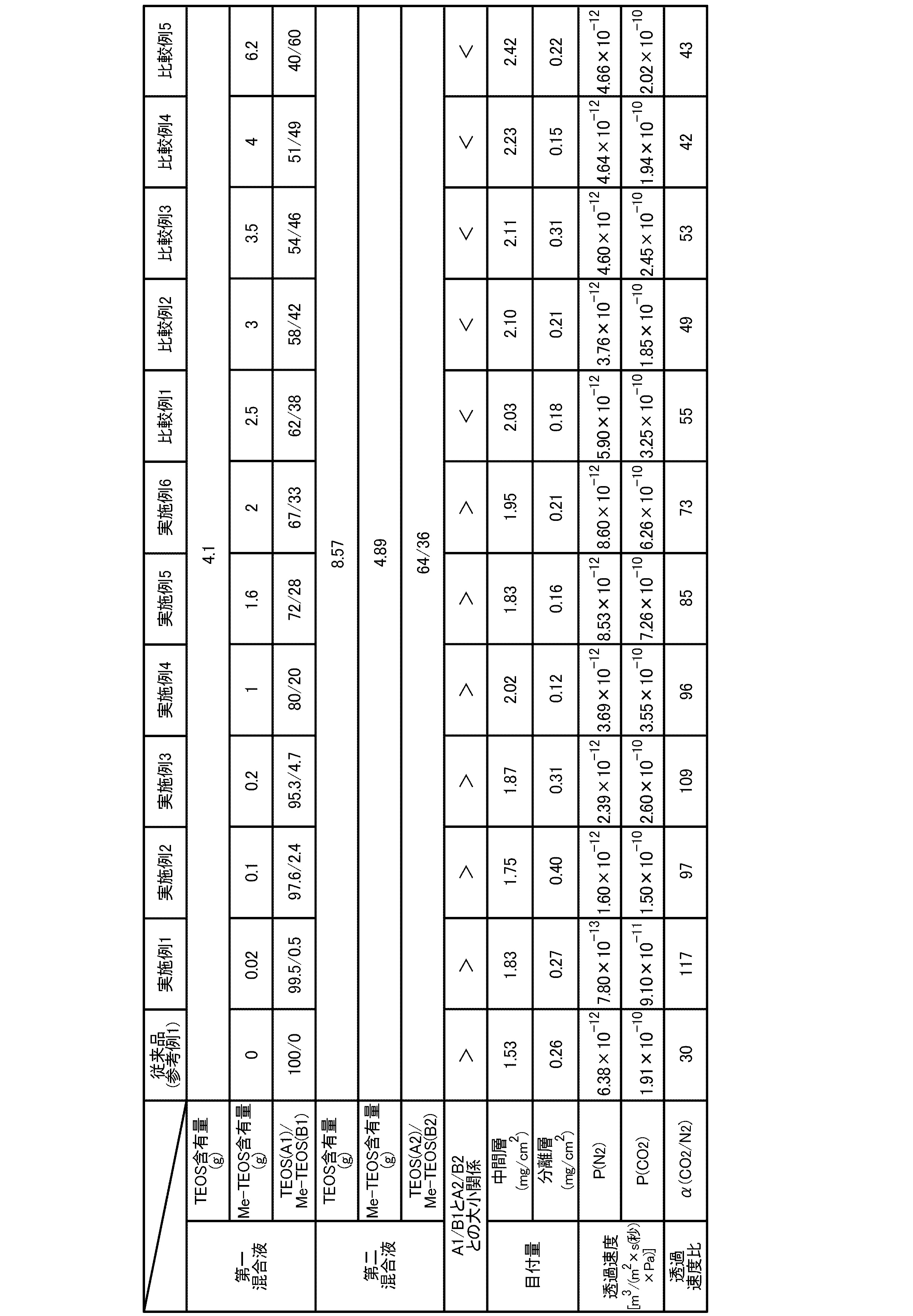
<分離性能確認試験>
上記の手順により作製した各分離膜について、二酸化炭素の分離性能に関する確認試験を行った。この確認試験では、分離膜に窒素を透過させたときの気体透過速度〔P(N2)〕、及び同じ分離膜に二酸化炭素を透過させたときの気体透過速度〔P(CO2)〕を測定した。ここで、窒素の気体分子径は3.64Åであり、二酸化炭素の気体分子径は3.3Åである。このため、窒素よりも気体分子径が小さい二酸化炭素は分離膜を透過し易い。従って、このような気体によって異なる性質を利用し、さらに膜の構成を適切に設定すれば、二酸化炭素を含有する混合ガスから二酸化炭素を分離することが可能となる。なお、この確認試験では、分離膜にメタンガスを透過させたときの気体透過速度〔P(CH3)〕の測定は行っていないが、メタンガスの気体分子径(3.8Å)は窒素の気体分子径(3.64Å)よりも若干大きいため、本発明の分離膜によって二酸化炭素と窒素との分離が可能であることが確認できれば、二酸化炭素とメタンガスとの分離も可能であると推定される。
上記の手順により作製した各分離膜について、二酸化炭素の分離性能に関する確認試験を行った。この確認試験では、分離膜に窒素を透過させたときの気体透過速度〔P(N2)〕、及び同じ分離膜に二酸化炭素を透過させたときの気体透過速度〔P(CO2)〕を測定した。ここで、窒素の気体分子径は3.64Åであり、二酸化炭素の気体分子径は3.3Åである。このため、窒素よりも気体分子径が小さい二酸化炭素は分離膜を透過し易い。従って、このような気体によって異なる性質を利用し、さらに膜の構成を適切に設定すれば、二酸化炭素を含有する混合ガスから二酸化炭素を分離することが可能となる。なお、この確認試験では、分離膜にメタンガスを透過させたときの気体透過速度〔P(CH3)〕の測定は行っていないが、メタンガスの気体分子径(3.8Å)は窒素の気体分子径(3.64Å)よりも若干大きいため、本発明の分離膜によって二酸化炭素と窒素との分離が可能であることが確認できれば、二酸化炭素とメタンガスとの分離も可能であると推定される。
図1は、分離性能確認試験に使用した気体透過速度測定装置10の概略構成図である。気体透過速度測定装置10は、ガスシリンダー1、圧力ゲージ2、チャンバー3、及び質量流量計4を備える。分離膜5は、チャンバー3の内部に設置される。
測定ガスである二酸化炭素又は窒素をガスシリンダー1に予め充填しておく。ここでは、二酸化炭素をガスシリンダー1に充填したものとして説明する。ガスシリンダー1から排出された二酸化炭素は、圧力ゲージ2によって圧力が調整され、下流側のチャンバー3に供給される。本確認試験では、二酸化炭素の供給圧を室温で0.1MPaに調整した。管状体である分離膜5は、一端(先端側)5aが封止され、他端(基端側)5bに耐熱ガラス管6が接続される。耐熱ガラス管6は、コーニング社製のパイレックス(登録商標)管(外径8mm、内径6mm、長さ10mm)を使用した。ただし、耐熱ガラス管6の一端側は、分離膜5(内径7mm)に内挿できるように、外径が7mm以下に縮径加工されている。分離膜5と耐熱ガラス管6との接続箇所は、接着剤(セメダイン株式会社製の接着剤「セメダイン(登録商標)C」)で接着し、さらにエポキシ樹脂(ナガセケムテックス株式会社製の二液性エポキシ系接着剤「AV138」及び「HV998」)によってシールした。チャンバー3が二酸化炭素で充満されると、二酸化炭素は管状体である分離膜5の表面から管内に透過し、耐熱ガラス管6を通過して質量流量計4に流入する。質量流量計4には、コフロック社製の熱式質量流量計(マスフローメーター「5410」)を使用した。測定条件は、流量レンジを10mL/分、フルスケール(FS)最大流量に対する精度は±1%(20℃)とした。質量流量計4で測定した二酸化炭素の流量〔mL/min〕から、二酸化炭素の気体透過速度〔P(CO2)〕(m3/(m2×s(秒)×Pa))を算出した。窒素についても上記と同様の手順により気体透過速度〔P(N2)〕(m3/(m2×s(秒)×Pa))を算出した。そして、二酸化炭素の気体透過速度〔P(CO2)〕と窒素の気体透過速度〔P(N2)〕との比率である透過速度比〔α(CO2/N2)〕から二酸化炭素の分離性能を評価した。分離性能確認試験の結果を先に説明した表1中に併せて示す。
テトラエトキシシラン(A1)とメチルトリエトキシシラン(B1)との配合比率(A1/B1)が、テトラエトキシシラン(A2)とメチルトリエトキシシラン(B2)との配合比率(A2/B2)より大きく設定されている実施例1~6の分離膜は、二酸化炭素と窒素との透過速度比〔α(CO2/N2)〕が大きくなり、二酸化炭素の分離性能が優れていた。これに対し、上記配合比率(A1/B1)が上記配合比率(A2/B2)より小さい比較例1~5の分離膜は、透過速度比〔α(CO2/N2)〕が小さくなり、実用レベルの二酸化炭素の分離性能は達成されなかった。ちなみに、中間層にメチルトリエトキシシランを含まない参考例1についても、二酸化炭素の分離性能は不十分であった。
〔実施例7~9〕
<第一混合液の調製条件の影響>
次に、第一混合液の調製条件を変更した場合、酸性ガス含有ガス処理用分離膜の成膜性や分離性能に及ぼされる影響について検討した。下記表2の実施例7~9の第一混合液は、実質的に表1の実施例5の第一混合液と同様の組成を有するものであるが、水の添加条件及び攪拌条件を変更している。表2中の「水」の欄にあるカッコ内の数値(モル)は、テトラエトキシシランを1とした場合の水のモル濃度比率である。実施例7~9において、第一混合液に含まれるすべてのアルコキシシラン中のメチルトリエトキシシランの割合は、すべて一定の28重量%に設定した。すなわち、テトラエトキシシラン(A1)とメチルトリエトキシシラン(B1)との配合比率(A1/B1)は、72/28である。また、第二混合液に含まれるすべてのアルコキシシラン中のメチルトリエトキシシランの割合は、すべて一定の36重量%に設定した。すなわち、テトラエトキシシラン(A2)とメチルトリエトキシシラン(B2)との配合比率(A2/B2)は、64/36である。
<第一混合液の調製条件の影響>
次に、第一混合液の調製条件を変更した場合、酸性ガス含有ガス処理用分離膜の成膜性や分離性能に及ぼされる影響について検討した。下記表2の実施例7~9の第一混合液は、実質的に表1の実施例5の第一混合液と同様の組成を有するものであるが、水の添加条件及び攪拌条件を変更している。表2中の「水」の欄にあるカッコ内の数値(モル)は、テトラエトキシシランを1とした場合の水のモル濃度比率である。実施例7~9において、第一混合液に含まれるすべてのアルコキシシラン中のメチルトリエトキシシランの割合は、すべて一定の28重量%に設定した。すなわち、テトラエトキシシラン(A1)とメチルトリエトキシシラン(B1)との配合比率(A1/B1)は、72/28である。また、第二混合液に含まれるすべてのアルコキシシラン中のメチルトリエトキシシランの割合は、すべて一定の36重量%に設定した。すなわち、テトラエトキシシラン(A2)とメチルトリエトキシシラン(B2)との配合比率(A2/B2)は、64/36である。
実施例7では、硝酸0.0037g、エタノール22.7g、水22.17gの混合液を30分間攪拌し、次いでテトラエトキシシラン5.13gを添加して2時間攪拌し、さらにメチルトリエトキシシラン2gを添加して2.5時間攪拌することにより、第一混合液を作製した。実施例7は、実施例5と同様の条件で調製したものである。
実施例8では、硝酸0.0037g、エタノール22.7g、水0.89gの混合液を30分間攪拌し、次いでテトラエトキシシラン5.13gを添加して2時間攪拌し、次いでメチルトリエトキシシラン2gを添加して2.5時間攪拌し、さらに水21.28gを添加して2時間攪拌することにより、第一混合液を作製した。実施例8は、実施例7に対して水の添加を2回に分割して調製したものである。
実施例9では、硝酸0.0037g、エタノール22.7g、水0.89gの混合液を30分間攪拌し、次いでテトラエトキシシラン5.13gを添加して1時間攪拌し、次いでメチルトリエトキシシラン2gを添加して2.5時間攪拌し、さらに水21.28gを添加して2時間攪拌することにより、第一混合液を作製した(実施例9)。実施例9は、実施例8に対してテトラエトキシシランを添加した後の攪拌時間を1/2の1時間に短縮して調製したものである。

実施例7~9においても、実施例1~6と同様に、中間層及び分離層はいずれも成膜性に問題はなかった。目付量に関しては、いずれも分離層の目付量が中間層の目付量より小さくなり、分離層の厚みの増加が抑えられたものとなっていた。その結果、全体として厚みが抑えられた酸性ガス含有ガス処理用分離膜が得られた。分離膜の性能に関しては、二酸化炭素と窒素との透過速度比〔α(CO2/N2)〕は十分に大きく、二酸化炭素の分離性能が実用レベルに達していることが確認された。特に、水の添加を分割した実施例8は、実施例7よりも分離性能が良好な結果となり、攪拌時間を短縮した実施例9は、実施例8よりもさらに良好な結果となった。
〔実施例10~11,比較例6~8〕
<炭化水素基含有トリアルコキシシランの含有量の影響>
次に、第一混合液に含まれるすべてのアルコキシシラン中のメチルトリエトキシシランの含有量を大きく変化させた場合、酸性ガス含有ガス処理用分離膜の成膜性や分離性能に及ぼされる影響について検討した。下記表3の実施例10~11及び比較例6~7は、テトラエトキシシランとメチルトリエトキシシランとの合計量を1モルとし、第一混合液におけるすべてのアルコキシシラン中のメチルトリエトキシシランの割合を60~80重量%に調整したものである。比較例8は、テトラエトキシシランとメチルトリエトキシシランとの合計量を1モルとし、第一混合液におけるすべてのアルコキシシラン中のメチルトリエトキシシランの割合を0.01重量%に調整したものである。実施例10~11及び比較例6~8において、第一混合液及び第二混合液の調製手順、並びに支持体表面への中間層及び分離層の形成条件は、実施例1~6と同様である。
<炭化水素基含有トリアルコキシシランの含有量の影響>
次に、第一混合液に含まれるすべてのアルコキシシラン中のメチルトリエトキシシランの含有量を大きく変化させた場合、酸性ガス含有ガス処理用分離膜の成膜性や分離性能に及ぼされる影響について検討した。下記表3の実施例10~11及び比較例6~7は、テトラエトキシシランとメチルトリエトキシシランとの合計量を1モルとし、第一混合液におけるすべてのアルコキシシラン中のメチルトリエトキシシランの割合を60~80重量%に調整したものである。比較例8は、テトラエトキシシランとメチルトリエトキシシランとの合計量を1モルとし、第一混合液におけるすべてのアルコキシシラン中のメチルトリエトキシシランの割合を0.01重量%に調整したものである。実施例10~11及び比較例6~8において、第一混合液及び第二混合液の調製手順、並びに支持体表面への中間層及び分離層の形成条件は、実施例1~6と同様である。
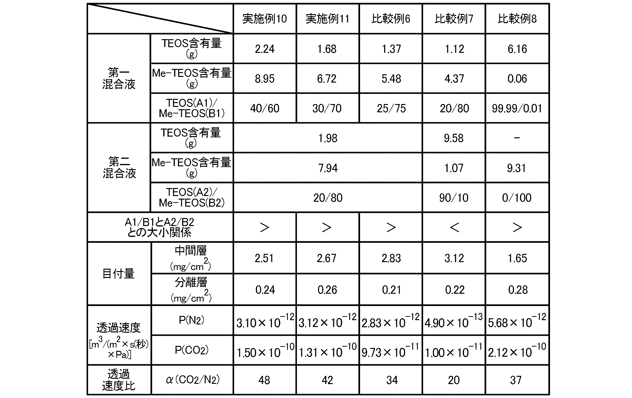
実施例10~11においても、実施例1~6と同様に、中間層及び分離層はいずれも成膜性に問題はなかった。目付量に関しては、いずれも分離層の目付量が中間層の目付量より小さくなり、分離層の厚みの増加が抑えられたものとなっていた。その結果、全体として厚みが抑えられた酸性ガス含有ガス処理用分離膜が得られた。分離膜の性能に関しては、二酸化炭素と窒素との透過速度比〔α(CO2/N2)〕は実施例1~9よりも若干小さくなったが、比較例6と比べると良好な結果が得られており、第一混合液に含まれるすべてのアルコキシシラン中のメチルトリエトキシシランの含有量を70%以下とすれば、実用レベルでの使用可能性が示唆されるものであった。比較例7の分離膜は、テトラエトキシシラン(A1)とメチルトリエトキシシラン(B1)との配合比率(A1/B1)が、テトラエトキシシラン(A2)とメチルトリエトキシシラン(B2)との配合比率(A2/B2)より小さいため、中間層の目付量が大きくなり、中間層の膜厚が増加した。その結果、透過速度比〔α(CO2/N2)〕が小さくなり、二酸化炭素の分離性能は実施例10~11の分離膜の半分にも満たないものであった。比較例8の分離膜は、第一混合液におけるすべてのアルコキシシラン中のメチルトリエトキシシランの含有量が極端に小さいため、中間層の成膜性が悪くなり、二酸化炭素の分離性能が劣る結果となった。
<中間層の構造評価>
本発明の酸性ガス含有ガス処理用分離膜について、その断面を走査型電子顕微鏡(SEM)によって観察し、表面から内部方向にSi成分の含有量をライン分析することで、無機多孔質支持体への第一混合液(中間層)/第二混合液(分離層)の浸み込み状態を評価した。
本発明の酸性ガス含有ガス処理用分離膜について、その断面を走査型電子顕微鏡(SEM)によって観察し、表面から内部方向にSi成分の含有量をライン分析することで、無機多孔質支持体への第一混合液(中間層)/第二混合液(分離層)の浸み込み状態を評価した。
図2は、第一混合液中の水の添加量を変えて作製した酸性ガス含有ガス処理用分離膜のSi分布を示すグラフである。(a)は、水の添加量をテトラエトキシシランの添加量の10倍(モル濃度比率)にした試験体であり、(b)は、水の添加量をテトラエトキシシランの添加量の50倍(モル濃度比率)にした試験体である。水の添加量が多くなると、Si分布のピーク形状がシャープになり、無機多孔質支持体への混合液の浸み込み深さが浅くなることが判明した。このことから、水が多く存在する条件下で加水分解反応を伴うゾル-ゲル反応を進行させると、加水分解反応が確実に進行してポリシロキサン網目構造体が高分子化し、無機多孔質支持体の表面付近に留まって第二混合液が浸み込み難い構造が得られるものと考えられる。ちなみに、無機多孔質支持体の表面に中間層を形成せずに分離層を直接形成したものは、(c)に示すように、Si分布のピーク形状がブロードになり、浸み込み深さも大きくなった。
図3は、第一混合液中の水の添加条件を変えて作製した酸性ガス含有ガス処理用分離膜のSi分布を示すグラフである。(a)は、水を一度に添加した試験体であり、(b)は、水を二回に分割して添加した試験体である。水を二回に分割して添加すると、Si分布のピーク形状がよりシャープになり、無機多孔質支持体への混合液の浸み込み深さがより浅くなることが判明した。このことから、第一混合液を調製する際に水を複数回に分けて混合すると、加水分解反応を伴うゾル-ゲル反応が穏やかに進行し、第一段階として先ずはテトラエトキシシラン及びメチルトリエトキシシランが鎖状にポリマー化し、次いで、第二段階としてポリマー鎖どうしが結合してポリシロキサン網目構造体がさらに肥大化するものと考えられる。その結果、無機多孔質支持体に対して第二混合液がより浸み込み難くなるものと考えられる。
本発明の酸性ガス含有ガス処理用分離膜、及びその製造方法は、都市ガスの製造設備、燃料電池への水素供給設備、工場排ガスの浄化設備、及び液化炭酸ガス製造設備等において利用可能である。また、地球温暖化対策として検討されているCCSにおいても利用可能である。
1 ガスシリンダー
2 圧力ゲージ
3 チャンバー
4 質量流量計
5 分離膜
6 耐熱ガラス管
10 気体透過速度測定装置
2 圧力ゲージ
3 チャンバー
4 質量流量計
5 分離膜
6 耐熱ガラス管
10 気体透過速度測定装置
Claims (10)
- 無機多孔質支持体の上に中間層と分離層とを積層してなる酸性ガス含有ガス処理用分離膜であって、
前記中間層は、テトラアルコキシシラン(A1)と炭化水素基含有トリアルコキシシラン(B1)との配合比率(A1/B1)が重量比で30/70~99.9/0.1に調整されたアルコキシシランのゾル-ゲル反応によって得られるポリシロキサン網目構造体を含み、
前記分離層は、テトラアルコキシシラン(A2)と炭化水素基含有トリアルコキシシラン(B2)との配合比率(A2/B2)が重量比で0/100~70/30に調整されたアルコキシシランのゾル-ゲル反応によって得られるポリシロキサン網目構造体を含み、
前記配合比率(A1/B1)は、前記配合比率(A2/B2)より大きく設定されている酸性ガス含有ガス処理用分離膜。 - 前記テトラアルコキシシランは、テトラメトキシシラン又はテトラエトキシシランであり、
前記炭化水素基含有トリアルコキシシランは、トリメトキシシラン又はトリエトキシシランのSi原子に炭素数1~6のアルキル基又はフェニル基が結合したものである請求項1に記載の酸性ガス含有ガス処理用分離膜。 - 前記分離層に、酸性ガスと親和性を有する金属塩を添加してある請求項1又は2に記載の酸性ガス含有ガス処理用分離膜。
- 前記金属塩は、Li、Na、K、Cs、Mg、Ca、Ni、Fe、及びAlからなる群から選択される少なくとも一種の金属の酢酸塩、硝酸塩、炭酸塩、ホウ酸塩、又はリン酸塩である請求項3に記載の酸性ガス含有ガス処理用分離膜。
- 前記中間層の目付量は、0.1~4.0mg/cm2であり、
前記分離層の目付量は、0.1~3.0mg/cm2である請求項1~4の何れか一項に記載の酸性ガス含有ガス処理用分離膜。 - 前記無機多孔質支持体は、4~200nmの微細孔を有する請求項1~5の何れか一項に記載の酸性ガス含有ガス処理用分離膜。
- 前記無機多孔質支持体の表面から深さ方向に前記アルコキシシランが浸み込む距離は、50μm以下である請求項1~6の何れか一項に記載の酸性ガス含有ガス処理用分離膜。
- (a)テトラアルコキシシラン(A1)と炭化水素基含有トリアルコキシシラン(B1)との配合比率(A1/B1)が重量比で30/70~99.9/0.1に調整されたアルコキシシラン、酸触媒、水、及び有機溶媒を混合した第一混合液、並びにテトラアルコキシシラン(A2)と炭化水素基含有トリアルコキシシラン(B2)との配合比率(A2/B2)が重量比で0/100~70/30に調整されたアルコキシシラン、酸触媒、水、及び有機溶媒を混合した第二混合液(ここで、前記配合比率(A1/B1)は、前記配合比率(A2/B2)より大きく設定されている)を調製する準備工程と、
(b)前記第一混合液を無機多孔質支持体の表面に塗布する第一塗布工程と、
(c)前記第一塗布工程が完了した無機多孔質支持体を熱処理し、当該無機多孔質支持体の表面にポリシロキサン網目構造体を含む中間層を形成する中間層形成工程と、
(d)前記第二混合液を前記中間層の上に塗布する第二塗布工程と、
(e)前記第二塗布工程が完了した無機多孔質支持体を熱処理し、前記中間層の上にポリシロキサン網目構造体を含む分離層を形成する分離層形成工程と、
を包含する酸性ガス含有ガス処理用分離膜の製造方法。 - 前記準備工程において、前記第一混合液の調製に使用する水の量(W1)と、前記第二混合液の調製に使用する水の量(W2)との比率(W1/W2)が、モル換算で10~20に設定される請求項8に記載の酸性ガス含有ガス処理用分離膜の製造方法。
- 前記準備工程において、前記第一混合液を調製する際、水を複数回に分けて混合する請求項8又は9に記載の酸性ガス含有ガス処理用分離膜の製造方法。
Priority Applications (1)
| Application Number | Priority Date | Filing Date | Title |
|---|---|---|---|
| JP2017507570A JPWO2016152280A1 (ja) | 2015-03-23 | 2016-02-08 | 酸性ガス含有ガス処理用分離膜、及び酸性ガス含有ガス処理用分離膜の製造方法 |
Applications Claiming Priority (2)
| Application Number | Priority Date | Filing Date | Title |
|---|---|---|---|
| JP2015059493 | 2015-03-23 | ||
| JP2015-059493 | 2015-03-23 |
Publications (1)
| Publication Number | Publication Date |
|---|---|
| WO2016152280A1 true WO2016152280A1 (ja) | 2016-09-29 |
Family
ID=56979070
Family Applications (1)
| Application Number | Title | Priority Date | Filing Date |
|---|---|---|---|
| PCT/JP2016/053625 Ceased WO2016152280A1 (ja) | 2015-03-23 | 2016-02-08 | 酸性ガス含有ガス処理用分離膜、及び酸性ガス含有ガス処理用分離膜の製造方法 |
Country Status (2)
| Country | Link |
|---|---|
| JP (1) | JPWO2016152280A1 (ja) |
| WO (1) | WO2016152280A1 (ja) |
Citations (5)
| Publication number | Priority date | Publication date | Assignee | Title |
|---|---|---|---|---|
| JPH10249175A (ja) * | 1997-03-12 | 1998-09-22 | Kyocera Corp | 多孔質分離膜及びその製造方法 |
| US6797206B1 (en) * | 1998-05-28 | 2004-09-28 | Stichting Energieonderzoek Centrum Nederland | Process of producing a microporous hydrophobic inorganic membrane |
| JP2012236189A (ja) * | 2011-04-26 | 2012-12-06 | Toyo Tire & Rubber Co Ltd | メタン分離膜および二酸化炭素分離膜、並びにそれらの製造方法 |
| WO2014080670A1 (ja) * | 2012-11-21 | 2014-05-30 | 東洋ゴム工業株式会社 | 酸性ガス含有ガス処理用分離膜及びその製造方法、酸性ガス又はメタンガスの分離方法、並びに酸性ガス又はメタンガスの製造方法 |
| WO2015141576A1 (ja) * | 2014-03-18 | 2015-09-24 | 東洋ゴム工業株式会社 | 酸性ガス含有ガス処理用分離膜、及び酸性ガス含有ガス処理用分離膜の製造方法 |
-
2016
- 2016-02-08 WO PCT/JP2016/053625 patent/WO2016152280A1/ja not_active Ceased
- 2016-02-08 JP JP2017507570A patent/JPWO2016152280A1/ja active Pending
Patent Citations (5)
| Publication number | Priority date | Publication date | Assignee | Title |
|---|---|---|---|---|
| JPH10249175A (ja) * | 1997-03-12 | 1998-09-22 | Kyocera Corp | 多孔質分離膜及びその製造方法 |
| US6797206B1 (en) * | 1998-05-28 | 2004-09-28 | Stichting Energieonderzoek Centrum Nederland | Process of producing a microporous hydrophobic inorganic membrane |
| JP2012236189A (ja) * | 2011-04-26 | 2012-12-06 | Toyo Tire & Rubber Co Ltd | メタン分離膜および二酸化炭素分離膜、並びにそれらの製造方法 |
| WO2014080670A1 (ja) * | 2012-11-21 | 2014-05-30 | 東洋ゴム工業株式会社 | 酸性ガス含有ガス処理用分離膜及びその製造方法、酸性ガス又はメタンガスの分離方法、並びに酸性ガス又はメタンガスの製造方法 |
| WO2015141576A1 (ja) * | 2014-03-18 | 2015-09-24 | 東洋ゴム工業株式会社 | 酸性ガス含有ガス処理用分離膜、及び酸性ガス含有ガス処理用分離膜の製造方法 |
Also Published As
| Publication number | Publication date |
|---|---|
| JPWO2016152280A1 (ja) | 2017-11-02 |
Similar Documents
| Publication | Publication Date | Title |
|---|---|---|
| JP6253764B2 (ja) | 酸性ガス含有ガス処理用分離膜、及び酸性ガス含有ガス処理用分離膜の製造方法 | |
| JP6196236B2 (ja) | ガス処理用分離膜及びその製造方法、二酸化炭素又はメタンガスの分離方法、並びに二酸化炭素又はメタンガスの製造方法 | |
| JP5882820B2 (ja) | メタン分離膜および二酸化炭素分離膜、並びにそれらの製造方法 | |
| JP6196178B2 (ja) | 酸性ガス含有ガス処理用分離膜、及び酸性ガス含有ガス処理用分離膜の製造方法 | |
| JP2016144798A (ja) | 酸素富化膜、及び酸素富化膜の製造方法 | |
| JP2009520594A (ja) | 三価元素を添加したシリカ系微孔質シリカ層を含むガス分離膜 | |
| JP2019042681A (ja) | 酸性ガス含有ガス処理用分離膜 | |
| JP2017127804A (ja) | 酸性ガス含有ガス処理用分離膜の製造方法 | |
| JP6457659B2 (ja) | 酸性ガス含有ガス処理用分離膜、及び酸性ガス含有ガス処理用分離膜の製造方法 | |
| JP6232061B2 (ja) | 酸性ガス含有ガス処理用分離膜、及び酸性ガス含有ガス処理用分離膜の製造方法 | |
| JPWO2016152280A1 (ja) | 酸性ガス含有ガス処理用分離膜、及び酸性ガス含有ガス処理用分離膜の製造方法 | |
| JP2018103092A (ja) | 酸性ガス含有ガス処理用分離膜の製造方法 | |
| JP2018008188A (ja) | ガス分離装置、及びガス分離方法 | |
| JP2018008189A (ja) | ガス分離装置、及びガス分離方法 |
Legal Events
| Date | Code | Title | Description |
|---|---|---|---|
| 121 | Ep: the epo has been informed by wipo that ep was designated in this application |
Ref document number: 16768183 Country of ref document: EP Kind code of ref document: A1 |
|
| ENP | Entry into the national phase |
Ref document number: 2017507570 Country of ref document: JP Kind code of ref document: A |
|
| NENP | Non-entry into the national phase |
Ref country code: DE |
|
| 122 | Ep: pct application non-entry in european phase |
Ref document number: 16768183 Country of ref document: EP Kind code of ref document: A1 |