WO2016152137A1 - 医療用コネクタ - Google Patents
医療用コネクタ Download PDFInfo
- Publication number
- WO2016152137A1 WO2016152137A1 PCT/JP2016/001607 JP2016001607W WO2016152137A1 WO 2016152137 A1 WO2016152137 A1 WO 2016152137A1 JP 2016001607 W JP2016001607 W JP 2016001607W WO 2016152137 A1 WO2016152137 A1 WO 2016152137A1
- Authority
- WO
- WIPO (PCT)
- Prior art keywords
- lock
- female connector
- connector
- connector portion
- locked state
- Prior art date
- Legal status (The legal status is an assumption and is not a legal conclusion. Google has not performed a legal analysis and makes no representation as to the accuracy of the status listed.)
- Ceased
Links
- AWYMFBJJKFTCFO-UHFFFAOYSA-N C(C1)C2C1CCC2 Chemical compound C(C1)C2C1CCC2 AWYMFBJJKFTCFO-UHFFFAOYSA-N 0.000 description 1
Images










Classifications
-
- A—HUMAN NECESSITIES
- A61—MEDICAL OR VETERINARY SCIENCE; HYGIENE
- A61M—DEVICES FOR INTRODUCING MEDIA INTO, OR ONTO, THE BODY; DEVICES FOR TRANSDUCING BODY MEDIA OR FOR TAKING MEDIA FROM THE BODY; DEVICES FOR PRODUCING OR ENDING SLEEP OR STUPOR
- A61M39/00—Tubes, tube connectors, tube couplings, valves, access sites or the like, specially adapted for medical use
- A61M39/10—Tube connectors; Tube couplings
- A61M39/1011—Locking means for securing connection; Additional tamper safeties
-
- A—HUMAN NECESSITIES
- A61—MEDICAL OR VETERINARY SCIENCE; HYGIENE
- A61M—DEVICES FOR INTRODUCING MEDIA INTO, OR ONTO, THE BODY; DEVICES FOR TRANSDUCING BODY MEDIA OR FOR TAKING MEDIA FROM THE BODY; DEVICES FOR PRODUCING OR ENDING SLEEP OR STUPOR
- A61M39/00—Tubes, tube connectors, tube couplings, valves, access sites or the like, specially adapted for medical use
- A61M39/02—Access sites
- A61M39/04—Access sites having pierceable self-sealing members
-
- A—HUMAN NECESSITIES
- A61—MEDICAL OR VETERINARY SCIENCE; HYGIENE
- A61M—DEVICES FOR INTRODUCING MEDIA INTO, OR ONTO, THE BODY; DEVICES FOR TRANSDUCING BODY MEDIA OR FOR TAKING MEDIA FROM THE BODY; DEVICES FOR PRODUCING OR ENDING SLEEP OR STUPOR
- A61M39/00—Tubes, tube connectors, tube couplings, valves, access sites or the like, specially adapted for medical use
- A61M39/10—Tube connectors; Tube couplings
-
- A—HUMAN NECESSITIES
- A61—MEDICAL OR VETERINARY SCIENCE; HYGIENE
- A61M—DEVICES FOR INTRODUCING MEDIA INTO, OR ONTO, THE BODY; DEVICES FOR TRANSDUCING BODY MEDIA OR FOR TAKING MEDIA FROM THE BODY; DEVICES FOR PRODUCING OR ENDING SLEEP OR STUPOR
- A61M39/00—Tubes, tube connectors, tube couplings, valves, access sites or the like, specially adapted for medical use
- A61M39/22—Valves or arrangement of valves
-
- A—HUMAN NECESSITIES
- A61—MEDICAL OR VETERINARY SCIENCE; HYGIENE
- A61M—DEVICES FOR INTRODUCING MEDIA INTO, OR ONTO, THE BODY; DEVICES FOR TRANSDUCING BODY MEDIA OR FOR TAKING MEDIA FROM THE BODY; DEVICES FOR PRODUCING OR ENDING SLEEP OR STUPOR
- A61M39/00—Tubes, tube connectors, tube couplings, valves, access sites or the like, specially adapted for medical use
- A61M39/10—Tube connectors; Tube couplings
- A61M2039/1016—Unlocking means providing a secure or comfortable disconnection
-
- A—HUMAN NECESSITIES
- A61—MEDICAL OR VETERINARY SCIENCE; HYGIENE
- A61M—DEVICES FOR INTRODUCING MEDIA INTO, OR ONTO, THE BODY; DEVICES FOR TRANSDUCING BODY MEDIA OR FOR TAKING MEDIA FROM THE BODY; DEVICES FOR PRODUCING OR ENDING SLEEP OR STUPOR
- A61M39/00—Tubes, tube connectors, tube couplings, valves, access sites or the like, specially adapted for medical use
- A61M39/10—Tube connectors; Tube couplings
- A61M2039/1027—Quick-acting type connectors
-
- A—HUMAN NECESSITIES
- A61—MEDICAL OR VETERINARY SCIENCE; HYGIENE
- A61M—DEVICES FOR INTRODUCING MEDIA INTO, OR ONTO, THE BODY; DEVICES FOR TRANSDUCING BODY MEDIA OR FOR TAKING MEDIA FROM THE BODY; DEVICES FOR PRODUCING OR ENDING SLEEP OR STUPOR
- A61M39/00—Tubes, tube connectors, tube couplings, valves, access sites or the like, specially adapted for medical use
- A61M39/10—Tube connectors; Tube couplings
- A61M2039/1033—Swivel nut connectors, e.g. threaded connectors, bayonet-connectors
-
- A—HUMAN NECESSITIES
- A61—MEDICAL OR VETERINARY SCIENCE; HYGIENE
- A61M—DEVICES FOR INTRODUCING MEDIA INTO, OR ONTO, THE BODY; DEVICES FOR TRANSDUCING BODY MEDIA OR FOR TAKING MEDIA FROM THE BODY; DEVICES FOR PRODUCING OR ENDING SLEEP OR STUPOR
- A61M2205/00—General characteristics of the apparatus
- A61M2205/02—General characteristics of the apparatus characterised by a particular materials
- A61M2205/0216—Materials providing elastic properties, e.g. for facilitating deformation and avoid breaking
-
- A—HUMAN NECESSITIES
- A61—MEDICAL OR VETERINARY SCIENCE; HYGIENE
- A61M—DEVICES FOR INTRODUCING MEDIA INTO, OR ONTO, THE BODY; DEVICES FOR TRANSDUCING BODY MEDIA OR FOR TAKING MEDIA FROM THE BODY; DEVICES FOR PRODUCING OR ENDING SLEEP OR STUPOR
- A61M2207/00—Methods of manufacture, assembly or production
Definitions
- the present invention relates to a medical connector, and in particular, intends to more reliably prevent the occurrence of unintentional detachment while ensuring the ease of connection operation with respect to another medical connector.
- a medical connector is used to connect a flow path in an infusion set for injecting a medical solution into a patient and other medical instruments.
- Such connection of the medical connector is usually performed by inserting a male connector provided in one connector into a female connector provided in the other connector.
- an engaging portion between the connectors.
- a screw is used as an engaging portion.
- a two-stage connection operation is required in which a male connector portion is inserted into a female connector portion and screwed. The operation was complicated. Further, when the screw is loosened by the action of an external force, there is a possibility that the connector is unintentionally detached.
- Patent Documents 1 and 2 As a means for solving such a problem, for example, as described in Patent Documents 1 and 2, a technique using a plurality of claws as an engaging portion is known.
- the medical connector described in Patent Documents 1 and 2 includes a male connector portion and a plurality of claws.
- the male connector portion When the male connector portion is inserted into a female connector portion of another medical connector, the plurality of claws
- the pull-out from the step is prevented.
- a connector can be connected only by inserting a male connector part in a female connector part, connection operation can be facilitated.
- a screw is used as the engaging portion, unintentional detachment of the connector due to looseness of the screw does not occur.
- the present invention has been developed in view of the above-described situation, and provides a medical connector that can more reliably prevent the occurrence of unintentional detachment while ensuring the ease of connection operation with respect to other medical connectors. Objective.
- the medical connector according to the present invention includes a connector main body including a male connector portion and a cover portion that surrounds an outer periphery of the male connector portion, and is disposed in the cover portion, along the axis of the male connector portion with respect to the cover portion.
- a locking member that is movable in a direction only within a predetermined range and includes a first locking portion, a second locking portion, and a second unlocking operation portion, wherein the first locking portion is used for other medical purposes.
- the female connector portion can be engaged with the female connector portion of the connector to bring the female connector portion into a first locked state, and the second lock portion is configured such that the female connector portion is connected to the female connector in the first locked state.
- the second unlocking operation unit cancels the second locked state.
- the male connector portion is inserted into the female connector portion, the first lock portion is engaged with the female connector portion, and the female connector portion is in the first locked state.
- the second locked state is reached, the second locked state is canceled by the operation of the second unlocking operation portion, and the female connector portion is moved in the disengagement direction with respect to the male connector portion, the lock member is The first locked state is canceled when the female connector portion is moved in the detaching direction together with the female connector portion while maintaining the first locked state, and the female connector portion is rotated with respect to the male connector portion.
- the lock member when the male connector portion is inserted into the female connector portion, the lock member is pushed by the female connector portion and moves to the proximal end side of the male connector portion, The lock member is elastically deformed with the movement, and the first lock part is engaged with the female connector part with the elastic deformation, and the female connector part is When rotated with respect to the male connector portion, the lock member rotates together with the female connector portion, and the lock member is restored from the elastic deformation along with the rotation, and the first locked state is eliminated along with the restoration. It is preferable to do.
- the lock member when the male connector portion is inserted into the female connector portion, the lock member is pushed by the female connector portion and a first rotation direction is formed on the proximal end side of the male connector portion.
- the direction in which the female connector portion is rotated with respect to the male connector portion when moving with the rotation to the first position and releasing the first locked state is a direction opposite to the first rotation direction. It is preferable that the rotation direction is.
- a first contact surface is provided on the inner peripheral surface of the cover portion, and a second contact surface is provided on the outer peripheral surface of the lock member.
- At least one of the first contact surface and the second contact surface is formed along a chordal orbit, and the second contact surface is formed on the first contact surface. It is preferable that the locking member is rotated in the first rotation direction with respect to the male connector portion by being pressed.
- the first lock portion is formed as a plurality of engaging portions provided on the distal end side of the plurality of elastic pieces, and the inner peripheral surface of the cover portion includes a first A first inner diameter portion having an inner diameter of 1 and a second inner diameter portion having a second inner diameter that is smaller than the first inner diameter portion, and the lock member is pushed by the female connector portion. Then, each of the plurality of elastic pieces is elastically deformed radially inward with the movement from the first inner diameter portion to the second inner diameter portion, and the elastic deformation is caused. Accordingly, it is preferable that each of the first lock portions formed as a plurality of engaging portions engages with the female connector portion.
- the first lock portion is formed as a plurality of engagement protrusions provided on the distal end side of the plurality of elastic pieces and protruding radially inward, and includes a plurality of engagements. It is preferable that the first lock portion formed as a protrusion is engageable with a plurality of first lock portion engagement recesses provided in the outer peripheral surface of the female connector portion.
- the second lock portion engages the female connector portion with the cover portion so that the female connector portion is in the second locked state.
- the second lock portion includes an engaging protrusion that is provided on the cover portion and protrudes radially inward
- the second lock portion including the engaging protrusion includes:
- the second locking part can be engaged with an engaging recess for a second lock part that is recessed in the outer peripheral surface of the female connector part, and the second unlocking operation part has the second locking part made of an engaging protrusion and It is preferable that the operating portion of the swing lever provided integrally with the cover portion.
- the connectors can be connected by simply inserting the male connector portion into the female connector portion of another medical connector. Further, in this connected state, since the first lock portion is located in the cover portion, it is possible to prevent the connector from being unintentionally detached due to an external force acting on the first lock portion.
- the second locked state when the second locked state is canceled by operating the second unlocking operation unit from the connection state between the connectors, and the female connector unit is moved in the detaching direction with respect to the male connector unit.
- the locking member moves in the disengagement direction together with the female connector portion while maintaining the first locked state, and the female connector portion is rotated with respect to the male connector portion, the first locked state can be canceled. . Therefore, according to the present invention, in order to release the connection between the connectors, it is necessary to go through three operations: an operation of the second unlocking operation unit, a pulling operation of the female connector unit, and a rotating operation of the female connector unit. is there.
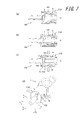
- FIGS. 2A and 2B are views showing a state where the medical connector according to the embodiment of the present invention is detached from another medical connector, in which FIG. 1A is a partial cross-sectional view taken along line AA in FIG. (D) is a partial cross-sectional view taken along the line BB, (c) is a partial cross-sectional view taken along the line CC of (d), and (d) is a perspective view.
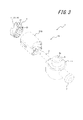
- FIGS. 2A and 2B are views showing the medical connector shown in FIG. 1, in which FIG. 1A is an exploded perspective view, FIG. 1B is a cross-sectional view taken along line DD in FIG. 1A, and FIG. It is sectional drawing. It is the disassembled perspective view seen from the other angle of the medical connector shown in FIG.
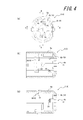
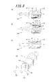
- FIG. 2 is a diagram showing a state at the start of connection of the medical connector shown in FIG. 1 and another medical connector, (a) is a partial cross-sectional view taken along line AA in (d), and (b) is (d) (C) is a partial cross-sectional view taken along the line CC of (d), and (d) is a perspective view.
- FIG. 2 is a diagram showing a state when connection is completed for the medical connector shown in FIG.
- FIG. 1 is a partial cross-sectional view along AA in (d), and (b) is (d) (C) is a partial cross-sectional view taken along the line CC of (d), and (d) is a perspective view.
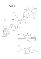
- FIG. 2 is a diagram showing a state at the start of disconnection of the medical connector shown in FIG. 1 and other medical connectors, (a) is a partial cross-sectional view along AA in (d), and (b) is ( (d) is a partial cross-sectional view taken along the line BB, (c) is a partial cross-sectional view taken along the line CC of (d), and (d) is a perspective view.
- FIG. 2 is a diagram showing the medical connector shown in FIG.
- FIG. (B) is a partial cross-sectional view taken along the line BB in (d)
- (c) is a partial cross-sectional view taken along the line CC in (d)
- (d) is a perspective view.
- FIGS. 2A and 2B are views showing a state when connection release is completed with respect to the medical connector shown in FIG. 1 and other medical connectors, in which FIG. 1A is a partial sectional view taken along line AA in FIG. (d) is a partial cross-sectional view taken along the line BB, (c) is a partial cross-sectional view taken along the line CC of (d), and (d) is a perspective view.
- FIG. 6 is a perspective view showing a cover member and a lock member in a state between a state at the start of connection shown in FIG. 5 and a state at the time of completion of connection shown in FIG. 6.
- FIG. 9 is a perspective view showing the cover member and the lock member in a state before the first lock state is released after the second lock state is released, as shown in FIG. 8. It is the perspective view seen from the other angle which shows the cover member and lock member in the state at the time of the connection start shown in FIG. FIG.
- FIG. 7 is a perspective view of the cover member and the lock member viewed from another angle in a state between the state at the start of connection shown in FIG. 5 and the state at the time of completion of connection shown in FIG. 6. It is the perspective view seen from the other angle which shows the cover member and lock member in the state at the time of the completion of a connection shown in FIG. It is the perspective view seen from the other angle which shows the cover member and lock member in the state before the 1st lock state cancellation
- FIG. 6 is a side view showing a cover member and a lock member in a state at the start of connection shown in FIG. 5.
- FIG. 6 is a side view showing the cover member and the lock member in a state between the state at the start of connection shown in FIG. 5 and the state at the time of completion of connection shown in FIG. 6. It is a side view which shows the cover member and lock member in the state at the time of the completion of a connection shown in FIG.
- FIG. 9 is a side view showing the cover member and the lock member in a state before the first lock state is released after the second lock state is released, as shown in FIG. 8.
- the tip side means the tip side of the male connector part 2 in the direction along the central axis O of the male connector part 2 of the medical connector 1 (for example, the left side in FIG. 1A).
- the base end side means the opposite side.
- the front is the distal end side of the medical connector 1
- the back is the proximal end of the medical connector 1
- the side is the left-right direction when viewed from the front to the back, and the top and bottom are when viewed from the front to the back. It means the vertical direction of.
- the medical connector 1 includes a connector main body 1 a including a male connector portion 2 and a cover portion 3 that surrounds the outer periphery of the male connector portion 2, and an inside of the cover portion 3. And a locking member 4 disposed on the surface.
- the male connector portion 2 is formed integrally with the housing 5, and the cover portion 3 is configured as a cover member 6 fixed to the housing 5.
- the housing 5 is formed with a female connector portion 7 and a mixed injection port portion 8. The opening portion of the mixed injection port portion 8 opens the opening portion when a male connector portion of various medical connectors is inserted to form a flow path, while the opening portion is not inserted when such a male connector portion is not inserted. Is provided with a valve body 8a.
- the housing 5 including the male connector portion 2, the female connector portion 7 and the mixed injection port portion 8, the cover member 6 fixed to the housing 5, and the mixed injection port portion 8 of the housing 5 are attached.
- the connector body 1a is configured by the valve body 8a.
- the housing 5, the cover member 6 and the lock member 4 can be made of, for example, a synthetic resin.
- the medical connector 1 is comprised as a T port connector provided with the female connector part 7 and the mixed injection port part 8 in addition to the male connector part 2 in this example, it is not restricted to such a structure. That is, the medical connector 1 may be configured as, for example, a three-way stopcock further added with a flow path switching structure, or may be configured as a male connector directly attached to an end portion of a tube connected to an infusion container or an indwelling needle. it can.
- the cover member 6 includes an outer peripheral wall portion 6a that can surround the lock member 4, and a partition wall portion 6b that partially closes the proximal end side of the outer peripheral wall portion 6a.
- the partition wall portion 6b is provided with a through hole 6c, and the partition wall portion 6b can be fitted to the proximal end portion of the male connector portion 2 while allowing the male connector portion 2 to pass through the through hole 6c.
- the cover member 6 is configured to be rotationally symmetric about the central axis O of the male connector 2.
- a distal end side stopper portion 9 composed of a plurality of (four in this example) projections 6d arranged at intervals in the circumferential direction is formed.
- the base end side stopper portion 10 is formed by the partition wall portion 6b. The distal end side stopper portion 9 and the proximal end side stopper portion 10 limit the movement range of the lock member 4 to the distal end side and the proximal end side when the lock member 4 is disposed in the cover member 6.
- the lock member 4 can move with respect to the cover member 6 only in a predetermined range in the direction along the axis O of the male connector portion 2. Further, on the inner peripheral surface of the cover member 6, there are a first inner diameter portion 6e having a first inner diameter and a second inner diameter portion 6f having a second inner diameter that is smaller than the first inner diameter portion 6e. Is provided.
- the lock member 4 is configured to be rotationally symmetric about the central axis O of the male connector 2 in the present embodiment.
- the lock member 4 includes a first lock part 11. As shown in FIG. 6B, the first lock portion 11 can be engaged with the female connector portion 101 of another medical connector 100 to place the female connector portion 101 in the first locked state. is there. That is, the first locked state means a state where the first lock portion 11 and the female connector portion 101 are engaged.
- the first lock portion 11 includes a plurality (two in this example) of two (two in this example) provided on the distal end side of the plurality of (two in this example) elastic pieces 12.
- the first engaging portion 13 is formed. More specifically, the plurality of first engagement portions 13 are provided as a plurality (two in this example) of first engagement protrusions 14 provided on the distal ends of the plurality of elastic pieces 12 and projecting radially inward. Is formed.
- the plurality of first engagement protrusions 14 are a plurality of (two in this example) first recesses provided on the outer peripheral surface 102 of the female connector portion 101 of the other medical connector 100 shown in FIG. It can be engaged with one engaging recess 103 (first locking portion engaging recess).
- the medical connector 1 includes a second lock portion 15 and a second lock release operation portion 16 as shown in FIG.
- the second lock portion 15 is connected to the female connector portion 101, and the female connector portion 101 is a male connector portion. 2 can be set to the second locked state in which it cannot move in the disengagement direction (see FIG. 6C).
- the second unlocking operation unit 16 is an operation unit for canceling the second locked state.
- the second lock portion 15 is configured to bring the female connector portion 101 into the second locked state by engaging the female connector portion 101 of the other medical connector 100 with the cover member 6. Yes. More specifically, the second lock portion 15 includes a second engagement protrusion portion 15 a provided on the cover member 6 and protruding radially inward.
- the second engagement protrusion portion 15 a is an outer periphery of the female connector portion 101. It can be engaged with a second engaging recess 104 (second locking portion engaging recess) provided in the surface 102.
- the second unlocking operation portion 16 is an operation portion for the swing lever 17 that is provided integrally with the outer peripheral wall portion 6 a of the cover member 6 while having the second engagement projection portion 15 a.
- the 2nd lock part 15 and the 2nd lock release operation part 16 are each provided in two places which oppose on both sides of the axis line O of the male connector part 2. As shown in FIG.
- the medical connector 1 When the male connector portion 2 is inserted into the female connector portion 101 of the other medical connector 100, the medical connector 1 causes the lock member 4 to be female as shown in FIGS. 5 (b) and 5 (c). A plurality of elastic pieces 12 of the lock member 4 are moved to the base end side of the male connector portion 2 while being rotated in the first rotation direction by being pushed by the connector portion 101 (FIG. 5A). 6 (b) and 6 (c), the first lock portion 11 is engaged with the female connector portion 101, and the female connector portion 101 is The first lock state and the second lock state are set (that is, the connection between the male connector portion 2 and the female connector portion 101 is completed).
- the medical connector 1 is configured so that the connection between the male connector portion 2 and the female connector portion 101 can be released in the following manner. That is, as shown in FIG. 7, the second locked state is released by the operation of the second unlocking operation part 16, and the female connector part 101 is moved away from the male connector part 2 as shown in FIG. 8.
- the lock member 4 moves in the detaching direction together with the female connector portion 101 while maintaining the first locked state.
- the lock member 4 also rotates together with the female connector 101.
- the plurality of elastic pieces 12 of the lock member 4 are restored from the elastic deformation, and the first locked state is canceled along with the restoration (connection release complete).
- the medical connector 1 in order to release the connection with the other medical connector 100, the medical connector 1 operates the second unlocking operation unit 16, the pulling operation of the female connector unit 101, and the female connector unit 101. It is necessary to go through three operations called a rotation operation. In addition, these three operations have different directions of force required for the operations. Therefore, the medical connector 1 can reliably prevent the occurrence of unintentional detachment from other medical connectors 100.
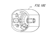
- FIGS. 10A to 12D are perspective views showing the cover member 6 and the lock member 4.
- FIG. 10A shows the state at the start of connection shown in FIG. 5, and
- FIG. 10B shows the state at the start of connection shown in FIG. 10C shows a state between the connection state shown in FIG. 6 and the connection completion state shown in FIG. 6,
- FIG. 10C shows the connection completion state shown in FIG. 6,
- FIG. 10D shows the second state shown in FIG. A state after the lock state is released and before the first lock state is released is shown.
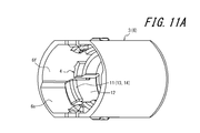
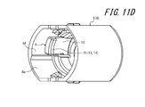
- FIGS. 11A to 11D are perspective views showing the cover member 6 and the lock member 4 from other angles, and FIGS. 11A to 11D show the same states as FIGS. 10A to 10D, respectively.
- 12A to 12D are side views showing the cover member 6 and the lock member 4, and FIGS. 12A to 12D show the same states as FIGS. 10A to 10D, respectively.
- a first contact surface 18 is provided on the inner peripheral surface of the cover member 6 as shown in FIGS. 12A to 12C in particular.
- a second contact surface 19 is provided on the outer peripheral surface.
- at least one of the first contact surface 18 and the second contact surface 19 is formed along a chord-shaped track. More specifically, in the present embodiment, both the first contact surface 18 and the second contact surface 19 are formed along a chord-shaped track. Then, when the lock member 4 is moved to the base end side (back side) with respect to the cover member 6, the second contact surface 19 is pressed against the first contact surface 18, whereby the lock member 4. Is rotated in the first rotation direction (see FIGS. 12A to 12C and FIGS. 10A to 10C).
- the lock member 4 in order to cause elastic deformation of the plurality of elastic pieces 12 of the lock member 4, the lock member 4 is first rotated with respect to the cover member 6 as shown in FIGS. 11A to 11C in particular.
- Each of the plurality of elastic pieces 12 is elastically deformed radially inward with the movement from the first inner diameter portion 6e to the second inner diameter portion 6f, and the plurality of first elastic pieces 12 are
- Each of the first engaging portions 13 engages with the female connector portion 101 (see FIG. 6B and FIG. 11C).
- each of the plurality of elastic pieces 12 moves from the second inner diameter portion 6f to the first inner diameter portion 6e, and is restored to the outside in the radial direction along with the movement. 13 is disengaged from the female connector portion 101 (see FIG. 9A).
- the rotation of the lock member 4 in the second rotation direction is performed by rotating the female connector portion 101 in the second rotation direction, so that the plurality of first engagement recesses 103 of the female connector portion 101 shown in FIG.
- the plurality of first engaging protrusions 14 are pushed by the end edge 103a.
- the cover member 6 is provided with a plurality of (two in this example) elastic pieces extending from the partition wall portion 6b to the front end side.
- a plurality (two in this example) of third engaging protrusions 20 that can be engaged with the lock member 4 are provided.
- the plurality of third engagement protrusions 20 are a plurality (two in this example) of the lock members 4.
- the engagement with the opening 21 creates a feeling of moderation (see FIG. 6 (b)).
- the engagement between the engagement protrusion 20 and the plurality of openings 21 of the lock member 4 is released to create a sense of moderation (see FIG. 8B).
- a plurality of (two in this example) fourth engagement protrusions 22 are provided on the inner peripheral surface of the outer peripheral wall 6 a of the cover member 6. Yes. Further, the lock member 4 is provided with a plurality (two in this example) of fifth engagement protrusions 23 that can be engaged with the plurality of fourth engagement protrusions 22 (see FIG. 10D).
- the lock member 4 is rotated in the second rotational direction with respect to the cover member 6 after the lock member 4 reaches the end of the movable range in the cover member 6 (that is, FIG. 10D).
- the plurality of fifth engagement protrusions 23 get over the plurality of fourth engagement protrusions 22 to generate a sense of moderation.
- the opening of the female connector 101 of another medical connector 100 is opened to flow when the male connector 2 of the medical connector 1 is inserted.
- a valve body 105 is provided to close the opening when the male connector portion 2 is not inserted.
- a biasing force is applied to the top surface portion 105a of the valve body 105 from the flow path side of the female connector portion 101 toward the top surface portion side.
- a specific structure for generating such an urging force is not shown in the drawing, but as such a structure, for example, a coiled spring separate from the valve body 105 may be arranged in the flow path.
- a bellows-like elastic portion may be provided integrally with the top surface portion 105a of the valve body 105.
- valve body 105 to open the opening of the female connector part 101 to form the flow path when the male connector part 2 of the medical connector 1 is inserted is omitted.
- a groove for partitioning a part of the flow path formed when the opening of the female connector part 101 is opened can be appropriately provided in the housing of the valve body 105 or the female connector part 101.
- the medical connector 1 is disposed in the connector main body 1a including the male connector portion 2 and the cover portion 3 surrounding the outer periphery of the male connector portion 2, and the cover portion 3.
- a lock member 4 that is movable only within a predetermined range in a direction along the axis O of the male connector portion 2 with respect to the cover portion 3 and includes the first lock portion 11, a second lock portion 15, and a second lock And a release operation unit 16.
- the 1st lock part 11 can engage with the female connector part 101 of the other medical connector 100, and can make the female connector part 101 into a 1st locked state.
- the 2nd lock part 15 can make the female connector part 2 into a 2nd locked state which cannot move the female connector part 2 with respect to the male connector part 2 in a 1st locked state.
- the second lock release operation unit 16 is an operation unit for canceling the second lock state.
- the 1st lock part 11 will engage with the female connector part 101, and the female connector part 101 will be in a 1st locked state, and 2nd. It is configured to be locked.
- the first locked state is configured to be eliminated when the female connector unit 101 is moved in the disengagement direction together with the female connector unit 101 while the first locked state is maintained and the female connector unit 101 is rotated with respect to the male connector unit 2. Yes.
- the medical connector 1 when the male connector portion 2 is inserted into the female connector portion 101, the first lock portion 11 is engaged with the female connector portion 101, and the female connector portion 101 is the first.
- the lock state is entered and the second lock state is entered. Therefore, according to this embodiment, the connectors 1 and 100 can be connected to each other only by inserting the male connector portion 2 into the female connector portion 101 of the other medical connector 100. Further, in this connected state, since the first lock portion 11 is located in the cover portion 3, it is possible to prevent unintentional disconnection of the connectors 1, 100 due to external force acting on the first lock portion 11. .
- a 2nd lock state is canceled by operation of the 2nd lock release operation part 16 from the connection state of this connectors 1 and 100, and the female connector part 101 is made.
- the lock member 4 moves in the disengagement direction together with the female connector portion 101 while maintaining the first locked state, and the female connector portion 101 is changed to the male connector portion 2. If it rotates with respect to it, a 1st locked state can be canceled.
- the operation of the second unlocking operation unit 16 in order to release the connection between the connectors 1 and 100, the operation of the second unlocking operation unit 16, the pulling operation of the female connector unit 101, and the rotating operation of the female connector unit 101 are referred to. It is necessary to go through three operations.
- the medical connector 1 it is possible to more reliably prevent the occurrence of unintentional disconnection while ensuring the ease of connection operation with respect to the other medical connector 100.
- the lock member 4 when the male connector portion 2 is inserted into the female connector portion 101, the lock member 4 is pushed by the female connector portion 101 and moves to the proximal end side of the male connector portion 2.
- the lock member 4 is elastically deformed with the movement, and when the first lock portion 11 is engaged with the female connector portion 101 with the elastic deformation, the female connector portion 101 is
- the male connector portion 2 is rotated, the lock member 4 is rotated together with the female connector portion 101, and the lock member 4 is restored from the elastic deformation along with the rotation, and the first locked state is eliminated along with the restoration. Is configured to do.
- the female connector 101 can be brought into the first locked state and the first locked state can be eliminated with a simple structure.
- the lock member 4 when the male connector portion 2 is inserted into the female connector portion 101, the lock member 4 is pushed by the female connector portion 101 and is first on the proximal end side of the male connector portion 2.
- the direction in which the female connector portion 101 is rotated with respect to the male connector portion 2 when moving with the rotation in the rotational direction and releasing the first locked state is opposite to the first rotational direction. It is comprised so that it may become 2 rotation directions.
- the female connector 101 can be brought into the first locked state and the first locked state can be eliminated with a simple structure.
- the first contact surface 18 is provided on the inner peripheral surface of the cover portion 3, and the second contact surface 19 is provided on the outer peripheral surface of the lock member 4. And at least one of the first abutment surface 18 and the second abutment surface 19 is formed along a chordal orbit, and the second abutment surface 19 is the first abutment surface 19.
- the lock member 4 is configured to be rotated in the first rotational direction with respect to the male connector portion 2.
- the lock member 4 can be rotated with a simple structure.
- the first lock portion 11 is formed as a plurality of first engagement portions 13 provided on the distal end side of the plurality of elastic pieces 12, and the cover portion 3
- the inner peripheral surface is provided with a first inner diameter portion 6e having a first inner diameter, and a second inner diameter portion 6f having a second inner diameter that is smaller than the first inner diameter portion 6e.
- the lock member 4 can be elastically deformed and the first lock portion 11 can be engaged with the female connector portion 101 with a simple structure.
- the medical connector 1 includes a plurality of first engaging portions 13 provided on the distal end side of the plurality of elastic pieces 12 and protruding inward in the radial direction.
- the plurality of first engagement protrusions 14 are formed so as to be engageable with a plurality of first engagement recesses 103 recessed in the outer peripheral surface 102 of the female connector portion 101.
- the plurality of first engaging portions 13 can be reliably engaged with the female connector portion 101 with a simple structure.
- the medical connector 1 is configured such that the second lock portion 15 causes the female connector portion 101 to be in the second locked state by engaging the female connector portion 101 with the cover portion 3. ing.
- the second lock portion 15 can be realized with a simple structure.
- the second lock portion 15 includes a second engagement projection portion 15a that is provided on the cover portion 3 and protrudes inward in the radial direction.
- the second engagement recess 104 can be engaged with the second engagement recess 104 provided in the outer peripheral surface 102 of the female connector portion 101, and the second unlocking operation portion 16 has a second engagement protrusion 15 a and is attached to the cover portion 3. It is configured to be an operating portion of the swing lever 17 provided integrally.
- the second unlocking operation unit 16 can be realized with a simple structure.
- the second lock portion 15 has been described as being configured to bring the female connector portion 101 into the second locked state by engaging the female connector portion 101 with the cover portion 3.
- the configuration is not necessarily limited to such a configuration.
- the female connector unit 101 can be configured to be in the second locked state by engaging the lock member 4 with the cover unit 3.
Landscapes
- Health & Medical Sciences (AREA)
- Heart & Thoracic Surgery (AREA)
- Pulmonology (AREA)
- Engineering & Computer Science (AREA)
- Anesthesiology (AREA)
- Biomedical Technology (AREA)
- Hematology (AREA)
- Life Sciences & Earth Sciences (AREA)
- Animal Behavior & Ethology (AREA)
- General Health & Medical Sciences (AREA)
- Public Health (AREA)
- Veterinary Medicine (AREA)
- Infusion, Injection, And Reservoir Apparatuses (AREA)
Abstract
本発明の医療用コネクタは、オスコネクタ部をメスコネクタ部に挿入すると、第1ロック部がメスコネクタ部と係合し、第1ロック状態になると共に第2ロック状態となり、第2ロック解除操作部の操作にて第2ロック状態を解消させ、メスコネクタ部をオスコネクタ部に対して離脱方向に移動させると、ロック部材が、第1ロック状態を維持したままでメスコネクタ部と共に前記離脱方向に移動し、メスコネクタ部をオスコネクタ部に対して回転させると、第1ロック状態が解消することを特徴とするものである。
Description
本発明は、医療用コネクタに関し、特に、他の医療用コネクタに対する接続操作の容易性を確保しつつ、意図しない離脱の発生をより確実に防止しようとするものである。
従来、患者に薬液を注入するための輸液セットや、その他の医療用器具などにおいて、流路を接続するために医療用コネクタが用いられている。このような医療用コネクタの接続は、通常、一方のコネクタに設けられたオスコネクタ部を、他方のコネクタに設けられたメスコネクタ部に挿入することでなされる。また、コネクタの意図しない離脱の発生を防止するために、コネクタ間に係合部を設けることも一般的である。例えば、ルアーロック方式のコネクタでは、係合部としてねじを用いているが、その接続に際しては、オスコネクタ部をメスコネクタ部に挿入し、ねじ止めするという2段階の接続操作が必要となり、接続操作が煩雑であった。また、外力の作用によりねじに緩みが生じると、コネクタの意図しない離脱が発生するおそれもあった。
このような問題を解決するものとして、例えば、特許文献1~2に記載されるように、係合部として複数の爪を用いるものが知られている。特許文献1~2に記載の医療用コネクタは、オスコネクタ部と複数の爪とを備えており、オスコネクタ部を他の医療用コネクタのメスコネクタ部に挿入すると、複数の爪が、他の医療用コネクタに形成された段部を弾性変形しつつ乗り越え、復元することで、該段部からの引き抜けを防止するようになっている。このような構成によれば、オスコネクタ部をメスコネクタ部に挿入するだけでコネクタ同士を接続できるため、接続操作を容易化することができる。また、係合部としてねじを用いていため、ねじの緩みに起因するコネクタの意図しない離脱が発生することもない。
しかしながら、特許文献1~2に記載されるような構成の医療用コネクタでは、他の医療用コネクタとの接続状態で爪に外力が作用した場合に、爪が弾性変形しつつ段部を引き抜け方向に乗り越え、コネクタの意図しない離脱を生じてしまう余地があった。
本発明は、前記の現状に鑑み開発されたもので、他の医療用コネクタに対する接続操作の容易性を確保しつつ、意図しない離脱の発生をより確実に防止できる医療用コネクタを提供することを目的とする。
本発明の医療用コネクタは、オスコネクタ部と該オスコネクタ部の外周を取り囲むカバー部とを備えるコネクタ本体と、前記カバー部内に配置され、前記カバー部に対して前記オスコネクタ部の軸線に沿う方向に所定の範囲内のみにおいて移動可能であると共に第1ロック部を備えるロック部材と、第2ロック部と、第2ロック解除操作部とを備え、前記第1ロック部は、他の医療用コネクタのメスコネクタ部と係合し、前記メスコネクタ部を第1ロック状態にすることが可能であり、前記第2ロック部は、前記第1ロック状態において、前記メスコネクタ部を、該メスコネクタ部が前記オスコネクタ部に対して離脱方向に移動できない第2ロック状態にすることが可能であり、前記第2ロック解除操作部は、前記第2ロック状態を解消させるための操作部であり、前記オスコネクタ部を前記メスコネクタ部に挿入すると、前記第1ロック部が前記メスコネクタ部と係合し、前記メスコネクタ部が前記第1ロック状態になると共に前記第2ロック状態となり、前記第2ロック解除操作部の操作にて前記第2ロック状態を解消させ、前記メスコネクタ部を前記オスコネクタ部に対して離脱方向に移動させると、前記ロック部材が、前記第1ロック状態を維持したままで前記メスコネクタ部と共に前記離脱方向に移動し、前記メスコネクタ部を前記オスコネクタ部に対して回転させると、前記第1ロック状態が解消することを特徴とする。
ここで、本発明の医療用コネクタは、前記オスコネクタ部を前記メスコネクタ部に挿入すると、前記ロック部材は、前記メスコネクタ部に押されて前記オスコネクタ部の基端側に移動し、該移動に伴って前記ロック部材が弾性変形し、該弾性変形に伴って前記第1ロック部が前記メスコネクタ部と係合し、前記第1ロック状態を解消する際に、前記メスコネクタ部を前記オスコネクタ部に対して回転させると、前記ロック部材が前記メスコネクタ部と共に回転し、該回転に伴って前記ロック部材が前記弾性変形から復元し、該復元に伴って前記第1ロック状態が解消することが好ましい。
また、本発明の医療用コネクタは、前記オスコネクタ部を前記メスコネクタ部に挿入すると、前記ロック部材は、前記メスコネクタ部に押されて前記オスコネクタ部の基端側に第1の回転方向への回転を伴いつつ移動し、前記第1ロック状態を解消する際に、前記メスコネクタ部を前記オスコネクタ部に対して回転させる方向は、前記第1の回転方向と反対方向である第2の回転方向であることが好ましい。
また、本発明の医療用コネクタは、前記カバー部の内周面には第1の当接面が設けられており、前記ロック部材の外周面には第2の当接面が設けられており、前記第1の当接面と前記第2の当接面のうちの少なくとも一方が弦巻状の軌道に沿って形成されており、前記第2の当接面が前記第1の当接面に押し当てられることで、前記ロック部材が前記オスコネクタ部に対して前記第1の回転方向に回転させられることが好ましい。
また、本発明の医療用コネクタは、前記第1ロック部が、複数の弾性片の先端側に設けられた複数の係合部として形成されており、前記カバー部の内周面には、第1の内径を有する第1内径部と、該第1内径部よりも縮径された第2の内径を有する第2内径部とが設けられており、前記ロック部材が前記メスコネクタ部に押されて前記オスコネクタ部の基端側に移動すると、前記複数の弾性片のそれぞれが前記第1内径部から前記第2内径部への移動に伴って径方向内側に弾性変形し、該弾性変形に伴って、複数の係合部として形成された前記第1ロック部のそれぞれが前記メスコネクタ部と係合することが好ましい。
また、本発明の医療用コネクタは、前記第1ロック部が、前記複数の弾性片の先端側に設けられ径方向内側に突出する複数の係合突起部として形成されており、複数の係合突起部として形成された前記第1ロック部は、前記メスコネクタ部の外周面に凹設された複数の第1ロック部用係合凹部と係合可能であることが好ましい。
また、本発明の医療用コネクタは、前記第2ロック部が、前記メスコネクタ部を前記カバー部に係合させることで、前記メスコネクタ部を前記第2ロック状態にすることが好ましい。
さらに、本発明の医療用コネクタは、前記第2ロック部が、前記カバー部に設けられ径方向内側に突出する係合突起部からなり、係合突起部からなる前記第2ロック部は、前記メスコネクタ部の外周面に凹設された第2ロック部用係合凹部と係合可能であり、前記第2ロック解除操作部は、係合突起部からなる前記第2ロック部を有すると共に前記カバー部に一体に設けられた揺動レバーの操作部であることが好ましい。
本発明によれば、オスコネクタ部をメスコネクタ部に挿入すると、第1ロック部がメスコネクタ部と係合し、メスコネクタ部が第1ロック状態になると共に第2ロック状態となる。したがって、本発明によれば、オスコネクタ部を他の医療用コネクタのメスコネクタ部に挿入するだけでコネクタ同士を接続することができる。また、この接続状態において、第1ロック部はカバー部内に位置しているため、第1ロック部に外力が作用してコネクタの意図しない離脱を生じることが防止される。
また、本発明によれば、このコネクタ同士の接続状態から、第2ロック解除操作部の操作にて第2ロック状態を解消させ、メスコネクタ部をオスコネクタ部に対して離脱方向に移動させると、ロック部材が、第1ロック状態を維持したままでメスコネクタ部と共に前記離脱方向に移動し、メスコネクタ部を前記オスコネクタ部に対して回転させると、第1ロック状態を解消させることができる。したがって、本発明によれば、コネクタ同士の接続を解除するためには、第2ロック解除操作部の操作、メスコネクタ部の引っ張り操作、及びメスコネクタ部の回転操作という3つの操作を経る必要がある。
したがって、本発明によれば、他の医療用コネクタに対する接続操作の容易性を確保しつつ、意図しない離脱の発生をより確実に防止できる医療用コネクタを提供することができる。
以下、図1~図12Dを参照して、本発明の一実施形態に係る医療用コネクタ1について詳細に例示説明する。
なお、本明細書において、先端側とは、医療用コネクタ1のオスコネクタ部2の中心軸線Oに沿う方向におけるオスコネクタ部2の先端側(例えば、図1(a)における左側)を意味し、基端側とはその反対側を意味するものとする。また、正面は医療用コネクタ1の先端側、背面は医療用コネクタ1の基端側、側面は正面から背面に向かって見たときの左右方向、上下面は正面から背面に向かって見たときの上下方向を意味するものとする。
なお、本明細書において、先端側とは、医療用コネクタ1のオスコネクタ部2の中心軸線Oに沿う方向におけるオスコネクタ部2の先端側(例えば、図1(a)における左側)を意味し、基端側とはその反対側を意味するものとする。また、正面は医療用コネクタ1の先端側、背面は医療用コネクタ1の基端側、側面は正面から背面に向かって見たときの左右方向、上下面は正面から背面に向かって見たときの上下方向を意味するものとする。
図1~図3に示すように、本実施形態に係る医療用コネクタ1は、オスコネクタ部2と該オスコネクタ部2の外周を取り囲むカバー部3とを備えるコネクタ本体1aと、カバー部3内に配置されたロック部材4とを備えている。本例では、オスコネクタ部2は、ハウジング5に一体に形成されており、カバー部3は、ハウジング5に固定されたカバー部材6として構成されている。また、ハウジング5には、メスコネクタ部7と混注ポート部8とが形成されている。混注ポート部8の開口部には、種々の医療用コネクタのオスコネクタ部の挿入時に該開口部を開放して流路を形成する一方で、そのようなオスコネクタ部の非挿入時には該開口部を閉鎖する弁体8aが設けられている。
このように、本例では、オスコネクタ部2、メスコネクタ部7及び混注ポート部8を含むハウジング5と、該ハウジング5に固定されたカバー部材6と、ハウジング5の混注ポート部8に取り付けられた弁体8aとによって、コネクタ本体1aが構成されている。ハウジング5、カバー部材6及びロック部材4は、例えば合成樹脂製とすることができる。
なお、医療用コネクタ1は、本例ではオスコネクタ部2に加えてメスコネクタ部7及び混注ポート部8も備えるTポートコネクタとして構成されているが、このような構成に限られるものではない。すなわち、医療用コネクタ1は、例えば、流路切替え構造をさらに加えた三方活栓として構成したり、輸液容器或いは留置針に繋がるチューブの端部に直接取付けられたオスコネクタとして構成したりすることができる。
図4に示すように、カバー部材6は、ロック部材4を取り囲むことが可能な外周壁部6aと、外周壁部6aの基端側を部分的に閉塞する隔壁部6bとを備えている。隔壁部6bには貫通孔6cが設けられ、該貫通孔6cにオスコネクタ部2を貫通させつつ、隔壁部6bをオスコネクタ部2の基端部に嵌合できるようになっている。
カバー部材6は、本実施形態では、オスコネクタ2の中心軸線Oを中心とする回転対称をなすように構成されている。外周壁部6aの内周面には、周方向に間隔を空けて配置された複数(本例では4つ)の突起6dからなる先端側ストッパ部9が形成されている。また、隔壁部6bで基端側ストッパ部10が形成される。これらの先端側ストッパ部9及び基端側ストッパ部10により、ロック部材4がカバー部材6内に配置されたとき、ロック部材4の先端側及び基端側への移動範囲が制限される。その結果、ロック部材4は、カバー部材6に対してオスコネクタ部2の軸線Oに沿う方向に所定の範囲内のみにおいて移動可能となる。また、カバー部材6の内周面には、第1の内径を有する第1内径部6eと、該第1内径部6eよりも縮径された第2の内径を有する第2内径部6fとが設けられている。
ロック部材4は、図2及び図3に示すように、本実施形態では、オスコネクタ2の中心軸線Oを中心とする回転対称をなすように構成されている。また、ロック部材4は、第1ロック部11を備えている。第1ロック部11は、後掲図6(b)に示すように、他の医療用コネクタ100のメスコネクタ部101と係合し、メスコネクタ部101を第1ロック状態にすることが可能である。すなわち、第1ロック状態とは、第1ロック部11とメスコネクタ部101とが係合した状態を意味する。
本実施形態では、第1ロック部11は、図2及び図3に示すように、複数(本例では2つ)の弾性片12の先端側に設けられた複数(本例では2つ)の第1係合部13として形成されている。より具体的には、複数の第1係合部13は、複数の弾性片12の先端側に設けられ径方向内側に突出する複数(本例では2つ)の第1係合突起部14として形成されている。複数の第1係合突起部14は、特に図1(d)に示す、他の医療用コネクタ100のメスコネクタ部101の外周面102に凹設された複数(本例では2つ)の第1係合凹部103(第1ロック部用係合凹部)と係合可能である。
また、医療用コネクタ1は、後掲図6(c)に示すように、第2ロック部15と第2ロック解除操作部16とを備えている。第2ロック部15は、第1ロック部11と他の医療用コネクタ100のメスコネクタ部101とが係合した第1ロック状態において、メスコネクタ部101を、該メスコネクタ部101がオスコネクタ部2に対して離脱方向に移動できない第2ロック状態にする(後掲図6(c)参照)ことが可能である。第2ロック解除操作部16は、第2ロック状態を解消させるための操作部である。
第2ロック部15は、本実施形態では、他の医療用コネクタ100のメスコネクタ部101をカバー部材6に係合させることで、メスコネクタ部101を第2ロック状態にするように構成されている。より具体的には、第2ロック部15は、カバー部材6に設けられ径方向内側に突出する第2係合突起部15aからなり、第2係合突起部15aは、メスコネクタ部101の外周面102に凹設された第2係合凹部104(第2ロック部用係合凹部)と係合可能である。そして、第2ロック解除操作部16は、第2係合突起部15aを有すると共にカバー部材6の外周壁部6aに一体に設けられた揺動レバー17の操作部となっている。本実施形態では、第2ロック部15と第2ロック解除操作部16は、それぞれ、オスコネクタ部2の軸線Oを挟んで対向する2箇所に設けられている。
そして、医療用コネクタ1は、オスコネクタ部2を他の医療用コネクタ100のメスコネクタ部101に挿入すると、図5(b)及び図5(c)に示すように、ロック部材4が、メスコネクタ部101に押されてオスコネクタ部2の基端側に第1の回転方向への回転を伴いつつ移動し、該回転に伴ってロック部材4の複数の弾性片12(図5(a)参照)が弾性変形し、該弾性変形に伴って、図6(b)及び図6(c)に示すように、第1ロック部11がメスコネクタ部101と係合し、メスコネクタ部101が第1ロック状態になると共に第2ロック状態となる(すなわち、オスコネクタ部2とメスコネクタ部101との接続完了状態となる)ように構成されている。
また、医療用コネクタ1は、オスコネクタ部2とメスコネクタ部101との接続を以下の要領で解除できるように構成されている。すなわち、図7に示すように、第2ロック解除操作部16の操作にて第2ロック状態を解消させ、図8に示すように、メスコネクタ部101をオスコネクタ部2に対して離脱方向に移動させると、ロック部材4が、第1ロック状態を維持したままでメスコネクタ部101と共に前記離脱方向に移動する。そして、図9に示すように、メスコネクタ部101を第1の回転方向と反対方向である第2の回転方向に回転させると、ロック部材4もメスコネクタ101と共に回転し、該回転に伴ってロック部材4の複数の弾性片12が前記弾性変形から復元し、該復元に伴って第1ロック状態が解消する(接続解除完了)。
このように、医療用コネクタ1は、他の医療用コネクタ100との接続を解除するためには、第2ロック解除操作部16の操作、メスコネクタ部101の引っ張り操作、及びメスコネクタ部101の回転操作という3つの操作を経る必要がある。また、この3つの操作はそれぞれ操作に必要な力の向きが異なる。したがって、医療用コネクタ1は、他の医療用コネクタ100からの意図しない離脱の発生を確実に防止できるようになっている。
このようなロック部材4の移動、回転、弾性変形及び復元を生じさせるための、本実施形態における具体的構造について、図10A~図12Dを用いて以下に詳細に説明する。図10A~図10Dは、カバー部材6とロック部材4を示す斜視図であり、図10Aは、図5に示した接続開始時の状態を示し、図10Bは、図5に示した接続開始時の状態と図6に示した接続完了時の状態との間の状態を示し、図10Cは、図6に示した接続完了時の状態を示し、図10Dは、図8に示した、第2ロック状態解消後、第1ロック状態解消前の状態を示している。
また、図11A~図11Dは、カバー部材6とロック部材4を示す他の角度から見た斜視図であり、図11A~図11Dはそれぞれ図10A~図10Dと同じ状態を示している。さらに、図12A~図12Dは、カバー部材6とロック部材4を示す側面図であり、図12A~図12Dはそれぞれ図10A~図10Dと同じ状態を示している。
本実施形態では、ロック部材4の回転を生じさせるために、特に図12A~図12Cに示すように、カバー部材6の内周面に第1の当接面18が設けられ、ロック部材4の外周面に第2の当接面19が設けられている。そして、第1の当接面18と第2の当接面19のうちの少なくとも一方が弦巻状の軌道に沿って形成されている。本実施形態においては、より具体的には、第1の当接面18と第2の当接面19の双方が、弦巻状の軌道に沿って形成されている。そして、ロック部材4がカバー部材6に対して基端側(背面側)に移動させられると、第2の当接面19が第1の当接面18に押し当てられることで、ロック部材4が第1の回転方向に回転させられる(図12A~図12C、図10A~図10C参照)ようになっている。
また、本実施形態では、ロック部材4の複数の弾性片12の弾性変形を生じさせるために、特に図11A~図11Cに示すように、ロック部材4がカバー部材6に対して第1の回転方向に回転させられると、複数の弾性片12のそれぞれが第1内径部6eから第2内径部6fへの移動に伴って径方向内側に弾性変形し、該弾性変形に伴って、複数の第1係合部13のそれぞれがメスコネクタ部101と係合する(図6(b)、図11C参照)ようになっている。
そして、本実施形態では、この状態から、ロック部材4がカバー部材6に対して先端側(正面側)に移動させられると、図10D、図11D、図12Dに示すように、ロック部材4は回転を伴うことなく、且つ、複数の弾性片12のそれぞれが第2内径部6fに位置したままで移動するようになっている。このため、ロック部材4がカバー部材6に対して先端側(正面側)に移動させられる際は、複数の弾性片12の弾性変形は維持され、複数の第1係合部13とメスコネクタ部101との係合状態、すなわち、第1ロック状態は維持される(図8(b)参照)。
また、本実施形態では、この状態(図11D、図12D参照)から、ロック部材4がカバー部材6に対して第2の回転方向に回転させられると、特に図11A及び図12Aに示したように、複数の弾性片12のそれぞれが第2内径部6fから第1内径部6eへ移動し、該移動に伴って径方向外側に復元し、該復元に伴って、複数の第1係合部13のそれぞれとメスコネクタ部101との係合が解除される(図9(a)参照)ようになっている。なお、ロック部材4の第2の回転方向への回転は、メスコネクタ部101を第2の回転方向に回転させることにより、図1に示したメスコネクタ部101の複数の第1係合凹部103の端縁103aに、複数の第1係合突起部14(図8(b)参照)が押されることで生じるようになっている。
なお、カバー部材6には、特に図4に示したように、隔壁部6bから先端側へ延びる複数(本例では2つ)の弾性片が設けられており、該弾性片の先端側にはロック部材4と係合可能な複数(本例では2つ)の第3係合突起部20が設けられている。そして、ロック部材4がカバー部材6内の移動可能範囲の基端側端部に達したときに、この複数の第3係合突起部20がロック部材4の複数(本例では2つ)の開口部21(図3参照)と係合して節度感を生じさせ(図6(b)参照)、また、ロック部材4が該基端側端部から脱するときに、この複数の第3係合突起部20とロック部材4の複数の開口部21との係合が解除されて節度感を生じさせる(図8(b)参照)ようになっている。
また、カバー部材6の外周壁部6aの内周面には、図4、図10A及び図10Dに示すように、複数(本例では2つ)の第4係合突起部22が設けられている。また、ロック部材4には、この複数の第4係合突起部22と係合可能な複数(本例では2つ)の第5係合突起部23が設けられている(図10D参照)。そして、ロック部材4がカバー部材6内の移動可能範囲の先端側端部に達した後、ロック部材4がカバー部材6に対して第2の回転方向に回転させられたとき(すなわち、図10Dの状態から図10Aの状態になるとき)に、複数の第5係合突起部23が複数の第4係合突起部22を乗り越えることで節度感を生じさせるようになっている。
なお、特に図1(a)に示すように、他の医療用コネクタ100のメスコネクタ部101の開口部には、医療用コネクタ1のオスコネクタ部2の挿入時に該開口部を開放して流路を形成する一方で、オスコネクタ部2の非挿入時には該開口部を閉鎖する弁体105が設けられている。本例では、弁体105の天面部105aには、メスコネクタ部101の流路側から天面部側に向けて付勢力が付与されている。このような付勢力を生じさせるための具体的な構造は図示を省略しているが、そのような構造としては、例えば、弁体105と別体の弦巻ばねを流路内に配置してもよいし、弁体105の天面部105aと一体に蛇腹状の弾性部を設けてもよい。
また、医療用コネクタ1のオスコネクタ部2の挿入時に弁体105がメスコネクタ部101の開口部を開放して流路を形成するための具体的な構造についても図示を省略しているが、そのような構造としては、例えば、弁体105やメスコネクタ部101のハウジングに、メスコネクタ部101の開口部の開放時に形成される流路の一部を区画する溝を適宜設けることができる。
以上説明したように、本実施形態に係る医療用コネクタ1は、オスコネクタ部2と該オスコネクタ部2の外周を取り囲むカバー部3とを備えるコネクタ本体1aと、カバー部3内に配置され、カバー部3に対してオスコネクタ部2の軸線Oに沿う方向に所定の範囲内のみにおいて移動可能であると共に第1ロック部11を備えるロック部材4と、第2ロック部15と、第2ロック解除操作部16とを備えている。また、第1ロック部11は、他の医療用コネクタ100のメスコネクタ部101と係合し、メスコネクタ部101を第1ロック状態にすることが可能である。また、第2ロック部15は、第1ロック状態において、メスコネクタ部2を、該メスコネクタ部101がオスコネクタ部2に対して離脱方向に移動できない第2ロック状態にすることが可能であり、第2ロック解除操作部16は、第2ロック状態を解消させるための操作部である。
そして、医療用コネクタ1は、オスコネクタ部2をメスコネクタ部101に挿入すると、第1ロック部11がメスコネクタ部101と係合し、メスコネクタ部101が第1ロック状態になると共に第2ロック状態となるように構成されている。
また、医療用コネクタ1は、第2ロック解除操作部16の操作にて第2ロック状態を解消させ、メスコネクタ部101をオスコネクタ部2に対して離脱方向に移動させると、ロック部材4が、第1ロック状態を維持したままでメスコネクタ部101と共に前記離脱方向に移動し、メスコネクタ部101をオスコネクタ部2に対して回転させると、第1ロック状態が解消するように構成されている。
したがって、本実施形態に係る医療用コネクタ1によれば、オスコネクタ部2をメスコネクタ部101に挿入すると、第1ロック部11がメスコネクタ部101と係合し、メスコネクタ部101が第1ロック状態になると共に第2ロック状態となる。したがって、本実施形態によれば、オスコネクタ部2を他の医療用コネクタ100のメスコネクタ部101に挿入するだけでコネクタ1,100同士を接続することができる。また、この接続状態において、第1ロック部11はカバー部3内に位置しているため、第1ロック部11に外力が作用してコネクタ1,100の意図しない離脱を生じることが防止される。
また、本実施形態に係る医療用コネクタ1によれば、このコネクタ1,100同士の接続状態から、第2ロック解除操作部16の操作にて第2ロック状態を解消させ、メスコネクタ部101をオスコネクタ部2に対して離脱方向に移動させると、ロック部材4が、第1ロック状態を維持したままでメスコネクタ部101と共に前記離脱方向に移動し、メスコネクタ部101をオスコネクタ部2に対して回転させると、第1ロック状態を解消させることができる。
このように、本実施形態では、コネクタ1,100同士の接続を解除するためには、第2ロック解除操作部16の操作、メスコネクタ部101の引っ張り操作、及びメスコネクタ部101の回転操作という3つの操作を経る必要がある。
したがって、本実施形態に係る医療用コネクタ1によれば、他の医療用コネクタ100に対する接続操作の容易性を確保しつつ、意図しない離脱の発生をより確実に防止することができる。
また、本実施形態に係る医療用コネクタ1は、オスコネクタ部2をメスコネクタ部101に挿入すると、ロック部材4は、メスコネクタ部101に押されてオスコネクタ部2の基端側に移動し、該移動に伴ってロック部材4が弾性変形し、該弾性変形に伴って第1ロック部11がメスコネクタ部101と係合し、第1ロック状態を解消する際に、メスコネクタ部101をオスコネクタ部2に対して回転させると、ロック部材4がメスコネクタ部101と共に回転し、該回転に伴ってロック部材4が前記弾性変形から復元し、該復元に伴って第1ロック状態が解消するように構成されている。
したがって、本実施形態に係る医療用コネクタ1によれば、簡単な構造によって、メスコネクタ部101を第1ロック状態にし、また、第1ロック状態を解消させることが可能となる。
また、本実施形態に係る医療用コネクタ1は、オスコネクタ部2をメスコネクタ部101に挿入すると、ロック部材4は、メスコネクタ部101に押されてオスコネクタ部2の基端側に第1の回転方向への回転を伴いつつ移動し、第1ロック状態を解消する際に、メスコネクタ部101をオスコネクタ部2に対して回転させる方向は、第1の回転方向と反対方向である第2の回転方向となるように構成されている。
したがって、本実施形態に係る医療用コネクタ1によれば、簡単な構造によって、メスコネクタ部101を第1ロック状態にし、また、第1ロック状態を解消させることが可能となる。
また、本実施形態に係る医療用コネクタ1は、カバー部3の内周面には第1の当接面18が設けられており、ロック部材4の外周面には第2の当接面19が設けられており、第1の当接面18と第2の当接面19のうちの少なくとも一方が弦巻状の軌道に沿って形成されており、第2の当接面19が第1の当接面18に押し当てられることで、ロック部材4がオスコネクタ部2に対して第1の回転方向に回転させられるように構成されている。
したがって、本実施形態に係る医療用コネクタ1によれば、簡単な構造によって、ロック部材4の回転を生じさせることが可能となる。
また、本実施形態に係る医療用コネクタ1は、第1ロック部11が、複数の弾性片12の先端側に設けられた複数の第1係合部13として形成されており、カバー部3の内周面には、第1の内径を有する第1内径部6eと、該第1内径部6eよりも縮径された第2の内径を有する第2内径部6fとが設けられており、ロック部材4がメスコネクタ部101に押されてオスコネクタ部2の基端側に移動すると、複数の弾性片12のそれぞれが第1内径部6eから第2内径部6fへの移動に伴って径方向内側に弾性変形し、該弾性変形に伴って、複数の第1係合部13のそれぞれがメスコネクタ部101と係合するように構成されている。
したがって、本実施形態に係る医療用コネクタ1によれば、簡単な構造により、ロック部材4を弾性変形させ、第1ロック部11をメスコネクタ部101と係合させることが可能となる。
また、本実施形態に係る医療用コネクタ1は、複数の第1係合部13が、複数の弾性片12の先端側に設けられ径方向内側に突出する複数の第1係合突起部14として形成されており、複数の第1係合突起部14は、メスコネクタ部101の外周面102に凹設された複数の第1係合凹部103と係合可能であるという構成になっている。
したがって、本実施形態に係る医療用コネクタ1によれば、簡単な構造により、複数の第1係合部13をメスコネクタ部101に確実に係合させることができる。
また、本実施形態に係る医療用コネクタ1は、第2ロック部15が、メスコネクタ部101をカバー部3に係合させることで、メスコネクタ部101を第2ロック状態にするように構成されている。
したがって、本実施形態に係る医療用コネクタ1によれば、第2ロック部15を簡単な構造で実現することができる。
また、本実施形態に係る医療用コネクタ1は、第2ロック部15が、カバー部3に設けられ径方向内側に突出する第2係合突起部15aからなり、第2係合突起部15aは、メスコネクタ部101の外周面102に凹設された第2係合凹部104と係合可能であり、第2ロック解除操作部16は、第2係合突起部15aを有すると共にカバー部3に一体に設けられた揺動レバー17の操作部であるという構成になっている。
したがって、本実施形態に係る医療用コネクタ1によれば、第2ロック解除操作部16を簡単な構造で実現することができる。
前述したところは本発明の一実施形態を示したにすぎず、特許請求の範囲において、種々の変更を加えることができる。例えば、前述した実施形態では、第2ロック部15が、メスコネクタ部101をカバー部3に係合させることで、メスコネクタ部101を第2ロック状態にするように構成されるものとして説明したが、必ずしもこのような構成に限られず、例えば、ロック部材4をカバー部3に係合させることで、メスコネクタ部101を第2ロック状態にするように構成することも可能である。
1 医療用コネクタ
1a コネクタ本体
2 オスコネクタ部
3 カバー部
4 ロック部材
5 ハウジング
6 カバー部材
6a 外周壁部
6b 隔壁部
6c 貫通孔
6d 突起
6e 第1内径部
6f 第2内径部
7 メスコネクタ部
8 混注ポート部
8a 弁体
9 先端側ストッパ部
10 基端側ストッパ部
11 第1ロック部
12 弾性片
13 第1係合部(第1ロック部)
14 第1係合突起部(第1ロック部)
15 第2ロック部
15a 第2係合突起部(第2ロック部)
16 第2ロック解除操作部
17 揺動レバー
18 第1の当接面
19 第2の当接面
20 第3係合突起部
21 開口部
22 第4係合突起部
23 第5係合突起部
100 他の医療用コネクタ
101 他の医療用コネクタのメスコネクタ部
102 他の医療用コネクタのメスコネクタ部の外周面
103 第1係合凹部(第1ロック部用係合凹部)
103a 第1係合凹部の端縁
104 第2係合凹部(第2ロック部用係合凹部)
105 弁体
105a 弁体の天面部
O 軸線
1a コネクタ本体
2 オスコネクタ部
3 カバー部
4 ロック部材
5 ハウジング
6 カバー部材
6a 外周壁部
6b 隔壁部
6c 貫通孔
6d 突起
6e 第1内径部
6f 第2内径部
7 メスコネクタ部
8 混注ポート部
8a 弁体
9 先端側ストッパ部
10 基端側ストッパ部
11 第1ロック部
12 弾性片
13 第1係合部(第1ロック部)
14 第1係合突起部(第1ロック部)
15 第2ロック部
15a 第2係合突起部(第2ロック部)
16 第2ロック解除操作部
17 揺動レバー
18 第1の当接面
19 第2の当接面
20 第3係合突起部
21 開口部
22 第4係合突起部
23 第5係合突起部
100 他の医療用コネクタ
101 他の医療用コネクタのメスコネクタ部
102 他の医療用コネクタのメスコネクタ部の外周面
103 第1係合凹部(第1ロック部用係合凹部)
103a 第1係合凹部の端縁
104 第2係合凹部(第2ロック部用係合凹部)
105 弁体
105a 弁体の天面部
O 軸線
Claims (8)
- 医療用コネクタにおいて、
オスコネクタ部と該オスコネクタ部の外周を取り囲むカバー部とを備えるコネクタ本体と、
前記カバー部内に配置され、前記カバー部に対して前記オスコネクタ部の軸線に沿う方向に所定の範囲内のみにおいて移動可能であると共に第1ロック部を備えるロック部材と、
第2ロック部と、
第2ロック解除操作部とを備え、
前記第1ロック部は、他の医療用コネクタのメスコネクタ部と係合し、前記メスコネクタ部を第1ロック状態にすることが可能であり、
前記第2ロック部は、前記第1ロック状態において、前記メスコネクタ部を、該メスコネクタ部が前記オスコネクタ部に対して離脱方向に移動できない第2ロック状態にすることが可能であり、
前記第2ロック解除操作部は、前記第2ロック状態を解消させるための操作部であり、
前記オスコネクタ部を前記メスコネクタ部に挿入すると、前記第1ロック部が前記メスコネクタ部と係合し、前記メスコネクタ部が前記第1ロック状態になると共に前記第2ロック状態となり、
前記第2ロック解除操作部の操作にて前記第2ロック状態を解消させ、前記メスコネクタ部を前記オスコネクタ部に対して離脱方向に移動させると、前記ロック部材が、前記第1ロック状態を維持したままで前記メスコネクタ部と共に前記離脱方向に移動し、
前記メスコネクタ部を前記オスコネクタ部に対して回転させると、前記第1ロック状態が解消することを特徴とする医療用コネクタ。 - 前記オスコネクタ部を前記メスコネクタ部に挿入すると、前記ロック部材は、前記メスコネクタ部に押されて前記オスコネクタ部の基端側に移動し、該移動に伴って前記ロック部材が弾性変形し、該弾性変形に伴って前記第1ロック部が前記メスコネクタ部と係合し、
前記第1ロック状態を解消する際に、前記メスコネクタ部を前記オスコネクタ部に対して回転させると、前記ロック部材が前記メスコネクタ部と共に回転し、該回転に伴って前記ロック部材が前記弾性変形から復元し、該復元に伴って前記第1ロック状態が解消する、請求項1に記載の医療用コネクタ。 - 前記オスコネクタ部を前記メスコネクタ部に挿入すると、前記ロック部材は、前記メスコネクタ部に押されて前記オスコネクタ部の基端側に第1の回転方向への回転を伴いつつ移動し、
前記第1ロック状態を解消する際に、前記メスコネクタ部を前記オスコネクタ部に対して回転させる方向は、前記第1の回転方向と反対方向である第2の回転方向である、請求項2に記載の医療用コネクタ。 - 前記カバー部の内周面には第1の当接面が設けられており、
前記ロック部材の外周面には第2の当接面が設けられており、
前記第1の当接面と前記第2の当接面のうちの少なくとも一方が弦巻状の軌道に沿って形成されており、
前記第2の当接面が前記第1の当接面に押し当てられることで、前記ロック部材が前記オスコネクタ部に対して前記第1の回転方向に回転させられる、請求項3に記載の医療用コネクタ。 - 前記第1ロック部は、複数の弾性片の先端側に設けられた複数の係合部として形成されており、
前記カバー部の内周面には、第1の内径を有する第1内径部と、該第1内径部よりも縮径された第2の内径を有する第2内径部とが設けられており、
前記ロック部材が前記メスコネクタ部に押されて前記オスコネクタ部の基端側に移動すると、前記複数の弾性片のそれぞれが前記第1内径部から前記第2内径部への移動に伴って径方向内側に弾性変形し、該弾性変形に伴って、複数の係合部として形成された前記第1ロック部のそれぞれが前記メスコネクタ部と係合する、請求項2~4のいずれか一項に記載の医療用コネクタ。 - 前記第1ロック部は、前記複数の弾性片の先端側に設けられ径方向内側に突出する複数の係合突起部として形成されており、
複数の係合突起部として形成された前記第1ロック部は、前記メスコネクタ部の外周面に凹設された複数の第1ロック部用係合凹部と係合可能である、請求項5に記載の医療用コネクタ。 - 前記第2ロック部は、前記メスコネクタ部を前記カバー部に係合させることで、前記メスコネクタ部を前記第2ロック状態にする、請求項1~6のいずれか一項に記載の医療用コネクタ。
- 前記第2ロック部は、前記カバー部に設けられ径方向内側に突出する係合突起部からなり、
係合突起部からなる前記第2ロック部は、前記メスコネクタ部の外周面に凹設された第2ロック部用係合凹部と係合可能であり、
前記第2ロック解除操作部は、係合突起部からなる前記第2ロック部を有すると共に前記カバー部に一体に設けられた揺動レバーの操作部である、請求項7に記載の医療用コネクタ。
Priority Applications (2)
| Application Number | Priority Date | Filing Date | Title |
|---|---|---|---|
| JP2017507498A JP6637028B2 (ja) | 2015-03-20 | 2016-03-18 | 医療用コネクタ |
| US15/709,677 US10500390B2 (en) | 2015-03-20 | 2017-09-20 | Medical connector |
Applications Claiming Priority (2)
| Application Number | Priority Date | Filing Date | Title |
|---|---|---|---|
| JP2015057636 | 2015-03-20 | ||
| JP2015-057636 | 2015-03-20 |
Related Child Applications (1)
| Application Number | Title | Priority Date | Filing Date |
|---|---|---|---|
| US15/709,677 Continuation US10500390B2 (en) | 2015-03-20 | 2017-09-20 | Medical connector |
Publications (1)
| Publication Number | Publication Date |
|---|---|
| WO2016152137A1 true WO2016152137A1 (ja) | 2016-09-29 |
Family
ID=56978018
Family Applications (1)
| Application Number | Title | Priority Date | Filing Date |
|---|---|---|---|
| PCT/JP2016/001607 Ceased WO2016152137A1 (ja) | 2015-03-20 | 2016-03-18 | 医療用コネクタ |
Country Status (3)
| Country | Link |
|---|---|
| US (1) | US10500390B2 (ja) |
| JP (1) | JP6637028B2 (ja) |
| WO (1) | WO2016152137A1 (ja) |
Cited By (1)
| Publication number | Priority date | Publication date | Assignee | Title |
|---|---|---|---|---|
| JP2020048948A (ja) * | 2018-09-27 | 2020-04-02 | 株式会社ジェイ・エム・エス | コネクタ |
Families Citing this family (3)
| Publication number | Priority date | Publication date | Assignee | Title |
|---|---|---|---|---|
| USD880690S1 (en) * | 2018-07-26 | 2020-04-07 | Laborie Medical Technologies Corp. | Pressure catheter connector |
| USD984639S1 (en) * | 2022-11-10 | 2023-04-25 | Zejia Fang | Cuff connector |
| USD1105422S1 (en) | 2024-02-09 | 2025-12-09 | Icu Medical, Inc. | Medical connector cover |
Citations (3)
| Publication number | Priority date | Publication date | Assignee | Title |
|---|---|---|---|---|
| JP2006223583A (ja) * | 2005-02-17 | 2006-08-31 | Terumo Corp | コネクタ |
| JP2008173343A (ja) * | 2007-01-19 | 2008-07-31 | Nippon Sherwood Medical Industries Ltd | 雄ルアーコネクター |
| JP2012520742A (ja) * | 2009-03-17 | 2012-09-10 | バクサ コーポレイション | 有害薬物を取扱うシステム、装置、および方法 |
Family Cites Families (7)
| Publication number | Priority date | Publication date | Assignee | Title |
|---|---|---|---|---|
| US5482083A (en) * | 1994-10-24 | 1996-01-09 | Aeroquip Corporation | Quick connect coupling |
| JP4163975B2 (ja) | 2002-02-25 | 2008-10-08 | 株式会社ジェイ・エム・エス | 隔壁付き接続口部材との連通用ロックコネクタ |
| JP2008223583A (ja) * | 2007-03-12 | 2008-09-25 | Mazda Motor Corp | エンジンの制御装置 |
| US8449528B2 (en) * | 2010-07-30 | 2013-05-28 | Kimberly-Clark Worldwide Inc. | Enteral feeding extension set connector |
| JP5956427B2 (ja) | 2011-03-24 | 2016-07-27 | テルモ株式会社 | コネクタ組立体、オス型コネクタ、メス型コネクタおよび分離方法 |
| US9283344B2 (en) * | 2012-01-03 | 2016-03-15 | Carefusion Corporation | Apparatus, system, and method of fluid delivery connection |
| GB2508397B (en) * | 2012-11-30 | 2016-01-20 | Aber Instr Ltd | Connector |
-
2016
- 2016-03-18 JP JP2017507498A patent/JP6637028B2/ja active Active
- 2016-03-18 WO PCT/JP2016/001607 patent/WO2016152137A1/ja not_active Ceased
-
2017
- 2017-09-20 US US15/709,677 patent/US10500390B2/en active Active
Patent Citations (3)
| Publication number | Priority date | Publication date | Assignee | Title |
|---|---|---|---|---|
| JP2006223583A (ja) * | 2005-02-17 | 2006-08-31 | Terumo Corp | コネクタ |
| JP2008173343A (ja) * | 2007-01-19 | 2008-07-31 | Nippon Sherwood Medical Industries Ltd | 雄ルアーコネクター |
| JP2012520742A (ja) * | 2009-03-17 | 2012-09-10 | バクサ コーポレイション | 有害薬物を取扱うシステム、装置、および方法 |
Cited By (6)
| Publication number | Priority date | Publication date | Assignee | Title |
|---|---|---|---|---|
| JP2020048948A (ja) * | 2018-09-27 | 2020-04-02 | 株式会社ジェイ・エム・エス | コネクタ |
| WO2020066938A1 (ja) * | 2018-09-27 | 2020-04-02 | 株式会社ジェイ・エム・エス | コネクタ |
| JP2022168132A (ja) * | 2018-09-27 | 2022-11-04 | 株式会社ジェイ・エム・エス | コネクタ |
| JP2023178468A (ja) * | 2018-09-27 | 2023-12-14 | 株式会社ジェイ・エム・エス | コネクタ |
| US12042618B2 (en) | 2018-09-27 | 2024-07-23 | Jms Co., Ltd. | Connector |
| JP7525979B2 (ja) | 2018-09-27 | 2024-07-31 | 株式会社ジェイ・エム・エス | コネクタ |
Also Published As
| Publication number | Publication date |
|---|---|
| US20180008813A1 (en) | 2018-01-11 |
| JPWO2016152137A1 (ja) | 2018-01-11 |
| US10500390B2 (en) | 2019-12-10 |
| JP6637028B2 (ja) | 2020-01-29 |
Similar Documents
| Publication | Publication Date | Title |
|---|---|---|
| JP6272952B2 (ja) | コネクタ組立体、オス型コネクタおよび組立方法 | |
| JP6708625B2 (ja) | 医療用コネクタ | |
| JP6035348B2 (ja) | バックル | |
| US11052235B2 (en) | Lever lock-type male connector and male connector assembly | |
| EP3260161B1 (en) | Lever lock male connector and male connector assembly | |
| JPWO2016152137A1 (ja) | 医療用コネクタ | |
| WO2011122296A1 (ja) | コネクタおよびコネクタ組立体 | |
| WO2012002316A1 (ja) | コネクタおよびコネクタ組立体 | |
| WO2011158734A1 (ja) | コネクタ | |
| CN113227629B (zh) | 联接器 | |
| JP2024045522A (ja) | 雄コネクタ | |
| JPWO2016143362A1 (ja) | コネクタ及び医療機器セット | |
| WO2014103009A1 (ja) | 連結具 | |
| JP7163617B2 (ja) | レバーロック式オスコネクタ | |
| CN116806162A (zh) | 医疗用连接器 | |
| WO2017221942A1 (ja) | 医療用コネクタ及び医療用コネクタの接続方法 | |
| JP5779082B2 (ja) | 継手 | |
| JP4914777B2 (ja) | 継手 | |
| US10881848B2 (en) | Connector, infusion set, and medical device connectable to connector | |
| JP2019132303A (ja) | 管継手 | |
| JP7162053B2 (ja) | 医療用コネクタ | |
| JP2004303452A (ja) | レバー式コネクタ | |
| JP3183336U (ja) | 管継手 | |
| WO2012096143A1 (ja) | パイプコネクタ | |
| JP2022165346A (ja) | コネクタアダプタおよびコネクタシステム |
Legal Events
| Date | Code | Title | Description |
|---|---|---|---|
| 121 | Ep: the epo has been informed by wipo that ep was designated in this application |
Ref document number: 16768044 Country of ref document: EP Kind code of ref document: A1 |
|
| ENP | Entry into the national phase |
Ref document number: 2017507498 Country of ref document: JP Kind code of ref document: A |
|
| NENP | Non-entry into the national phase |
Ref country code: DE |
|
| 122 | Ep: pct application non-entry in european phase |
Ref document number: 16768044 Country of ref document: EP Kind code of ref document: A1 |