WO2016147793A1 - 車両用制御装置及びその制御方法 - Google Patents
車両用制御装置及びその制御方法 Download PDFInfo
- Publication number
- WO2016147793A1 WO2016147793A1 PCT/JP2016/054886 JP2016054886W WO2016147793A1 WO 2016147793 A1 WO2016147793 A1 WO 2016147793A1 JP 2016054886 W JP2016054886 W JP 2016054886W WO 2016147793 A1 WO2016147793 A1 WO 2016147793A1
- Authority
- WO
- WIPO (PCT)
- Prior art keywords
- control device
- vehicle
- state
- operation switch
- parking brake
- Prior art date
- Legal status (The legal status is an assumption and is not a legal conclusion. Google has not performed a legal analysis and makes no representation as to the accuracy of the status listed.)
- Ceased
Links
Images

Classifications
-
- G—PHYSICS
- G07—CHECKING-DEVICES
- G07C—TIME OR ATTENDANCE REGISTERS; REGISTERING OR INDICATING THE WORKING OF MACHINES; GENERATING RANDOM NUMBERS; VOTING OR LOTTERY APPARATUS; ARRANGEMENTS, SYSTEMS OR APPARATUS FOR CHECKING NOT PROVIDED FOR ELSEWHERE
- G07C5/00—Registering or indicating the working of vehicles
- G07C5/08—Registering or indicating performance data other than driving, working, idle, or waiting time, with or without registering driving, working, idle or waiting time
- G07C5/0816—Indicating performance data, e.g. occurrence of a malfunction
- G07C5/0825—Indicating performance data, e.g. occurrence of a malfunction using optical means
-
- B—PERFORMING OPERATIONS; TRANSPORTING
- B60—VEHICLES IN GENERAL
- B60R—VEHICLES, VEHICLE FITTINGS, OR VEHICLE PARTS, NOT OTHERWISE PROVIDED FOR
- B60R16/00—Electric or fluid circuits specially adapted for vehicles and not otherwise provided for; Arrangement of elements of electric or fluid circuits specially adapted for vehicles and not otherwise provided for
- B60R16/02—Electric or fluid circuits specially adapted for vehicles and not otherwise provided for; Arrangement of elements of electric or fluid circuits specially adapted for vehicles and not otherwise provided for electric constitutive elements
- B60R16/023—Electric or fluid circuits specially adapted for vehicles and not otherwise provided for; Arrangement of elements of electric or fluid circuits specially adapted for vehicles and not otherwise provided for electric constitutive elements for transmission of signals between vehicle parts or subsystems
-
- B—PERFORMING OPERATIONS; TRANSPORTING
- B60—VEHICLES IN GENERAL
- B60T—VEHICLE BRAKE CONTROL SYSTEMS OR PARTS THEREOF; BRAKE CONTROL SYSTEMS OR PARTS THEREOF, IN GENERAL; ARRANGEMENT OF BRAKING ELEMENTS ON VEHICLES IN GENERAL; PORTABLE DEVICES FOR PREVENTING UNWANTED MOVEMENT OF VEHICLES; VEHICLE MODIFICATIONS TO FACILITATE COOLING OF BRAKES
- B60T13/00—Transmitting braking action from initiating means to ultimate brake actuator with power assistance or drive; Brake systems incorporating such transmitting means, e.g. air-pressure brake systems
- B60T13/74—Transmitting braking action from initiating means to ultimate brake actuator with power assistance or drive; Brake systems incorporating such transmitting means, e.g. air-pressure brake systems with electrical assistance or drive
-
- B—PERFORMING OPERATIONS; TRANSPORTING
- B60—VEHICLES IN GENERAL
- B60T—VEHICLE BRAKE CONTROL SYSTEMS OR PARTS THEREOF; BRAKE CONTROL SYSTEMS OR PARTS THEREOF, IN GENERAL; ARRANGEMENT OF BRAKING ELEMENTS ON VEHICLES IN GENERAL; PORTABLE DEVICES FOR PREVENTING UNWANTED MOVEMENT OF VEHICLES; VEHICLE MODIFICATIONS TO FACILITATE COOLING OF BRAKES
- B60T7/00—Brake-action initiating means
- B60T7/02—Brake-action initiating means for personal initiation
- B60T7/08—Brake-action initiating means for personal initiation hand actuated
- B60T7/10—Disposition of hand control
- B60T7/107—Disposition of hand control with electrical power assistance
-
- B—PERFORMING OPERATIONS; TRANSPORTING
- B60—VEHICLES IN GENERAL
- B60T—VEHICLE BRAKE CONTROL SYSTEMS OR PARTS THEREOF; BRAKE CONTROL SYSTEMS OR PARTS THEREOF, IN GENERAL; ARRANGEMENT OF BRAKING ELEMENTS ON VEHICLES IN GENERAL; PORTABLE DEVICES FOR PREVENTING UNWANTED MOVEMENT OF VEHICLES; VEHICLE MODIFICATIONS TO FACILITATE COOLING OF BRAKES
- B60T8/00—Arrangements for adjusting wheel-braking force to meet varying vehicular or ground-surface conditions, e.g. limiting or varying distribution of braking force
- B60T8/32—Arrangements for adjusting wheel-braking force to meet varying vehicular or ground-surface conditions, e.g. limiting or varying distribution of braking force responsive to a speed condition, e.g. acceleration or deceleration
- B60T8/88—Arrangements for adjusting wheel-braking force to meet varying vehicular or ground-surface conditions, e.g. limiting or varying distribution of braking force responsive to a speed condition, e.g. acceleration or deceleration with failure responsive means, i.e. means for detecting and indicating faulty operation of the speed responsive control means
- B60T8/885—Arrangements for adjusting wheel-braking force to meet varying vehicular or ground-surface conditions, e.g. limiting or varying distribution of braking force responsive to a speed condition, e.g. acceleration or deceleration with failure responsive means, i.e. means for detecting and indicating faulty operation of the speed responsive control means using electrical circuitry
-
- G—PHYSICS
- G05—CONTROLLING; REGULATING
- G05D—SYSTEMS FOR CONTROLLING OR REGULATING NON-ELECTRIC VARIABLES
- G05D1/00—Control of position, course, altitude or attitude of land, water, air or space vehicles, e.g. using automatic pilots
- G05D1/0055—Control of position, course, altitude or attitude of land, water, air or space vehicles, e.g. using automatic pilots with safety arrangements
-
- H—ELECTRICITY
- H04—ELECTRIC COMMUNICATION TECHNIQUE
- H04L—TRANSMISSION OF DIGITAL INFORMATION, e.g. TELEGRAPHIC COMMUNICATION
- H04L41/00—Arrangements for maintenance, administration or management of data switching networks, e.g. of packet switching networks
- H04L41/06—Management of faults, events, alarms or notifications
-
- H—ELECTRICITY
- H04—ELECTRIC COMMUNICATION TECHNIQUE
- H04L—TRANSMISSION OF DIGITAL INFORMATION, e.g. TELEGRAPHIC COMMUNICATION
- H04L67/00—Network arrangements or protocols for supporting network services or applications
- H04L67/14—Session management
-
- B—PERFORMING OPERATIONS; TRANSPORTING
- B60—VEHICLES IN GENERAL
- B60T—VEHICLE BRAKE CONTROL SYSTEMS OR PARTS THEREOF; BRAKE CONTROL SYSTEMS OR PARTS THEREOF, IN GENERAL; ARRANGEMENT OF BRAKING ELEMENTS ON VEHICLES IN GENERAL; PORTABLE DEVICES FOR PREVENTING UNWANTED MOVEMENT OF VEHICLES; VEHICLE MODIFICATIONS TO FACILITATE COOLING OF BRAKES
- B60T2270/00—Further aspects of brake control systems not otherwise provided for
- B60T2270/40—Failsafe aspects of brake control systems
- B60T2270/413—Plausibility monitoring, cross check, redundancy
Definitions
- the present invention relates to a control device for a vehicle including a plurality of electronic control units (ECUs) connected by an on-vehicle network such as a controller area network (CAN), and a control method thereof.
- ECUs electronice control units
- CAN controller area network
- Patent Document 1 discloses an electric parking brake device controlled by an ECU.
- Patent Document 1 while the ignition power is on and the engine is stopped, the automatic release of the parking brake interlocked with the throttle operation and the shift operation is inhibited to suppress an erroneous operation and improve safety. There is.
- Patent No. 4147253 gazette
- the present invention has been made in view of the above circumstances, and an object of the present invention is to provide a control device for a vehicle capable of reducing dark current when the ignition is off when the operation switch of the electrical component is fixed in the on state. And providing a control method thereof.
- a control apparatus for a vehicle includes a first control apparatus for controlling electrical components, and a second control apparatus connected to the first control apparatus via an in-vehicle network, in the first control apparatus.
- a control method of a vehicle control device includes a first control device for controlling electrical components, and a second control device connected to the first control device via an in-vehicle network.
- a control method of a device comprising: diagnosing whether or not an operation switch of an electrical component in the first control device is stuck in an on state; and when it is diagnosed that the stick is stuck in an on state, an ignition key And the data transmission from the first control unit to the second control unit is stopped when the ignition key is determined to be off, or the first control unit is received. And setting the limited mode.
- the operation switch of the electrical component when the operation switch of the electrical component is stuck on, the data transmission from the first control device to the second control device is stopped, or the first control device is set to the reception limited mode.
- the second control device since the second control device from continuing operation by the wakeup function. Therefore, it is possible to put the second control device into the sleep state and reduce the dark current when the ignition is off.
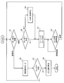
- FIG. 6 is a flowchart showing a first control method in the case where the operation switch of the electric parking brake is fixed in the on state in the vehicle control device shown in FIG. 1.
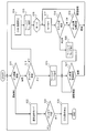
- FIG. 7 is a flowchart showing a second control method in the case where the operation switch of the electric parking brake is fixed in the on state in the vehicle control device shown in FIG. 1.
- FIG. 1 is a schematic block diagram of a control device for a vehicle.
- an electric parking brake is taken as an example of an electrical component to be controlled, and an ECU for controlling the same and its peripheral portion are extracted and shown.
- This vehicle control device includes a plurality of ECUs (control devices) 2-1, 2-2, 2-3, 2-4,... Mutually connected via a CAN bus 1 a and 1 b for in-vehicle network. ing.
- the ECU 2-1 is for the electric parking brake 3 and controls the drive of the actuator 4 that performs braking and release of the electric parking brake 3.
- the ECU 2-1 is configured to include a CAN communication integrated circuit (IC) 11, an OR gate 12, a wakeup circuit 13, a power supply IC 14, a microcomputer 15, an operation switch (external switch) 16 of the electric parking brake 3, and the like.
- the ECU 2-1 is provided with a power supply terminal T1, an IGN terminal T2, CAN-H, CAN-L terminals T3 and T4, switch terminals T5 and T6, and the like. Power is supplied to the power supply terminal T1 from the battery BA.
- a signal IGN indicating the state of the ignition key (ignition switch) is input to the IGN terminal T2.
- the CAN-H and CAN-L terminals T3 and T4 are connected to the CAN buses 1a and 1b, respectively.
- the operating switch 16 is connected between the switch terminals T5 and T6.
- the CAN communication IC 11 is supplied with power from the power supply terminal T1, and under the control of the microcomputer 15, performs data communication according to the CAN protocol from the CAN-H and CAN-L terminals T3 and T4 via the CAN buses 1a and 1b.
- the microcomputer 15 controls reception, transmission, state setting, and the like by the CAN communication IC 11.
- the CAN communication IC 11 outputs the CAN wakeup signal CWU to the OR gate 12.
- the OR gate 12 receives a signal IWU indicating the state of the ignition key from the IGN terminal T2, a wakeup signal SWU interlocked with the state of the operation switch 16 from the operation switch 16, and a self-holding signal SHS from the microcomputer 15. .
- the wakeup circuit 13 wakes up the sleep state microcomputer 15 based on the logical product signal output from the OR gate 12.
- the wakeup circuit 13 supplies power from the power supply terminal T1 to the power supply IC 14 through the current path of a semiconductor switch element controlled on / off based on the output signal of the OR gate 12, for example, the P channel type MOSFET 17. ing.
- the microcomputer 15 monitors the signal IGN indicating the state of the ignition key input from the IGN terminal T2, and monitors the wakeup signal SWU input from the switch terminal T6.
- the activation switch 16 is connected between the power supply terminal T1 and one input terminal of the OR gate 12 and supplies a high level wakeup signal SWU to the OR gate 12 when turned on.
- the operation switch 16 is connected to the power supply terminal T1 of the ECU 2-1, but may be connected directly to the vehicle-side power supply line.
- the wakeup circuit 13 supplies power to the microcomputer 15 via the power supply IC 14 to operate.
- the microcomputer 15 monitors the state of the operation switch 16 and, if instructed to brake the electric parking brake, drives the actuator 4 via the drive circuit (not shown) to brake the electric parking brake 3 Set to state.
- the microcomputer 15 further outputs a high level self-holding signal SHS to the OR gate 12 to hold the operating state of the ECU 2-1.
- the activation switch 16 instructs the electric parking brake to be released
- the microcomputer 15 causes the actuator 4 to be driven via a drive circuit or the like (not shown). Is driven to set the electric parking brake 3 in the released state.
- the electric parking brake 3 is set to the released state also when it is detected that the engine is started and the shift operation or the subsequent accelerator operation is performed. Do.
- the microcomputer 15 diagnoses whether or not the operation switch 16 of the electric parking brake 3 is stuck on (step S1).
- the microcomputer 15 monitors a wakeup signal of the switch terminal T6 (wakeup signal of the ECU 2-1 that controls the electric parking brake 3) SWU, and the wakeup signal SWU is high for a predetermined time Diagnose on-stick when continuing the level.
- the on / off determination of the ignition key is performed (step S2).
- the on / off determination of the ignition key is performed by monitoring the signal IGN input from the IGN terminal T2 by the microcomputer 15.
- step S3 When it is determined that the ignition key is turned on, for example, a warning lamp is turned on to notify the driver and draw attention (step S3).
- the operation On the other hand, when it is determined that the operation is off, that is, when the operation switch 16 of the electric parking brake 3 in the ECU 2-1 is on and the ignition key is off, the ECU 2-1 to the ECU 2-2, 2-3, 2 Data transmission (CAN transmission) to -4, ... is stopped (step S4), or the ECU 2-1 is set to the reception limited mode.
- the ECU having the CAN wakeup function in the ECUs 2-2, 2-3, 2-4,... Is suppressed from being woken up due to the on adherence of the operation switch 16 of the electric parking brake 3, Stop the operation of all ECUs 2-2, 2-3, 2-4, ... in the vehicle except ECU 2-1. Thereafter, the process proceeds to step S3 and the warning lamp is turned on.
- step S5 a return diagnosis of the on-sticking is performed. While the on-fixation continues, return diagnosis is performed, and when it returns, the process returns to step S1.
- the warning lamp continues to light, and the current consumption increases. Therefore, when the fixing is continued for a fixed number of times or for a fixed time while the ignition is off, the storage device in the ECU 2-1 (not shown) The warning lamp may be turned off after leaving a failure record in.
- step S6 When it is determined in step S1 that the on-fixation does not occur, the normal operation mode is set (step S6). In the normal operation mode, it is possible to transmit and receive data by the CAN protocol. Next, it is determined whether the ignition key is on or off (step S7). If the switch is on, the process moves to step S1 to repeat the above-described operation. If the switch is off, the microcomputer 15 stops (sleeps) the operation of the ECU 2-1 and ends the process.
- the operation switch 16 of the electric parking brake 3 when the operation switch 16 of the electric parking brake 3 is fixed on, the CAN from the ECU 2-1 to the ECU 2-2, 2-3, 2-4,. Since transmission is stopped or the ECU 2-1 is set to the reception limited mode, it is possible to suppress that the ECU for another device having a CAN wakeup function is in the operation continuation state. As a result, it is possible to reduce the dark current when the ignition is off, and to suppress the occurrence of the battery exhaustion that the operation switch 16 continues to be stuck on. Moreover, since the additional circuit and the like are unnecessary, the increase in cost can be suppressed.
- the microcomputer 15 diagnoses whether or not the operation switch 16 of the electric parking brake 3 is stuck on (step S11).
- the diagnosis of the on adherence of the operation switch 16 is performed by monitoring the wakeup signal SWU of the switch terminal T6 by the microcomputer 15 and diagnosing it as being on when the high level is continued for a predetermined time.
- the on / off determination of the ignition key is performed (step S12).
- the on / off determination of the ignition key is performed by monitoring the signal IGN input from the IGN terminal T2 by the microcomputer 15.
- the warning lamp is turned on (step S13).
- the ECU 2-1 to the ECU 2-2, 2-3, 2 Data transmission (CAN transmission) to -4, ... is stopped (step S14).
- the ECU 2-1 is set to the reception limited mode.
- the ECU having the CAN wakeup function in the ECUs 2-2, 2-3, 2-4,... Is suppressed from being woken up due to the on adherence of the operation switch 16 of the electric parking brake 3, Stop the operation of all ECUs 2-2, 2-3, 2-4, ... in the vehicle except ECU 2-1. Thereafter, the warning lamp is turned on (step S15).
- step S16 the count value N of the counter is set to the initial value 0 (step S16), and since the on-fixation is detected, it is counted up to "N + 1" (step S17). Subsequently, it is determined whether the count value N is smaller than a predetermined value M (step S18). If "N ⁇ M”, return diagnosis of on-sticking is performed (step S19). While the on-fixation continues, the process returns to step S17, the count value N is counted up "N + 1", and then the count value determination and the return diagnosis are performed. If it determines with having returned by step S19, it will return to step S11.
- step S18 If it is determined in step S18 that "N ⁇ M”, the warning lamp is turned off (step S20). If the warning lamp is turned on in step 13 or if the warning lamp is turned off in step S20, the process proceeds to step 21 to perform a recovery diagnosis of the on-stickiness (step S21). While the on-fixation continues, return diagnosis is performed, and when it returns, the process returns to step S11.
- step S11 When it is determined in step S11 that the on-fixation does not occur, the normal operation mode is set (step S22). In the normal operation mode, it is possible to transmit and receive data by the CAN protocol. Next, it is determined whether the ignition key is on or off (step S23). If it is on, the process moves to step S11 to repeat the above-described operation, and if it is off, the microcomputer 15 stops (sleeps) the operation of the ECU 2-1 and ends the process.
- the warning lamp is turned off when the on-fixing continues M times or more, so the warning lamp does not continue to light
- the current consumption can be further reduced, and the risk of battery drain can be further reduced.
- the vehicle control device including the ECU for controlling the electric parking brake has been described as an example, but the present invention is not limited to the embodiment described above, and a range not departing from the gist It is possible to carry out a modification with. That is, in a vehicle control device including a plurality of ECUs connected by a vehicle-mounted network such as CAN, when the operation switch of the electrical component controlled by the specific ECU is fixed on and the ignition key is off, the ECU Stop sending data to other ECUs. Alternatively, the ECU is set to the reception limited mode.
- 1a, 1b CAN bus, 2-1, 2-2, 2-3, 2-4: ECU (control device), 3: electric parking brake (electric component), 4: actuator, 11: CAN communication IC, 12 ... OR gate, 13 ... wake up circuit, 14 ... power supply IC, 15 ... microcomputer, 16 ... actuation switch
Landscapes
- Engineering & Computer Science (AREA)
- Mechanical Engineering (AREA)
- Transportation (AREA)
- General Physics & Mathematics (AREA)
- Signal Processing (AREA)
- Physics & Mathematics (AREA)
- Computer Networks & Wireless Communication (AREA)
- Aviation & Aerospace Engineering (AREA)
- Radar, Positioning & Navigation (AREA)
- Remote Sensing (AREA)
- Automation & Control Theory (AREA)
- Regulating Braking Force (AREA)
- Valves And Accessory Devices For Braking Systems (AREA)
- Control Of Transmission Device (AREA)
Abstract
Description
しかしながら、上述した電動パーキングブレーキにあっては、作動スイッチがオン状態で固着(オン固着と称する)すると、ウェイクアップ信号がハイレベルに固定され、電動パーキングブレーキ用のECUを動作停止(スリープ)状態にできない虞がある。
この問題は、電動パーキングブレーキに限らず、車載ネットワークで接続された複数のECUを備える車両用制御装置において、電装品の作動スイッチがオン状態で固着すると発生する。
図1は、車両用制御装置の概略構成図である。図1では、制御対象の電装品として電動パーキングブレーキを例に取り、これを制御するECUとその周辺部を抽出して示している。この車両用制御装置は、車載ネットワーク用のCANバス1a,1bを介して相互に接続された複数のECU(制御装置)2-1,2-2,2-3,2-4,…を備えている。ECU2-1は、電動パーキングブレーキ3用であり、電動パーキングブレーキ3の制動と解除を行うアクチュエータ4の駆動を制御する。
ここで、オン固着が続くとワーニングランプが点灯し続け、消費電流が増加するので、イグニッションオフ時に一定回数、または一定時間固着が継続した場合には、ECU2-1内の記憶装置(図示せず)に故障記録を残した上でワーニングランプを消灯するようにしても良い。
すなわち、CANなどの車載ネットワークで接続された複数のECUを備える車両用制御装置において、特定のECUで制御される電装品の作動スイッチがオン固着し、且つイグニッションキーがオフの場合に、当該ECUから他のECUへのデータ送信を停止させる。あるいは当該ECUを受信限定モードに設定する。
Claims (17)
- 電装品を制御する第1の制御装置と、この第1の制御装置と車載ネットワークで接続された第2の制御装置とを備え、
前記第1の制御装置における電装品の作動スイッチがオン状態で固着し、且つイグニッションキーがオフの場合に、前記第1の制御装置から前記第2の制御装置へのデータ送信を停止、あるいは前記第1の制御装置を受信限定モードに設定する、ことを特徴とする車両用制御装置。 - 前記電装品は、電動パーキングブレーキである、ことを特徴とする請求項1に記載の車両用制御装置。
- 前記車載ネットワークは、controller area network(CAN)である、ことを特徴とする請求項1に記載の車両用制御装置。
- 前記作動スイッチのオン状態での固着の判定は、当該作動スイッチのオンによって発生する前記第1の制御装置のウェイクアップ信号が所定時間継続したときに固着と判定する、ことを特徴とする請求項1に記載の車両用制御装置。
- 前記第1の制御装置は、ウェイクアップ機能を有するelectronic control unit(ECU)であり、前記第2の制御装置は、ウェイクアップ機能を有する少なくとも一つのECUを含む、ことを特徴とする請求項1に記載の車両用制御装置。
- 前記第1の制御装置は、CAN通信integrated circuit(IC)と、オアゲートと、ウェイクアップ回路と、電源ICと、マイクロコンピュータとを含む、ことを特徴とする請求項1に記載の車両用制御装置。
- 前記CAN通信ICは、CANバスを介して前記第2の制御装置とデータ通信を行う、ことを特徴とする請求項6に記載の車両用制御装置。
- 前記オアゲートは、前記CAN通信ICから出力されるCANウェイクアップ信号、イグニッションキーの状態を示す信号、前記作動スイッチの状態に連動するウェイクアップ信号、及び前記マイクロコンピュータから自己保持信号が入力され、前記ウェイクアップ回路を制御する、ことを特徴とする請求項6に記載の車両用制御装置。
- 前記ウェイクアップ回路は、前記オアゲートの出力信号に基づき、前記電源ICから前記マイクロコンピュータに電源を供給して前記第1の制御装置をスリープ状態からウェイクアップさせる、ことを特徴とする請求項6に記載の車両用制御装置。
- 前記ウェイクアップ回路は、電流通路が電源端子と前記電源IC間に接続され、前記オアゲートの出力信号に基づきオン/オフ制御される半導体スイッチ素子を含む、ことを特徴とする請求項9に記載の車両用制御装置。
- 前記電装品は、電動パーキングブレーキであり、
前記マイクロコンピュータは、前記作動スイッチの状態をモニタし、当該作動スイッチが前記電動パーキングブレーキの制動を指示していれば、前記電動パーキングブレーキを制動状態に設定する、ことを特徴とする請求項9に記載の車両用制御装置。 - 前記電動パーキングブレーキの制動状態は、前記マイクロコンピュータで前記電動パーキングブレーキの制動と解除を行うアクチュエータを駆動して設定することを特徴とする請求項11に記載の車両用制御装置。
- 電装品を制御する第1の制御装置と、この第1の制御装置と車載ネットワークで接続された第2の制御装置とを備える車両用制御装置の制御方法であって、
前記第1の制御装置における電装品の作動スイッチがオン状態で固着しているか否か診断すること、
前記作動スイッチがオン状態で固着していると診断されたときに、イグニッションキーのオン/オフ判定を行うこと、及び
前記イグニッションキーがオフと判定された場合に、前記第1の制御装置から前記第2の制御装置へのデータ送信を停止、あるいは前記第1の制御装置を受信限定モードに設定すること、
を具備することを特徴とする車両用制御装置の制御方法。 - 前記イグニッションキーがオンと判定された場合に、車両の運転者に報知すること、を更に備えることを特徴とする請求項13に記載の車両用制御装置の制御方法。
- 前記車両の運転者に報知することは、ワーニングランプを点灯すること、であることを特徴とする請求項14に記載の車両用制御装置の制御方法。
- 前記車両の運転者に報知することの後に、前記作動スイッチがオン状態で固着している状態から復帰したか否かの復帰診断を行うこと、を更に備えることを特徴とする請求項14に記載の車両用制御装置の制御方法。
- 復帰診断後に前記イグニッションキーがオフしたときに、所定回数または所定時間固着が継続した場合に、故障記録を残して運転者への報知を停止する、ことを特徴とする請求項16に記載の車両用制御装置の制御方法。
Priority Applications (3)
| Application Number | Priority Date | Filing Date | Title |
|---|---|---|---|
| US15/558,804 US10497189B2 (en) | 2015-03-17 | 2016-02-19 | Vehicular control device and method of controlling vehicular control device |
| CN201680016141.XA CN107428297B (zh) | 2015-03-17 | 2016-02-19 | 车辆用控制装置及其控制方法 |
| DE112016001241.1T DE112016001241B4 (de) | 2015-03-17 | 2016-02-19 | Fahrzeugsteuereinrichtung und verfahren zum steuern einer fahrzeugsteuereinrichtung |
Applications Claiming Priority (2)
| Application Number | Priority Date | Filing Date | Title |
|---|---|---|---|
| JP2015053627A JP6417248B2 (ja) | 2015-03-17 | 2015-03-17 | 車両用制御装置 |
| JP2015-053627 | 2015-03-17 |
Publications (1)
| Publication Number | Publication Date |
|---|---|
| WO2016147793A1 true WO2016147793A1 (ja) | 2016-09-22 |
Family
ID=56918784
Family Applications (1)
| Application Number | Title | Priority Date | Filing Date |
|---|---|---|---|
| PCT/JP2016/054886 Ceased WO2016147793A1 (ja) | 2015-03-17 | 2016-02-19 | 車両用制御装置及びその制御方法 |
Country Status (5)
| Country | Link |
|---|---|
| US (1) | US10497189B2 (ja) |
| JP (1) | JP6417248B2 (ja) |
| CN (1) | CN107428297B (ja) |
| DE (1) | DE112016001241B4 (ja) |
| WO (1) | WO2016147793A1 (ja) |
Families Citing this family (8)
| Publication number | Priority date | Publication date | Assignee | Title |
|---|---|---|---|---|
| JP6417249B2 (ja) * | 2015-03-17 | 2018-10-31 | 日立オートモティブシステムズ株式会社 | 車両用制御装置及び車両用制御システム |
| CN110371055B (zh) * | 2018-04-12 | 2022-09-23 | 上海汽车集团股份有限公司 | 一种汽车电源信号的解析方法及装置 |
| US11639142B2 (en) | 2019-01-11 | 2023-05-02 | Ford Global Technologies, Llc | Electronic control module wake monitor |
| CN112491671B (zh) * | 2019-09-11 | 2022-04-19 | 广州汽车集团股份有限公司 | 一种整车馈电问题监测方法、系统和汽车can网络网关 |
| JP7352166B2 (ja) * | 2019-10-31 | 2023-09-28 | 株式会社オートネットワーク技術研究所 | 車載通信システム、車載通信装置及び車両用通信方法 |
| CN111845688B (zh) * | 2020-07-09 | 2022-04-29 | 北京汽车股份有限公司 | Epb的控制方法、装置、车辆的钥匙和车辆 |
| US12164354B2 (en) * | 2020-10-07 | 2024-12-10 | Hitachi Astemo, Ltd. | Electronic control device and method for diagnosing wake-up circuit |
| CN114740814A (zh) * | 2021-01-07 | 2022-07-12 | 长沙中车智驭新能源科技有限公司 | 基于云控系统的整车控制方法、云控系统及电气架构 |
Citations (4)
| Publication number | Priority date | Publication date | Assignee | Title |
|---|---|---|---|---|
| JP4147253B2 (ja) * | 2006-04-28 | 2008-09-10 | 富士重工業株式会社 | 電動パーキングブレーキ制御装置 |
| JP2009296280A (ja) * | 2008-06-04 | 2009-12-17 | Toyota Motor Corp | 通信ネットワークシステム及びその通信制御方法 |
| JP2010254258A (ja) * | 2009-04-28 | 2010-11-11 | Toyota Motor Corp | 車両制御装置 |
| JP2012035722A (ja) * | 2010-08-06 | 2012-02-23 | Denso Corp | 車載機器制御システム |
Family Cites Families (9)
| Publication number | Priority date | Publication date | Assignee | Title |
|---|---|---|---|---|
| JP3478193B2 (ja) * | 1999-05-24 | 2003-12-15 | トヨタ自動車株式会社 | 電源監視装置 |
| JP3338679B2 (ja) * | 1999-12-09 | 2002-10-28 | 本田技研工業株式会社 | 車両の診断装置 |
| US20040113494A1 (en) * | 2000-09-01 | 2004-06-17 | Karuppana Samy V. | Daytime running light control using an intelligent power management system |
| CN1298560C (zh) * | 2003-12-30 | 2007-02-07 | 联合汽车电子有限公司 | 混合动力汽车控制系统及其控制方法 |
| WO2007113809A2 (en) * | 2006-03-30 | 2007-10-11 | Saban Asher S | Protecting children and passengers with respect to a vehicle |
| DE102007006035A1 (de) * | 2007-02-07 | 2008-08-14 | Daimler Ag | Warnlichteinrichtung für ein Fahrzeug zum Anzeigen einer Verzögerung des Fahrzeugs |
| CN102834287B (zh) * | 2010-03-25 | 2015-02-04 | 万国卡车知识产权有限公司 | 电池电源管理系统 |
| DE102011084534A1 (de) * | 2010-10-18 | 2012-04-19 | Continental Teves Ag & Co. Ohg | Fehlersichere Parkbremse für Kraftfahrzeuge |
| CN104159755B (zh) * | 2012-03-09 | 2016-08-24 | 日产自动车株式会社 | 轮胎气压监视装置 |
-
2015
- 2015-03-17 JP JP2015053627A patent/JP6417248B2/ja not_active Expired - Fee Related
-
2016
- 2016-02-19 DE DE112016001241.1T patent/DE112016001241B4/de active Active
- 2016-02-19 CN CN201680016141.XA patent/CN107428297B/zh not_active Expired - Fee Related
- 2016-02-19 US US15/558,804 patent/US10497189B2/en active Active
- 2016-02-19 WO PCT/JP2016/054886 patent/WO2016147793A1/ja not_active Ceased
Patent Citations (4)
| Publication number | Priority date | Publication date | Assignee | Title |
|---|---|---|---|---|
| JP4147253B2 (ja) * | 2006-04-28 | 2008-09-10 | 富士重工業株式会社 | 電動パーキングブレーキ制御装置 |
| JP2009296280A (ja) * | 2008-06-04 | 2009-12-17 | Toyota Motor Corp | 通信ネットワークシステム及びその通信制御方法 |
| JP2010254258A (ja) * | 2009-04-28 | 2010-11-11 | Toyota Motor Corp | 車両制御装置 |
| JP2012035722A (ja) * | 2010-08-06 | 2012-02-23 | Denso Corp | 車載機器制御システム |
Also Published As
| Publication number | Publication date |
|---|---|
| US20180075674A1 (en) | 2018-03-15 |
| JP6417248B2 (ja) | 2018-10-31 |
| CN107428297A (zh) | 2017-12-01 |
| US10497189B2 (en) | 2019-12-03 |
| DE112016001241T5 (de) | 2017-12-14 |
| DE112016001241B4 (de) | 2026-02-12 |
| JP2016172502A (ja) | 2016-09-29 |
| CN107428297B (zh) | 2020-03-17 |
Similar Documents
| Publication | Publication Date | Title |
|---|---|---|
| US10501081B2 (en) | Vehicular control device, method of controlling vehicular control device, and vehicular control system | |
| JP6417248B2 (ja) | 車両用制御装置 | |
| KR101393539B1 (ko) | 자동차 통합 네트워크 시스템 | |
| US10850685B2 (en) | Onboard relay device, information processing method, storage medium storing program, relay device, and information processing system | |
| US9764702B2 (en) | System and method for managing the electrical powering of at least one piece of equipment during the automatic restarting of an internal combustion engine of a vehicle | |
| US11444801B2 (en) | Gateway device | |
| JP2013106200A (ja) | 車両用通信中継装置、スリープ制御方法 | |
| CN104340120B (zh) | 车载负载控制系统 | |
| US9519337B2 (en) | Circuitry for controlling an output from an electronic control unit including two processors mutually monitoring each other | |
| JP6643210B2 (ja) | 車両データ読出装置及び車両データ読出方法 | |
| CN106257292A (zh) | 故障诊断控制方法及系统 | |
| JP2003063330A (ja) | 車両の電源供給制御装置 | |
| CN111439224A (zh) | 车载系统、无线通信装置以及控制方法 | |
| JP6458150B2 (ja) | 電子制御装置 | |
| KR20150052186A (ko) | 통신 채널에 연결된 장치를 모니터링하는 방법 | |
| US12095588B2 (en) | Vehicular drawing device | |
| JP4737030B2 (ja) | 車両用発電制御装置 | |
| CN109661653B (zh) | 机动车辆的车载计算机的重启的控制装置 | |
| JP6956797B2 (ja) | 判定装置、判定システム及び判定方法 | |
| JP2014169021A (ja) | 車載制御システム | |
| WO2026023440A1 (ja) | 車載システム | |
| JP6747205B2 (ja) | 車両用制御装置 | |
| CN117549744A (zh) | 车辆控制方法、装置以及车辆 | |
| CN119428492A (zh) | 车辆的异常唤醒故障诊断方法、系统及车辆 |
Legal Events
| Date | Code | Title | Description |
|---|---|---|---|
| 121 | Ep: the epo has been informed by wipo that ep was designated in this application |
Ref document number: 16764623 Country of ref document: EP Kind code of ref document: A1 |
|
| WWE | Wipo information: entry into national phase |
Ref document number: 15558804 Country of ref document: US |
|
| WWE | Wipo information: entry into national phase |
Ref document number: 112016001241 Country of ref document: DE |
|
| 122 | Ep: pct application non-entry in european phase |
Ref document number: 16764623 Country of ref document: EP Kind code of ref document: A1 |
|
| WWG | Wipo information: grant in national office |
Ref document number: 112016001241 Country of ref document: DE |