WO2016147782A1 - 膜厚測定装置および膜厚測定方法 - Google Patents
膜厚測定装置および膜厚測定方法 Download PDFInfo
- Publication number
- WO2016147782A1 WO2016147782A1 PCT/JP2016/054509 JP2016054509W WO2016147782A1 WO 2016147782 A1 WO2016147782 A1 WO 2016147782A1 JP 2016054509 W JP2016054509 W JP 2016054509W WO 2016147782 A1 WO2016147782 A1 WO 2016147782A1
- Authority
- WO
- WIPO (PCT)
- Prior art keywords
- film
- film thickness
- light
- reflected light
- monochromatic
- Prior art date
- Legal status (The legal status is an assumption and is not a legal conclusion. Google has not performed a legal analysis and makes no representation as to the accuracy of the status listed.)
- Ceased
Links
Images



Classifications
-
- G—PHYSICS
- G01—MEASURING; TESTING
- G01B—MEASURING LENGTH, THICKNESS OR SIMILAR LINEAR DIMENSIONS; MEASURING ANGLES; MEASURING AREAS; MEASURING IRREGULARITIES OF SURFACES OR CONTOURS
- G01B11/00—Measuring arrangements characterised by the use of optical techniques
- G01B11/02—Measuring arrangements characterised by the use of optical techniques for measuring length, width or thickness
- G01B11/06—Measuring arrangements characterised by the use of optical techniques for measuring length, width or thickness for measuring thickness ; e.g. of sheet material
-
- G—PHYSICS
- G01—MEASURING; TESTING
- G01B—MEASURING LENGTH, THICKNESS OR SIMILAR LINEAR DIMENSIONS; MEASURING ANGLES; MEASURING AREAS; MEASURING IRREGULARITIES OF SURFACES OR CONTOURS
- G01B11/00—Measuring arrangements characterised by the use of optical techniques
- G01B11/02—Measuring arrangements characterised by the use of optical techniques for measuring length, width or thickness
- G01B11/06—Measuring arrangements characterised by the use of optical techniques for measuring length, width or thickness for measuring thickness ; e.g. of sheet material
- G01B11/0616—Measuring arrangements characterised by the use of optical techniques for measuring length, width or thickness for measuring thickness ; e.g. of sheet material of coating
- G01B11/0625—Measuring arrangements characterised by the use of optical techniques for measuring length, width or thickness for measuring thickness ; e.g. of sheet material of coating with measurement of absorption or reflection
Definitions
- the present invention relates to a film thickness measuring device and a film thickness measuring method.
- Patent Document 1 Conventionally, a film thickness measuring device and a film thickness measuring method are known (see, for example, Patent Document 1).
- Patent Document 1 discloses a film thickness measuring apparatus and a film thickness measuring method that collectively estimate film thicknesses at a plurality of points using information of reflected light at a plurality of points on a transparent film.
- this film thickness measuring apparatus and film thickness measuring method light including monochromatic light having a plurality of wavelengths is irradiated onto a transparent film that is a measurement target. Then, a plurality of observation points are selected from the interference image generated by the reflected light from the surface of the transparent film and the reflected light from the back surface, the luminance signal of the interference image of the selected observation point, and a predetermined interference fringe model Based on the (interference fringe model for the transparent film), the film thicknesses at a plurality of points are estimated collectively.
- the film thickness measurement apparatus and the film thickness measurement method described in Patent Document 1 are configured such that the film thicknesses at a plurality of points of the transparent film are estimated collectively, while the light absorption coefficient is compared. It is desired to estimate the film thickness of a plurality of points at once for a relatively large semitransparent film.
- the present invention has been made in order to solve the above-described problems, and one object of the present invention is to provide a film thickness capable of collectively estimating film thicknesses at a plurality of points of a translucent film. It is to provide a measuring apparatus and a film thickness measuring method.
- a film thickness measuring apparatus is irradiated from a light source that irradiates light including monochromatic light of a plurality of wavelengths to a translucent film that is a measurement target,
- An imaging unit that captures an interference image generated by reflected light from the surface of the translucent film and reflected light from the back surface, i is the observation point number of the interference image captured by the imaging unit, and the type of wavelength of the monochromatic light ,
- the wavelength of monochromatic light is ⁇ (j)
- the film refractive index of the semitransparent film is n
- the luminance value observed at the observation point is g (i, j)
- the reflected light from the surface of the semitransparent film I 1 (j) the intensity of the reflected light from the back surface when there is no light absorption in the translucent film
- I 20 (j) the absorption coefficient of the translucent film is k (j), and translucent
- the thickness of the film was t (i), based on the following equation
- the “semi-transparent film” in the present invention means a film that allows light to pass therethrough but reduces the intensity of light that passes through the film (a part of the light is absorbed),
- the subject matter is a colored transparent film that absorbs a specific wavelength, or a film that contains granules or the like and has turbidity (haze).
- unknown variables I 1 (j), I 20 (j), k (j), and t (i) are estimated based on the above equation (1).
- I 1 (j), I 20 (j), k (j), and t (i) for a plurality of observation points (i) are collectively estimated. That is, unlike the case of the transparent film, the above formula (1) considering the light absorption (e ⁇ 2k (j) t (i) , e ⁇ k (j) t (i) ) by the translucent film should be used.
- the film thickness t (i) at a plurality of points of the translucent film can be estimated in a lump.
- the control unit is configured to obtain I 1 (j), I 20 (j), and k (j) obtained based on the above formula (1), and the following: Based on the equation (2), the film thickness t of the observation point other than the observation point of the interference image used when obtaining I 1 (j), I 20 (j) and k (j) is an unknown variable. It is configured to estimate.
- the above equation (1) (the number of unknown variables is I 1 (j), I 20 (j), k (j), and t (i)) are used, and the film thickness t can be estimated at a higher speed.
- the control unit sets an initial value for the unknown variable and nonlinearly minimizes the objective function based on a value calculated from the function including the unknown variable. It is configured to estimate unknown variables by programming. If comprised in this way, even when the function containing an unknown variable cannot be solved analytically (in the case of a nonlinear function), an unknown variable can be estimated.
- the film thickness measuring apparatus preferably, when the number of wavelengths of the plurality of monochromatic lights is m and the number of observation points of the interference image is N, it is unknown based on the following equation (3). It is configured to set the number N of interference image observation points for obtaining variables I 1 (j), I 20 (j), k (j), and t (i).
- the plurality of monochromatic lights include three colors of monochromatic light of blue, green, and red. If comprised in this way, since the wavelength of three colors of monochromatic light differs, the interference color produced
- the film thickness can be estimated based on the luminance value g (i, j) (or luminance value g (j)) observed at the observation point.
- the film thickness measuring method includes a step of irradiating a translucent film to be measured with light containing monochromatic light having a plurality of wavelengths, reflected light from the surface of the translucent film, and from the back surface.
- the step of capturing an interference image generated by reflected light the observation point number of the captured interference image is i, the number for the type of wavelength of the monochromatic light is j, the wavelength of the monochromatic light is ⁇ (j), and is translucent
- the film refractive index is n
- the luminance value observed at the observation point is g (i, j)
- the intensity of reflected light from the surface of the translucent film is I 1 (j)
- the light absorption in the translucent film is When the intensity of the reflected light from the back surface is I 20 (j), the absorption coefficient of the translucent film is k (j), and the thickness of the translucent film is t (i),
- the unknown variables I 1 (j), I 20 (j), k (j) and t By including the step of estimating i), I 1 (j), I 20 (j), k (j), and t (i) for a plurality of observation points (i) are collectively estimated. That is, unlike the case of the transparent film, the above formula (4) considering light absorption (e ⁇ 2k (j) t (i) , e ⁇ k (j) t (i) ) by the translucent film Can be used to collectively estimate the film thickness t (i) at a plurality of points of the semitransparent film. As a result, it is possible to estimate the film thickness t (i) at a plurality of points of the semitransparent film at a higher speed than in the case where the film thickness is estimated for each point.
- the film thicknesses at a plurality of points of the translucent film can be estimated collectively.
- the film thickness measuring apparatus 100 includes a white light source 10, a three-wavelength band filter 20, a microscope 30, a color camera 40, and a control unit 50.
- the white light source 10 and the color camera 40 are examples of the “light source” and the “imaging unit” of the present invention, respectively.
- the white light source 10 is configured to irradiate the translucent film 60 to be measured with light including monochromatic light having a plurality of wavelengths.
- the plurality of monochromatic lights include three colors of monochromatic light of blue (B), green (G), and red (R).
- the “semi-transparent film” in the present embodiment means a film that allows light to pass therethrough but reduces the intensity of light passing through the film (a part of the light is absorbed).
- the subject matter is a colored transparent film that absorbs a specific wavelength, or a film that contains granules or the like and is turbid (haze).
- the three-wavelength band filter 20 is configured to transmit monochromatic light of three colors of blue (B), green (G), and red (R) among the white light emitted from the white light source 10.
- a half mirror 31 is provided inside the microscope 30.
- the half mirror 31 is configured to irradiate the semi-transparent film 60 that is a measurement target with monochromatic light of three colors of blue (B), green (G), and red (R) that has passed through the three-wavelength band filter 20. Has been.
- the color camera 40 is configured to capture an interference image that is emitted from the white light source 10 and is generated by reflected light from the surface of the translucent film 60 and reflected light from the back surface.
- the color camera 40 is configured by, for example, a CCD (Charge Coupled Device) image sensor, a CMOS (Complementary Metal Oxide Semiconductor) image sensor, or the like.
- the control unit 50 sets the observation point number of the interference image to i, the number for the type of wavelength of the monochromatic light, j, the wavelength of the monochromatic light to ⁇ (j), and the film refraction of the translucent film 60.
- the rate is n
- the luminance value observed at the observation point is g (i, j)
- the intensity of the reflected light from the surface of the translucent film 60 is I 1 (j)
- no light is absorbed in the translucent film 60.
- the control unit 50 In the case where the intensity of reflected light from the back surface is I 20 (j), the absorption coefficient of the semitransparent film 60 is k (j), and the film thickness of the semitransparent film 60 is t (i), 9), I 1 (j), I 20 (j), k (j) and t (i) are configured to be estimated. Further, the control unit 50, I 1 obtained based on the equation (9) described later (j), on the basis of the I 20 (j) and k (j), described below equations (19), I 1 (J), I 20 (j) and k (j) are configured to estimate the film thickness t of observation points other than the observation point of the interference image used when obtaining k (j) as an unknown variable. Specifically, the control unit 50 sets an initial value for the unknown variable, and estimates the unknown variable by nonlinear programming that minimizes the objective function based on a value calculated from the function including the unknown variable. It is configured as follows. Details will be described below.
- the interference between the reflected light from the surface of the translucent film 60 and the reflected light from the back surface is expressed by the following formula (5) if multiple reflections are ignored.
- I 1 and I 2 represent the intensity (light quantity) of reflected light from the front surface and the intensity (light quantity) of reflected light from the back surface, respectively.
- ⁇ represents the wavelength of light irradiated on the semitransparent film 60, and ⁇ represents the phase difference between the reflected light from the front surface and the reflected light from the back surface.
- the refractive index of the translucent film 60 is smaller than the refractive index of the substrate 61 (see FIG. 1) on which the translucent film 60 is placed (film refractive index ⁇ substrate refractive index), the above formula In (6), the sign of the third term on the right side is positive (+).
- the intensity I 2 of the reflected light from the back surface of the semitransparent film 60 is expressed by the following equation (7) according to Lambert-Beer's law, where k is the absorption coefficient of the semitransparent film 60.
- the horizontal axis represents the film thickness (nm) and the vertical axis represents the luminance value.
- the wavelength (period) becomes longer in the order of blue (B), green (G), and red (R).
- the luminance value decreases as the film thickness increases.
- the upper part of FIG. 2 represents a color chart of interference colors for each film thickness (nm). That is, the upper part of FIG. 2 shows colors obtained by adding blue (B), green (G), and red (R) in the lower part of FIG. In the upper part of FIG. 2, gray shades are shown, but in actuality, the colors are interference colors. In this way, different interference colors are obtained for each film thickness.
- GMFT Global Model Fitting for Thickness
- the model luminance value g (i, j) of the interference fringes is expressed by the following equation (9) by modifying the above equation (8).
- the intensity I 1 (j) of the reflected light from the surface of the semitransparent film 60 the intensity I 20 (j) of the reflected light from the back surface of the semitransparent film 60 when there is no absorption, and the semitransparent
- the absorption coefficient k (j) of the film 60 is assumed to be a constant without depending on the observation point. This assumption is generally valid if the structure of the semitransparent film 60 to be estimated is the same (uniform) and the light emitted from the white light source 10 is uniform.
- unknown variables I 1 (j) and I 20 (I 20 () are based on the model luminance value g (i, j) of the interference fringes and the luminance values observed at a plurality of points.
- j), k (j) and t (i) are configured to be estimated.
- unknown variables (parameters) I 1 (j), I 20 (j), k (j) are obtained by nonlinear programming (least-squares method) that minimizes the sum of squared errors of the following equation (10).
- t (i) are estimated.
- g (i, j) represents the model luminance value of the above equation (9), and g ij represents the observed luminance value.
- the estimation (measurement) algorithm is schematically represented as shown in FIG. That is, 3N observed luminance values (g (1, B), g (1, G), g (1, R), ..., g (N, B), g (N, G), g ( N, R)) to N film thicknesses (t (1),..., T (N)) and nine parameters (I 1 (B), I 1 (G), I 1 (R) ), I 20 (B), I 20 (G), I 20 (R), k (B), k (G), k (R)).
- the model luminance value of the above equation (9) includes a cosine function (cos function) that is a periodic function, when the least square method is used in the estimation algorithm of the present embodiment, the local minimum value (local minimum) is There are many. Therefore, it is necessary to set an appropriate initial value.
- the median value a and the amplitude b of the luminance value are obtained by the following equations (12) and (13), respectively.
- max represents the maximum luminance value
- min represents the minimum value
- the ⁇ sign depends on the magnitude relationship between I 1 and I 20 .
- This magnitude relationship can be obtained by the following equation (18) derived from the Fresnel equation.
- n represents the refractive index of the translucent film 60
- n B represents the refractive index of the substrate 61 a semi-transparent film 60 is placed.
- k (j) has no periodicity, so there is no problem because the initial value is “0”.
- t (i) since t (i) is in the cos function, it has periodicity. Therefore, the initial value of t (i) is set to an accurate initial value from a priori information.
- luminance matching method an algorithm for estimating one unknown variable t will be described.
- This algorithm is called luminance matching method.
- the remaining one unknown variable t is estimated using the three unknown variables I 1 , I 20 , and k estimated by the GMFT method.
- the film thickness t of the observation point other than the observation point of the interference image used when obtaining I 1 (j), I 20 (j) and k (j) is estimated as an unknown variable.
- t is an unknown variable based on the model luminance value g (j) of the interference fringes and the observed luminance value. That is, the unknown variable t (i) is estimated by a non-linear programming method that minimizes the sum of squared errors of the following equation (20).
- g (j) represents the model luminance value of the above equation (19), and g j represents the observed luminance value.
- the model luminance value g (j) in the above equation (19) includes a periodic function, there are many local minimum values (local minimum) when nonlinear programming is used. Therefore, in a general nonlinear programming method, the solution converges to a local solution near the initial value, and a correct solution may not be obtained. Therefore, in this embodiment, a multi-start method is used. That is, a plurality of solutions are obtained by using a nonlinear programming method, starting from a plurality of initial values having a preset step interval within the range of the expected film thickness. Then, a solution that minimizes the sum of squared errors is adopted as a global solution from a plurality of obtained solutions.
- the film thickness t (i) of the translucent film 60 is estimated using the above formula (9) or formula (19), a relatively complicated optical system such as a spectroscope or a polarizing optical system is used. As a result, it is possible to simplify the configuration of the film thickness measuring apparatus 100.
- the film thickness t (i) can be estimated without using a conversion table (calibration data) from the captured image (interference color) to the film thickness.
- the film thickness t (i) can be estimated for each observation point (that is, for each pixel of the interference image), it is possible to configure the film thickness measuring apparatus 100 with a relatively high horizontal resolution.
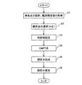
- step S ⁇ b> 1 monochromatic light having a plurality of wavelengths (blue, green, red) is transmitted from the white light source 10 to the translucent film 60 to be measured via the three-wavelength band filter 20 and the half mirror 31.
- the light containing is irradiated.
- membrane 60 and the reflected light from a back surface is imaged with the color camera 40, and an observation luminance value is acquired.
- step S2 the number of observation points determined based on the above equation (11) is selected.
- step S3 initial values of unknown variables I 1 (j), I 20 (j), k (j), and t (i) are set.
- step S4 unknown variables I 1 (j), I 20 (j), k (j), and t (i) are estimated based on the GMFT method (the above equation (9)). .
- I 1 (j), I 20 (j), k (j), and t (i) for a plurality of observation points (i) are collectively estimated. That is, the film thicknesses t (i) at a plurality of points of the semitransparent film 60 are estimated collectively.
- step S5 using I 1 (j), I 20 (j), and k (j) estimated by the GMFT method, a desired matching method is obtained based on the luminance matching method (the above equation (19)).
- An unknown variable t at the observation point is estimated.
- a plurality of solutions can be obtained by using a multi-start method (starting from a plurality of initial values).
- step S6 a solution having the smallest sum of squared errors (that is, a global solution) is adopted (estimated) as the film thickness from the plurality of obtained solutions.
- the color chart shown in the upper part of FIG. 2 has 200 pixels in the horizontal direction.
- the Solver (registered trademark) function of Excel (registered trademark) manufactured by Microsoft Corporation was used as the nonlinear programming method (specifically, the least square method).
- the luminance matching method (the above formula (19)) is used by using unknown variables I 1 (j), I 20 (j), and k (j) estimated by the GMFT method. ) To estimate the film thickness t at 200 observation points in the horizontal direction of the color chart.
- the multi-start method with a step interval of 100 nm was adopted assuming that the range of the film thickness t of the translucent film 60 was 1000 nm.
- the control unit that estimates the unknown variables I 1 (j), I 20 (j), k (j), and t (i) based on the equation (9). 50 is provided.
- I 1 (j), I 20 (j), k (j), and t (i) for a plurality of observation points (i) are collectively estimated. That is, unlike the case of the transparent film, the above formula (9) is used in consideration of light absorption (e ⁇ 2k (j) t (i) , e ⁇ k (j) t (i) ) by the semitransparent film 60.
- the film thicknesses t (i) at a plurality of points of the translucent film 60 can be estimated collectively.
- the film thickness t of the observation point other than the observation point of the interference image used when obtaining I 1 (j), I 20 (j) and k (j) is estimated as an unknown variable.
- the number of unknown variables is one of the film thickness t, so that the above equation (9) (the number of unknown variables is I 1 (j), I 20 (j) , K (j) and t (i) (3m + N)), the film thickness t can be estimated at higher speed.
- the initial value is set for the unknown variable, and the unknown variable is determined by nonlinear programming that minimizes the objective function based on the value calculated from the function including the unknown variable.
- the control unit 50 is configured to estimate. Thereby, even when a function including an unknown variable cannot be solved analytically (in the case of a nonlinear function), the unknown variable can be estimated.
- the unknown variable is based on the above equation (11).
- the number N of interference image observation points for obtaining I 1 (j), I 20 (j), k (j), and t (i) is set.
- the minimum number of interference image observation points required for the unknown variable can be easily obtained based on the above equation (11).
- the plurality of monochromatic lights include three monochromatic lights of blue, green, and red.
- the interference color generated by the interference of the three colors of monochromatic light varies depending on the film thickness.
- the film thickness can be estimated based on the luminance value g (i, j) (or luminance value g (j)) observed at the observation point.
- the semitransparent film may be irradiated with light from a light source that emits blue, green, and red monochromatic light.
- the present invention is not limited to this.
- luminance values of observation points other than six may be used as long as the above equation (11) is satisfied.
- the multi-start method starts from a plurality of initial values
- the present invention is not limited to this.
- the film thickness may be estimated from one initial value.
Landscapes
- Physics & Mathematics (AREA)
- General Physics & Mathematics (AREA)
- Length Measuring Devices By Optical Means (AREA)
- Investigating Or Analysing Materials By Optical Means (AREA)
Abstract
Description




を用いることにより、半透明膜の複数の点の膜厚t(i)を一括して推定することができる。その結果、1点ごとに膜厚を推定する場合と比べて、高速に半透明膜の複数の点の膜厚t(i)を推定することができる。
(膜厚測定装置の構成)
図1を参照して、本実施形態による膜厚測定装置100の構成について説明する。
〈半透明膜における干渉色と膜厚との関係〉
ます、半透明膜60における干渉色と膜厚との関係について説明する。


次に、未知変数I1、I20、kおよびtを推定するアルゴリズムについて説明する。このアルゴリズムを、GMFT(Global Model Fitting for Thickness)法と呼ぶ。



および(15)が得られる。



次に、1つの未知変数tを推定するアルゴリズムについて説明する。このアルゴリズムを輝度合致法と呼ぶ。輝度合致法では、GMFT法により推定された3つの未知変数I1、I20、kを用いて、残りの1つの未知変数tが推定される。


次に、図4を参照して、本実施形態による膜厚測定方法について説明する。
次に、図5~図8を参照して、GMFT法および輝度合致法の妥当性を確認するための実験について説明する。
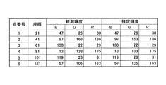
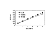
図5に示すように、6個の観測点(点番号1~6)の全てにおいて、青(B)、緑(G)および赤(R)の単色光の全てについて、観測された輝度値と、上記の式(9)により推定された輝度値とが、完全に一致した。
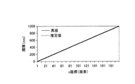
図8に示すように、水平方向に沿った200個の観測点(x座標1~200)の全ておいて、推定された膜厚と真値とが、完全に一致した。これにより、輝度合致法が、未知変数t(i)の推定に有効であることが確認された。なお、推定された膜厚と真値とが完全に一致しているため、図8では、推定された膜厚の線と真値の線とが重なって表示されている。
次に、本実施形態の効果について説明する。
なお、今回開示された実施形態および実施例は、すべての点で例示であって制限的なものではないと考えられるべきである。本発明の範囲は、上記した実施形態および実施例の説明ではなく特許請求の範囲によって示され、さらに特許請求の範囲と均等の意味および範囲内でのすべての変更(変形例)が含まれる。
40 カラーカメラ(撮像部)
50 制御部
60 半透明膜
100 膜厚測定装置
Claims (6)
- 測定対象である半透明膜に複数の波長の単色光を含む光を照射する光源と、
前記光源から照射され、前記半透明膜の表面からの反射光と裏面からの反射光とにより生成される干渉画像を撮像する撮像部と、
前記撮像部により撮像された前記干渉画像の観測点番号をi、前記単色光の波長の種類に対する番号をj、前記単色光の波長をλ(j)、前記半透明膜の膜屈折率をn、前記観測点において観測された輝度値をg(i,j)、前記半透明膜の表面からの反射光の強さをI1(j)、前記半透明膜における光の吸収がない場合の裏面からの反射光の強さをI20(j)、前記半透明膜の吸収係数をk(j)、前記半透明膜の膜厚をt(i)とした場合、以下の式(1)に基づいて、未知変数であるI1(j)、I20(j)、k(j)およびt(i)を推定する制御部とを備える、膜厚測定装置。

- 前記制御部は、上記の式(1)に基づいて求められたI1(j)、I20(j)およびk(j)と、以下の式(2)とに基づいて、I1(j)、I20(j)およびk(j)を求める際に用いられた前記干渉画像の観測点以外の観測点の膜厚tを未知変数として推定するように構成されている、請求項1に記載の膜厚測定装置。

- 前記制御部は、前記未知変数に初期値を設定するとともに、前記未知変数を含む関数から算出される値に基づいて、目的関数を最小化する非線形計画法により、前記未知変数を推定するように構成されている、請求項1または2に記載の膜厚測定装置。
- 前記複数の単色光の波長の数をm、前記干渉画像の観測点の数をNとした場合、以下の式(3)に基づいて、前記未知変数であるI1(j)、I20(j)、k(j)およびt(i)を求めるための前記干渉画像の観測点の数Nを設定するように構成されている、請求項1または3に記載の膜厚測定装置。

- 前記複数の単色光は、青、緑および赤の3色の単色光を含む、請求項1に記載の膜厚測定装置。
- 測定対象である半透明膜に複数の波長の単色光を含む光を照射する工程と、
前記半透明膜の表面からの反射光と裏面からの反射光とにより生成される干渉画像を撮像する工程と、
撮像された前記干渉画像の観測点番号をi、前記単色光の波長の種類に対する番号をj、前記単色光の波長をλ(j)、前記半透明膜の膜屈折率をn、前記観測点において観測された輝度値をg(i,j)、前記半透明膜の表面からの反射光の強さをI1(j)、前記半透明膜における光の吸収がない場合の裏面からの反射光の強さをI20(j)、前記半透明膜の吸収係数をk(j)、前記半透明膜の膜厚をt(i)とした場合、以下の式(4)に基づいて、未知変数であるI1(j)、I20(j)、k(j)およびt(i)を推定する工程とを備える、膜厚測定方法。

Priority Applications (2)
| Application Number | Priority Date | Filing Date | Title |
|---|---|---|---|
| US15/558,016 US10274307B2 (en) | 2015-03-17 | 2016-02-17 | Film thickness measurement device using interference of light and film thickness measurement method using interference of light |
| JP2017506152A JP6564848B2 (ja) | 2015-03-17 | 2016-02-17 | 膜厚測定装置および膜厚測定方法 |
Applications Claiming Priority (2)
| Application Number | Priority Date | Filing Date | Title |
|---|---|---|---|
| JP2015053539 | 2015-03-17 | ||
| JP2015-053539 | 2015-03-17 |
Publications (1)
| Publication Number | Publication Date |
|---|---|
| WO2016147782A1 true WO2016147782A1 (ja) | 2016-09-22 |
Family
ID=56918880
Family Applications (1)
| Application Number | Title | Priority Date | Filing Date |
|---|---|---|---|
| PCT/JP2016/054509 Ceased WO2016147782A1 (ja) | 2015-03-17 | 2016-02-17 | 膜厚測定装置および膜厚測定方法 |
Country Status (3)
| Country | Link |
|---|---|
| US (1) | US10274307B2 (ja) |
| JP (1) | JP6564848B2 (ja) |
| WO (1) | WO2016147782A1 (ja) |
Cited By (1)
| Publication number | Priority date | Publication date | Assignee | Title |
|---|---|---|---|---|
| US20210356254A1 (en) * | 2018-11-09 | 2021-11-18 | Kabushiki Kaisha Kobe Seiko Sho (Kobe Steel, Ltd.) | Device and method for measuring oxide film thickness |
Families Citing this family (4)
| Publication number | Priority date | Publication date | Assignee | Title |
|---|---|---|---|---|
| JP7481090B2 (ja) * | 2019-01-09 | 2024-05-10 | 株式会社ディスコ | 厚み計測装置、及び厚み計測装置を備えた加工装置 |
| KR20210116271A (ko) * | 2020-03-17 | 2021-09-27 | 도쿄엘렉트론가부시키가이샤 | 막 두께 측정 시스템 및 막 두께 측정 방법 |
| JP7431694B2 (ja) * | 2020-07-28 | 2024-02-15 | キヤノン株式会社 | 情報処理装置、膜形成装置、物品の製造方法、およびプログラム |
| KR20230132671A (ko) * | 2022-03-08 | 2023-09-18 | 삼성디스플레이 주식회사 | 표시패널의 제조방법 |
Citations (4)
| Publication number | Priority date | Publication date | Assignee | Title |
|---|---|---|---|---|
| JPH0763524A (ja) * | 1993-08-24 | 1995-03-10 | Jasco Corp | 薄膜評価方法および評価装置 |
| JPH0771924A (ja) * | 1993-09-01 | 1995-03-17 | Hitachi Ltd | 薄膜特性値測定方法及び装置 |
| US6392756B1 (en) * | 1999-06-18 | 2002-05-21 | N&K Technology, Inc. | Method and apparatus for optically determining physical parameters of thin films deposited on a complex substrate |
| JP2013145229A (ja) * | 2011-12-16 | 2013-07-25 | Toray Eng Co Ltd | 干渉色のモデル適合による膜厚測定方法およびその装置 |
Family Cites Families (1)
| Publication number | Priority date | Publication date | Assignee | Title |
|---|---|---|---|---|
| US4785336A (en) * | 1986-12-04 | 1988-11-15 | Libbey-Owens-Ford Co. | Device for monitoring characteristics of a film on a substrate |
-
2016
- 2016-02-17 US US15/558,016 patent/US10274307B2/en not_active Expired - Fee Related
- 2016-02-17 WO PCT/JP2016/054509 patent/WO2016147782A1/ja not_active Ceased
- 2016-02-17 JP JP2017506152A patent/JP6564848B2/ja not_active Expired - Fee Related
Patent Citations (4)
| Publication number | Priority date | Publication date | Assignee | Title |
|---|---|---|---|---|
| JPH0763524A (ja) * | 1993-08-24 | 1995-03-10 | Jasco Corp | 薄膜評価方法および評価装置 |
| JPH0771924A (ja) * | 1993-09-01 | 1995-03-17 | Hitachi Ltd | 薄膜特性値測定方法及び装置 |
| US6392756B1 (en) * | 1999-06-18 | 2002-05-21 | N&K Technology, Inc. | Method and apparatus for optically determining physical parameters of thin films deposited on a complex substrate |
| JP2013145229A (ja) * | 2011-12-16 | 2013-07-25 | Toray Eng Co Ltd | 干渉色のモデル適合による膜厚測定方法およびその装置 |
Non-Patent Citations (1)
| Title |
|---|
| KATSUICHI KITAGAWA ET AL.: "Wide-view Transparent Film Thickness Measurement System by Interference Color Analysis", JOURNAL OF THE JAPAN SOCIETY OF PRECISION ENGINEERING, vol. 79, 5 January 2014 (2014-01-05), pages 1078 - 1082, XP055311991, [retrieved on 20130000] * |
Cited By (2)
| Publication number | Priority date | Publication date | Assignee | Title |
|---|---|---|---|---|
| US20210356254A1 (en) * | 2018-11-09 | 2021-11-18 | Kabushiki Kaisha Kobe Seiko Sho (Kobe Steel, Ltd.) | Device and method for measuring oxide film thickness |
| US11761752B2 (en) * | 2018-11-09 | 2023-09-19 | Kobe Steel, Ltd. | Device and method for measuring oxide film thickness |
Also Published As
| Publication number | Publication date |
|---|---|
| US10274307B2 (en) | 2019-04-30 |
| US20180045506A1 (en) | 2018-02-15 |
| JP6564848B2 (ja) | 2019-08-21 |
| JPWO2016147782A1 (ja) | 2017-12-28 |
Similar Documents
| Publication | Publication Date | Title |
|---|---|---|
| JP6564848B2 (ja) | 膜厚測定装置および膜厚測定方法 | |
| JP5424143B2 (ja) | 反射度分布曲線のモデリング方法及びこれを利用した厚さ測定方法、ならびに厚さ測定反射計 | |
| JP2017044596A (ja) | 膜厚測定装置および膜厚測定方法 | |
| JP6284705B2 (ja) | 干渉色のモデル適合による膜厚測定方法およびその装置 | |
| JP2019020183A (ja) | 膜厚測定方法及び膜厚測定装置 | |
| TWI567364B (zh) | 結構光產生裝置、量測系統及其方法 | |
| JP5942356B2 (ja) | 分光情報取得装置、分光情報取得方法及び分光情報取得用プログラム | |
| KR101672537B1 (ko) | 광학 파라미터를 이용한 3차원 객체 렌더링 장치 | |
| WO2019124104A1 (ja) | 物体形状計測装置、および方法、並びにプログラム | |
| JP2015230264A (ja) | 膜厚測定方法および膜厚測定装置 | |
| CN115451820B (zh) | 三通道偏振信息采集系统 | |
| Zhu et al. | Three-dimensional measurement of fringe projection based on the camera response function of the polarization system | |
| Elek et al. | Robust and practical measurement of volume transport parameters in solid photo-polymer materials for 3D printing | |
| Schäfer et al. | Model based scattering correction in time-of-flight cameras | |
| JP5997578B2 (ja) | クロストーク補正係数算出方法およびクロストーク補正係数算出機能を備えた透明膜の膜厚測定装置 | |
| US20140374603A1 (en) | Profilometry systems and methods based on absorption and optical frequency conversion | |
| Kim et al. | Generating a true color image with data from scanning white-light interferometry by using a Fourier transform | |
| TWI598565B (zh) | 測量薄膜厚度的方法 | |
| JP6862229B2 (ja) | 解析装置、撮像装置、解析方法、および、プログラム | |
| WO2019238583A1 (en) | Deflectometric techniques | |
| JP2006113022A (ja) | 反射防止フィルムの欠陥検出装置および方法 | |
| JP2018159557A (ja) | 膜厚測定装置および膜厚測定方法 | |
| Ma et al. | In-motion 3D reconstruction of high dynamic range surfaces | |
| JP2005221368A5 (ja) | ||
| Falco | High-resolution infrared imaging |
Legal Events
| Date | Code | Title | Description |
|---|---|---|---|
| 121 | Ep: the epo has been informed by wipo that ep was designated in this application |
Ref document number: 16764612 Country of ref document: EP Kind code of ref document: A1 |
|
| ENP | Entry into the national phase |
Ref document number: 2017506152 Country of ref document: JP Kind code of ref document: A |
|
| WWE | Wipo information: entry into national phase |
Ref document number: 15558016 Country of ref document: US |
|
| NENP | Non-entry into the national phase |
Ref country code: DE |
|
| 122 | Ep: pct application non-entry in european phase |
Ref document number: 16764612 Country of ref document: EP Kind code of ref document: A1 |