WO2016147658A1 - 有機物質分解用触媒、その製造方法および有機物質の低分子化方法 - Google Patents
有機物質分解用触媒、その製造方法および有機物質の低分子化方法 Download PDFInfo
- Publication number
- WO2016147658A1 WO2016147658A1 PCT/JP2016/001476 JP2016001476W WO2016147658A1 WO 2016147658 A1 WO2016147658 A1 WO 2016147658A1 JP 2016001476 W JP2016001476 W JP 2016001476W WO 2016147658 A1 WO2016147658 A1 WO 2016147658A1
- Authority
- WO
- WIPO (PCT)
- Prior art keywords
- catalyst
- organic substance
- outer shell
- shell layer
- converter dust
- Prior art date
- Legal status (The legal status is an assumption and is not a legal conclusion. Google has not performed a legal analysis and makes no representation as to the accuracy of the status listed.)
- Ceased
Links
Images

Classifications
-
- B—PERFORMING OPERATIONS; TRANSPORTING
- B01—PHYSICAL OR CHEMICAL PROCESSES OR APPARATUS IN GENERAL
- B01J—CHEMICAL OR PHYSICAL PROCESSES, e.g. CATALYSIS OR COLLOID CHEMISTRY; THEIR RELEVANT APPARATUS
- B01J23/00—Catalysts comprising metals or metal oxides or hydroxides, not provided for in group B01J21/00
- B01J23/70—Catalysts comprising metals or metal oxides or hydroxides, not provided for in group B01J21/00 of the iron group metals or copper
- B01J23/76—Catalysts comprising metals or metal oxides or hydroxides, not provided for in group B01J21/00 of the iron group metals or copper combined with metals, oxides or hydroxides provided for in groups B01J23/02 - B01J23/36
- B01J23/78—Catalysts comprising metals or metal oxides or hydroxides, not provided for in group B01J21/00 of the iron group metals or copper combined with metals, oxides or hydroxides provided for in groups B01J23/02 - B01J23/36 with alkali- or alkaline earth metals
-
- B—PERFORMING OPERATIONS; TRANSPORTING
- B01—PHYSICAL OR CHEMICAL PROCESSES OR APPARATUS IN GENERAL
- B01J—CHEMICAL OR PHYSICAL PROCESSES, e.g. CATALYSIS OR COLLOID CHEMISTRY; THEIR RELEVANT APPARATUS
- B01J35/00—Catalysts, in general, characterised by their form or physical properties
- B01J35/50—Catalysts, in general, characterised by their form or physical properties characterised by their shape or configuration
- B01J35/51—Spheres
- B01J35/52—Hollow spheres
-
- B—PERFORMING OPERATIONS; TRANSPORTING
- B01—PHYSICAL OR CHEMICAL PROCESSES OR APPARATUS IN GENERAL
- B01J—CHEMICAL OR PHYSICAL PROCESSES, e.g. CATALYSIS OR COLLOID CHEMISTRY; THEIR RELEVANT APPARATUS
- B01J37/00—Processes, in general, for preparing catalysts; Processes, in general, for activation of catalysts
- B01J37/08—Heat treatment
-
- B—PERFORMING OPERATIONS; TRANSPORTING
- B09—DISPOSAL OF SOLID WASTE; RECLAMATION OF CONTAMINATED SOIL
- B09B—DISPOSAL OF SOLID WASTE NOT OTHERWISE PROVIDED FOR
- B09B3/00—Destroying solid waste or transforming solid waste into something useful or harmless
- B09B3/30—Destroying solid waste or transforming solid waste into something useful or harmless involving mechanical treatment
- B09B3/35—Shredding, crushing or cutting
-
- C—CHEMISTRY; METALLURGY
- C02—TREATMENT OF WATER, WASTE WATER, SEWAGE, OR SLUDGE
- C02F—TREATMENT OF WATER, WASTE WATER, SEWAGE, OR SLUDGE
- C02F11/00—Treatment of sludge; Devices therefor
- C02F11/10—Treatment of sludge; Devices therefor by pyrolysis
-
- C—CHEMISTRY; METALLURGY
- C08—ORGANIC MACROMOLECULAR COMPOUNDS; THEIR PREPARATION OR CHEMICAL WORKING-UP; COMPOSITIONS BASED THEREON
- C08J—WORKING-UP; GENERAL PROCESSES OF COMPOUNDING; AFTER-TREATMENT NOT COVERED BY SUBCLASSES C08B, C08C, C08F, C08G or C08H
- C08J11/00—Recovery or working-up of waste materials
- C08J11/04—Recovery or working-up of waste materials of polymers
- C08J11/10—Recovery or working-up of waste materials of polymers by chemically breaking down the molecular chains of polymers or breaking of crosslinks, e.g. devulcanisation
- C08J11/16—Recovery or working-up of waste materials of polymers by chemically breaking down the molecular chains of polymers or breaking of crosslinks, e.g. devulcanisation by treatment with inorganic material
-
- Y—GENERAL TAGGING OF NEW TECHNOLOGICAL DEVELOPMENTS; GENERAL TAGGING OF CROSS-SECTIONAL TECHNOLOGIES SPANNING OVER SEVERAL SECTIONS OF THE IPC; TECHNICAL SUBJECTS COVERED BY FORMER USPC CROSS-REFERENCE ART COLLECTIONS [XRACs] AND DIGESTS
- Y02—TECHNOLOGIES OR APPLICATIONS FOR MITIGATION OR ADAPTATION AGAINST CLIMATE CHANGE
- Y02P—CLIMATE CHANGE MITIGATION TECHNOLOGIES IN THE PRODUCTION OR PROCESSING OF GOODS
- Y02P20/00—Technologies relating to chemical industry
- Y02P20/50—Improvements relating to the production of bulk chemicals
- Y02P20/52—Improvements relating to the production of bulk chemicals using catalysts, e.g. selective catalysts
-
- Y—GENERAL TAGGING OF NEW TECHNOLOGICAL DEVELOPMENTS; GENERAL TAGGING OF CROSS-SECTIONAL TECHNOLOGIES SPANNING OVER SEVERAL SECTIONS OF THE IPC; TECHNICAL SUBJECTS COVERED BY FORMER USPC CROSS-REFERENCE ART COLLECTIONS [XRACs] AND DIGESTS
- Y02—TECHNOLOGIES OR APPLICATIONS FOR MITIGATION OR ADAPTATION AGAINST CLIMATE CHANGE
- Y02W—CLIMATE CHANGE MITIGATION TECHNOLOGIES RELATED TO WASTEWATER TREATMENT OR WASTE MANAGEMENT
- Y02W30/00—Technologies for solid waste management
- Y02W30/50—Reuse, recycling or recovery technologies
- Y02W30/62—Plastics recycling; Rubber recycling
Definitions
- the present invention relates to a catalyst used for thermally decomposing an organic substance such as waste plastic to reduce the molecular weight (gasification or oil conversion), a method for producing the catalyst, and a method for reducing the molecular weight of the organic substance.
- FCC catalyst mainly composed of zeolite, silica alumina, etc.
- transition metal catalyst mainly composed of Fe, Ni, etc.
- noble metal catalyst mainly composed of Pt, Rh, etc.
- Patent Document 1 discloses a method in which waste plastic and FCC catalyst are charged into a reaction tank, gasified at a temperature of 350 to 500 ° C., and cooled to obtain an oil component.
- FCC catalysts composed of synthetic zeolite and the like are expensive, and thus there is a problem that the processing cost becomes high. For this reason, use of an inexpensive catalyst is required.
- Patent Document 2 discloses a method of thermally decomposing a low molecular weight organic substance such as waste plastic by bringing it into contact with a specific mixed gas (a mixed gas obtained by reforming a steelworks byproduct gas) in a fluidized bed. It has been shown that converter dust generated in the steel making process is used as a catalyst (which is also a fluidized medium in a fluidized bed), and this converter dust is an inexpensive catalyst.
- Patent Document 2 uses a mixed gas obtained by reforming a steelworks by-product gas as a reaction gas, and uses ironworks converter dust as a catalyst. It is possible to implement.
- the gasification rate ratio of the amount of carbon contained in the produced gas out of the amount of input carbon
- silica sand having no catalytic effect is used as a fluid medium.
- an object of the present invention is to solve the above-described problems of the prior art and to fully exhibit the catalytic effect of the iron content contained in the converter dust, which is a catalyst for organic substance decomposition obtained from the converter dust. It is an object of the present invention to provide a catalyst for decomposing organic materials, a method for producing the same, and a method for reducing the molecular weight of organic materials.
- the present inventors have conducted detailed studies on the reason why the catalytic effect cannot be sufficiently obtained when converter dust is used as a catalyst for decomposing organic substances, and countermeasures.
- the present inventors have a small catalytic effect of converter dust because iron oxide, which is effective as a catalyst, is covered with an outer shell layer (outermost layer) mainly composed of a calcium compound. It has been found that the catalytic effect of iron oxide contained in converter dust can be sufficiently exerted by removing the outer shell layer mainly composed of this calcium compound. Also, even if the outer shell layer mainly composed of the calcium compound remains, the outer shell layer is modified so that it can be easily peeled off when used as a catalyst for decomposing organic substances. It was also found that the desired catalytic effect can be obtained.
- a method for producing a catalyst for decomposing organic substances from converter dust generated at a steelworks Prepare converter dust, For decomposing organic substances, removing at least a part of the outer shell layer (a) mainly composed of calcium compounds from the converter dust and exposing the iron oxide layer (b) under the outer shell layer (a)
- a method for producing a catalyst [2] The method for producing an organic substance decomposition catalyst according to [1], wherein the converter dust is heat-treated in an oxidizing atmosphere to peel off at least a part of the outer shell layer (a).
- a method for producing a catalyst for decomposing organic substances from converter dust generated at a steel works, Prepare converter dust, A method for producing a catalyst for decomposing an organic substance, wherein the converter dust is heat-treated in an oxidizing atmosphere to reform at least a part of the outer shell layer (a) containing a calcium compound as a main component so as to be easily peeled off.
- a catalyst for decomposing an organic substance having an outer shell layer (a) and an iron oxide layer (b) in order from the surface The outer shell layer (a) is mainly composed of a calcium compound,
- the iron oxide layer (b) is an organic substance decomposition catalyst in which at least a part is exposed.
- a catalyst for decomposing an organic substance having an outer shell layer (a) and an iron oxide layer (b) in order from the surface The outer shell layer (a) is mainly composed of a calcium compound, The organic oxide decomposition catalyst, wherein the iron oxide layer (b) is modified so that at least a part thereof is easily peeled off.
- a method for reducing the molecular weight of an organic substance using the organic substance decomposition catalyst according to [5] or [6] Prepare an organic substance and organic substance decomposition catalyst, The organic substance is brought into contact with the reaction gas in the presence of the organic substance decomposition catalyst, and the organic substance is brought into contact with the reaction gas in the presence of the organic substance decomposition catalyst that is reduced in molecular weight by thermal decomposition.
- the catalyst for decomposing an organic substance of the present invention is obtained by removing at least a part of the outer shell layer (a) mainly composed of a calcium compound covering the surface of the converter dust, and forming a lower layer of the outer shell layer (a).
- the iron oxide layer (b) can be effectively functioned as a catalyst because the iron oxide layer (b) is exposed or at least part of the outer shell layer (a) is easily detached during use as a catalyst.
- the catalytic effect of iron oxide contained in the converter dust can be sufficiently exhibited.
- the gasification rate of organic substances can be greatly improved, and a large amount of inexpensive and highly active catalysts can be obtained. It is possible to use and produce fuel from organic substances at low cost.
- FIG. 1 is an SEM observation image of a cross section of untreated converter dust particles
- (B) is an SEM observation image of a cross section of converter dust particles from which a part of the outer shell layer has been removed by oxidation treatment. It is.
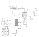
- FIG. 2 is an explanatory diagram showing an outline of the fluidized bed gasification test apparatus used in the examples.
- the present inventors have embedded the converter dust in a resin, and SEM- Observed with EDX.
- components were also identified by wide-angle XDR analysis.
- the particle structure of the converter dust has metallic iron at the center, and this metallic iron is covered with an iron oxide layer such as FeO and Fe 3 O 4 , and a calcium compound is mainly used as the outermost layer. It became clear that it was covered with the outer shell layer as a component.
- Converter dust is generated when the hot metal splashed during converter refining is made into droplets by surface tension, and flux (CaO (calcium oxide)) is mainly formed on the droplet surface during the generation. It is considered that the outer shell layer is formed as described above.
- the iron oxide layer effective as a catalyst is covered with an outer shell layer mainly composed of a calcium compound, and the effective effective catalyst surface area is reduced, so that a sufficient catalytic effect is obtained. It was estimated that it was not possible.
- the present inventors performed oxidation treatment on the converter dust to remove the outer shell layer mainly composed of a calcium compound, and examined the catalytic effect of the converter dust. As a result, it was found that by removing the outer shell layer, the effective catalyst surface area of the converter dust was greatly increased, and the gasification rate of the organic substance was improved when used as a catalyst.
- FIGS. 1A and 1B show SEM observation images of cross-sections of untreated converter dust and converter dust particles from which a part of the outer shell layer has been removed by oxidation treatment.
- Converter dust is obtained by classifying the converter dust generated at an iron mill by air classification and removing a particle size of 40 ⁇ m or less.
- Fig. 1 (A) shows unprocessed converter dust
- Fig. 1 (B) shows that converter dust is put in a stainless steel bat and heat-treated (oxidation treatment) at 650 ° C for 30 minutes in an electric furnace in an air atmosphere. It is a thing. As shown in FIGS.
- the converter dust has metallic iron at the center, and this metallic iron is an iron oxide layer (in FIG. 1A, FeO + Fe 3 O 4 , FIG. 1B ) Is covered with Fe 2 O 3 + Fe 3 O 4 ), but the untreated converter dust in FIG. 1 (A) has an outer shell in which the entire iron oxide layer is mainly composed of a calcium compound (calcium hydroxide). Covered with layers.
- the oxidized converter dust in FIG. 1 (B) has a part of the outer shell layer mainly composed of a calcium compound (calcium hydroxide is changed to calcium carbonate by the oxidation treatment). It is removed and the underlying iron oxide layer is exposed on the dust surface.
- Converter dust is iron-containing dust that has been collected and collected by converter refining in the steelmaking process, and has a high component ratio of iron among the dust generated in steelworks, and is a catalyst for decomposing organic substances that is inexpensive and available in large quantities. (Including the case where it is used as a fluid medium having a catalytic function).
- Examples of the steelmaking process in which converter dust is generated include, but are not limited to, a dephosphorization process, a decarburization process, a stainless steel refining process, and the like.
- the outer shell layer a of converter dust is mainly composed of a calcium compound derived from a flux (that is, containing 50% by mass or more of calcium compound), and includes a case of being composed only of a calcium compound.
- the calcium compound contained in the outer shell layer a is at least one of Ca (OH) 2 , CaO, and CaCO 3 .
- Components other than the calcium compound as the main component are derived from components other than Ca in the flux, hot metal, slag, and the like.
- the outer shell layer a mainly composed of the calcium compound of the converter dust is removed, and the iron oxide layer b under the removed outer shell layer a is removed as dust. It is exposed on the surface.
- the outer shell layer a mainly composed of the calcium compound of the converter dust is removed, and the organic oxide decomposition in which the iron oxide layer b below the removed outer shell layer a is exposed on the dust surface.
- the catalyst for use is obtained.
- the outer shell layer a is peeled off by heat treatment (oxidation treatment) of the converter dust in an oxidizing atmosphere.
- B a method in which the outer shell layer a is dissolved by treating the converter dust with an acid solution, and (c) a calcium compound (Ca (OH) constituting the outer shell layer a by heating the converter dust.
- a method of peeling the outer shell layer a by crushing mechanically after making the state easy to peel by desorbing the moisture in 2 ) can be applied.
- the method (a) is preferable because it can be carried out easily and at low cost.
- the above “at least part” preferably has a removal rate of 20% by volume or more. That is, the outer shell layer a removed from the iron oxide layer b is 20% by volume or more (removal rate: 20%) with respect to the total amount (volume%) of the outer shell layer a formed on the iron oxide layer b before the removal. (Volume% or more) is preferable.
- the above removal rate can be measured by image analysis of 10 or more particles from an SEM photograph observed at a magnification of 800 times.
- the outer shell layer a is peeled off by heat treating (oxidizing) the converter dust in an oxidizing atmosphere.
- the outer shell layer a is formed by the heat treatment.
- the OH group of the calcium compound (Ca (OH) 2 ) is eliminated and the outer shell layer a is cracked, and the outer shell layer a is easily peeled off.
- Heat treatment in an oxidizing atmosphere (oxidation treatment) ) Fe 3 O 4 in the converter dust is oxidized to Fe 2 O 3 and the crystal structure changes from cubic to hexagonal and shrinks, so the iron oxide layer b shrinks relative to the outer shell layer a.
- the interface between the iron oxide layer b and the outer shell layer a is peeled off.
- the converter dust from which a part of the outer shell layer a is peeled and removed by such an action is used in the process of being used as a catalyst for decomposing organic matter even if the outer shell layer a that does not peel remains. a further peels and contributes to the improvement of the catalytic effect. In particular, when used in a fluidized bed, peeling of the outer shell layer a is promoted by contact with other particles.
- the oxidizing atmosphere for heat treating the converter dust may be an atmosphere (gas composition, temperature condition) that can oxidize FeO to Fe 3 O 4 or Fe 2 O 3 .
- CO 2 can be used as a gas for promoting oxidation
- an air atmosphere is desirable in order to perform the treatment at a low cost.
- the heat treatment temperature is preferably 600 to 900 ° C. When the heat treatment temperature is less than 600 ° C., the oxidation rate is slow. On the other hand, when the heat treatment temperature exceeds 900 ° C., the iron oxide exposed by the peeling of the outer shell layer a may be sintered with dust and firmly fixed.
- the heat treatment time is preferably 15 minutes or more.
- a heat treatment method batch-type heat treatment using an electric furnace is possible, but in the case of continuous treatment as an industrial process, it is preferable to use a rotary kiln.
- the outer shell layer a and the iron oxide layer b are formed in order from the surface by the first manufacturing method, and the outer shell layer a is mainly composed of the calcium compound, and the iron oxide layer b. It is possible to obtain a catalyst for decomposing organic substances in which at least a part of the catalyst is exposed.
- the converter dust can be modified so that at least a part of the outer shell layer a is easily peeled even if the outer shell layer a mainly composed of the calcium compound still exists. .
- the outer shell layer a easily peels off, and a desired catalytic effect is obtained.
- the converter dust is heat-treated in an oxidizing atmosphere (oxidation treatment) to modify at least a part of the outer shell layer a so as to be easily peeled off. .
- a catalyst for decomposing an organic substance which has been modified so that at least a part of the outer shell layer a containing a calcium compound as a main component is easily peeled, is obtained.
- the above “easy to peel” refers to a state where the outer shell layer a covers the iron oxide layer b while the outer shell layer a is cracked.
- said "at least one part" in a 2nd manufacturing method is also 20 volume% or more as a removal rate. That is, the outer shell layer a removed from the iron oxide layer b is 20% by volume or more (removal rate: 20%) with respect to the total amount (volume%) of the outer shell layer a formed on the iron oxide layer b before the removal. (Volume% or more) is preferable.
- the removal rate can be measured by image analysis of 10 or more particles from an SEM photograph observed at a magnification of 800 times after the outer shell layer a peels from the iron oxide layer b.
- the organic substance decomposition catalyst obtained in the present invention is used for reducing the molecular weight (gasification / oilification) by thermal decomposition by bringing an organic substance into contact with a reaction gas. That is, in the method for reducing the molecular weight of an organic substance according to the present invention, the organic substance is brought into contact with a reaction gas in the presence of the organic substance decomposition catalyst to reduce the molecular weight by pyrolysis (gasification or oilification). To do.
- the organic substance (solid) that is subject to thermal decomposition but high molecular weight organic substances are suitable, for example, resins (usually resin waste such as waste plastics), biomass, etc. One or more of these can be targeted.
- the resins include polyolefins such as PE and PP, thermoplastic polyesters such as PA and PET, elastomers such as PS, thermosetting resins, synthetic rubbers and foamed polystyrene. It is not limited to.
- examples of biomass include, but are not limited to, sewage sludge, paper, wood (for example, construction waste wood, packaging / transport waste wood, thinned wood, etc.).
- reaction vessel in which an organic substance and a reaction gas are brought into contact with each other in the presence of an organic substance decomposition catalyst.
- a horizontal moving bed reactor such as a rotary kiln
- a vertical reactor filled with a catalyst A fluidized bed reactor can be used, and among these, a fluidized bed reactor is particularly preferable from the viewpoint of processing efficiency.
- the organic substance decomposition catalyst obtained in the present invention is used as at least a part of the fluidized medium, the organic substance is brought into contact with the reaction gas in the fluidized bed of the fluidized medium, and the organic substance is heated. Decompose to lower molecular weight (gasification or oil conversion).
- the type of reaction gas to be brought into contact with the organic substance is not particularly limited, and is not limited to a known gasifying agent, for example, a mixed gas shown in Patent Document 2 (exhaust gas containing carbon monoxide generated in a metallurgical furnace).
- a mixed gas shown in Patent Document 2 exhaust gas containing carbon monoxide generated in a metallurgical furnace.
- the converter dust generated at the steelworks is classified by wind, and the particle size of 40 ⁇ m or less is removed and placed in a stainless steel bat, and oxidized in the air furnace in the air atmosphere under the conditions shown in Table 1 and shown in FIG. 1 (B).
- disassembly consisting of the converter dust from which a part of outer shell layer a to show and the lower iron oxide layer b exposed was exposed was obtained.
- waste plastic gasification tests (Examples 1 and 2 of the present invention) were carried out using the organic substance decomposition catalyst as a fluidized medium.
- 1 is a fluidized bed type pyrolysis furnace, and 2 is a fluidized bed.
- the pyrolysis furnace 1 is formed above a fluidized bed 2 formed of a fluidized medium, a windbox portion 5 into which fluidized gas is introduced from a gas supply pipe 3, and a windbox portion 5, And a dispersion plate 4 that blows upward.
- a flowing gas gasification agent
- a fluidized bed 2 made of a fluidized medium is formed above the substrate.
- the organic substance put into the pyrolysis furnace 1 is pyrolyzed in the fluidized bed 2 to become a gas product.
- the gas containing the gaseous product is discharged through the discharge pipe 6.
- the organic substance put in the hopper 7 is cut out by the table feeder 8 and falls from the upper part of the pyrolysis furnace 1 to the fluidized bed 2.
- the flowing gas (gasification agent) supplies water from the tank 9 to the steam generator 10 by the pump 11 to generate steam, and N 2 , H 2 and CO 2 are added to the steam from the gas cylinders 12, 13 and 14.
- steam is prepared, and this flowing gas (mixed gas of H 2 O, N 2 , H 2 , CO 2 ) is introduced into the pyrolysis furnace 1 through the gas supply pipe 3.
- the gas cooler 15 is a gas trap
- the gas flow rate is continuously measured by the mass flow meter 16, and further the gas chromatography.
- the gas composition is measured.
- the lower gas calorific value and gasification rate were determined from the gas generation amount and gas composition.
- the results are shown in Table 1 together with the converter dust oxidation conditions.
- the gasification rate is obtained by the following equation, and the “gasification raw material” is waste plastic particles.
- F ⁇ (G ⁇ C2-V ⁇ C3) / (M ⁇ C1) ⁇ ⁇ 100
- M Gasification raw material supply amount (kg / h)
- V Gasification agent supply amount (kg / h)
- G Amount of generated gas (kg / h)
- C1 Carbon concentration in gasification raw material (%)
- C2 Carbon concentration in product gas (%)
- C3 Carbon concentration in gasifying agent (%)
Landscapes
- Chemical & Material Sciences (AREA)
- Engineering & Computer Science (AREA)
- Organic Chemistry (AREA)
- Chemical Kinetics & Catalysis (AREA)
- Materials Engineering (AREA)
- Environmental & Geological Engineering (AREA)
- Life Sciences & Earth Sciences (AREA)
- Thermal Sciences (AREA)
- Physics & Mathematics (AREA)
- Hydrology & Water Resources (AREA)
- Water Supply & Treatment (AREA)
- Sustainable Development (AREA)
- Health & Medical Sciences (AREA)
- Medicinal Chemistry (AREA)
- Polymers & Plastics (AREA)
- Separation, Recovery Or Treatment Of Waste Materials Containing Plastics (AREA)
- Catalysts (AREA)
- Processing Of Solid Wastes (AREA)
- Treatment Of Sludge (AREA)
Abstract
転炉ダストから得られる有機物質分解用触媒であって、転炉ダストが含有する鉄分による触媒効果を十分に発揮することができる有機物質分解用触媒を得る。 転炉ダストからカルシウム化合物を主成分とする外殻層(a)の少なくとも一部を除去し、外殻層(a)の下層の酸化鉄層(b)をダスト表面に露出させる。好ましくは、転炉ダストを酸化雰囲気中で熱処理して、外殻層(a)の少なくとも一部を剥離する。転炉ダストから外殻層(a)を除去すると、触媒として有効に機能できる酸化鉄層の表面積が増加し、転炉ダストは、該転炉ダストが含有する酸化鉄による触媒効果を十分に発揮する。
Description
本発明は、廃プラスチックなどの有機物質を熱分解して低分子化(ガス化または油化)する際に用いる触媒とその製造方法と有機物質の低分子化方法に関する。
近年、エネルギー問題が大きな課題となっており、これを解決するための一つのアプローチとして、有機物質が有する熱量を有効に活用する方法が考えられている。特に、廃プラスチックを初めとする樹脂系廃棄物は発熱量が高く、化石燃料代替の燃料として有効に活用できる可能性がある。しかしながら、樹脂系廃棄物は熱伝導性が悪く昇温に時間がかかるため、燃焼速度が非常に遅く、固体のままでは燃料代替として用いることが難しい。そこで、樹脂類を分解し、ガスや油分に変換してから燃料として用いる手法が考えられている。樹脂系廃棄物のガス化・油化には熱分解法を用いることが可能であるが、この方法では熱分解を促進するための触媒が使用される。この触媒としては、ゼオライト、シリカアルミナなどを主体とするFCC触媒、Fe、Niなどを主体とする遷移金属系触媒、Pt、Rhなどを主成分とする貴金属系触媒などを使用できることが知られている。
例えば、特許文献1には、廃プラスチックとFCC触媒を反応槽に投入した後、350~500℃の温度でガス化し、これを冷却して油分を得る方法が示されている。しかし、合成ゼオライトなどで構成されるFCC触媒は高価であるため処理コストが高くなる問題があり、このため安価な触媒の使用が求められている。
特許文献2には、廃プラスチックなどの有機物質を流動層内で特定の混合ガス(製鉄所副生ガスを改質した混合ガス)と接触させることで熱分解して低分子化する方法において、触媒(流動層の流動媒体でもある)として製鋼工程で発生する転炉ダストを使用することが示されており、この転炉ダストは安価な触媒であるといえる。
特許文献2には、廃プラスチックなどの有機物質を流動層内で特定の混合ガス(製鉄所副生ガスを改質した混合ガス)と接触させることで熱分解して低分子化する方法において、触媒(流動層の流動媒体でもある)として製鋼工程で発生する転炉ダストを使用することが示されており、この転炉ダストは安価な触媒であるといえる。
特許文献2に示す方法は、製鉄所副生ガスを改質した混合ガスを反応用ガスとして使用し、また製鉄所転炉ダストを触媒として使用するため、有機物質の低分子化を低コストに実施することが可能である。しかしながら、この方法には、触媒効果を有しない珪砂を流動媒体として用いた場合と比較して、ガス化率(投入された炭素量のうち生成ガスに含まれる炭素量の比率)があまり改善されないという課題があった。つまり、触媒が有効に働いていないことが推測される。
したがって本発明の目的は、以上のような従来技術の課題を解決し、転炉ダストから得られる有機物質分解用触媒であって、転炉ダストが含有する鉄分による触媒効果を十分に発揮することができる有機物質分解用触媒とその製造方法と有機物質の低分子化方法を提供することにある。
本発明者らは、上記課題を解決するために、転炉ダストを有機物質分解用触媒として用いた際に触媒効果が十分に得られない理由と、その対策について詳細な検討を行った。その結果、本発明者らは、転炉ダストの触媒効果が小さいのは、触媒として有効である酸化鉄がカルシウム化合物を主成分とする外殻層(最外層)で覆われているためであり、このカルシウム化合物を主成分とする外殻層を取り除くことにより、転炉ダストが含有する酸化鉄による触媒効果を十分に発揮させることができることを見出した。また、カルシウム化合物を主成分とする外殻層が存在したままであっても、その外殻層を、有機物質分解用触媒として使用した際に容易に剥離できるような状態に改質しておくことにより、所望の触媒効果が得られることも判った。
本発明は、このような知見に基づきなされたもので、以下を要旨とするものである。
[1]製鉄所で発生する転炉ダストから有機物質分解用触媒を製造する方法であって、
転炉ダストを準備し、
前記転炉ダストから、カルシウム化合物を主成分とする外殻層(a)の少なくとも一部を除去し、前記外殻層(a)の下層の酸化鉄層(b)を露出させる有機物質分解用触媒の製造方法。
[2]上記[1]の製造方法において、前記転炉ダストを酸化雰囲気中で熱処理して、前記外殻層(a)の少なくとも一部を剥離する有機物質分解用触媒の製造方法。
[3]製鉄所で発生する転炉ダストから有機物質分解用触媒を製造する方法であって、
転炉ダストを準備し、
前記転炉ダストを酸化雰囲気中で熱処理して、カルシウム化合物を主成分とする外殻層(a)の少なくとも一部を剥離しやすい状態に改質する有機物質分解用触媒の製造方法。
[4]上記[2]または[3]の製造方法において、酸化雰囲気のロータリーキルン内で前記転炉ダストを熱処理する有機物質分解用触媒の製造方法。
[5]表面から順に、外殻層(a)と酸化鉄層(b)とを有する有機物質分解用触媒であって、
前記外殻層(a)は、カルシウム化合物を主成分とし、
前記酸化鉄層(b)は、少なくとも一部が露出している有機物質分解用触媒。
[6]表面から順に、外殻層(a)と酸化鉄層(b)とを有する有機物質分解用触媒であって、
前記外殻層(a)は、カルシウム化合物を主成分とし、
前記酸化鉄層(b)は、少なくとも一部が剥離しやすい状態に改質されている有機物質分解用触媒。
[7]上記[5]または[6]に記載の有機物質分解用触媒を用いた有機物質の低分子化方法であって、
有機物質及び有機物質分解用触媒を準備し、
前記有機物質分解用触媒の存在下、前記有機物質を反応用ガスと接触させて、熱分解で低分子化する有機物質分解用触媒の存在下、有機物質を反応用ガスと接触させることにより熱分解で低分子化する有機物質の低分子化方法。
[8]上記[7]の低分子化方法において、流動媒体が前記有機物質分解用触媒を含む流動層を準備し、
前記流動層において、前記有機物質を前記反応用ガスと接触させる有機物質の低分子化方法。
[1]製鉄所で発生する転炉ダストから有機物質分解用触媒を製造する方法であって、
転炉ダストを準備し、
前記転炉ダストから、カルシウム化合物を主成分とする外殻層(a)の少なくとも一部を除去し、前記外殻層(a)の下層の酸化鉄層(b)を露出させる有機物質分解用触媒の製造方法。
[2]上記[1]の製造方法において、前記転炉ダストを酸化雰囲気中で熱処理して、前記外殻層(a)の少なくとも一部を剥離する有機物質分解用触媒の製造方法。
[3]製鉄所で発生する転炉ダストから有機物質分解用触媒を製造する方法であって、
転炉ダストを準備し、
前記転炉ダストを酸化雰囲気中で熱処理して、カルシウム化合物を主成分とする外殻層(a)の少なくとも一部を剥離しやすい状態に改質する有機物質分解用触媒の製造方法。
[4]上記[2]または[3]の製造方法において、酸化雰囲気のロータリーキルン内で前記転炉ダストを熱処理する有機物質分解用触媒の製造方法。
[5]表面から順に、外殻層(a)と酸化鉄層(b)とを有する有機物質分解用触媒であって、
前記外殻層(a)は、カルシウム化合物を主成分とし、
前記酸化鉄層(b)は、少なくとも一部が露出している有機物質分解用触媒。
[6]表面から順に、外殻層(a)と酸化鉄層(b)とを有する有機物質分解用触媒であって、
前記外殻層(a)は、カルシウム化合物を主成分とし、
前記酸化鉄層(b)は、少なくとも一部が剥離しやすい状態に改質されている有機物質分解用触媒。
[7]上記[5]または[6]に記載の有機物質分解用触媒を用いた有機物質の低分子化方法であって、
有機物質及び有機物質分解用触媒を準備し、
前記有機物質分解用触媒の存在下、前記有機物質を反応用ガスと接触させて、熱分解で低分子化する有機物質分解用触媒の存在下、有機物質を反応用ガスと接触させることにより熱分解で低分子化する有機物質の低分子化方法。
[8]上記[7]の低分子化方法において、流動媒体が前記有機物質分解用触媒を含む流動層を準備し、
前記流動層において、前記有機物質を前記反応用ガスと接触させる有機物質の低分子化方法。
本発明の有機物質分解用触媒は、転炉ダストの表面を覆っているカルシウム化合物を主成分とする外殻層(a)の少なくとも一部が除去されて、外殻層(a)の下層の酸化鉄層(b)が露出し、或いは触媒としての使用中に外殻層(a)の少なくとも一部が容易に剥離される状態に改質されるので、触媒として有効に機能できる酸化鉄層の表面積が増加し、転炉ダストが含有する酸化鉄による触媒効果を十分に発揮できる。このため、無処理の転炉ダストからなる従来の有機物質分解用触媒を使用した場合に較べて、有機物質のガス化率を大幅に向上させることができ、安価で活性の高い触媒を大量に使用し、低コストで有機物質から燃料を製造することが可能となる。
本発明者らは、転炉ダストを有機物質分解用触媒として用いた際に触媒効果が小さく、ガス化率が十分に向上しない理由を明らかにするため、転炉ダストを樹脂に埋め込み、SEM-EDXにて観察した。また、広角XDR分析による成分の同定も行った。これらの分析の結果、転炉ダストの粒子構造は、中心に金属鉄が存在し、この金属鉄がFeO,Fe3O4といった酸化鉄層で覆われており、さらに最外層としてカルシウム化合物を主成分とする外殻層で覆われていることが明らかになった。転炉ダストは、転炉精錬中に飛散した溶銑が表面張力で液滴化することにより生成するものであるが、その生成の際に液滴表面にフラックス(CaO(酸化カルシウム)を主体とするフラックス)が付着し、上記のような外殻層が形成されるものと考えられる。このような転炉ダストは、触媒として有効である酸化鉄層がカルシウム化合物を主成分とする外殻層で覆われ、実質的な有効触媒表面積が小さくなっているため、触媒効果が十分に得られないものと推定された。
そこで、本発明者らは、転炉ダストに酸化処理を施してカルシウム化合物を主成分とする外殻層を除去し、この転炉ダストについて触媒効果を調べた。その結果、外殻層を取り除くことにより、転炉ダストの有効触媒表面積が大幅に拡大し、触媒として使用した場合に有機物質のガス化率が向上することが判った。
無処理の転炉ダストと酸化処理により外殻層の一部を除去した転炉ダストの粒子断面のSEM観察画像を図1(A)、(B)に示す。また、広角XDR分析で同定した成分名を各画像中に表示した。転炉ダストは、製鉄所で発生した転炉ダストを風力分級し、粒径40μm以下を取り除いて得たものである。図1(A)は無処理の転炉ダストであり、図1(B)は、転炉ダストをステンレスバットに入れ、空気雰囲気の電気炉で650℃×30分の熱処理(酸化処理)を行ったものである。図1(A)、(B)に示されるように、転炉ダストは中心に金属鉄が存在し、この金属鉄が酸化鉄層(図1(A)ではFeO+Fe3O4、図1(B)ではFe2O3+Fe3O4)で覆われているが、図1(A)の無処理の転炉ダストは、酸化鉄層全体がカルシウム化合物(水酸化カルシウム)を主体とする外殻層で覆われている。これに対して図1(B)の酸化処理した転炉ダストは、カルシウム化合物(酸化処理により水酸化カルシウムが炭酸カルシウムに変化している)を主体とする外殻層の一部が剥離して除去され、その下層の酸化鉄層がダスト表面に露出している。
転炉ダストは、製鋼工程における転炉精錬で発生し、捕集された鉄含有ダストであり、製鉄所発生ダストのなかでも鉄の成分比率が高く、安価で大量入手可能な有機物質分解用触媒(触媒機能を有する流動媒体として用いる場合も含む)として最適なものである。転炉ダストが発生する製鋼工程としては、例えば、脱燐工程、脱炭工程、ステンレス鋼の精錬工程などが挙げられるが、これらに限定されるものではない。
転炉ダストの外殻層aは、フラックス由来のカルシウム化合物を主成分とする(すなわちカルシウム化合物を50質量%以上含有する)ものであり、カルシウム化合物のみからなる場合を含む。外殻層aに含まれるカルシウム化合物は、Ca(OH)2、CaO、CaCO3の1種以上である。主成分であるカルシウム化合物以外の成分は、フラックス中のCa以外の成分、溶銑、スラグなどに由来するものである。
転炉ダストの外殻層aは、フラックス由来のカルシウム化合物を主成分とする(すなわちカルシウム化合物を50質量%以上含有する)ものであり、カルシウム化合物のみからなる場合を含む。外殻層aに含まれるカルシウム化合物は、Ca(OH)2、CaO、CaCO3の1種以上である。主成分であるカルシウム化合物以外の成分は、フラックス中のCa以外の成分、溶銑、スラグなどに由来するものである。
本発明に係る第一の製造方法では、転炉ダストのカルシウム化合物を主成分とする外殻層aの少なくとも一部を除去し、この除去した外殻層aの下層の酸化鉄層bをダスト表面に露出させるものである。これにより、転炉ダストのカルシウム化合物を主成分とする外殻層aの少なくとも一部が除去され、この除去された外殻層aの下層の酸化鉄層bがダスト表面に露出した有機物質分解用触媒が得られる。
本発明の製造方法において、外殻層aを除去する方法に特別な制限はなく、例えば、(ア)転炉ダストを酸化雰囲気中で熱処理(酸化処理)することにより、外殻層aを剥離させる方法、(イ)転炉ダストを酸性液で処理することにより、外殻層aを溶解させる方法、(ウ)転炉ダストを加熱し、外殻層aを構成するカルシウム化合物(Ca(OH)2)の水分を脱離させることで剥離しやすい状態とした上で、機械的に圧潰することにより外殻層aを剥離させる方法、などを適用できる。なかでも、上記(ア)の方法が簡便かつ低コストに実施できるため好ましい。
本発明の製造方法において、外殻層aを除去する方法に特別な制限はなく、例えば、(ア)転炉ダストを酸化雰囲気中で熱処理(酸化処理)することにより、外殻層aを剥離させる方法、(イ)転炉ダストを酸性液で処理することにより、外殻層aを溶解させる方法、(ウ)転炉ダストを加熱し、外殻層aを構成するカルシウム化合物(Ca(OH)2)の水分を脱離させることで剥離しやすい状態とした上で、機械的に圧潰することにより外殻層aを剥離させる方法、などを適用できる。なかでも、上記(ア)の方法が簡便かつ低コストに実施できるため好ましい。
ここで、上記の「少なくとも一部」とは、除去率として20体積%以上であることが好ましい。すなわち、酸化鉄層bから除去される外殻層aは、除去前に酸化鉄層b上に形成されていた外殻層a全量(体積%)に対し、20体積%以上(除去率:20体積%以上)であることが好ましい。
なお、本発明において、上記の除去率は、倍率800倍で観察したSEM写真から10個以上の粒子を画像解析することにより測定することができる。
なお、本発明において、上記の除去率は、倍率800倍で観察したSEM写真から10個以上の粒子を画像解析することにより測定することができる。
上記(ア)の方法において、転炉ダストを酸化雰囲気下で熱処理(酸化処理)することにより外殻層aの少なくとも一部が剥離するのは、(i)熱処理により外殻層aを構成するカルシウム化合物(Ca(OH)2)のOH基が脱離し、外殻層aに亀裂が生じるなどして外殻層aが剥離しやすい状態となり、(ii)酸化雰囲気中での熱処理(酸化処理)により、転炉ダスト中のFe3O4がFe2O3に酸化され、結晶構造が立方晶から六方晶に変化して収縮するため、外殻層aに対して酸化鉄層bが収縮し、酸化鉄層bと外殻層aとの界面が剥離する、という作用によるものと考えられる。
このような作用により外殻層aの一部が剥離・除去された転炉ダストは、剥離しない外殻層aが残存していても、有機物質分解用触媒として使用される過程で外殻層aがさらに剥離し、触媒効果の向上に寄与する。特に流動層中で使用される場合には、他の粒子との接触により外殻層aの剥離が促進される。
このような作用により外殻層aの一部が剥離・除去された転炉ダストは、剥離しない外殻層aが残存していても、有機物質分解用触媒として使用される過程で外殻層aがさらに剥離し、触媒効果の向上に寄与する。特に流動層中で使用される場合には、他の粒子との接触により外殻層aの剥離が促進される。
転炉ダストを熱処理する酸化雰囲気は、FeOをFe3O4またはFe2O3に酸化できる雰囲気(ガス組成、温度条件)であればよい。酸化を促進するガスとしてCO2を用いることもできるが、安価に処理を行うためには空気雰囲気が望ましい。また、熱処理温度(加熱温度)は、600~900℃が好ましい。熱処理温度が600℃未満では酸化速度が遅く、一方、900℃を超えると、外殻層aの剥離により露出した酸化鉄がダストどうしで焼結し、強固に固着するおそれがある。さらに、転炉ダストへの伝熱時間とFe3O4の酸化に必要な時間を考慮し、熱処理時間は15分以上とすることが好ましい。
熱処理方法としては、電気炉を用いたバッチ式の熱処理も可能であるが、工業プロセスとして連続処理する場合、ロータリーキルンを用いるのが好ましい。
熱処理方法としては、電気炉を用いたバッチ式の熱処理も可能であるが、工業プロセスとして連続処理する場合、ロータリーキルンを用いるのが好ましい。
このように、本発明では、第一の製造方法により、表面から順に、外殻層a及び酸化鉄層bが形成されており、外殻層aがカルシウム化合物を主成分とし、酸化鉄層bの少なくとも一部が露出している有機物質分解用触媒を得ることができる。
一方、転炉ダストは、カルシウム化合物を主成分とする外殻層aが存在したままであっても、その外殻層aの少なくとも一部を剥離しやすい状態に改質しておくことができる。これにより、有機物質分解用触媒として使用した際にその外殻層aが容易に剥離し、所望の触媒効果が得られる。このため本発明に係る第二の製造方法では、転炉ダストを酸化雰囲気中で熱処理(酸化処理)することにより、外殻層aの少なくとも一部を剥離しやすい状態に改質するものである。これにより、カルシウム化合物を主成分とする外殻層aの少なくとも一部が剥離しやすい状態に改質された有機物質分解用触媒が得られる。
ここで、上記の「剥離しやすい状態」とは、外殻層aに亀裂が入っていながら、外殻層aが酸化鉄層bを被覆している状態を指す。
ここで、上記の「剥離しやすい状態」とは、外殻層aに亀裂が入っていながら、外殻層aが酸化鉄層bを被覆している状態を指す。
また、第二の製造方法における、上記の「少なくとも一部」も、除去率として20体積%以上であることが好ましい。すなわち、酸化鉄層bから除去される外殻層aは、除去前に酸化鉄層b上に形成されていた外殻層a全量(体積%)に対し、20体積%以上(除去率:20体積%以上)であることが好ましい。
同様に、上記の除去率は、酸化鉄層bから外殻層aが剥離した後に、倍率800倍で観察したSEM写真から10個以上の粒子を画像解析することにより測定することができる。
同様に、上記の除去率は、酸化鉄層bから外殻層aが剥離した後に、倍率800倍で観察したSEM写真から10個以上の粒子を画像解析することにより測定することができる。
転炉ダストを酸化雰囲気中で熱処理(酸化処理)することにより、外殻層aの少なくとも一部が剥離しやすい状態に改質されるのは、さきに述べた第一の製造方法における酸化処理とほぼ同様の作用によるものと考えられる。すなわち、(i)熱処理により外殻層aを構成するカルシウム化合物(Ca(OH)2)のOH基が脱離し、外殻層aに亀裂が生じるなどして外殻層aが剥離しやすい状態となり、(ii)酸化雰囲気中での熱処理により、転炉ダスト中のFe3O4がFe2O3に酸化され、結晶構造が立方晶から六方晶に変化して収縮するため、外殻層aに対して酸化鉄層bが収縮し、酸化鉄層bと外殻層aとの界面がさらに剥離しやすい状態になる、という作用によるものと考えられる。
なお、この酸化処理の条件は、さきに述べた第一の製造方法における酸化処理と同様である。好ましくは、熱処理温度(加熱温度)は、600~900℃であり、熱処理時間は5分以上10分以下である。
なお、この酸化処理の条件は、さきに述べた第一の製造方法における酸化処理と同様である。好ましくは、熱処理温度(加熱温度)は、600~900℃であり、熱処理時間は5分以上10分以下である。
本発明で得られた有機物質分解用触媒は、有機物質を反応用ガスと接触させることにより熱分解で低分子化(ガス化・油化)する際に用いられる。
すなわち、本発明に係る有機物質の低分子化方法では、上記の有機物質分解用触媒の存在下、有機物質を反応用ガスと接触させることにより熱分解で低分子化(ガス化または油化)する。
熱分解の対象となる有機物質(固体)に特別な制限はないが、高分子量の有機物質が好適であり、例えば、樹脂類(通常、廃プラスチックなどの樹脂系廃棄物)、バイオマスなどが挙げられ、これらの1種以上を対象とすることができる。
樹脂類としては、例えば、PEやPPなどのポリオレフィン類、PAやPETなどの熱可塑性ポリエステル類、PSなどのエラストマー類、熱硬化性樹脂類、合成ゴム類や発砲スチロールなどが挙げられるが、これらに限定されるものではない。
また、バイオマスとしては、例えば、下水汚泥、紙、木材(例えば、建設廃木材、梱包・運送廃木材、間伐材など)などが挙げられるが、これらに限定されるものではない。
すなわち、本発明に係る有機物質の低分子化方法では、上記の有機物質分解用触媒の存在下、有機物質を反応用ガスと接触させることにより熱分解で低分子化(ガス化または油化)する。
熱分解の対象となる有機物質(固体)に特別な制限はないが、高分子量の有機物質が好適であり、例えば、樹脂類(通常、廃プラスチックなどの樹脂系廃棄物)、バイオマスなどが挙げられ、これらの1種以上を対象とすることができる。
樹脂類としては、例えば、PEやPPなどのポリオレフィン類、PAやPETなどの熱可塑性ポリエステル類、PSなどのエラストマー類、熱硬化性樹脂類、合成ゴム類や発砲スチロールなどが挙げられるが、これらに限定されるものではない。
また、バイオマスとしては、例えば、下水汚泥、紙、木材(例えば、建設廃木材、梱包・運送廃木材、間伐材など)などが挙げられるが、これらに限定されるものではない。
有機物質分解用触媒の存在下、有機物質と反応用ガスを接触させる反応容器の種類は特に制限はなく、例えば、横型の移動床式反応器(ロータリーキルンなど)、触媒を充填する縦型反応器、流動層式反応器などを用いることができるが、これらのなかでも、処理効率などの点から流動層式反応器が特に好ましい。
流動層式反応器を用いる場合、本発明で得られた有機物質分解用触媒を流動媒体の少なくとも一部として用い、流動媒体による流動層において有機物質を反応用ガスと接触させ、有機物質を熱分解で低分子化(ガス化または油化)する。
流動層式反応器を用いる場合、本発明で得られた有機物質分解用触媒を流動媒体の少なくとも一部として用い、流動媒体による流動層において有機物質を反応用ガスと接触させ、有機物質を熱分解で低分子化(ガス化または油化)する。
また、有機物質と接触させる反応用ガスの種類は特に制限はなく、公知のガス化剤、例えば、特許文献2に示される混合ガス(冶金炉で発生した一酸化炭素を含有する排ガスに過剰の水蒸気を添加してシフト反応を行わせることで、シフト反応で生成した水素および炭酸ガスと、シフト反応に消費されなかった水蒸気とを含む混合ガス)などを用いることができる。
有機物質の熱分解による低分子化で生成したガスや油分は、気体燃料や液体燃料として有効利用することができる。
有機物質の熱分解による低分子化で生成したガスや油分は、気体燃料や液体燃料として有効利用することができる。
製鉄所で発生した転炉ダストを風力分級し、粒径40μm以下を取り除いたものをステンレスバットに入れ、空気雰囲気の電気炉において表1に示す条件で酸化処理を行い、図1(B)に示す、外殻層aの一部が除去されて、下層の酸化鉄層bが露出した転炉ダストからなる有機物質分解用触媒を得た。
図2に示す流動層ガス化試験装置において、上記の有機物質分解用触媒を流動媒体として用い、廃プラスチックのガス化試験(本発明例1,2)を実施した。また、同様の装置を用いて、珪砂を流動媒体としたガス化試験(比較例1)、未処理のままの転炉ダスト(製鉄所で発生した転炉ダストを風力分級し、粒径40μm以下を取り除いたもの)からなる有機物質分解用触媒を流動媒体としたガス化試験(比較例2)をそれぞれ実施した。
図2に示す流動層ガス化試験装置において、上記の有機物質分解用触媒を流動媒体として用い、廃プラスチックのガス化試験(本発明例1,2)を実施した。また、同様の装置を用いて、珪砂を流動媒体としたガス化試験(比較例1)、未処理のままの転炉ダスト(製鉄所で発生した転炉ダストを風力分級し、粒径40μm以下を取り除いたもの)からなる有機物質分解用触媒を流動媒体としたガス化試験(比較例2)をそれぞれ実施した。
図2に示す流動層ガス化試験装置において、1は流動層式の熱分解炉、2は流動層である。熱分解炉1は、流動媒体により形成された流動層2と、ガス供給管3から流動ガスが導入される風箱部5と、風箱部5の上方に形成されており、流動ガスをさらに上方に吹き出す分散板4とを備える。この熱分解炉1では、ガス供給管3を通じて分散板4の下側の風箱部5に流動ガス(ガス化剤)が導入され、この流動ガスが分散板4から吹き出すことにより、分散板4の上方に流動媒体による流動層2が形成される。熱分解炉1に投入された有機物質は、この流動層2内で熱分解され、気体生成物となる。この気体生成物を含むガスは、排出管6を通じて排出される。ホッパー7に入れられた有機物質はテーブルフィーダー8で切り出され、熱分解炉1の上部から流動層2に落下する。流動ガス(ガス化剤)は、タンク9の水をポンプ11により蒸気発生器10に供給して蒸気を発生させ、この蒸気にガスボンベ12、13、14からN2、H2、CO2が添加されることにより、蒸気が調製され、この流動ガス(H2O、N2、H2、CO2の混合ガス)がガス供給管3を通じて熱分解炉1に導入される。排出管6から排出された熱分解炉1内のガスは、ガス冷却機15で冷却された後(18はガストラップ)、マスフローメーター16でガス流量を連続的に測定され、さらに、ガスクロマトグラフィー17でガス組成が測定される。
流動媒体(本発明例と比較例2では流動媒体兼触媒)は1800g使用した。流動層2(流動層ガス化炉)の管径は66mmとし、流動媒体の静止時の高さは198mmとした。流動ガス(ガス化剤)としては、H2、N2、CO2、H2Oの混合ガスを4L/min供給した。有機物質としては、リングダイ成型機によって約6mmφ×15mmに成型された廃プラスチック粒を冷凍粉砕し、粒径が約1mmとしたもの使用した。ホッパー7に入れた廃プラスチック粒を、テーブルフィーダー8により切り出し速度300g/hで切り出し、熱分解炉1の上部から流動層2に落下させた。
本発明例および比較例において、ガス発生量とガス組成からガス低位発熱量、ガス化率を求めた。その結果を、転炉ダストの酸化処理条件とともに表1に示す。
なお、ガス化率は下式で求められるものであり、「ガス化原料」とは廃プラスチック粒である。
F={(G×C2-V×C3)/(M×C1)}×100
ここで F:ガス化率(%)
M:ガス化原料供給量(kg/h)
V:ガス化剤供給量(kg/h)
G:生成ガス量(kg/h)
C1:ガス化原料中カーボン濃度(%)
C2:生成ガス中カーボン濃度(%)
C3:ガス化剤中カーボン濃度(%)
なお、ガス化率は下式で求められるものであり、「ガス化原料」とは廃プラスチック粒である。
F={(G×C2-V×C3)/(M×C1)}×100
ここで F:ガス化率(%)
M:ガス化原料供給量(kg/h)
V:ガス化剤供給量(kg/h)
G:生成ガス量(kg/h)
C1:ガス化原料中カーボン濃度(%)
C2:生成ガス中カーボン濃度(%)
C3:ガス化剤中カーボン濃度(%)
表1によれば、流動媒体として珪砂を用いた比較例1に較べて、未処理の転炉ダストを用いた比較例2では、生成ガス発熱量は増加するもののガス化率は殆ど変らない。これに対して、外殻層aの一部を除去した転炉ダストを用いた本発明例1,2では、生成ガス発熱量も増加するが、ガス化率が大きく向上している。

1 熱分解炉
2 流動層
3 ガス供給管
4 分散板
5 風箱部
6 排出管
7 ホッパー
8 テーブルフィーダー
9 タンク
10 蒸気発生器
11 ポンプ
12~14 ガスボンベ
15 ガス冷却機
16 マスフローメーター
17 ガスクロマトグラフィー
18 ガストラップ
2 流動層
3 ガス供給管
4 分散板
5 風箱部
6 排出管
7 ホッパー
8 テーブルフィーダー
9 タンク
10 蒸気発生器
11 ポンプ
12~14 ガスボンベ
15 ガス冷却機
16 マスフローメーター
17 ガスクロマトグラフィー
18 ガストラップ
Claims (8)
- 製鉄所で発生する転炉ダストから有機物質分解用触媒を製造する方法であって、
転炉ダストを準備し、
前記転炉ダストから、カルシウム化合物を主成分とする外殻層(a)の少なくとも一部を除去し、前記外殻層(a)の下層の酸化鉄層(b)を露出させる有機物質分解用触媒の製造方法。 - 前記転炉ダストを酸化雰囲気中で熱処理して、前記外殻層(a)の少なくとも一部を剥離する請求項1に記載の有機物質分解用触媒の製造方法。
- 製鉄所で発生する転炉ダストから有機物質分解用触媒を製造する方法であって、
転炉ダストを準備し、
前記転炉ダストを酸化雰囲気中で熱処理して、カルシウム化合物を主成分とする外殻層(a)の少なくとも一部を剥離しやすい状態に改質する有機物質分解用触媒の製造方法。 - 酸化雰囲気のロータリーキルン内で前記転炉ダストを熱処理する請求項2または請求項3に記載の有機物質分解用触媒の製造方法。
- 表面から順に、外殻層(a)と酸化鉄層(b)とを有する有機物質分解用触媒であって、
前記外殻層(a)は、カルシウム化合物を主成分とし、
前記酸化鉄層(b)は、少なくとも一部が露出している有機物質分解用触媒。 - 表面から順に、外殻層(a)と酸化鉄層(b)とを有する有機物質分解用触媒であって、
前記外殻層(a)は、カルシウム化合物を主成分とし、
前記酸化鉄層(b)は、少なくとも一部が剥離しやすい状態に改質されている有機物質分解用触媒。 - 請求項5または請求項6に記載の有機物質分解用触媒を用いた有機物質の低分子化方法であって、
有機物質及び有機物質分解用触媒を準備し、
前記有機物質分解用触媒の存在下、前記有機物質を反応用ガスと接触させて、熱分解で低分子化する有機物質の低分子化方法。 - 流動媒体が前記有機物質分解用触媒を含む流動層を準備し、
前記流動層において、前記有機物質を前記反応用ガスと接触させる請求項7に記載の有機物質の低分子化方法。
Priority Applications (1)
| Application Number | Priority Date | Filing Date | Title |
|---|---|---|---|
| JP2016539342A JP6210157B2 (ja) | 2015-03-16 | 2016-03-15 | 有機物質分解用触媒、その製造方法および有機物質の低分子化方法 |
Applications Claiming Priority (2)
| Application Number | Priority Date | Filing Date | Title |
|---|---|---|---|
| JP2015-051895 | 2015-03-16 | ||
| JP2015051895 | 2015-03-16 |
Publications (1)
| Publication Number | Publication Date |
|---|---|
| WO2016147658A1 true WO2016147658A1 (ja) | 2016-09-22 |
Family
ID=56918627
Family Applications (1)
| Application Number | Title | Priority Date | Filing Date |
|---|---|---|---|
| PCT/JP2016/001476 Ceased WO2016147658A1 (ja) | 2015-03-16 | 2016-03-15 | 有機物質分解用触媒、その製造方法および有機物質の低分子化方法 |
Country Status (2)
| Country | Link |
|---|---|
| JP (1) | JP6210157B2 (ja) |
| WO (1) | WO2016147658A1 (ja) |
Citations (8)
| Publication number | Priority date | Publication date | Assignee | Title |
|---|---|---|---|---|
| JPS51141770A (en) * | 1975-05-31 | 1976-12-06 | Nippon Steel Corp | A dry ammonia reducing denitrification process using dust |
| JPS5614581A (en) * | 1979-07-17 | 1981-02-12 | Mitsubishi Chem Ind Ltd | Liquefying coal |
| JPS59159885A (ja) * | 1983-03-02 | 1984-09-10 | Res Assoc Residual Oil Process<Rarop> | 重質油の分解軽質化と水素の製造方法 |
| JPS6172601A (ja) * | 1984-09-14 | 1986-04-14 | Nippon Mining Co Ltd | 重質炭化水素の分解軽質化と水素の製造方法 |
| JP2007291038A (ja) * | 2006-04-27 | 2007-11-08 | Jfe Chemical Corp | ベンゼン類の製造方法およびプラスチックの処理方法 |
| WO2013099230A1 (ja) * | 2011-12-28 | 2013-07-04 | Jfeスチール株式会社 | 水素の製造方法 |
| JP2013173878A (ja) * | 2012-02-27 | 2013-09-05 | Jfe Steel Corp | 有機物質の利材化方法 |
| JP2014037524A (ja) * | 2012-07-18 | 2014-02-27 | Jfe Steel Corp | 有機物質の低分子化方法 |
-
2016
- 2016-03-15 WO PCT/JP2016/001476 patent/WO2016147658A1/ja not_active Ceased
- 2016-03-15 JP JP2016539342A patent/JP6210157B2/ja active Active
Patent Citations (8)
| Publication number | Priority date | Publication date | Assignee | Title |
|---|---|---|---|---|
| JPS51141770A (en) * | 1975-05-31 | 1976-12-06 | Nippon Steel Corp | A dry ammonia reducing denitrification process using dust |
| JPS5614581A (en) * | 1979-07-17 | 1981-02-12 | Mitsubishi Chem Ind Ltd | Liquefying coal |
| JPS59159885A (ja) * | 1983-03-02 | 1984-09-10 | Res Assoc Residual Oil Process<Rarop> | 重質油の分解軽質化と水素の製造方法 |
| JPS6172601A (ja) * | 1984-09-14 | 1986-04-14 | Nippon Mining Co Ltd | 重質炭化水素の分解軽質化と水素の製造方法 |
| JP2007291038A (ja) * | 2006-04-27 | 2007-11-08 | Jfe Chemical Corp | ベンゼン類の製造方法およびプラスチックの処理方法 |
| WO2013099230A1 (ja) * | 2011-12-28 | 2013-07-04 | Jfeスチール株式会社 | 水素の製造方法 |
| JP2013173878A (ja) * | 2012-02-27 | 2013-09-05 | Jfe Steel Corp | 有機物質の利材化方法 |
| JP2014037524A (ja) * | 2012-07-18 | 2014-02-27 | Jfe Steel Corp | 有機物質の低分子化方法 |
Also Published As
| Publication number | Publication date |
|---|---|
| JP6210157B2 (ja) | 2017-10-11 |
| JPWO2016147658A1 (ja) | 2017-04-27 |
Similar Documents
| Publication | Publication Date | Title |
|---|---|---|
| Guo et al. | Catalytic reforming of biomass pyrolysis tar using the low-cost steel slag as catalyst | |
| RU2610082C2 (ru) | Способ получения синтетического газа | |
| JP5333646B2 (ja) | 水素の製造方法 | |
| JP6227293B2 (ja) | 有機物質の低分子化方法 | |
| CN100383223C (zh) | 生物质的气化方法 | |
| JP6234579B2 (ja) | 複合式バイオマス加圧熱分解方法及びシステム | |
| CN102796561B (zh) | 生物质燃料二氧化碳循环无氧气化方法及设备 | |
| JP2011111511A (ja) | 炭素化合物の再生処理方法、ガス化装置および再生処理システム | |
| KR20110070893A (ko) | 직접 환원철 생산 공정 | |
| CN116457088B (zh) | 大气碳排放量基本为零的用于甲烷热解及氢气和固态碳生产的催化材料 | |
| AU2023230580B2 (en) | Method for producing molten pig iron | |
| Su et al. | Sewage sludge co-gasification in a pilot-scale two-stage fluidized bed gasifier for improved hydrogen production: Effects on sewage sludge moisture, metal species, and metal loading amount | |
| JP6237788B2 (ja) | 有機物質の熱分解方法および有機物質の熱分解生成物の製造方法 | |
| JP6172532B2 (ja) | 有機物質の低分子化処理及び廃棄物の処理方法 | |
| CN101691500A (zh) | 一种在生物质气化炉内催化裂解焦油的方法 | |
| JP6210157B2 (ja) | 有機物質分解用触媒、その製造方法および有機物質の低分子化方法 | |
| JP5463050B2 (ja) | 有機系廃棄物のガス化方法 | |
| KR101764302B1 (ko) | 제강 슬래그를 이용한 타르 개질 방법 및 시스템 | |
| CN104136580B (zh) | 有机物质的低分子化方法 | |
| JP2009235189A (ja) | 木質系または農業系バイオマスのガス化方法 | |
| JP2016204235A (ja) | ガス化装置及びガス製造方法 | |
| JP2012219182A (ja) | 石炭ガス中のタール分解方法 | |
| CN102827641B (zh) | 一种煤气化热解炉 | |
| JP5835003B2 (ja) | 有機物質の利材化方法 | |
| JP2005015700A (ja) | バイオマスからのフェロコークスの製造方法 |
Legal Events
| Date | Code | Title | Description |
|---|---|---|---|
| ENP | Entry into the national phase |
Ref document number: 2016539342 Country of ref document: JP Kind code of ref document: A |
|
| 121 | Ep: the epo has been informed by wipo that ep was designated in this application |
Ref document number: 16764489 Country of ref document: EP Kind code of ref document: A1 |
|
| NENP | Non-entry into the national phase |
Ref country code: DE |
|
| 122 | Ep: pct application non-entry in european phase |
Ref document number: 16764489 Country of ref document: EP Kind code of ref document: A1 |