WO2016143728A1 - 電池状態推定装置 - Google Patents
電池状態推定装置 Download PDFInfo
- Publication number
- WO2016143728A1 WO2016143728A1 PCT/JP2016/056932 JP2016056932W WO2016143728A1 WO 2016143728 A1 WO2016143728 A1 WO 2016143728A1 JP 2016056932 W JP2016056932 W JP 2016056932W WO 2016143728 A1 WO2016143728 A1 WO 2016143728A1
- Authority
- WO
- WIPO (PCT)
- Prior art keywords
- charge transfer
- current
- secondary battery
- value
- battery
- Prior art date
- Legal status (The legal status is an assumption and is not a legal conclusion. Google has not performed a legal analysis and makes no representation as to the accuracy of the status listed.)
- Ceased
Links
Images







Classifications
-
- G—PHYSICS
- G01—MEASURING; TESTING
- G01R—MEASURING ELECTRIC VARIABLES; MEASURING MAGNETIC VARIABLES
- G01R31/00—Arrangements for testing electric properties; Arrangements for locating electric faults; Arrangements for electrical testing characterised by what is being tested not provided for elsewhere
- G01R31/36—Arrangements for testing, measuring or monitoring the electrical condition of accumulators or electric batteries, e.g. capacity or state of charge [SoC]
- G01R31/367—Software therefor, e.g. for battery testing using modelling or look-up tables
-
- G—PHYSICS
- G01—MEASURING; TESTING
- G01R—MEASURING ELECTRIC VARIABLES; MEASURING MAGNETIC VARIABLES
- G01R31/00—Arrangements for testing electric properties; Arrangements for locating electric faults; Arrangements for electrical testing characterised by what is being tested not provided for elsewhere
- G01R31/36—Arrangements for testing, measuring or monitoring the electrical condition of accumulators or electric batteries, e.g. capacity or state of charge [SoC]
-
- H—ELECTRICITY
- H01—ELECTRIC ELEMENTS
- H01M—PROCESSES OR MEANS, e.g. BATTERIES, FOR THE DIRECT CONVERSION OF CHEMICAL ENERGY INTO ELECTRICAL ENERGY
- H01M10/00—Secondary cells; Manufacture thereof
- H01M10/42—Methods or arrangements for servicing or maintenance of secondary cells or secondary half-cells
- H01M10/4285—Testing apparatus
-
- H—ELECTRICITY
- H01—ELECTRIC ELEMENTS
- H01M—PROCESSES OR MEANS, e.g. BATTERIES, FOR THE DIRECT CONVERSION OF CHEMICAL ENERGY INTO ELECTRICAL ENERGY
- H01M10/00—Secondary cells; Manufacture thereof
- H01M10/42—Methods or arrangements for servicing or maintenance of secondary cells or secondary half-cells
- H01M10/48—Accumulators combined with arrangements for measuring, testing or indicating the condition of cells, e.g. the level or density of the electrolyte
-
- H—ELECTRICITY
- H01—ELECTRIC ELEMENTS
- H01M—PROCESSES OR MEANS, e.g. BATTERIES, FOR THE DIRECT CONVERSION OF CHEMICAL ENERGY INTO ELECTRICAL ENERGY
- H01M10/00—Secondary cells; Manufacture thereof
- H01M10/42—Methods or arrangements for servicing or maintenance of secondary cells or secondary half-cells
- H01M10/48—Accumulators combined with arrangements for measuring, testing or indicating the condition of cells, e.g. the level or density of the electrolyte
- H01M10/482—Accumulators combined with arrangements for measuring, testing or indicating the condition of cells, e.g. the level or density of the electrolyte for several batteries or cells simultaneously or sequentially
-
- H—ELECTRICITY
- H02—GENERATION; CONVERSION OR DISTRIBUTION OF ELECTRIC POWER
- H02J—ELECTRIC POWER NETWORKS; CIRCUIT ARRANGEMENTS OR SYSTEMS FOR SUPPLYING OR DISTRIBUTING ELECTRIC POWER; SYSTEMS FOR STORING ELECTRIC ENERGY
- H02J7/00—Circuit arrangements for charging or discharging batteries or for supplying loads from batteries
-
- G—PHYSICS
- G01—MEASURING; TESTING
- G01R—MEASURING ELECTRIC VARIABLES; MEASURING MAGNETIC VARIABLES
- G01R31/00—Arrangements for testing electric properties; Arrangements for locating electric faults; Arrangements for electrical testing characterised by what is being tested not provided for elsewhere
- G01R31/36—Arrangements for testing, measuring or monitoring the electrical condition of accumulators or electric batteries, e.g. capacity or state of charge [SoC]
- G01R31/389—Measuring internal impedance, internal conductance or related variables
-
- H—ELECTRICITY
- H01—ELECTRIC ELEMENTS
- H01M—PROCESSES OR MEANS, e.g. BATTERIES, FOR THE DIRECT CONVERSION OF CHEMICAL ENERGY INTO ELECTRICAL ENERGY
- H01M2220/00—Batteries for particular applications
- H01M2220/20—Batteries in motive systems, e.g. vehicle, ship, plane
-
- Y—GENERAL TAGGING OF NEW TECHNOLOGICAL DEVELOPMENTS; GENERAL TAGGING OF CROSS-SECTIONAL TECHNOLOGIES SPANNING OVER SEVERAL SECTIONS OF THE IPC; TECHNICAL SUBJECTS COVERED BY FORMER USPC CROSS-REFERENCE ART COLLECTIONS [XRACs] AND DIGESTS
- Y02—TECHNOLOGIES OR APPLICATIONS FOR MITIGATION OR ADAPTATION AGAINST CLIMATE CHANGE
- Y02E—REDUCTION OF GREENHOUSE GAS [GHG] EMISSIONS, RELATED TO ENERGY GENERATION, TRANSMISSION OR DISTRIBUTION
- Y02E60/00—Enabling technologies; Technologies with a potential or indirect contribution to GHG emissions mitigation
- Y02E60/10—Energy storage using batteries
Definitions
- the present invention relates to an apparatus for estimating the state of the secondary battery based on a battery model of the secondary battery.
- Patent Document 1 As an apparatus for estimating the state of the secondary battery, there is an apparatus disclosed in Patent Document 1 below.
- the device disclosed in Patent Document 1 uses an adaptive digital filter to express parameter values representing a battery model of a secondary battery expressed as an equivalent circuit in which one resistor and one RC parallel circuit are connected in series. Estimate all at once. And this apparatus estimates the charging rate of a secondary battery based on the value of each estimated parameter.
- the main purpose of the present invention is to provide a battery state estimation device that can avoid a decrease in accuracy of estimation of the state of the secondary battery even when the temperature of the secondary battery is low.
- the battery state estimation apparatus includes a DC resistance model representing a DC resistance (Rs) of a secondary battery (20a), a model representing a charge transfer impedance of the secondary battery, and a Butler-Volmer formula A charge transfer impedance model including a charge transfer resistance parameter ( ⁇ ) correlated with an exchange current density, and an RC equivalent circuit model including a parallel connection of a resistor and a capacitor, the diffusion of the secondary battery
- the Butler-Volmer based on the amount of change in the detected current value flowing through the secondary battery, the charge transfer impedance model in the battery model of the secondary battery configured by a series connection body of diffusion impedance models representing impedance A first difference between the current flowing through the secondary battery defined by the equation and the potential difference between the charge transfer resistors.
- An updating unit (30) is provided for performing a process of updating the relationship so as to approach a second relationship between the current value that actually flows through the secondary battery and the actual potential difference value of the charge transfer resistance.
- the battery state estimation device further includes a state estimation unit (30) that estimates the state of the secondary battery based on the battery model including the charge transfer impedance model updated by the update unit.
- the internal impedance of a secondary battery can be broadly divided into DC resistance, charge transfer impedance, and diffusion impedance.
- the battery model is a model including a series connection body of a DC resistance model, a charge transfer impedance model, and a diffusion impedance model.
- the charge transfer impedance model is derived from the Butler-Volmer equation in electrochemistry, and represents a non-linear characteristic of the secondary battery.
- this model includes a parameter corresponding to the Butler-Bolmer exchange current density, and includes a charge transfer resistance parameter correlated with the temperature of the secondary battery. Since the charge transfer resistance parameter depends on the temperature of the secondary battery, in the exemplary embodiment of the present invention, for example, the current-voltage nonlinear characteristic at a low temperature that cannot be expressed by the technique described in Patent Document 1 is accurately obtained. Can be represented.
- the charge transfer resistance parameter may change due to deterioration of the secondary battery, may deviate from an appropriate value due to a model error or temperature detection error of the charge transfer impedance model, or may vary depending on individual differences of the secondary battery. Can do. In this case, there is a concern that the estimation accuracy of the state of the secondary battery based on the battery model is lowered.
- the update unit based on the amount of change in the detected current value flowing in the secondary battery, the current flowing in the secondary battery defined by the Butler-Volmer equation and The charge transfer impedance model is updated so that the relationship between the potential difference of the charge transfer resistance approaches the actual relationship between the current flowing through the secondary battery and the potential difference of the charge transfer resistance.
- the relationship between the current flowing through the secondary battery and the potential difference between the charge transfer resistances depends on the charge transfer resistance parameter.
- the update of the charge transfer impedance model by the update unit can suppress the deviation between the charge transfer resistance parameter used for estimating the state of the secondary battery and its actual value.
- the state of the secondary battery is estimated based on the battery model including the updated charge transfer impedance model. Thereby, the fall of the estimation accuracy of the state of the secondary battery based on a battery model can be avoided.
- the update unit updates the charge transfer impedance model based on a predetermined calculation cycle, and the state estimation unit includes the predetermined calculation cycle. Is used to estimate the state of the secondary battery.
- the battery state estimation apparatus can have a specific configuration shown below. That is, a specific configuration is to calculate a first deviation which is a deviation between a detected current value flowing in the secondary battery in the current calculation cycle and a detected current value flowing in the secondary battery in the previous calculation cycle.
- the updating unit performs a process of updating the charge transfer resistance parameter based on the correction coefficient estimated by the parameter estimation unit as a process of updating the charge transfer impedance model.
- the battery state estimation apparatus has a first deviation which is a deviation between a detected current value flowing in the secondary battery in the current calculation cycle and a detected current value flowing in the secondary battery in the previous calculation cycle. It is possible to calculate.
- the battery state estimation device flows to the secondary battery in the current calculation cycle estimated based on the charge transfer impedance model (specifically, for example, the DC resistance model and the charge transfer impedance model).
- Estimated current deviation which is a deviation between the estimated current and the estimated current flowing in the secondary battery in the previous calculation cycle estimated based on the charge transfer impedance model (specifically, for example, a DC resistance model and a charge transfer impedance model)
- the second deviation which is either a value corresponding to the estimated current deviation. Since the DC resistance model, the charge transfer impedance model, and the diffusion impedance model are connected in series, for example, when the secondary battery is not deteriorated or there is no model error of the charge transfer impedance model, the second deviation is The value is close to the first deviation. On the other hand, for example, when the secondary battery deteriorates or has the model error, the deviation between the second deviation and the first deviation becomes large.
- the battery state estimation device can sequentially estimate a correction coefficient for bringing the second deviation closer to the first deviation based on each of the first deviation and the second deviation by the least square method. it can. Then, the battery state estimation device corrects the charge transfer resistance parameter based on the estimated correction coefficient. For this reason, even if the reading error of the charge transfer resistance parameter occurs due to deterioration of the secondary battery or temperature detection error, the model error can be reduced. Thereby, the fall of the estimation accuracy of the state of the secondary battery based on a battery model can be avoided.
- the charge transfer impedance model accurately represents the current-voltage nonlinear characteristic. For this reason, the opportunity for estimating the correction coefficient is not restricted because the magnitude of the current flowing through the secondary battery at low temperatures is not limited to around 0A. As a result, regardless of the magnitude of the current flowing through the secondary battery, the correction coefficient can be estimated and the charge transfer resistance parameter can be constantly updated.
- the Butler-Volmer equation includes a first coefficient ( ⁇ v) that defines expansion or reduction in the potential difference direction of the charge transfer resistance of the Butler-Volmer equation, And a second coefficient ( ⁇ i) that defines expansion or contraction in the direction of current flowing through the Butler-Volmer type secondary battery.
- the battery state estimation device is provided on the condition that an absolute value of a current detection value flowing through the secondary battery is less than a threshold value, and a change amount of the current detection value flowing through the secondary battery between the terminals of the secondary battery.
- the correlation value of the slope of the primary expression that defines the first relationship between the current flowing through the secondary battery and the potential difference of the charge transfer resistance by the successive least squares method Based on the first identification unit (30) for identifying the charge transfer resistance parameter, the amount of change in the detected current value flowing in the secondary battery, and the amount of change in the detected voltage value between the terminals of the secondary battery, A second identification unit (30) for identifying the first coefficient by a square method, and applying the identified first coefficient to the second coefficient in a computation period next to the computation period in which the first coefficient is identified; Can be provided. At this time, as the update process, the update unit converts the charge transfer resistance parameter identified by the first identification unit and the first coefficient and the second coefficient identified by the second identification unit. Based on this, it is possible to update the charge transfer impedance model.
- the relationship between the current flowing through the secondary battery and the potential difference between the charge transfer resistances is represented by the current flowing through the secondary battery and the voltage of the secondary battery.
- the slope of this linear expression has a correlation with the charge transfer resistance parameter.
- the slope of the primary expression can be calculated based on the amount of change in the detected current value flowing through the secondary battery and the amount of change in the detected voltage value between the terminals of the secondary battery.
- the battery state estimation device has a change amount of the detected current value flowing through the secondary battery on condition that the absolute value of the detected current value flowing through the secondary battery is less than the threshold value.
- a primary expression that defines the first relationship between the current flowing through the secondary battery and the potential difference of the charge transfer resistance based on the successive least squares method based on the amount of change in the detected voltage between the terminals of the secondary battery.
- the charge transfer resistance parameter is identified as the correlation value of the slope.
- the first coefficient and the second coefficient are also changed due to deterioration of the secondary battery, deviated from an appropriate value due to a model error of the charge transfer impedance model or a temperature detection error, or due to individual differences of the secondary battery. It can be different.
- the battery state estimation device sequentially minimizes the amount of change in the detected current value flowing in the secondary battery and the amount of change in the detected voltage value between the terminals of the secondary battery.
- the first coefficient is identified by the square method. Then, after one calculation cycle of the calculation cycle in which the first coefficient is identified, the identified first coefficient is applied to the second coefficient.
- the charge transfer impedance model is updated based on the charge transfer resistance parameter, the first coefficient, and the second coefficient identified as described above. Thereby, the fall of the estimation accuracy of the state of the secondary battery based on the battery model including the charge transfer impedance model can be avoided.
- FIG. 2 is a block diagram showing SOC calculation processing in the battery system shown in FIG.
- the figure which shows the battery model which concerns on 1st Embodiment of this invention.
- the graph which shows the relationship between the charge transfer resistance parameter which concerns on 1st Embodiment of this invention, and battery temperature.
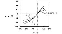
- 6 is a graph showing temperature dependence of current-voltage characteristics in the charge transfer resistance according to the first embodiment of the present invention.
- the block diagram which shows the 1st, 2nd learning process which concerns on 1st Embodiment of this invention.
- the time chart which shows transition of the direct current
- the time chart which shows transition of the voltage between terminals of the battery cell shown in FIG. 1, and electric current based on 1st Embodiment of this invention.
- the time chart which shows the effect of the 1st learning processing concerning a 1st embodiment of the present invention.
- the block diagram which shows the identification process of the charge transfer resistance parameter (beta) and the adaptation coefficients (gamma) v and (gamma) i based on 2nd Embodiment of this invention.
- formula and approximate expression of 0A vicinity based on 2nd Embodiment of this invention The time chart which shows transition of the voltage between terminals when the electric current which flows through the battery cell based on 2nd Embodiment of this invention changes suddenly.
- the flowchart which shows the procedure of the process of the selection part based on 2nd Embodiment of this invention.
- FIG. 1 shows a battery system 10 according to the first embodiment of the present invention.
- the battery system 10 includes a device that estimates parameters representing the state of a secondary battery, that is, an assembled battery (battery pack) 20.
- the battery system 10 can supply the electric power of the assembled battery 20 to an external device (for example, a vehicle including a rotating electrical machine as an in-vehicle main machine such as a motor generator).
- the battery system 10 can also be applied as a battery system in an in-vehicle system that utilizes an auxiliary battery such as an idling stop system.
- the battery system 10 includes the assembled battery 20 and a battery ECU (Electronic Control Unit) 30.
- the assembled battery 20 includes a series connection body of a plurality of battery cells 20a.
- the assembled battery 20 is connected to an electric load (not shown) including a generator such as a motor generator, and exchanges electric power with the electric load.
- an electric load including a generator such as a motor generator, and exchanges electric power with the electric load.
- secondary battery cells such as a lithium ion secondary battery cell, are used as each battery cell 20a.
- each battery cell 20a has a positive electrode, a negative electrode, an electrolyte, and a separator that separates the positive electrode and the negative electrode within the electrolyte. .
- An electric current can be supplied to the electric load connected to the assembled battery 20 by an electrochemical reaction in the electrolyte of each battery cell.
- the battery cell 20a configured as described above essentially has an internal impedance.
- This internal impedance includes, for example, direct current impedance, charge transfer impedance, and diffusion impedance.
- the DC impedance includes the resistance of each of the positive electrode and the negative electrode, and the resistance of the electrolyte in the battery cell 20a.
- the charge transfer impedance includes an RC parallel circuit composed of a pair of charge transfer resistors and electric double layer capacitors connected in parallel to each other.
- the charge transfer resistance and electric double layer capacity are, for example, reactions at the interface between ions in the electrolyte (lithium ions) and charges in the positive electrode, and between ions in the electrolyte and charges in the negative electrode. This is based on the reaction at the interface.
- the diffusion impedance includes an RC parallel circuit composed of a diffusion resistor and a diffusion capacitor connected in parallel with each other.
- the diffusion resistance and diffusion capacity are based on, for example, ion diffusion in the electrolyte and ion diffusion in the active material in each positive and negative electrode.
- the diffusion capacity represents that the diffusion resistance changes with time.
- the battery system 10 includes a plurality of voltage sensors 21, temperature sensors 22, and current sensors 23. These sensors are examples of sensors that can measure various physical characteristics of the battery pack 20.
- the voltage sensor 21 is a voltage detection unit that detects the inter-terminal voltage CCV of the corresponding battery cell 20a and outputs a detection signal representing the inter-terminal voltage CCV of the corresponding battery cell 20a to the battery ECU 30.
- the temperature sensor 22 detects the temperature Ts of the assembled battery 20, that is, the temperature Ts of each battery cell 20a, and sends a detection signal indicating the temperature Ts of the corresponding battery cell 20a (hereinafter referred to as cell temperature Ts) to the battery ECU 30. It is the temperature detection part which outputs.
- the current sensor 23 is a current detection unit that detects a current Is flowing through the assembled battery 20 (each battery cell 20a), that is, a charging current or a discharging current, and outputs a detection signal representing the detected current Is to the battery ECU 30.
- the polarity of the detection current Is becomes negative when the detection current Is is output from the assembled battery 20 and each battery cell 20a is discharged, and the detection current Is is input to the assembled battery 20 and the battery cell 20a. Becomes positive when is charged.
- the battery ECU 30 is configured as a well-known computer including a CPU 30a, a storage device, that is, a memory 31, an I / O (not shown), and other peripheral devices.
- the memory 31 stores information VTI related to various characteristic parameters of the assembled battery 20.
- CPU30a contains the some cell calculating part 32 corresponding to each of the some battery cell 20a. Detection signals from the voltage sensor 21, the temperature sensor 22, and the current sensor 23 are input to the battery ECU 30.
- each calculation unit 32 calculates the charging rate of the corresponding battery cell 20a, and the first and second learning processes that are characteristic configurations according to the first embodiment. And do.
- the charging rate calculation process, the first learning process, and the second learning process will be described in this order.
- Each calculation unit 32 includes an OCV conversion unit 33, a voltage deviation calculation unit 34, a current estimation unit 35, and an SOC calculation unit 36 as a state estimation unit 60 for performing the charging rate calculation process.
- the OCV conversion unit 33 calculates the open-circuit voltage OCV of the battery cell 20a based on the charging rate (State Of Charge, SOC) of the battery cell 20a in the previous calculation cycle calculated by the SOC calculation unit 36 described later.
- the OCV conversion unit 33 calculates the open end voltage OCV of each battery cell 20a using an OCV map in which the SOC and the open end voltage OCV are associated in advance.
- the OCV map is stored in the memory 31 as a part of the information VTI, for example.
- the voltage deviation calculation unit 34 outputs a value obtained by subtracting the open-end voltage OCV calculated by the OCV conversion unit 33 from the inter-terminal voltage CCV of the battery cell 20a detected by the voltage sensor 21.
- the current estimation unit 35 estimates the current flowing through the battery cell 20 a based on the output value of the voltage deviation calculation unit 34 and the temperature of the battery cell 20 a detected by the temperature sensor 22 (hereinafter, battery temperature Ts). Hereinafter, the current estimation method in the current estimation unit 35 will be described.
- the equivalent circuit model (battery model) 38 of the battery cell 20a that is, the internal impedance of the battery cell 20a, and the like used by the current estimation unit 35 to estimate the current flowing through the battery cell 20a is expressed using FIG.
- the battery model 38 that equivalently simulates the electrochemical behavior of the battery cell 20a will be described.
- the battery model 38 is basically expressed as a series connection body of a power source 38a, a DC resistance model 38b, a charge transfer impedance model 38c, and a diffusion impedance model 38d.
- the DC resistance model 38b has the above-described DC resistance Rs (resistance value Rs) in the battery cell 20a, and represents a potential difference (hereinafter referred to as DC resistance voltage) in the DC resistance Rs as Vs.
- the charge transfer impedance model 38c represents a charge transfer resistance (Rr indicating the above-described charge transfer impedance in the battery cell 20a, and a potential difference (hereinafter referred to as a charge transfer resistance voltage) in the charge transfer resistance Rr is expressed as Vbv. 3, the charge transfer impedance model shown in Fig. 3 is represented only by the charge transfer resistance Rr, which is a direct current resistance, and the electric double layer capacitance is ignored, which is the calculation unit 32 in the present embodiment. This is because one calculation cycle of the charging rate calculation process of the battery cell 20a in (CPU 30a) is set sufficiently longer than the time constant of the RC parallel circuit in the charge transfer impedance.
- the diffusion impedance model 38d has the above-described diffusion impedance in the battery cell 20a. That is, the diffusion impedance model 38d includes an RC parallel circuit composed of a diffusion resistance (resistance value Rw) and a diffusion capacitance (capacitance value Cw). The potential difference in the RC parallel circuit 38d is expressed as a polarization voltage Vw.
- the DC resistance model 38b will be described.
- the DC resistance voltage Vs of the DC resistance model 38b is expressed by the following equation (eq1).
- I represents the current flowing through the battery cell 20a.
- the direct current resistance Rs depends on the temperature of the battery cell 20a.
- an Rs map in which the DC resistance Rs and the battery temperature Ts are related in advance is stored in the memory 31 as a part of the information VTI, for example.
- the Rs map is adapted so that the higher the battery temperature Ts, the lower the DC resistance Rs.
- the current estimation unit 35 has a function of calculating the DC resistance Rs based on the battery temperature Ts and the Rs map.
- the Butler-Volmer formula for each battery cell 20a in electrochemistry is represented by the following formula (eq2).
- the above equation (eq9) “ ⁇ ” represents a charge transfer resistance parameter that is a parameter related to the charge transfer resistance Rr, “ ⁇ ” represents a physical constant, and “ ⁇ ” represents the fitness coefficient.
- the above equation (eq9) indicates that the charge / discharge current I flowing through the battery cell 20a and the charge transfer resistance voltage Vbv can be related by the charge transfer resistance parameter ⁇ .
- the detection current Is is the current I flowing through the battery cell 20a.
- the equation (eq9) is an inverse hyperbola in which the charge transfer resistance parameter ⁇ derived from the Butler-Volmer equation has the current I flowing through the battery cell 20a as an independent variable and the charge transfer resistance voltage Vbv as a dependent variable. In the sine function, this represents a coefficient that determines the relationship between the inverse hyperbolic sine function and the charge transfer resistance voltage Vbv.
- the exchange current density io follows the following equation (eq10) with respect to the absolute temperature T of the battery cell 20a.
- equation (eq10) “K t , ia” represents a constant.
- the temperature characteristic of the charge transfer resistance parameter ⁇ can be expressed by the following equation (eq11).
- Equation (eq12a) has the same form as the linear equation represented by the following equation (eq12b).
- A is K t and B is ln ( ⁇ 0).
- the memory 31 uses the linear function LF with respect to the absolute temperature T of the battery cell 20a at the natural logarithm ln ( ⁇ 0) of the charge transfer resistance parameter ⁇ , that is, the set of the y intercept ln ( ⁇ 0) and the slope K t as the information. It is stored as ⁇ map information which is a part of information of VTI. That is, the current estimation unit 35 refers to the ⁇ map based on the value of the absolute temperature T based on the battery temperature Ts detected by the temperature sensor 22, and the natural logarithm of the charge transfer resistance parameter ⁇ corresponding to the reciprocal of the absolute temperature T. The value of ln ( ⁇ 0) is extracted from the ⁇ map. Then, the current estimating unit 35 calculates the value of the charge transfer resistance parameter ⁇ by exponentially expanding the extracted natural logarithm ln ( ⁇ 0) of the charge transfer resistance parameter ⁇ .
- FIG. 5 shows the relationship between the current I and the charge transfer resistance voltage Vbv based on the above equation (eq5), at different temperatures of the battery cell 20a (25 ° C., 10 ° C., 0 ° C., ⁇ 10 ° C., and ⁇ 20 ° C. ) As parameters, respectively.
- the charge transfer resistance voltage Vbv calculated by the above equation (eq5) is when the battery temperature Ts of the battery cell 20a is within a low temperature range, for example, a temperature range of 0 ° C. or less. It changes non-linearly with changes in the current I.
- the charge transfer resistance voltage Vbv using the above equation (eq5), in other words, the charge transfer resistance parameter ⁇ , the actual current I and the charge transfer resistance of the battery cell 20a in a low temperature region of, for example, 0 ° C. or less.
- the charge transfer resistance voltage Vbv having a non-linear current-voltage characteristic that matches the non-linear characteristic between the voltage Vbv and the voltage Vbv can be calculated.
- the diffusion impedance model 38d will be described.
- the polarization voltage Vw of the diffusion impedance model 38d is expressed by the following equation (eq13).
- A is represented by the following equation (eq13A)
- B is represented by the following equation (eq13B).
- the above equation (eq13) is an equation obtained by discretizing the transfer function of the RC parallel circuit 38d by bilinear transformation, and “ ⁇ T” indicates one calculation cycle of the calculation unit 32. Further, (t) given to the polarization voltage Vw and the parameter B ⁇ Is in the above equation (eq13) indicates that the polarization voltage Vw and the parameter B ⁇ Is are values in the current calculation cycle in the calculation unit 32. Show. Further, (t ⁇ 1) added to the parameter ( ⁇ A ⁇ Vw) and the parameter B ⁇ Is in the above equation (eq13) is the value in the previous calculation cycle in the calculation unit 32. It is shown that.
- information regarding each of the resistance value Rw of the resistance component term and the capacitance Cw of the capacitance component term of the RC parallel circuit 38d is the battery temperature Ts detected by the temperature sensor 22. And is stored in the memory 31 as part of the information VTI. Information relating to each of the resistance value Rw of the resistance component term and the capacitance Cw of the capacitance component term is related to the absolute temperature T based on the battery temperature Ts detected by the temperature sensor 22 as diffusion impedance information. This is because each of the resistance value Rw and the capacitance Cw depends on the battery temperature T.
- the current estimation unit 35 determines the resistance value Rw and the capacitance component term of the resistance component term in the diffusion impedance. Has a function of calculating the electrostatic capacitance Cw.
- the output value of the voltage deviation calculation unit 34 is an added value of the DC resistance voltage Vs, the charge transfer resistance voltage Vbv, and the polarization voltage Vw described above.
- the process performed by the current estimation unit 35 is a process of calculating the current that generates the added value “Vs + Vbv + Vw” as the estimated current Ie.
- the current estimation unit 35 first determines the DC resistance Rs, the charge transfer resistance parameter ⁇ , the resistance value Rw of the resistance component term of the RC parallel circuit 38d, and the capacitance Cw of the capacitance component term based on the battery temperature T. Calculate each. Then, the current estimation unit 35 sets, as the estimated current Ie, a current such that the added value on the right side of each of the equations (eq1), (eq9), and (eq13) matches the output value of the voltage deviation calculation unit 34. calculate. In this calculation process, the estimated current Ie calculated in the previous calculation cycle may be used as Is (t ⁇ 1) on the right side of the above equation (eq13).
- the SOC calculation unit 36 calculates the SOC of the battery cell 20a based on the estimated current Ie calculated by the current estimation unit 35.
- the SOC calculation unit 36 may calculate the SOC by, for example, the following equation (eq14).
- the SOC calculation unit 36 may calculate the initial SOC0 as follows, for example. Specifically, the SOC calculation unit 36 detects the voltage between the terminals of the battery cell 20a as the open-circuit voltage OCV by the voltage sensor 21 on the condition that charging / discharging of the assembled battery 20 is stopped. Then, the SOC calculation unit 36 receives the detected open-end voltage OCV as an input, and calculates the initial SOC0 using the OCV map.
- First learning process The 1st learning process about the battery cell 20a which corresponds in each calculating part 32 is demonstrated using FIG.
- This first learning process addresses the possibility that the charge transfer resistance parameter ⁇ may deviate from an appropriate value (for example, a value assumed at the time of design) due to deterioration of the battery cell 20a or the like. That is, the first learning process is a process for learning the charge transfer resistance parameter ⁇ used in the current estimation unit 35. Thereby, even if deterioration or the like occurs in the battery cell 20a, it is possible to avoid a decrease in SOC estimation accuracy due to the processing shown in FIG.
- Each calculation unit 32 includes a Vs calculation unit 40, a Vbv calculation unit 41, and a first learning unit 42 as processing units for performing the first learning process.
- the Vs calculating unit 40 is based on the DC resistance Rs calculated from the battery temperature Ts and the current detected by the current sensor 23 (hereinafter, detected current Is), and the DC resistance voltage represented by the above equation (eq1). Vs is calculated.
- the Vbv calculation unit 41 is based on the charge transfer resistance parameter ⁇ calculated from the battery temperature Ts, the detection current Is, and the correction coefficient ⁇ k calculated in the previous calculation cycle, and the charge transfer represented by the above equation (eq9).
- the resistance voltage Vbv is calculated.
- the correction coefficient ⁇ k is a parameter learned by the first learning unit 42 in order to correct the charge transfer resistance parameter ⁇ deviated from an appropriate value due to deterioration of the corresponding battery cell 20a or the like. eq15).
- ln ( ⁇ k) represents the amount of change in the Y intercept of the Arrhenius plot in FIG.
- the first learning unit 42 corrects the correction coefficient ⁇ k based on the DC resistance voltage Vs calculated by the Vs calculation unit 40, the charge transfer resistance voltage Vbv calculated by the Vbv calculation unit 41, the detection current Is, and the inter-terminal voltage CCV. To learn.
- the first learning unit 42 includes a “first deviation calculation unit 42a”, a “second deviation calculation unit 42b”, and a “first parameter estimation unit 42c”.
- a learning method (learning process) by the first learning unit 42 will be described.
- the 1st learning part 42 may be implement
- the left side of the above equation (eq17) shows the detection current deviation ⁇ Is (t) (“first”) which is the difference between the detection current Is (t) in the current calculation cycle and the detection current Is (t ⁇ 1) in the previous calculation cycle. 1 deviation ”).
- the right side of the above equation (eq17) indicates the estimated current deviation ⁇ F (t) (corresponding to “second deviation”).
- the charge transfer resistance voltage Vbv (t) of the current calculation cycle (t) shown on the right side of the above equation (eq17) is represented by the following equation (eq18).
- CCV (t) is the inter-terminal voltage CCV in the current calculation cycle (t)
- Vs (t) is the DC resistance voltage Vs in the current calculation cycle (t)
- Vw (t) is the current calculation cycle.
- the polarization voltage Vw and OCV (t) at (t) indicate the open-circuit voltage OCV at the current calculation cycle (t), respectively.
- the influence of the polarization voltage Vw and the open-circuit voltage OCV can be reduced to significantly measure the influence of the charge transfer resistance voltage Vbv when the absolute value of the detected current deviation ⁇ Is is large during vehicle acceleration or the like. This is because each of the DC resistance voltage Vs and the charge transfer resistance voltage Vbv changes to a value corresponding to the detected current deviation ⁇ Is, while the amount of change for one calculation period of the polarization voltage Vw has a time constant. This is because it is very small and can be ignored.
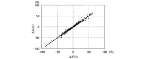
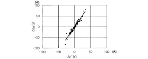
- FIG. 8 when the battery cell 20a is not deteriorated and the initial value of the charge transfer resistance parameter ⁇ is an appropriate value, the detection current Is and the terminal at a low temperature (for example, ⁇ 15 ° C.) The measurement result of inter-voltage CCV is shown.
- FIG. 9 is a diagram in which the estimated current deviation ⁇ F and the detected current deviation ⁇ Is calculated based on this measurement result are plotted.
- the estimated current deviation ⁇ F is a value obtained by calculating the right side of the above equation (eq17) using the charge transfer resistance voltage Vbv calculated based on the above equation (eq18).
- the first learning unit 42 learns a correction coefficient ⁇ k for making the estimated current deviation ⁇ F coincide with the detected current deviation ⁇ Is.
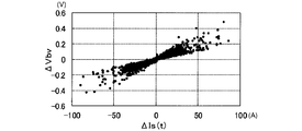
- the detected current deviation ⁇ Is is plotted on the horizontal axis without using the above equation (eq17), and the charge transfer resistance voltage Vbv in one calculation cycle using the above equation (eq18).
- FIG. 11 shows the change ⁇ Vbv plotted on the vertical axis.
- the non-linearity of the current-voltage characteristics of the battery cell 20a becomes strong at low temperatures.
- the linearity of the variation ⁇ Vbv of the charge transfer resistance voltage Vbv with respect to the detected current deviation ⁇ Is is not ensured.
- each parameter is expressed as the following equation (eq19).
- the 1st learning part 42 can calculate 1st parameter estimated value (theta) 1 (t) for every calculation period based on the following Formula (eq20) derived
- the first learning unit 42 calculates the first parameter estimated value ⁇ 1 (t) as the reciprocal “1 / ⁇ k (t)” of the correction coefficient ⁇ k (t). Then, the calculation unit 32 including the Vbv calculation unit 41 calculates the correction coefficient ⁇ k, that is, the correction coefficient calculated based on the correction coefficient ⁇ k, that is, the first parameter estimated value ⁇ 1 (t), on the charge transfer resistance parameter ⁇ of the ⁇ map corresponding to the battery temperature Ts. The charge transfer resistance parameter ⁇ is updated by multiplying ⁇ k (t). Thereby, the updated charge transfer resistance parameter ⁇ is used in the Vbv calculation unit 41 and the current estimation unit 35.
- the calculation unit 32 includes a “first update unit (update unit) 32 a” that performs the update process of the charge transfer resistance parameter ⁇ .
- the calculation unit 32 functions as a “first update unit (update unit) 32a” that performs the update process of the charge transfer resistance parameter ⁇ .
- FIG. 12 shows transitions of the true value and the estimated value of the inter-terminal voltage CCV of the battery cell 20a at a low temperature (for example, ⁇ 15 ° C.).
- the estimated value is the open-circuit voltage OCV calculated by the OCV conversion unit 33, the DC resistance voltage Vs calculated by the Vs calculation unit 40, the charge transfer resistance voltage Vbv calculated by the Vbv calculation unit 41, and This corresponds to the added value of the polarization voltage Vw calculated based on the above equation (eq13).
- the initial value of the charge transfer resistance parameter ⁇ is deviated from an appropriate value representing the charge transfer impedance model. For this reason, the estimated value of the inter-terminal voltage CCV greatly deviates from the true value during a certain period after the first learning process is started. However, thereafter, the charge transfer resistance parameter ⁇ is sequentially updated by the first learning process, so that the estimated value of the inter-terminal voltage CCV matches the true value.
- Second learning process The 2nd learning process about the battery cell 20a corresponding in each calculating part 32 is demonstrated using FIG.
- This second learning process is a process for learning the resistance value Rw of the resistance component term and the capacitance Cw of the capacitance component term in the diffusion impedance model 38d.
- Each computing unit 32 includes a second learning unit 43 in addition to the Vs calculation unit 40 and the Vbv calculation unit 41 as a processing unit for performing the second learning process, as shown in FIG.
- the second learning unit 43 learns the resistance value Rw of the resistance component term and the capacitance Cw of the capacitance component term based on the DC resistance voltage Vs, the charge transfer resistance voltage Vbv, the detection current Is, and the inter-terminal voltage CCV.
- the second learning unit 43 includes a “second parameter estimation unit 43a”.
- a learning method (learning process) by the second learning unit 43 will be described.
- FIG. 13 shows a circuit model LM used in the second learning unit 43 to learn the resistance value Rw of the resistance component term and the capacitance Cw of the capacitance component term according to this embodiment.
- This circuit model LM includes an error resistor directly connected to a parallel connection body of a resistance component term Rw and a capacitance component term Cw.
- the resistance value of the error resistor is indicated by “R E ”.
- the error resistor is provided in view of the fact that each of the charge transfer resistance voltage Vbv and the DC resistance voltage Vs can include an error.
- a change amount (hereinafter, voltage change amount ⁇ Vin) in one calculation cycle of the applied voltage Vin is expressed by the following equation (eq22).
- each parameter is expressed as the following equation (eq24).
- the second learning unit 43 can calculate the second parameter estimated value ⁇ 2 (t) based on the following equation (eq25) derived from the sequential least square method.
- the second learning unit 43 calculates the resistance value Rw of the resistance component term, the capacitance Cw of the capacitance component term, and the resistance of the error resistance based on the calculated second parameter estimated value ⁇ 2 (t) and the following equation (eq26).
- the value R E is calculated.
- the calculation unit 32 calculates diffusion impedance information regarding the resistance value Rw of the resistance component term and the capacitance Cw of the capacitance component term stored in the memory 31 in a state associated with the battery temperature Ts (absolute temperature T). Updating is performed based on the resistance value Rw and the capacitance Cw calculated, that is, learned by the second learning unit 43. The updated information is used in the current estimation unit 35. That is, in the present embodiment, the calculation unit 32 includes a “second update unit 32b” that performs the update process of the diffusion impedance information.
- the calculation unit 32 functions as a “second update unit 32b” that performs the update process of the diffusion impedance information.
- the second learning unit 43 appropriately applies a low-pass filter (LPF) that matches the time constant of the RC parallel circuit to be learned to all of the parameters Vs, Vbv, Is, and CCV input to the second learning unit 43. May be applied. Thereby, the learned resistance value Rw and capacitance Cw can be set to stable values.
- LPF low-pass filter
- SOC calculation unit 36 for example of the arithmetic unit 32, the terminal voltage CCV of the battery cell 20a detected by the voltage sensor 21, the resistance value R multiplied values of E and the detection current Is of the error resistance, DC resistance voltage Vs,
- the open end voltage OCV may be calculated by subtracting the added value of the charge transfer resistance voltage Vbv and the polarization voltage Vw. Then, the SOC calculation unit 36 may calculate the SOC of the battery cell 20a based on the calculated open-end voltage OCV and the OCV map.
- the battery ECU 30 uses a charge transfer impedance model that includes a charge transfer resistance parameter ⁇ that correlates with the battery temperature Ts (or absolute temperature T), which is a parameter corresponding to a Butler-Volmer exchange current density. For this reason, the current-voltage nonlinear characteristic of each battery cell 20a can be accurately represented even at low temperatures. Then, the battery ECU 30 sequentially updates the charge transfer resistance parameter ⁇ by the first learning process using the sequential least square method. For this reason, even if each battery cell 20a deteriorates or the initial value of the charge transfer resistance parameter ⁇ deviates from an appropriate value, it is possible to avoid a decrease in the estimation accuracy of the SOC of the battery cell 20a. it can.
- the battery ECU 30 performs the first learning process when the absolute value of the detected current deviation ⁇ Is is equal to or greater than the predetermined value Ith. For this reason, it is possible to determine when the charge transfer resistance whose nonlinear behavior is dominant in the behavior of the voltage fluctuation of the battery cell 20a, and at this determination, it is possible to calculate the correction coefficient ⁇ k for correcting the charge transfer resistance parameter ⁇ . . As a result, erroneous learning of the correction coefficient K due to the influence of the polarization voltage Vw can be avoided.
- the battery ECU 30 obtains the resistance value Rw of the resistance component term and the capacitance Cw of the capacitance component term in the RC parallel equivalent circuit model 38d by the second learning process using the error resistance connected in series to the RC parallel equivalent circuit model 38d. Updated sequentially. For this reason, it is possible to suppress the influence of errors included in the DC resistance voltage Vs and the charge transfer resistance voltage Vbv on the calculation of the polarization voltage Vw. On the other hand, when no error resistor is provided, the estimated resistance value Rw of the resistance component term includes the influence of the error, and there is a concern that the estimation accuracy of the resistance value Rw may be reduced.
- each calculation unit 32 sequentially identifies the fitness coefficient ⁇ in addition to the charge transfer resistance parameter ⁇ by an adaptive digital filter. Update. This is in view of the possibility that the adaptation coefficient ⁇ may deviate from an appropriate value (for example, a value adapted at the time of design) due to deterioration or the like of the battery cell 20a.
- FIG. 14 shows a processing unit 61 provided in each calculation unit 32 for identifying the charge transfer resistance parameter ⁇ and the fitness coefficient ⁇ .
- the processing unit 61 has a configuration corresponding to the first learning unit 42 described in the first embodiment. That is, the charge transfer resistance parameter ⁇ and the fitness coefficient ⁇ identified by the processing unit 61 are used for calculation of the estimated current Ie in the current estimation unit 35 constituting the state estimation unit 60. Specifically, the current estimation unit 35 updates the parameters ⁇ and ⁇ included in the right side of the above equation (eq9) used for calculating the estimated current Ie with the input parameters ⁇ and ⁇ .
- the processing unit 61 includes a parameter identification unit 50.
- the parameter identification unit 50 includes a first identification unit 51 that identifies the charge transfer resistance parameter ⁇ and a second identification unit 52 that identifies the fitness coefficient ⁇ .
- initial parameter ⁇ map The initial value of the charge transfer resistance parameter (hereinafter referred to as “initial parameter ⁇ map”) is expressed by the following equation (eq27).
- the initial parameter ⁇ map is formulated into a form in which the natural logarithm of the initial parameter ⁇ map is a linear expression with respect to the reciprocal of the battery temperature Ts. It is stored in the memory 31 as part of the VTI. For this reason, if the battery temperature Ts can be grasped, the initial parameter ⁇ map can be determined. Thereby, when the battery ECU 30 is activated, the initial value of the charge transfer resistance parameter ⁇ , that is, the initial parameter ⁇ map can be set accurately.
- the charge transfer resistance parameter ⁇ is defined as in the following equation (eq29).
- each calculation unit 32 receives the battery temperature Ts as an input and calculates a natural logarithm value corresponding to the battery temperature Ts based on the mathematical formula stored in the memory 31 in the form of the above equation (eq28). .
- This calculation function is provided, for example, in the current estimation unit 35 shown in FIG. That is, the current estimation unit 35 functions as a calculation unit.
- the current estimation unit 35 obtains an initial parameter ⁇ map by converting the calculated natural logarithm value ln ( ⁇ map) into an exponential function, and multiplies the initial parameter ⁇ map by a correction coefficient ⁇ k as shown in the above equation (eq29).
- a charge transfer resistance parameter ⁇ is calculated.
- the charge transfer resistance parameter ⁇ is a parameter that changes exponentially with respect to the temperature of the battery cell 20a as shown in the above equation (eq28). As shown in FIG. 4, the digit can be changed so as to change greatly. For this reason, when using an adaptive digital filter, it is desirable not to directly identify the charge transfer resistance parameter ⁇ but to identify the correction coefficient ⁇ k, which is a value obtained by standardizing the charge transfer resistance parameter ⁇ . This is to avoid a reduction in the identification accuracy of the charge transfer resistance parameter ⁇ caused by the minimum operation unit (Least Significant Bit: LSB) in each operation unit 32.
- LSB Minimum Opera unit
- the charge transfer resistance parameter ⁇ is directly identified. Since the charge transfer resistance parameter ⁇ varies greatly depending on the operating temperature of the battery cell 20a, the charge transfer resistance parameter ⁇ varies depending on the temperature during the travel of the vehicle or the time when the charge transfer resistance parameter ⁇ converges depending on the season. There is a concern that the identification accuracy of ⁇ is lowered. On the other hand, since the correction coefficient ⁇ k is normalized, it is possible to calculate a stable correction coefficient ⁇ k. Further, by normalizing the correction coefficient ⁇ k, it is possible to avoid concerns such as a loss of digits, so that it is possible to avoid a decrease in the identification accuracy of the charge transfer resistance parameter ⁇ .
- the initial parameter ⁇ map is stored in the memory 31 in the form expressed by the above equation (eq28). For this reason, the change width of ln ( ⁇ map) in the operating temperature range of the battery cell 20a can be reduced. Thereby, the accuracy of the initial parameter ⁇ map can be increased.
- the initial parameter ⁇ map stored in the memory 31 may deviate from the design-use conformity indicated by the solid line, as indicated by the one-dot chain line in FIG.
- This deviation can be corrected by the correction coefficient ⁇ k.
- the Y-intercept of the Arrhenius plot changes due to deterioration or the like.
- this change is corrected by the correction coefficient ⁇ k.
- K t denotes a constant determined from the physical constants. For this reason, the inclinations of the solid line and the alternate long and short dash line in FIG. 15 do not change before and after the deterioration of the battery cell 20a or the like.
- the above equation (eq32) is an equation that can be approximated around 0 A of the current I flowing through the battery cell 20a, and is a linear equation of the charge transfer resistance voltage Vbv with respect to the current I.
- “ ⁇ ⁇ T ⁇ ⁇ map ⁇ ⁇ k” has a dimension of resistance
- ⁇ is a physical constant
- the difference between the inter-terminal voltage CCV (t) detected by the voltage sensor 21 in the current calculation cycle and the inter-terminal voltage CCV (t ⁇ 1) in the previous calculation cycle is defined as a detected voltage deviation ⁇ V (t).
- the detected voltage deviation ⁇ V (t) is expressed by the following equation (eq33) with reference to the above equation (eq18).
- Each calculation unit 32 sequentially identifies the correction coefficient ⁇ k using the detected voltage deviation ⁇ V (t) and the detected current deviation ⁇ I (t) when the detected current Is greatly changes.
- FIG. 17 (a) the transition of the voltage between the terminals of the battery cell 20a is shown in FIG. 17 (a), and the transition of the current I flowing in the battery cell 20a is shown in the reference (b) of FIG.
- a constant load is applied to the battery cell 20a after the time t1 in the no-load state.
- the voltage drop amount ⁇ Vw having a large time constant is sufficiently smaller than the voltage drop amount “ ⁇ Vs + ⁇ Vbv” having no time constant.
- the change amount ⁇ OCV of the open-circuit voltage OCV is also sufficiently smaller than the voltage drop amount “ ⁇ Vs + ⁇ Vbv”. For this reason, each change amount ⁇ OCV (t), ⁇ Vw (t) in one sufficiently short calculation period can be ignored. Therefore, the above equation (eq30) can be expressed as the following equation (eq34).
- each calculation unit 32 can extract the DC resistance voltage Vs and the charge transfer resistance voltage Vbv from the detected voltage deviation ⁇ V. Further, by ignoring each change amount ⁇ OCV (t), ⁇ Vw (t), the calculation load in each calculation unit 32 can be reduced.
- each parameter is represented as the following equation (eq36).
- ya represents an observed value.
- the model estimated value yaest and the estimation error ⁇ a are expressed by the following equation (eq37).
- Each calculation unit 32 sequentially identifies the parameter estimation value ⁇ a by the sequential least square method based on the following equation (eq38) so as to minimize the estimation error ⁇ a.
- the parameter identification unit 50 receives the observed value ya (t) determined by the detected voltage deviation ⁇ V (t), the detected current deviation ⁇ I (t), and the DC resistance Rs as input, and sequentially minimizes it based on the above equations (eq37) and (eq38).
- the parameter estimation value ⁇ a is sequentially identified by the square method, and the correction coefficient ⁇ k is calculated from the identified parameter estimation value ⁇ a.
- the first identifying unit 51 uses the observation value ya (t) based on the DC resistance Rs calculated from the detected voltage deviation ⁇ V (t), the detected current deviation ⁇ I (t), and the battery temperature Ts. Is calculated.
- the first identification unit 51 receives the observed value ya as input, sequentially identifies the parameter estimated value ⁇ a by the sequential least square method based on the above equations (eq37) and (eq38), and corrects the correction coefficient ⁇ k from the identified parameter estimated value ⁇ a. Is calculated.
- the processing unit 61 includes a current change amount calculation unit 53, a voltage change amount calculation unit 54, and a selection unit 55 in addition to the parameter identification unit 50.
- the detected current deviation ⁇ I (t) is calculated by the current change amount calculation unit 53, and the detected voltage deviation ⁇ V (t) is calculated by the voltage change amount calculation unit 54.
- the DC resistance Rs is calculated based on the Rs map described above.
- the adaptation coefficient ⁇ is a proportionality coefficient that defines the relationship between the charge transfer resistance voltage Vbv and the current I flowing through the battery cell 20a.
- the fitness coefficient ⁇ c when the battery cell 20a is charged may be set separately from the fitness coefficient ⁇ d when the battery cell 20a is discharged.
- the charge-side fitness coefficient ⁇ c is set to 0.25, for example, and the discharge-side fitness coefficient ⁇ d is set to 0.14, for example.
- the processing unit 61 calculates the difference between the detected voltage deviation ⁇ V (t) and the detected current deviation ⁇ I (t) when the current I changes greatly from time t ⁇ 1 to time t.
- the fitness coefficient ⁇ is sequentially identified from the relationship.
- ⁇ v represents a first coefficient that is a fitting coefficient that defines expansion or contraction in the direction of the charge transfer resistance voltage Vbv in the Butler-Volmer equation
- ⁇ i represents the battery cell 20a in the Butler-Volmer equation.
- regulates the expansion or contraction in the direction of the flowing electric current I is shown.
- the processing unit 61 identifies the first coefficient ⁇ v at time t, and applies the first coefficient ⁇ v identified after one calculation cycle to the second coefficient ⁇ i.
- each parameter is expressed as the following equation (eq40).
- yb represents an observed value.
- the model estimated value ybest and the estimation error ⁇ b are expressed by the following equation (eq41).
- the processing unit 61 sequentially identifies the parameter estimated value ⁇ b by the sequential least square method based on the following equation (eq42) so as to minimize the estimation error ⁇ b. Then, the processing unit 61 calculates the first coefficient ⁇ v by taking the reciprocal of the parameter estimated value ⁇ b.
- the second identification unit 52 of the processing unit 61 calculates the observed value yb (t) based on the detected voltage deviation ⁇ V (t), the detected current deviation ⁇ I (t), and the DC resistance Rs.
- the second identification unit 52 receives the observed value yb as input, and sequentially identifies the parameter estimated value ⁇ b by the successive least square method based on the above equations (eq41) and (eq42).
- the second identification unit 52 calculates the first coefficient ⁇ v by taking the reciprocal of the parameter estimated value ⁇ b.
- the second identification unit 52 applies the identified first coefficient ⁇ v to the second coefficient ⁇ i.
- the identification of the correction coefficient ⁇ k in the first identification unit 51 is performed when the current I flowing through the battery cell 20a is small (for example, smaller than a predetermined value).
- the identification of the first and second coefficients ⁇ v and ⁇ i in the second identification unit 52 is performed when the current I flowing through the battery cell 20a is large (for example, larger than the predetermined value). Therefore, in the present embodiment, the calculation unit 32 includes a selection unit 55 that selects which of the charge transfer resistance parameter ⁇ and the adaptation coefficient ⁇ is identified in the current calculation cycle.
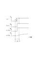
- the selection process executed by the processing unit 61 including the selection unit 55 will be described with reference to FIG. This process is repeatedly executed by the processing unit 61 at a predetermined calculation cycle, for example.
- step S10 the selection unit 55 determines whether or not the absolute value of the detected current deviation ⁇ I (t) is equal to or greater than a specified value Id.
- This process is a process for determining whether or not each of the changes ⁇ OCV and ⁇ Vw is in a state that can be ignored, as indicated by the above equation (eq34).
- step S10 the selection process proceeds to step S11.
- step S11 the selection unit 55 sets the first condition that the absolute value of the detection current Is (t) in the current calculation cycle is less than the threshold Ir, and the detection current Is (t-1) in the previous calculation cycle. It is determined whether the logical product of the second condition that the absolute value of is less than the threshold value Ir is true, that is, whether both the first condition and the second condition are satisfied.
- the threshold Ir is 1 ⁇ 2 of the current range SI that can approximate the Butler-Volmer equation represented by the above equation (eq9) with the approximate equation of the above equation (eq31). This value is set larger as the battery temperature Ts is higher.
- the higher the battery temperature Ts the larger the threshold Ir is set because the slope when the current I flowing through the battery cell 20a is in the vicinity of 0 A in the Butler-Volmer equation shown in FIG. 5 is the battery cell 20a. This is because the temperature becomes smaller and the shape becomes more linear.
- step S11 the selection process proceeds to step S12.
- step S12 the first identification unit 51 identifies the correction coefficient ⁇ k.
- step S13 the selection process proceeds to step S13, and the second identification unit 52 identifies the first coefficient ⁇ v and the second coefficient ⁇ i.
- the correction coefficient ⁇ k, the first coefficient ⁇ v, and the second coefficient ⁇ i identified by the parameter identification unit 50 are input to the current estimation unit 35.
- the charge transfer resistance parameter ⁇ is updated based on the correction coefficient ⁇ k.
- the current estimation unit 35 calculates the estimated current Ie based on the updated charge transfer resistance parameter ⁇ , the first coefficient ⁇ v, and the second coefficient ⁇ i.
- the inter-terminal voltage CCV the inter-terminal voltage estimated value Ve
- the estimated value Ve is the open-circuit voltage OCV calculated by the OCV conversion unit 33, the DC resistance voltage Vs calculated by the Vs calculation unit 40, and the charge transfer calculated using the updated charge transfer resistance parameter ⁇ .
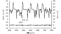
- the predetermined traveling mode in FIG. 20 is the LA # 4 mode (one of traveling patterns for exhaust gas measurement).
- the inter-terminal voltage CCV, the inter-terminal voltage estimated value Ve, and the estimated value Ve and the inter-terminal voltage CCV at a low temperature (for example, ⁇ 20 ° C.) where the error ⁇ Vrr is likely to be large.
- the transition of the error ⁇ Vrr is shown. Even at low temperatures, the error ⁇ Vrr is maintained in a very small state. For this reason, in FIG. 20, the transition of the inter-terminal voltage CCV and the transition of the estimated value Ve are almost overlapped.
- FIG. 21 shows a correlation diagram between the detected current Is, the estimated value of the inter-terminal voltage CCV (indicated by Ve), and the detected value of the inter-terminal voltage CCV (indicated by CCV) in the data period shown in FIG.
- the nonlinear characteristic between the detected current Is and the estimated value Ve of the inter-terminal voltage CCV can be expressed with high accuracy, and the inter-terminal voltage CCV of the battery cell 20a can be estimated with high accuracy. it can.
- the charge transfer impedance model can be appropriately updated. Thereby, the calculation accuracy of the estimated voltage Ve of the inter-terminal voltage CCV can be increased.
- the charge transfer resistance parameter ⁇ may be directly identified without using the correction coefficient ⁇ k based on the following equation (eq44) instead of the above equation (eq17).
- the diffusion resistance model is not limited to an RC equivalent circuit model including one parallel connection body of a resistor and a capacitor, but may be an RC equivalent circuit model in which a plurality of the parallel connection bodies are connected in series.
- the SOC is estimated as the state of the battery cell 20a, but is not limited thereto.
- the maximum power that can be discharged from the battery cell 20a over a specified time may be estimated, or the deterioration state of the battery cell 20a may be estimated.
- the second learning process is not essential.
- the initial parameter ⁇ map may be stored in the memory 31 as a part of the information VTI, for example, according to the above equation (eq27).
- the natural logarithm of the initial parameter ⁇ map is formulated into a linear expression with respect to the reciprocal of the battery temperature Ts and stored in the memory 31 as a part of the information VTI, for example, but is not limited thereto.
- the natural logarithm of the initial parameter ⁇ map may be mapped in the form of a linear expression with respect to the reciprocal of the battery temperature Ts and stored in the memory 31 as a part of the information VTI, for example.
- each calculation unit 32 selects a natural logarithm value corresponding to the battery temperature Ts from the stored natural logarithm values of the initial parameter ⁇ map.
- the battery temperature Ts is measured at least three points, and based on the measured values of at least three battery temperatures Ts.
- the map can be created. For this reason, the adaptation operation
- the threshold Ir may be set to a different value depending on whether the battery cell 20a is charged or discharged if the linearity in the vicinity of 0A is maintained. Further, in the case where the discharge current and the charge current are different depending on how the battery cell 20a is used, the first embodiment and the second embodiment are also established even in a region where the linearity near 0A is not maintained. A mode in which the two identification units 52 are combined may be employed. Furthermore, since the fitness coefficient ⁇ c when the battery cell 20a is generally charged and the fitness coefficient ⁇ d when the battery cell 20a is discharged are often different, ⁇ c and ⁇ d are different during charging and discharging, respectively. It is effective to improve the accuracy by separating and identifying.
- an opportunity to identify the first and second coefficients ⁇ v and ⁇ i may be secured even when an affirmative determination is made in step S11 in FIG.
- the resistance value Rw of the resistance component term and the capacitance Cw of the capacitance component term used in the current estimation unit 35 are learned by the second learning unit 43 described in FIG. 6 of the first embodiment. May be.
- the battery cell 20a is not limited to a lithium ion secondary battery, but may be another secondary battery such as a nickel metal hydride battery.
- the battery temperature used for each process is not limited to the detection value of the temperature sensor 22, but may be a battery temperature estimated by h using any of various known battery temperature estimation methods. Good.
- the application target of the present invention is not limited to vehicles.
Landscapes
- Engineering & Computer Science (AREA)
- Manufacturing & Machinery (AREA)
- Chemical & Material Sciences (AREA)
- Chemical Kinetics & Catalysis (AREA)
- Electrochemistry (AREA)
- General Chemical & Material Sciences (AREA)
- Physics & Mathematics (AREA)
- General Physics & Mathematics (AREA)
- Power Engineering (AREA)
- Secondary Cells (AREA)
Abstract
電池状態推定装置は、更新部を有している。この更新部は、直流抵抗モデル、電荷移動インピーダンスモデル、および拡散インピーダンスモデルの直列接続体により構成された2次電池の電池モデルにおける前記電荷移動インピーダンスモデルを、前記2次電池に流れる電流検出値の変化量に基づいて、バトラーボルマー式によって規定される前記2次電池に流れる電流及び前記電荷移動抵抗の電位差間の第1の関係を、前記2次電池に実際に流れる電流値及び前記電荷移動抵抗の実際の電位差の値の間の第2の関係に近づけるように、更新する。状態推定部は、更新部によって更新された前記電荷移動インピーダンスモデルを含む前記電池モデルに基づいて、前記2次電池の状態を推定する。
Description
本発明は、2次電池の電池モデルに基づいて、前記2次電池の状態を推定する装置に関する。
2次電池の状態を推定する装置としては、下記特許文献1に開示された装置がある。この特許文献1に開示された装置は、1つの抵抗および1つのRC並列回路が直列接続された等価回路として表現された2次電池の電池モデルを表すパラメータの値を、適応デジタルフィルタを用いて一括推定する。そして、この装置は、推定した各パラメータの値に基づいて、2次電池の充電率を推定する。
一般的な2次電池は、その低温領域において、非線形な電流-電圧特性を有している。残念ながら、上記特許文献1に記載された電池モデルの構成は、RC並列回路の時定数が小さいため、2次電池の電流-電圧特性が非線形に変化する場合において、該電流-電圧特性を表すことは困難である。特に、0℃以下の低温領域では、非線形変化の度合いが無視できないほど大きくなる。このため、上記特許文献1に記載された電池モデルでは、2次電池の低温領域において、2次電池の状態の推定精度が低下するおそれがある。
本発明は、2次電池の低温時においても、2次電池の状態の推定精度の低下を回避できる電池状態推定装置を提供することを主たる狙いとする。
本発明における例示態様に関わる電池状態推定装置は、2次電池(20a)の直流抵抗(Rs)を表す直流抵抗モデル、前記2次電池の電荷移動インピーダンスを表すモデルであって、バトラーボルマー式から導かれ、交換電流密度と相関のある電荷移動抵抗パラメータ(β)を含む電荷移動インピーダンスモデル、および抵抗とキャパシタとの並列接続体を含むRC等価回路モデルであって、前記2次電池の拡散インピーダンスを表す拡散インピーダンスモデル、の直列接続体により構成された当該2次電池の電池モデルにおける前記電荷移動インピーダンスモデルを、前記2次電池に流れる電流検出値の変化量に基づいて、前記バトラーボルマー式によって規定される前記2次電池に流れる電流及び前記電荷移動抵抗の電位差間の第1の関係を、前記2次電池に実際に流れる電流値及び前記電荷移動抵抗の実際の電位差の値の間の第2の関係に近づけるように、更新する処理を行う更新部(30)を備えている。また、電池状態推定装置は、前記更新部によって更新された前記電荷移動インピーダンスモデルを含む前記電池モデルに基づいて、前記2次電池の状態を推定する状態推定部(30)を備えている。
2次電池の内部インピーダンスは、直流抵抗、電荷移動インピーダンス、及び拡散インピーダンスに大きく分けられる。このため、上記発明の例示態様では、電池モデルを、直流抵抗モデル、電荷移動インピーダンスモデル、及び拡散インピーダンスモデルの直列接続体を含むモデルとしている。
ここで、2次電池の低温時には、電荷移動インピーダンスに起因する電流-電圧の非線形特性が支配的となる。このため、上記発明の例示態様では、電荷移動インピーダンスモデルを、電気化学におけるバトラーボルマー式から導かれ、2次電池の非線形特性を表現するモデルとする。詳しくは、このモデルは、バトラーボルマー式の交換電流密度に相当するパラメータであって、2次電池の温度と相関を持たせた電荷移動抵抗パラメータを含む。電荷移動抵抗パラメータが2次電池の温度に依存することから、上記発明の例示態様では、例えば上記特許文献1に記載された技術では表現できなかった低温時における電流-電圧の非線形特性を精度よく表すことができる。
ここで、上記電荷移動抵抗パラメータは、例えば、2次電池の劣化により変化したり、電荷移動インピーダンスモデルのモデル誤差や温度検出誤差によって適切な値からずれたり、2次電池の個体差によって異なったりし得る。この場合、電池モデルに基づく2次電池の状態の推定精度が低下する懸念がある。
そこで上記発明の例示態様に関わる電池状態推定装置によれば、更新部により、2次電池に流れる電流検出値の変化量に基づいて、バトラーボルマー式によって規定される2次電池に流れる電流及び電荷移動抵抗の電位差の関係を、2次電池に流れる電流及び電荷移動抵抗の電位差の実際の関係に近づけるように電荷移動インピーダンスモデルを更新する。2次電池に流れる電流及び電荷移動抵抗の電位差の関係は、電荷移動抵抗パラメータに依存する。このため、更新部による電荷移動インピーダンスモデルの更新により、2次電池の状態の推定に用いる電荷移動抵抗パラメータとその実際の値とのずれを抑制できる。そして上記発明の例示態様では、更新された電荷移動インピーダンスモデルを含む電池モデルに基づいて、2次電池の状態を推定する。これにより、電池モデルに基づく2次電池の状態の推定精度の低下を回避することができる。
上記発明の例示態様に関わる電池状態推定装置において、具体的には、前記更新部は、所定の演算周期に基づいて前記電荷移動インピーダンスモデルを更新し、前記状態推定部は、前記所定の演算周期に基づいて前記2次電池の状態を推定している。
そして、上記発明の例示態様に関わる電池状態推定装置は、以下に示す具体的な構成を有することが可能である。すなわち、具体的な構成は、今回の演算周期における前記2次電池に流れる電流検出値と、前回の演算周期における前記2次電池に流れる電流検出値との偏差である第1偏差を算出する第1偏差算出部(30)と、前記電荷移動インピーダンスモデルに基づいて推定した今回の演算周期における前記2次電池に流れる推定電流と、前記電荷移動インピーダンスモデルに基づいて推定した前回の演算周期における前記2次電池に流れる推定電流との偏差である推定電流偏差、又は前記推定電流偏差に応じた値のいずれかである第2偏差を算出する第2偏差算出部(30)と、前記第1偏差及び前記第2偏差のそれぞれに基づいて、前記第2偏差を前記第1偏差に近づけるための補正係数(βk)を逐次最小2乗法により推定するパラメータ推定部(30)と、を備えている。そして、前記更新部は、前記電荷移動インピーダンスモデルを更新する処理として、前記パラメータ推定部によって推定された前記補正係数に基づいて、前記電荷移動抵抗パラメータを更新する処理を行う。
上記発明の例示態様に関わる電池状態推定装置は、今回の演算周期における2次電池に流れる電流検出値と、前回の演算周期における2次電池に流れる電流検出値との偏差である第1偏差を算出することが可能である。また、発明の例示態様に関わる電池状態推定装置は、電荷移動インピーダンスモデル(具体的には例えば、直流抵抗モデル及び電荷移動インピーダンスモデル)に基づいて推定された今回の演算周期における2次電池に流れる推定電流と、電荷移動インピーダンスモデル(具体的には例えば、直流抵抗モデル及び電荷移動インピーダンスモデル)に基づいて推定された前回の演算周期における2次電池に流れる推定電流との偏差である推定電流偏差、又は上記推定電流偏差に応じた値のいずれかである第2偏差を算出することが可能である。直流抵抗モデル、電荷移動インピーダンスモデル及び拡散インピーダンスモデルが直列接続されていることから、例えば、2次電池が劣化していなかったり、電荷移動インピーダンスモデルのモデル誤差がなかったりする場合、第2偏差は第1偏差に近い値となる。一方、例えば、2次電池が劣化したり、上記モデル誤差があったりする場合、第2偏差と第1偏差とのずれが大きくなる。
そこで上記発明の例示態様に関わる電池状態推定装置は、第1偏差及び第2偏差のそれぞれに基づいて、第2偏差を第1偏差に近づけるための補正係数を逐次最小2乗法により推定することができる。そして、電池状態推定装置は、推定された補正係数に基づいて、電荷移動抵抗パラメータを補正する。このため、2次電池の劣化や温度検出誤差で電荷移動抵抗パラメータの読み取り誤差が発生してもモデル誤差を小さくすることが可能である。これにより、電池モデルに基づく2次電池の状態の推定精度の低下を回避することができる。
さらに上記発明の例示態様に関わる電池状態推定装置では、電荷移動インピーダンスモデルが、電流-電圧の非線形特性を精度よく表す。このため、補正係数を推定可能な機会が、低温時に2次電池に流れる電流の大きさが0A近辺に限定されることなく、制約を受けない。これにより、2次電池に流れる電流の大きさにかかわらず、補正係数を推定し、常に電荷移動抵抗パラメータを更新することができる。
上記発明の例示態様に関わる電池状態推定装置において、前記バトラーボルマー式には、該バトラーボルマー式の前記電荷移動抵抗の電位差方向における拡大又は縮小を規定する第1係数(γv)と、該バトラーボルマー式の前記2次電池に流れる電流方向における拡大又は縮小を規定する第2係数(γi)とが含まれている。前記電池状態推定装置は、前記2次電池に流れる電流検出値の絶対値が閾値未満であることを条件として、前記2次電池に流れる電流検出値の変化量と、前記2次電池の端子間電圧検出値の変化量とに基づいて、逐次最小2乗法により、前記2次電池に流れる電流及び前記電荷移動抵抗の電位差間の第1の関係を規定する1次式の傾きの相関値として前記電荷移動抵抗パラメータを同定する第1同定部(30)と、前記2次電池に流れる電流検出値の変化量と、前記2次電池の端子間電圧検出値の変化量とに基づいて、逐次最小2乗法により前記第1係数を同定し、前記第1係数を同定した演算周期の次の演算周期において、同定した前記第1係数を前記第2係数に適用する第2同定部(30)と、を備えることが可能である。このとき、前記更新部は、前記更新する処理として、前記第1同定部によって同定された前記電荷移動抵抗パラメータと、前記第2同定部によって同定された前記第1係数及び前記第2係数とに基づいて、前記電荷移動インピーダンスモデルを更新する処理を行うことが可能である。
2次電池に流れる電流検出値の絶対値が閾値未満となる低負荷時においては、2次電池に流れる電流及び電荷移動抵抗の電位差の関係を、2次電池に流れる電流及び2次電池の電圧のうち、一方を従属変数とし、他方を独立変数とする1次式で近似できる。この場合、この1次式の傾きは、電荷移動抵抗パラメータと相関を有する。そして、1次式の傾きは、2次電池に流れる電流検出値の変化量と、2次電池の端子間電圧検出値の変化量とに基づいて算出することができる。
この点に鑑み、上記発明の例示態様に関わる電池状態推定装置は、2次電池に流れる電流検出値の絶対値が閾値未満であることを条件として、2次電池に流れる電流検出値の変化量と、2次電池の端子間電圧検出値の変化量とに基づいて、逐次最小2乗法により、2次電池に流れる電流及び電荷移動抵抗の電位差間の第1の関係を規定する1次式の傾きの相関値として電荷移動抵抗パラメータを同定する。
一方、バトラーボルマー式には、この式の電荷移動抵抗の電位差方向における拡大又は縮小を規定する第1係数と、バトラーボルマー式の2次電池に流れる電流方向における拡大又は縮小を規定する第2係数とが含まれている。ここで、第1係数及び第2係数も、例えば、2次電池の劣化により変化したり、電荷移動インピーダンスモデルのモデル誤差や温度検出誤差によって適切な値からずれたり、2次電池の個体差によって異なったりし得る。
この点に鑑み、上記発明の例示態様に関わる電池状態推定装置は、2次電池に流れる電流検出値の変化量と、2次電池の端子間電圧検出値の変化量とに基づいて、逐次最小2乗法により第1係数を同定する。そして、第1係数を同定した演算周期の1演算周期後において、同定した第1係数を第2係数に適用する。このようにして同定された電荷移動抵抗パラメータ、第1係数、及び第2係数に基づいて、電荷移動インピーダンスモデルを更新する。これにより、電荷移動インピーダンスモデルを含む電池モデルに基づく2次電池の状態の推定精度の低下を回避することができる。
(第1実施形態)
以下、本発明に係る第1実施形態について、図面を参照しつつ説明する。以下の図面においては、同一の参照符号は、同一の対応する構成要素を識別するものとして用いられる。
以下、本発明に係る第1実施形態について、図面を参照しつつ説明する。以下の図面においては、同一の参照符号は、同一の対応する構成要素を識別するものとして用いられる。
図1は、本発明の第1実施形態に関わる電池システム10を示す。この電池システム10は、2次電池、すなわち、組電池(バッテリパック)20、の状態を表すパラメータを推定する装置を含んでいる。この電池システム10は、組電池20の電力を外部装置(例えば、モータジェネレータ等の車載主機としての回転電機を備える車両)に供給することが可能である。また、電池システム10は、アイドリングストップシステムなど補機電池を活用する車載システムにおける電池システムとして適用されることも可能である。
図1に示すように、電池システム10は、上記組電池20と、電池ECU(Electronic Control Unit)30とを備えている。組電池20は、複数の電池セル20aの直列接続体から構成されている。この組電池20は、モータジェネレータ等の発電機を含む図示しない電気負荷に接続されており、電気負荷との間で電力の授受を行う。第1の実施形態では、各電池セル20aとして、リチウムイオン2次電池セル等の2次電池セルを用いている。
本技術分野の当業者であれば熟知しているように、各電池セル20aは、正電極、負電極、電解質、および前記電解質内において前記正電極および負電極を分離するセパレータを有している。各電池セルの電解質内における電気化学反応により、組電池20に接続されている電気負荷に対して電流を流すことができる。
本技術分野の当業者であれば熟知しているように、各電池セル20aは、正電極、負電極、電解質、および前記電解質内において前記正電極および負電極を分離するセパレータを有している。各電池セルの電解質内における電気化学反応により、組電池20に接続されている電気負荷に対して電流を流すことができる。
上記のように構成された電池セル20aは、本質的に内部インピーダンスを有している。この内部インピーダンスは、例えば、直流インピーダンス、電荷移動インピーダンス、および拡散インピーダンスを含んでいる。
直流インピーダンスは、正極および負極それぞれの抵抗、および電池セル20a内の電解質の抵抗を含んでいる。
電荷移動インピーダンスは、互いに並列接続された一対の電荷移動抵抗および電気二重層容量から構成されたRC並列回路を含んでいる。電荷移動抵抗および電気二重層容量は、例えば、電解質内のイオン(リチウムイオン)と正電極内の電荷との間における界面での反応、および電解質内のイオンと負電極内の電荷との間における界面での反応に基づくものである。
拡散インピーダンスは、互いに並列に接続された拡散抵抗および拡散容量から構成されたRC並列回路を含んでいる。拡散抵抗および拡散容量は、例えば、電解質内のイオン拡散、および各正および負電極内の活物質内のイオン拡散に基づくものである。拡散容量は、拡散抵抗が時間とともに変化することを表している。
直流インピーダンスは、正極および負極それぞれの抵抗、および電池セル20a内の電解質の抵抗を含んでいる。
電荷移動インピーダンスは、互いに並列接続された一対の電荷移動抵抗および電気二重層容量から構成されたRC並列回路を含んでいる。電荷移動抵抗および電気二重層容量は、例えば、電解質内のイオン(リチウムイオン)と正電極内の電荷との間における界面での反応、および電解質内のイオンと負電極内の電荷との間における界面での反応に基づくものである。
拡散インピーダンスは、互いに並列に接続された拡散抵抗および拡散容量から構成されたRC並列回路を含んでいる。拡散抵抗および拡散容量は、例えば、電解質内のイオン拡散、および各正および負電極内の活物質内のイオン拡散に基づくものである。拡散容量は、拡散抵抗が時間とともに変化することを表している。
電池システム10は、複数の電圧センサ21、温度センサ22、及び電流センサ23を備えている。これらのセンサは、組電池20の様々な物理的特性を測定可能なセンサの一例である。
電圧センサ21は、それぞれ対応する電池セル20aの端子間電圧CCVを検出し、対応する電池セル20aの端子間電圧CCVを表す検出信号を電池ECU30に出力する電圧検出部である。
温度センサ22は、組電池20の温度Ts、すなわち各電池セル20aの温度Ts、を検出し、対応する電池セル20aの温度Ts(以下、セル温度Tsとする)を表す検出信号を電池ECU30に出力する温度検出部である。
電流センサ23は、組電池20(各電池セル20a)に流れる電流Is、すなわち充電電流あるいは放電電流、を検出し、検出した電流Isを表す検出信号を電池ECU30に出力する電流検出部である。
なお、検出電流Isの極性は、該検出電流Isが組電池20から出力されて各電池セル20aが放電される際に負となり、該検出電流Isが組電池20に入力されて各電池セル20aが充電される際に正となる。
電圧センサ21は、それぞれ対応する電池セル20aの端子間電圧CCVを検出し、対応する電池セル20aの端子間電圧CCVを表す検出信号を電池ECU30に出力する電圧検出部である。
温度センサ22は、組電池20の温度Ts、すなわち各電池セル20aの温度Ts、を検出し、対応する電池セル20aの温度Ts(以下、セル温度Tsとする)を表す検出信号を電池ECU30に出力する温度検出部である。
電流センサ23は、組電池20(各電池セル20a)に流れる電流Is、すなわち充電電流あるいは放電電流、を検出し、検出した電流Isを表す検出信号を電池ECU30に出力する電流検出部である。
なお、検出電流Isの極性は、該検出電流Isが組電池20から出力されて各電池セル20aが放電される際に負となり、該検出電流Isが組電池20に入力されて各電池セル20aが充電される際に正となる。
電池ECU30は、CPU30a、記憶装置、すなわちメモリ31、図示しないI/O、および他の周辺機器等を備える周知のコンピュータとして構成されている。
メモリ31には、組電池20の様々な特性パラメータに関連する情報VTIが記憶されている。
CPU30aは、複数の電池セル20aのそれぞれに対応した複数のセル演算部32を含む。電池ECU30には、電圧センサ21、温度センサ22及び電流センサ23の検出信号が入力される。
メモリ31には、組電池20の様々な特性パラメータに関連する情報VTIが記憶されている。
CPU30aは、複数の電池セル20aのそれぞれに対応した複数のセル演算部32を含む。電池ECU30には、電圧センサ21、温度センサ22及び電流センサ23の検出信号が入力される。
第1の実施形態において、各演算部32は、対応する電池セル20aの充電率を算出する充電率算出処理と、第1の実施形態に係る特徴的構成である第1および第2の学習処理とを行う。以下、充電率算出処理、第1学習処理、及び第2学習処理の順に説明する。
<1.充電率算出処理>
図2を用いて、各演算部32における対応する電池セル20aの充電率算出処理について説明する。
各演算部32は、充電率算出処理を行うための状態推定部60として、OCV変換部33、電圧偏差算出部34、電流推定部35、及びSOC算出部36を備えている。
図2を用いて、各演算部32における対応する電池セル20aの充電率算出処理について説明する。
各演算部32は、充電率算出処理を行うための状態推定部60として、OCV変換部33、電圧偏差算出部34、電流推定部35、及びSOC算出部36を備えている。
OCV変換部33は、後述するSOC算出部36によって算出された前回の演算周期における電池セル20aの充電率(State Of Charge, SOC)に基づいて、電池セル20aの開放端電圧OCVを算出する。本実施形態では、OCV変換部33は、SOC及び開放端電圧OCVが予め関係付けられたOCVマップを用いて、各電池セル20aの開放端電圧OCVを算出する。本実施形態において、OCVマップは、例えば、上記情報VTIの一部としてメモリ31に記憶されている。
電圧偏差算出部34は、電圧センサ21によって検出された電池セル20aの端子間電圧CCVから、OCV変換部33によって算出された開放端電圧OCVを減算した値を出力する。電流推定部35は、電圧偏差算出部34の出力値と、温度センサ22によって検出された電池セル20aの温度(以下、電池温度Ts)とに基づいて、電池セル20aに流れる電流を推定する。以下、電流推定部35における電流推定手法について説明する。
まず、図3を用いて、電池セル20aに流れる電流を推定するために電流推定部35により用いられる、電池セル20aの等価回路モデル(電池モデル)38、すなわち電池セル20aの内部インピーダンス等を表現することにより、電池セル20aの電気化学的挙動(electrochemical behavior)を等価的に模擬する電池モデル38について説明する。
図3に示すように、第1実施形態に関わる電池モデル38は、基本的には、電源38a、直流抵抗モデル38b、電荷移動インピーダンスモデル38c、及び拡散インピーダンスモデル38dの直列接続体として表されている。
図3において、直流抵抗モデル38bは、電池セル20aにおける上述した直流抵抗Rs(抵抗値Rs)を有し、この直流抵抗Rsにおける電位差(以下、直流抵抗電圧)をVsとして表す。
電荷移動インピーダンスモデル38cは、電池セル20aにおける上述した電荷移動インピーダンスを表す電荷移動抵抗(Rrを示し、この電荷移動抵抗Rrにおける電位差(以下、電荷移動抵抗電圧)をVbvとして表す。なお、本実施形態において、図3に示す電荷移動インピーダンスモデルは、便宜的に直流抵抗である電荷移動抵抗Rrのみで表され、電気二重層容量が無視されている。これは、本実施形態において、演算部32(CPU30a)における電池セル20aの充電率算出処理の1演算周期が、電荷移動インピーダンスにおけるRC並列回路の時定数よりも十分長く設定されているためである。
拡散インピーダンスモデル38dは、電池セル20aにおける上述した拡散インピーダンスを有している。すなわち、拡散インピーダンスモデル38dは、拡散抵抗(抵抗値Rw)および拡散容量(容量値Cw)から構成されたRC並列回路を備えている。このRC並列回路38dにおける電位差を分極電圧Vwとして表す。
図3において、直流抵抗モデル38bは、電池セル20aにおける上述した直流抵抗Rs(抵抗値Rs)を有し、この直流抵抗Rsにおける電位差(以下、直流抵抗電圧)をVsとして表す。
電荷移動インピーダンスモデル38cは、電池セル20aにおける上述した電荷移動インピーダンスを表す電荷移動抵抗(Rrを示し、この電荷移動抵抗Rrにおける電位差(以下、電荷移動抵抗電圧)をVbvとして表す。なお、本実施形態において、図3に示す電荷移動インピーダンスモデルは、便宜的に直流抵抗である電荷移動抵抗Rrのみで表され、電気二重層容量が無視されている。これは、本実施形態において、演算部32(CPU30a)における電池セル20aの充電率算出処理の1演算周期が、電荷移動インピーダンスにおけるRC並列回路の時定数よりも十分長く設定されているためである。
拡散インピーダンスモデル38dは、電池セル20aにおける上述した拡散インピーダンスを有している。すなわち、拡散インピーダンスモデル38dは、拡散抵抗(抵抗値Rw)および拡散容量(容量値Cw)から構成されたRC並列回路を備えている。このRC並列回路38dにおける電位差を分極電圧Vwとして表す。
上記直流抵抗モデル38bについて説明する。本実施形態では、直流抵抗モデル38bの直流抵抗電圧Vsを、下式(eq1)で表す。

続いて、電荷移動インピーダンスモデル38cについて説明する。以下、本実施形態に係る電荷移動インピーダンスモデル38cの電荷移動抵抗電圧Vbvの導出手法について説明する。
電気化学における各電池セル20aに対するバトラーボルマー式は、下式(eq2)で表される。

上式(eq2)において、簡素化のために正負極を等価(すなわち、充放電効率が同一)として「a=αs=1-αs」とすると、上式(eq2)は下式(eq3)となる。






具体的には、上記(eq9)式は、バトラーボルマー式から導かれる電荷移動抵抗パラメータβが、電池セル20aに流れる電流Iを独立変数とし、電荷移動抵抗電圧Vbvを従属変数とする逆双曲線正弦関数において、逆双曲線正弦関数と電荷移動抵抗電圧Vbvとの関係を定める係数となることを表している。
当業者は熟知しているように、交換電流密度ioは、電池セル20aの絶対温度Tに対して下式(eq10)に従う。なお、下式(eq10)において「Kt,ia」は定数を示す


すなわち、電荷移動抵抗パラメータβは、絶対温度Tに依存する。上式(eq11)の両辺を対数化することにより、次式(eq12a)を得ることができる。


上記関係に基づいて、電荷移動抵抗パラメータβの自然対数ln(β0)の値と、電池セル20aの絶対温度Tにおける対応する値との関係を、上記自然対数ln(β0)の値をy切片とし、1/Tをx切片としてプロットしたグラフを図4に示す。本実施形態では、プロットされた上記電荷移動抵抗パラメータβの自然対数ln(β0)の値に適合する、絶対温度Tの逆数に対する線形関数LFを求める(図4参照)。これにより、上記自然対数ln(β0)の値を、上記線形関数LFのy切片として求めることができ、また、Ktの値を、上記線形関数LFの傾きとして求めることができる。
したがって、メモリ31は、電荷移動抵抗パラメータβの自然対数ln(β0)における電池セル20aの絶対温度Tに対する上記線形関数LF、すなわち、y切片ln(β0)および傾きKtのセットを、前記情報VTIの一部の情報であるβマップ情報として記憶している。
すなわち、電流推定部35は、温度センサ22により検出された電池温度Tsに基づく絶対温度Tの値に基づいてβマップを参照し、絶対温度Tの逆数に対応する電荷移動抵抗パラメータβの自然対数ln(β0)の値をβマップから抽出する。そして、電流推定部35は、抽出された、電荷移動抵抗パラメータβの自然対数ln(β0)の値を指数関数展開することにより、電荷移動抵抗パラメータβの値を算出する。
すなわち、電流推定部35は、温度センサ22により検出された電池温度Tsに基づく絶対温度Tの値に基づいてβマップを参照し、絶対温度Tの逆数に対応する電荷移動抵抗パラメータβの自然対数ln(β0)の値をβマップから抽出する。そして、電流推定部35は、抽出された、電荷移動抵抗パラメータβの自然対数ln(β0)の値を指数関数展開することにより、電荷移動抵抗パラメータβの値を算出する。
図5は、上式(eq5)に基づく、電流Iと電荷移動抵抗電圧Vbvとの関係を、電池セル20aの子異なる温度(25℃、10℃、0℃、-10℃、および-20℃)をパラメータとしてそれぞれ表すグラフである。
図5に示すように、上式(eq5)で算出された電荷移動抵抗電圧Vbvは、電池セル20aの電池温度Tsが低温領域、例えば0℃以下の温度領域の範囲内である場合には、電流Iの変化により非線形に変化する。すなわち、上式(eq5)、言い換えれば、電荷移動抵抗パラメータβを用いて電荷移動抵抗電圧Vbvを算出することにより、例えば0℃以下の低温領域における電池セル20aの実際の電流Iと電荷移動抵抗電圧Vbvとの間の非線形特性に適合する非線形な電流-電圧特性を有する電荷移動抵抗電圧Vbvを算出することができる。
図5に示すように、上式(eq5)で算出された電荷移動抵抗電圧Vbvは、電池セル20aの電池温度Tsが低温領域、例えば0℃以下の温度領域の範囲内である場合には、電流Iの変化により非線形に変化する。すなわち、上式(eq5)、言い換えれば、電荷移動抵抗パラメータβを用いて電荷移動抵抗電圧Vbvを算出することにより、例えば0℃以下の低温領域における電池セル20aの実際の電流Iと電荷移動抵抗電圧Vbvとの間の非線形特性に適合する非線形な電流-電圧特性を有する電荷移動抵抗電圧Vbvを算出することができる。
続いて、拡散インピーダンスモデル38dについて説明する。本実施形態では、拡散インピーダンスモデル38dの分極電圧Vwを下式(eq13)のように表す。


上式(eq13)は、RC並列回路38dの伝達関数を双一次変換で離散化した式であり、「ΔT」は、演算部32の1演算周期を示す。また、上式(eq13)における分極電圧VwおよびパラメータB・Isそれぞれに付けられた(t)は、当該分極電圧VwおよびパラメータB・Isが演算部32における今回の演算周期における値であることを示している。また、上式(eq13)におけるパラメータ(-A・Vw)およびパラメータB・Isそれぞれに付けられた(t-1)は、当該パラメータB・Isが演算部32における前回の演算周期における値であることを示している。
ここで本実施形態では、RC並列回路38dの抵抗成分項の抵抗値Rw及び容量成分項の静電容量Cwのそれぞれに関する情報(拡散インピーダンス情報)が、温度センサ22により検出された電池温度Tsに基づく絶対温度Tと関係付けられ、情報VTIの一部としてメモリ31に記憶されている。抵抗成分項の抵抗値Rw及び容量成分項の静電容量Cwのそれぞれに関する情報が、拡散インピーダンス情報として、温度センサ22により検出された電池温度Tsに基づく絶対温度Tと関係付けられているのは、抵抗値Rw及び静電容量Cwのそれぞれが電池温度Tに依存するためである。電流推定部35は、温度センサ22により検出された電池温度Tsに基づく絶対温度Tおよび上記メモリ31に記憶された拡散インピーダンス情報に基づいて、拡散インピーダンスにおける抵抗成分項の抵抗値Rw及び容量成分項の静電容量Cwを算出する機能を有する。
先の図2の説明に戻り、電圧偏差算出部34の出力値は、上述した直流抵抗電圧Vs、電荷移動抵抗電圧Vbv、及び分極電圧Vwの加算値となる。電流推定部35で行われる処理は、上記加算値「Vs+Vbv+Vw」を生じさせる電流を推定電流Ieとして算出する処理となる。
詳しくは、電流推定部35は、まず、電池温度Tに基づいて、直流抵抗Rs、電荷移動抵抗パラメータβ、RC並列回路38dの抵抗成分項の抵抗値Rw及び容量成分項の静電容量Cwのそれぞれを算出する。そして、電流推定部35は、上式(eq1),(eq9)および(eq13)のそれぞれの右辺の加算値が、電圧偏差算出部34の出力値と一致するような電流を、推定電流Ieとして算出する。この算出処理においては、上式(eq13)の右辺において、Is(t-1)として、前回の演算周期で算出された推定電流Ieを用いればよい。
SOC算出部36は、電流推定部35によって算出された推定電流Ieに基づいて、電池セル20aのSOCを算出する。本実施形態では、SOCの初期値である初期SOC0、SOCが初期SOC0である時からの電流推定部35によって算出された推定電流Ieの積算値、及び電池セル20aの定格容量Ah0に基づいて、電池セル20aの状態を表すパラメータの一例として、SOC[%]を算出する。具体的には、SOC算出部36は、例えば、下式(eq14)によってSOCを算出すればよい。

<2.第1学習処理>
図6を用いて、各演算部32における対応する電池セル20aについての第1学習処理について説明する。
この第1学習処理は、電池セル20aの劣化等に起因して電荷移動抵抗パラメータβが適切な値(例えば、設計時に想定した値)からずれる恐れがあることに対処するものである。すなわち、第1学習処理は、電流推定部35で用いられる電荷移動抵抗パラメータβを学習するための処理である。これにより、電池セル20aに劣化等が生じた場合であっても、先の図2に示した処理によるSOCの推定精度の低下の回避を図ることができる。
図6を用いて、各演算部32における対応する電池セル20aについての第1学習処理について説明する。
この第1学習処理は、電池セル20aの劣化等に起因して電荷移動抵抗パラメータβが適切な値(例えば、設計時に想定した値)からずれる恐れがあることに対処するものである。すなわち、第1学習処理は、電流推定部35で用いられる電荷移動抵抗パラメータβを学習するための処理である。これにより、電池セル20aに劣化等が生じた場合であっても、先の図2に示した処理によるSOCの推定精度の低下の回避を図ることができる。
図6を用いて、第1学習処理について説明する。各演算部32は、第1学習処理を行うための処理部として、Vs算出部40、Vbv算出部41、及び第1学習部42を備えている。Vs算出部40は、電池温度Tsから算出された直流抵抗Rsと、電流センサ23によって検出された電流(以下、検出電流Is)とに基づいて、上式(eq1)で表される直流抵抗電圧Vsを算出する。
Vbv算出部41は、電池温度Tsから算出された電荷移動抵抗パラメータβ、検出電流Is、及び前回の演算周期で算出された補正係数βkに基づいて、上式(eq9)で表される電荷移動抵抗電圧Vbvを算出する。ここで、補正係数βkは、対応する電池セル20aの劣化等によって適切な値からずれた電荷移動抵抗パラメータβを補正するために、第1学習部42によって学習されるパラメータであり、下式(eq15)で表される。

第1学習部42は、Vs算出部40によって算出された直流抵抗電圧Vs、Vbv算出部41によって算出された電荷移動抵抗電圧Vbv、検出電流Is、及び端子間電圧CCVに基づいて、補正係数βkを学習する。本実施形態において、第1学習部42が、「第1偏差算出部42a」、「第2偏差算出部42b」、及び「第1パラメータ推定部42c」を含む。以下、第1学習部42による学習手法(学習処理)について説明する。なお、第1学習部42は、第1更新部32aの機能として実現されていてもよく、また、第1更新部32aとは異なる機能として実現されていてもよい。
この学習処理は、まず、補正係数βkを考慮して、上式(eq9)を下式(eq16)のように変形する。


ここで、分極電圧Vwや開放端電圧OCVの影響を少なくし電荷移動抵抗電圧Vbvの影響を顕著に測定できるのは、車両の加速時等において検出電流偏差ΔIsの絶対値が大きい場合である。これは、直流抵抗電圧Vs及び電荷移動抵抗電圧Vbvのそれぞれは、検出電流偏差ΔIsに応じた値に変化するのに対して、分極電圧Vwの1演算周期分の変化量は、時定数が存在するため非常に小さく無視できるためである。
図7に示すように、検出電流偏差ΔIsの絶対値が大きい場合、電池セル20aに流れる電流Iの急変によって分極電圧Vwが変化し始める時刻t2から、分極電圧Vwが収束するまでに一定の時間を要するものの、直流抵抗電圧Vsと電荷移動抵抗電圧Vbvとのそれぞれが瞬時に変化するためである。また、同様に開放端電圧OCVの変化量も1演算周期で考えると無視できるほど小さくなる。なお、図7では、1演算周期を、時刻t1から時刻t3までの時間間隔として表した。
したがって、上式(eq17)の補正係数βkを効率よく補正するには、右辺の電荷移動抵抗電圧Vbv(t),Vbv(t-1)の演算周期が短いことを前提とし、検出電流偏差ΔIsの絶対値が所定値Ith(>0)以上であることが必要である。
ここで、図8に、電池セル20aに劣化が生じておらず、また、電荷移動抵抗パラメータβの初期値が適切な値である場合における低温時(例えば-15℃)の検出電流Is及び端子間電圧CCVの計測結果を示す。そして、図9に、この計測結果に基づいて算出した推定電流偏差ΔFと検出電流偏差ΔIsとのそれぞれをプロットした図を示す。推定電流偏差ΔFは、上式(eq18)に基づいて算出した電荷移動抵抗電圧Vbvを用いて、上式(eq17)の右辺を算出した値のことである。
図9に示すように、電池セル20aに劣化が生じておらず、また、電荷移動抵抗パラメータβの初期値が適切な値である場合、検出電流偏差ΔIsに対する推定電流偏差ΔFの直線性が確保され、さらに各プロットΔIsおよびΔFは、傾きが1(βk=1)となる相関を有する。
これに対し、電池セル20aの劣化が進行したり、電荷移動抵抗パラメータβの初期値が適切な値からずれたりする場合には、図10に示すように、検出電流偏差ΔIsに対する推定電流偏差ΔFの直線性が確保されているものの、各プロットΔIsおよびΔFは傾きが1から大きくずれた相関を有することとなる。このように、検出電流偏差ΔIsと推定電流偏差ΔFとを用いることにより、検出電流偏差ΔIsに対する推定電流偏差ΔFの直線性を確保することができ、βマップに規定された電荷移動抵抗パラメータβが、実際の電荷移動抵抗を表す値からどの程度ずれているかを把握することができる。この点に鑑み、第1学習部42は、推定電流偏差ΔFを検出電流偏差ΔIsに一致させるための補正係数βkを学習する。
ちなみに、先の図8の計測結果に基づいて、上式(eq17)を用いることなく、検出電流偏差ΔIsを横軸とし、上式(eq18)を用いて電荷移動抵抗電圧Vbvの1演算周期における変化量ΔVbvを縦軸にプロットしたものを図11に示す。上述したように、低温時においては、電池セル20aにおいては、その電流-電圧特性の非線形性が強くなる。このため、図11に示すように、検出電流偏差ΔIsに対する電荷移動抵抗電圧Vbvの変化量ΔVbvの直線性が確保されていない。したがって、低温時において、検出電流偏差ΔIsと電荷移動抵抗電圧の変化量ΔVbvとに基づいて学習を行う機会は、検出電流偏差ΔIsに対する上記変化量ΔVbvの直線性が確保される0近傍の電流領域のみとなり、大きく制限される。
ここで上式(eq17)において、各パラメータを下式(eq19)のように表す。

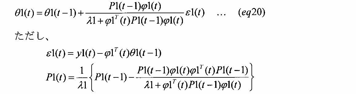
第1学習部42は、補正係数βk(t)の逆数「1/βk(t)」として第1パラメータ推定値θ1(t)を算出する。そして、Vbv算出部41を含む演算部32は、電池温度Tsに対応するβマップの電荷移動抵抗パラメータβに補正係数βk、すなわち第1パラメータ推定値θ1(t)に基づいて算出された補正係数βk(t)、を乗算することにより、電荷移動抵抗パラメータβを更新する。これにより、更新された電荷移動抵抗パラメータβが、Vbv算出部41及び電流推定部35において用いられる。すなわち、本実施形態において、演算部32は、上記電荷移動抵抗パラメータβの更新処理を行う「第1更新部(更新部)32a」を含んでいる。言い換えれば、本実施形態において、演算部32は、上記電荷移動抵抗パラメータβの更新処理を行う「第1更新部(更新部)32a」として機能する。
図12を用いて、第1学習処理の効果について説明する。図12は、低温時(例えば-15℃)における電池セル20aの端子間電圧CCVの真値及び推定値のそれぞれの推移を示す。ここで、上記推定値とは、OCV変換部33によって算出された開放端電圧OCV、Vs算出部40によって算出された直流抵抗電圧Vs、Vbv算出部41によって算出された電荷移動抵抗電圧Vbv、及び上式(eq13)に基づいて算出された分極電圧Vwの加算値に相当する。
図12に示される例では、電荷移動抵抗パラメータβの初期値が、電荷移動インピーダンスモデルを表す適切な値からずれている。このため、第1学習処理を開始してからの一定の期間においては、端子間電圧CCVの推定値はその真値から大きくずれている。しかしながら、その後、第1学習処理によって電荷移動抵抗パラメータβが逐次更新されることにより、端子間電圧CCVの推定値は、その真値と一致するようになる。
<3.第2学習処理>
図6を用いて、各演算部32における対応する電池セル20aについての第2学習処理について説明する。
この第2学習処理は、拡散インピーダンスモデル38dにおける抵抗成分項の抵抗値Rw及び容量成分項の静電容量Cwを学習するための処理である。各演算部32は、第2学習処理を行うための処理部として、図6に示すように、Vs算出部40及びVbv算出部41に加えて、第2学習部43を備えている。第2学習部43は、直流抵抗電圧Vs、電荷移動抵抗電圧Vbv、検出電流Is、及び端子間電圧CCVに基づいて、抵抗成分項の抵抗値Rw及び容量成分項の静電容量Cwを学習する。本実施形態において、第2学習部43が「第2パラメータ推定部43a」を含む。以下、第2学習部43による学習手法(学習処理)について説明する。
図6を用いて、各演算部32における対応する電池セル20aについての第2学習処理について説明する。
この第2学習処理は、拡散インピーダンスモデル38dにおける抵抗成分項の抵抗値Rw及び容量成分項の静電容量Cwを学習するための処理である。各演算部32は、第2学習処理を行うための処理部として、図6に示すように、Vs算出部40及びVbv算出部41に加えて、第2学習部43を備えている。第2学習部43は、直流抵抗電圧Vs、電荷移動抵抗電圧Vbv、検出電流Is、及び端子間電圧CCVに基づいて、抵抗成分項の抵抗値Rw及び容量成分項の静電容量Cwを学習する。本実施形態において、第2学習部43が「第2パラメータ推定部43a」を含む。以下、第2学習部43による学習手法(学習処理)について説明する。
図13に、本実施形態に係る抵抗成分項の抵抗値Rw及び容量成分項の静電容量Cwを学習するために第2学習部43で用いられる回路モデルLMを示す。この回路モデルLMは、抵抗成分項Rw及び容量成分項Cwの並列接続体に直接接続された誤差抵抗を含んでいる。図13には、誤差抵抗の抵抗値を「RE」にて示している。誤差抵抗は、電荷移動抵抗電圧Vbv及び直流抵抗電圧Vsのそれぞれに誤差が含まれ得ることに鑑みて設けられるものである。
ここで、図13に示す回路モデルLMの印加電圧Vinを下式(eq21)にて表す。


ここで上式(eq23)において、各パラメータを下式(eq24)のように表す。


第2学習部43は、算出した第2パラメータ推定値θ2(t)及び下式(eq26)に基づいて、抵抗成分項の抵抗値Rw、容量成分項の静電容量Cw、及び誤差抵抗の抵抗値REを算出する。

電荷移動抵抗電圧Vbv及び直流抵抗電圧Vsの誤差を吸収するための誤差抵抗の抵抗値REは、0近傍の値となり、場合によっては負の値となり得る。演算部32は、電池温度Ts(絶対温度T)と関係付けられた状態でメモリ31に記憶されている抵抗成分項の抵抗値Rwと容量成分項の静電容量Cwとに関する拡散インピーダンス情報を、第2学習部43により算出、すなわち学習された抵抗値Rwおよび静電容量Cwに基づいて、更新する。そして、更新された情報が電流推定部35において用いられる。すなわち、本実施形態において、演算部32が上記拡散インピーダンス情報の更新処理を行う「第2更新部32b」を含む。言い換えれば、本実施形態において、演算部32は、上記拡散インピーダンス情報の更新処理を行う「第2更新部32b」として機能する。
なお、第2学習部43は、該第2学習部43に入力されるパラメータVs、Vbv、Is、およびCCVの全てに、学習すべきRC並列回路の時定数に見合うローパスフィルタ(LPF)を適切に施してもよい。これにより、学習された抵抗値Rwおよび静電容量Cwを安定した値とすることができる。
なお、第2学習部43は、該第2学習部43に入力されるパラメータVs、Vbv、Is、およびCCVの全てに、学習すべきRC並列回路の時定数に見合うローパスフィルタ(LPF)を適切に施してもよい。これにより、学習された抵抗値Rwおよび静電容量Cwを安定した値とすることができる。
なお、演算部32の例えばSOC算出部36は、電圧センサ21によって検出された電池セル20aの端子間電圧CCVから、誤差抵抗の抵抗値RE及び検出電流Isの乗算値、直流抵抗電圧Vs、電荷移動抵抗電圧Vbv、並びに分極電圧Vwの加算値を減算することにより、開放端電圧OCVを算出してもよい。そして、SOC算出部36は、算出した開放端電圧OCV及びOCVマップに基づいて、電池セル20aのSOCを算出してもよい。
以上説明した本実施形態によれば、以下の効果が得られるようになる。
電池ECU30は、電荷移動インピーダンスモデルを、バトラーボルマー式の交換電流密度に相当するパラメータであって、電池温度Ts(あるいは絶対温度T)と相関する電荷移動抵抗パラメータβを含むモデルとした。このため、低温時においても、各電池セル20aの電流-電圧の非線形特性を精度よく表すことができる。そして、電池ECU30は、逐次最小2乗法を用いた第1学習処理により、電荷移動抵抗パラメータβを逐次更新した。このため、各電池セル20aが劣化したり、電荷移動抵抗パラメータβの初期値が適切な値からずれたりする場合であっても、該電池セル20aのSOCの推定精度の低下を回避することができる。
電池ECU30は、検出電流偏差ΔIsの絶対値が所定値Ith以上である場合に第1学習処理を行った。このため、電池セル20aの電圧変動の挙動が非線形特性を示す電荷移動抵抗が支配的になるときを判定し、この判定時において、電荷移動抵抗パラメータβを補正するための補正係数βkを算出できる。これにより、分極電圧Vwの影響による補正係数Kの誤学習を回避できる。
電池ECU30は、RC並列等価回路モデル38dに直列接続された誤差抵抗を用いた第2学習処理により、RC並列等価回路モデル38dにおける抵抗成分項の抵抗値Rw及び容量成分項の静電容量Cwを逐次更新した。このため、直流抵抗電圧Vs及び電荷移動抵抗電圧Vbvに含まれる誤差が分極電圧Vwの算出に及ぼす影響を抑制することができる。これに対し、誤差抵抗を設けない場合には、推定された抵抗成分項の抵抗値Rwに上記誤差の影響が含まれることとなり、抵抗値Rwの推定精度が低下する懸念がある。
(第2実施形態)
以下、第2実施形態について、上記第1実施形態との相違点を中心に図面を参照しつつ説明する。
本実施形態に関わる各演算部32は、対応する電池セル20aの状態の推定に用いる上式(eq9)において、電荷移動抵抗パラメータβに加えて、適合係数γを適応デジタルフィルタによって逐次同定して更新する。これは、電池セル20aの劣化等に起因して、適合係数γが適切な値(例えば、設計時に適合した値)からずれる恐れがあることに鑑みたものである。
以下、第2実施形態について、上記第1実施形態との相違点を中心に図面を参照しつつ説明する。
本実施形態に関わる各演算部32は、対応する電池セル20aの状態の推定に用いる上式(eq9)において、電荷移動抵抗パラメータβに加えて、適合係数γを適応デジタルフィルタによって逐次同定して更新する。これは、電池セル20aの劣化等に起因して、適合係数γが適切な値(例えば、設計時に適合した値)からずれる恐れがあることに鑑みたものである。
図14を用いて、電荷移動抵抗パラメータβ及び適合係数γを同定するための処理について説明する。図14に、各演算部32に設けられた、電荷移動抵抗パラメータβ及び適合係数γを同定するための処理部61を示す。この処理部61は、上記第1実施形態で説明した第1学習部42に相当する構成である。
すなわち、処理部61において同定された電荷移動抵抗パラメータβ及び適合係数γが、上記状態推定部60を構成する電流推定部35において推定電流Ieの算出に用いられる。詳しくは、電流推定部35は、入力された各パラメータβ,γで、推定電流Ieの算出に用いられる上式(eq9)の右辺に含まれる各パラメータβ,γを更新する。
図14に示すように、処理部61は、パラメータ同定部50を備えている。パラメータ同定部50は、電荷移動抵抗パラメータβを同定する第1同定部51と、適合係数γを同定する第2同定部52とを含む。
すなわち、処理部61において同定された電荷移動抵抗パラメータβ及び適合係数γが、上記状態推定部60を構成する電流推定部35において推定電流Ieの算出に用いられる。詳しくは、電流推定部35は、入力された各パラメータβ,γで、推定電流Ieの算出に用いられる上式(eq9)の右辺に含まれる各パラメータβ,γを更新する。
図14に示すように、処理部61は、パラメータ同定部50を備えている。パラメータ同定部50は、電荷移動抵抗パラメータβを同定する第1同定部51と、適合係数γを同定する第2同定部52とを含む。
まず、本実施形態に係る電荷移動抵抗パラメータβの同定手法について説明する。
電荷移動抵抗パラメータの初期値(以下「初期パラメータβmap」という。)を下式(eq27)にて表す。



電荷移動抵抗パラメータβは、上式(eq28)に示すように、電池セル20aの温度に対して指数関数的に変化するパラメータであり、具体的には例えば、電池セル20aの使用温度範囲において先の図4に示すように桁が大きく変わるような変化をし得る。このため、適応デジタルフィルタを用いる際は、電荷移動抵抗パラメータβを直接の同定対象とせず、電荷移動抵抗パラメータβを規格化した値である補正係数βkを同定対象とすることが望ましい。これは、各演算部32における最小演算単位(Least Significant Bit:LSB)に起因した電荷移動抵抗パラメータβの同定精度の低下を回避するためである。
詳しくは、電荷移動抵抗パラメータβを直接の同定対象とする構成を考える。電池セル20aの使用温度によって電荷移動抵抗パラメータβが大きく異なるため、車両の走行中に温度が変化したり、季節によって電荷移動抵抗パラメータβが収束する時間が変化したりして、電荷移動抵抗パラメータβの同定精度が低下する懸念がある。これに対し、補正係数βkは、正規化されているので、安定した補正係数βkを演算することが可能になる。また、補正係数βkを正規化することにより、桁落ちなどの懸念点も回避できるため、電荷移動抵抗パラメータβの同定精度の低下を回避できる。
また本実施形態では、上式(eq28)で表される形で初期パラメータβmapがメモリ31に記憶されている。このため、電池セル20aの使用温度範囲におけるln(βmap)の変化幅を小さくできる。これにより、初期パラメータβmapの精度を高めることができる。
電池セル20aの劣化等に起因して、図15に一点鎖線にて示すように、メモリ31に記憶されている初期パラメータβmapは、実線にて示す設計時の適合値からずれ得る。このずれは、補正係数βkにより修正できる。詳しくは、図15に示すように、劣化等に起因してアレニウスプロットのY切片が変化するため、本実施形態では、この変化を補正係数βkによって補正する。なお、上式(eq28)において、Ktは物理定数から定まる定数を示す。このため、図15の実線及び一点鎖線の傾きは、電池セル20aの劣化等の前後で変化しない。
ここで本実施形態では、上式(eq9)をそのまま用いて上式(eq16)を導く上記第1実施形態の手法とは異なり、上式(eq9)にマクローリン展開を適用する手法を採用する。詳しくは、上式(eq9)の右辺を電池セル20aに流れる電流Iについてマクローリン展開し、電流Iの1次式まで採用すると、下式(eq31)の近似式が導かれる。


一方、電圧センサ21によって検出された今回の演算周期の端子間電圧CCV(t)と、前回の演算周期の端子間電圧CCV(t-1)との差を検出電圧偏差ΔV(t)とする。検出電圧偏差ΔV(t)は、上式(eq18)を参照すると、下式(eq33)で表される。


上式(eq34),上式(eq32)から下式(eq35a)および
(eq35b)が導かれる。
(eq35b)が導かれる。




パラメータ同定部50は、検出電圧偏差ΔV(t)、検出電流偏差ΔI(t)及び直流抵抗Rsによって定まる観測値ya(t)を入力として、上式(eq37),(eq38)に基づく逐次最小2乗法により、パラメータ推定値θaを逐次同定し、同定したパラメータ推定値θaから補正係数βkを算出する。
先の図14に戻り、第1同定部51は、検出電圧偏差ΔV(t)、検出電流偏差ΔI(t)及び電池温度Tsから算出された直流抵抗Rsに基づいて、観測値ya(t)を算出する。第1同定部51は、観測値yaを入力として、上式(eq37),(eq38)に基づく逐次最小2乗法によりパラメータ推定値θaを逐次同定し、同定されたパラメータ推定値θaから補正係数βkを算出する。
処理部61は、パラメータ同定部50に加えて、電流変化量算出部53、電圧変化量算出部54、および選択部55を有している。検出電流偏差ΔI(t)は、電流変化量算出部53によって算出され、検出電圧偏差ΔV(t)は、電圧変化量算出部54によって算出される。また、直流抵抗Rsは、上述したRsマップに基づいて算出される。
続いて、本実施形態に係る適合係数γの同定手法(同定処理)について説明する。
適合係数γは、電荷移動抵抗電圧Vbvと電池セル20aに流れる電流Iとの関係を規定する比例係数である。適合係数γを可変することにより、電流I=0A近傍の傾きを変えることなく、図18に示すように、電流Iが大きい領域の電荷移動抵抗電圧Vbvを適合することができる。なお、電池セル20aが充電される場合の適合係数γcと、電池セル20aが放電される場合の適合係数γdとを分けて設定してもよい。充電側の適合係数γcは例えば0.25に設定され、放電側の適合係数γdは例えば0.14に設定される。これら適合係数γd,γcは、メモリ31に予め記憶されている。
下式(eq39)に示すように、処理部61は、時刻t-1から時刻tの間で電流Iが大きく変化する場合の検出電圧偏差ΔV(t)と検出電流偏差ΔI(t)との関係から適合係数γを逐次同定する。

ここで上式(eq39)において、各パラメータを下式(eq40)のように表す。




ここで、第1同定部51における補正係数βkの同定は、電池セル20aに流れる電流Iが小さい(例えば、所定値より小さい)場合に行われる。一方、第2同定部52における第1および第2係数γvおよびγiの同定は、電池セル20aに流れる電流Iが大きい(例えば前記所定値より大きい)場合に行われる。このため本実施形態において、演算部32は、現在の演算周期において、電荷移動抵抗パラメータβ及び適合係数γのうちいずれを同定するかを選択する選択部55を備えている。以下、図19を用いて、選択部55を含む処理部61によって実行される選択処理について説明する。この処理は、処理部61によって例えば所定の演算周期で繰り返し実行される。
この一連の処理では、まずステップS10において、選択部55は、検出電流偏差ΔI(t)の絶対値が規定値Id以上であるか否かを判定する。この処理は、上式(eq34)で示したように、各変化量ΔOCVおよびΔVwが無視できる状況であるか否かを判定するための処理である。
ステップS10において肯定判定した場合には、選択処理は、ステップS11に進む。ステップS11において、選択部55は、今回の演算周期における検出電流Is(t)の絶対値が閾値Ir未満であるとの第1の条件、及び前回の演算周期における検出電流Is(t-1)の絶対値が閾値Ir未満であるとの第2の条件の論理積が真であるか否か、すなわち、第1の条件および第2の条件が共に成立するか否かを判定する。
本実施形態において、閾値Irは、先の図16に示すように、上式(eq9)で表されるバトラーボルマー式を上式(eq31)の近似式で近似できる電流範囲SIの1/2の値であって、電池温度Tsが高いほど大きく設定される値である。ここで、電池温度Tsが高いほど閾値Irが大きく設定されるのは、先の図5に示すバトラーボルマー式において、電池セル20aに流れる電流Iが0A近傍となる場合の傾きが電池セル20aの温度が高くなるほど小さくなり、形状がより線形になっていくためである。
ステップS11において肯定判定した場合には、選択処理はステップS12に進む。ステップS12において、第1同定部51は、補正係数βkを同定する。一方、ステップS11において否定判定した場合には、選択処理はステップS13に進み、第2同定部52は、第1係数γv及び第2係数γiを同定する。
上述した選択処理により、補正係数βkを同定する機会と、第1,第2係数γv,γiを同定する機会とを適正に確保することができる。
先の図14に戻り、パラメータ同定部50により同定された補正係数βkと、第1係数γv及び第2係数γiとは電流推定部35に入力される。電流推定部35において、補正係数βkに基づいて電荷移動抵抗パラメータβが更新される。電流推定部35は、更新された電荷移動抵抗パラメータβ、第1係数γv及び第2係数γiに基づいて、推定電流Ieを算出する。
図20に、例えば電池システム10が電池システムとして車両に適用された場合における当該車両の所定の走行モードにおいて検出された端子間電圧CCV、端子間電圧の推定値Ve、及び推定値Veと端子間電圧CCVとの誤差ΔVrrの推移を示す。ここで上記推定値Veは、OCV変換部33によって算出された開放端電圧OCV、Vs算出部40によって算出された直流抵抗電圧Vs、更新された電荷移動抵抗パラメータβを用いて算出された電荷移動抵抗電圧Vbv、及び上式(eq13)に基づいて算出された分極電圧Vwの加算値に相当する。なお、図20における所定の走行モードは、LA#4モード(排気ガス測定のための走行パターンの1つ)である。
図20に示されている例は、誤差ΔVrrが大きくなりやすい低温時(例えば-20℃)における上記端子間電圧CCV、端子間電圧の推定値Ve、及び推定値Veと端子間電圧CCVとの誤差ΔVrrの推移を示す。低温時においても、誤差ΔVrrが非常に小さい状態に維持されている。このため図20では、端子間電圧CCVの推移とその推定値Veの推移とがほぼ重なっている。
なお図21に、図20において示したデータ期間における検出電流Isと端子間電圧CCVの推定値(Veで示す)および端子間電圧CCVの検出値(CCVで示す)との相関図を示した。このように本実施形態では、低温時においても、検出電流Is及び端子間電圧CCVの推定値Veの間の非線形特性を高精度に表現でき、電池セル20aの端子間電圧CCVを高精度に推定できる。これに対し、抵抗及びコンデンサを組合せただけの従来の電池モデルでは、上記非線形特性を表現することは困難である。
以上説明した本実施形態によっても、電荷移動インピーダンスモデルを適正に更新することができる。これにより、端子間電圧CCVの推定電圧Veの算出精度を高めることができる。
(その他の実施形態)
なお、上記各実施形態は、以下のように変更して実施してもよい。
なお、上記各実施形態は、以下のように変更して実施してもよい。
上記第1実施形態において、上式(eq17)に代えて、下式(eq44)に基づいて、補正係数βkを用いることなく電荷移動抵抗パラメータβを直接同定してもよい。

上記第1実施形態では、電池セル20aの状態として、SOCを推定したがこれに限らない。例えば、規定時間に渡って電池セル20aから放電可能な最大電力を推定したり、電池セル20aの劣化状態を推定したりしてもよい。
上記第1実施形態において、第2学習処理は必須ではない。
上記第2実施形態において、上式(eq27)に従う形で初期パラメータβmapを、例えば情報VTIの一部としてメモリ31に記憶してもよい。
上記第2実施形態では、初期パラメータβmapの自然対数を電池温度Tsの逆数に対する1次式となる形で数式化し、例えば情報VTIの一部としてメモリ31に記憶したがこれに限らない。例えば、初期パラメータβmapの自然対数を電池温度Tsの逆数に対する1次式となる形でマップ化して、例えば情報VTIの一部としてメモリ31に記憶してもよい。この場合、各演算部32は、記憶されている初期パラメータβmapの自然対数値の中から、電池温度Tsに対応する自然対数値を選択する。そして、各演算部32は、選択した自然対数値を初期パラメータβmapに変換し、上式(eq29)の「β=βk×βmap」なる関係に基づいて電荷移動抵抗パラメータβを算出する。なお、初期パラメータβmapの自然対数をマップ化してメモリ31に記憶させる構成を採用する場合、電池温度Tsを少なくとも3点計測することにより、この計測された少なくとも3つの電池温度Tsの値に基づいて、該マップを作成することができる。このため、マップの適合作業を容易に行うことができる。
上記第2実施形態の図19において、0A近傍の直線性が保たれているなら電池セル20aが充電される場合と放電される場合とで閾値Irを異なる値に設定してもよい。また、電池セル20aの使い方で、放電電流及び充電電流のそれぞれの大きさが異なるような場合、0A近傍の直線性が保たれない領域でも成立する第1実施形態と、第2実施形態の第2同定部52とを組み合わせる形態を採用してもよい。さらに、一般的に電池セル20aが充電される場合の適合係数γcと、電池セル20aが放電される場合の適合係数γdとが異なる場合が多いので、充電時と放電時とでそれぞれγcとγdを分けて同定すると精度向上に有効である。
上記第2実施形態において、図19のステップS11で肯定判定された場合にも、第1,第2係数γv,γiを同定する機会を確保してもよい。
上記第2実施形態において、電流推定部35で用いられる抵抗成分項の抵抗値Rw及び容量成分項の静電容量Cwを、上記第1実施形態の図6で説明した第2学習部43によって学習してもよい。
電池セル20aとしては、リチウムイオン2次電池に限らず、ニッケル水素電池等、他の2次電池であってもよい。
上記各実施形態において、各処理に用いる電池温度としては、温度センサ22の検出値に限らず、様々な公知の電池温度推定手法の何れかを用いることhにより推定された電池温度であってもよい。
本発明の適用対象としては、車両に限らない。
20a…電池セル、30…電池ECU。
Claims (15)
- 2次電池(20a)の直流抵抗(Rs)を表す直流抵抗モデル、前記2次電池の電荷移動インピーダンスを表すモデルであって、バトラーボルマー式から導かれ、交換電流密度と相関のある電荷移動抵抗パラメータ(β)を含む電荷移動インピーダンスモデル、および抵抗とキャパシタとの並列接続体を含むRC等価回路モデルであって、前記2次電池の拡散インピーダンスを表す拡散インピーダンスモデル、の直列接続体により構成された当該2次電池の電池モデルにおける前記電荷移動インピーダンスモデルを、前記2次電池に流れる電流検出値の変化量に基づいて、前記バトラーボルマー式によって規定される前記2次電池に流れる電流及び前記電荷移動抵抗の電位差間の第1の関係を、前記2次電池に実際に流れる電流値及び前記電荷移動抵抗の実際の電位差の値の間の第2の関係に近づけるように、更新する処理を行う更新部(30)と、
前記更新部によって更新された前記電荷移動インピーダンスモデルを含む前記電池モデルに基づいて、前記2次電池の状態を推定する状態推定部(30)と、を備えることを特徴とする電池状態推定装置。 - 前記更新部は、所定の演算周期に基づいて前記電荷移動インピーダンスモデルを更新し、前記状態推定部は、前記所定の演算周期に基づいて前記2次電池の状態を推定しており、
今回の演算周期における前記2次電池に流れる電流検出値と、前回の演算周期における前記2次電池に流れる電流検出値との偏差である第1偏差を算出する第1偏差算出部(30)と、
前記電荷移動インピーダンスモデルに基づいて推定した今回の演算周期における前記2次電池に流れる推定電流と、前記電荷移動インピーダンスモデルに基づいて推定した前回の演算周期における前記2次電池に流れる推定電流との偏差である推定電流偏差、又は前記推定電流偏差に応じた値のいずれかである第2偏差を算出する第2偏差算出部(30)と、
前記第1偏差及び前記第2偏差のそれぞれに基づいて、前記第2偏差を前記第1偏差に近づけるための補正係数(βk)を逐次最小2乗法により推定するパラメータ推定部(30)と、を備え、
前記更新部は、前記電荷移動インピーダンスモデルを更新する処理として、前記パラメータ推定部によって推定された前記補正係数に基づいて、前記電荷移動抵抗パラメータを更新する処理を行う請求項1に記載の電池状態推定装置。 - 前記電荷移動抵抗パラメータβは、定数をα,γ、前記2次電池に流れる電流をI、前記2次電池の温度をT、前記電荷移動抵抗の電位差をVbvと定義すると、以下の第1式
(第1式)
を満たすパラメータである請求項2記載の電池状態推定装置。 - 前記第2偏差算出部は、今回の演算周期において算出した前記電荷移動抵抗の電位差をVbv(t)、前回の演算周期において算出した前記電荷移動抵抗の電位差をVbv(t-1)と定義すると、今回の演算周期における前記第2偏差ΔF(t)を以下の第2式
(第2式)
に基づいて算出し、
前記パラメータ推定部は、定数をβ0、前記補正係数をβkと定義すると、前記第1偏差が、前記定数β0および補正係数βkで表された以下の第3式に基づく前記第2偏差と一致するような前記補正係数を逐次最小2乗法により推定する請求項3に記載の電池状態推定装置。
(第3式)
- 前記第2偏差算出部は、前記2次電池に流れる電流の検出値の1演算周期における変化量が所定値以上であることを条件として、前記2次電池の端子間電圧検出値から前記直流抵抗の電位差を減算することにより、前記電荷移動インピーダンスの電位差を算出する請求項4に記載の電池状態推定装置。
- 前記パラメータ推定部を第1パラメータ推定部とし、
前記更新部を第1更新部とし、
前記RC等価回路モデルを構成する前記並列接続体に誤差抵抗を直列接続したモデルに基づいて、前記RC等価回路モデルを構成する前記抵抗の抵抗値及び前記キャパシタの静電容量を逐次最小2乗法により推定する第2パラメータ推定部(30)と、
前記第2パラメータ推定部によって推定された前記抵抗の抵抗値及び前記キャパシタの静電容量で、前記RC等価回路モデルを構成する前記抵抗の抵抗値及び前記キャパシタの静電容量を更新する第2更新部(30)と、をさらに備える請求項2~5のいずれか1項に記載の電池状態推定装置。 - 前記バトラーボルマー式には、該バトラーボルマー式の前記電荷移動抵抗の電位差方向における拡大又は縮小を規定する第1係数(γv)と、該バトラーボルマー式の前記2次電池に流れる電流方向における拡大又は縮小を規定する第2係数(γi)とが含まれており、
前記2次電池に流れる電流検出値の絶対値が閾値未満であることを条件として、前記2次電池に流れる電流検出値の変化量と、前記2次電池の端子間電圧検出値の変化量とに基づいて、逐次最小2乗法により、前記2次電池に流れる電流及び前記電荷移動抵抗の電位差間の第1の関係を規定する1次式の傾きの相関値として前記電荷移動抵抗パラメータを同定する第1同定部(30)と、
前記2次電池に流れる電流検出値の変化量と、前記2次電池の端子間電圧検出値の変化量とに基づいて、逐次最小2乗法により前記第1係数を同定し、前記第1係数を同定した演算周期の次の演算周期において、同定した前記第1係数を前記第2係数に適用する第2同定部(30)と、を備え、
前記更新部は、前記更新する処理として、前記第1同定部によって同定された前記電荷移動抵抗パラメータと、前記第2同定部によって同定された前記第1係数及び前記第2係数とに基づいて、前記電荷移動インピーダンスモデルを更新する処理を行う請求項1に記載の電池状態推定装置。 - 前記電荷移動抵抗パラメータは、前記2次電池に流れる電流を独立変数とし、前記電荷移動抵抗の電位差を従属変数とする逆双曲線正弦関数において前記2次電池に流れる電流と前記電荷移動抵抗の電位差との間の第1の関係を定めるパラメータであって、かつ、前記2次電池の温度の逆数を独立変数とする指数関数で規定されるパラメータである請求項7に記載の電池状態推定装置。
- 前記電荷移動抵抗パラメータβ、前記第1係数γv及び前記第2係数γiは、定数をα、前記2次電池に流れる電流をI、前記2次電池の温度をT、前記電荷移動抵抗の電位差をVbvと定義すると、以下の第4式
(第4式)
満たすパラメータである請求項8記載の電池状態推定装置。 - 上記第4式を前記2次電池に流れる電流についてマクローリン展開した式であって、前記2次電池に流れる電流を独立変数とし、前記電荷移動抵抗の電位差を従属変数とする1次式が近似式として定義されており、
前記閾値は、上記第4式で表される前記電荷移動抵抗の電位差を前記近似式から定まる前記電荷移動抵抗の電位差で近似できる前記電流の範囲に基づいて設定されており、
前記2次電池の温度と関係付けられて前記電荷移動抵抗パラメータに係る情報が記憶されている記憶部(31)と、
前記2次電池の温度検出値と、前記記憶部に記憶されている前記電荷移動抵抗パラメータに係る情報とに基づいて、当該電荷移動抵抗パラメータに係る情報における前記温度検出値に対応する情報を算出する算出部(35a)と、を備え、
前記第1同定部は、
前記電荷移動抵抗パラメータに係る情報をβmap、前記電荷移動抵抗の電位差の変化量をΔVbvと定義すると、前記電流検出値の変化量ΔI及び前記端子間電圧検出値の変化量ΔVに基づいて、逐次最小2乗法により、以下の第5式を満たす補正係数βkを同定する補正係数同定部(35b)と、
(第5式)
前記補正係数同定部により同定された前記補正係数に基づいて、前記算出部により算出された、前記電荷移動抵抗パラメータに係る情報における前記温度検出値に対応する情報を補正する補正部(35c)と、を含む請求項9記載の電池状態推定装置。 - 前記電荷移動抵抗パラメータに係る情報βmapは、予め適合された前記電荷移動抵抗パラメータであって、以下の第6式で表される初期パラメータであり、
(第6式)
前記記憶部は、定数をKt,β0と定義すると、以下の第7式に従う形で前記2次電池の温度の逆数と関係付けて前記初期パラメータを記憶している請求項10記載の電池状態推定装置。
(第7式)
- 前記第2同定部は、今回の演算周期における前記電流検出値をI(t)、前回の演算周期における前記電流検出値をI(t-1)と定義すると、逐次最小2乗法により、以下の第8式を満たす前記第1係数γvを同定する請求項11に記載の電池状態推定装置。
(第8式)
- 前記第1同定部は、前記電流検出値の1演算周期における変化量が規定値以上であることを条件として、前記補正係数を同定し、
前記第2同定部は、前記電流検出値の1演算周期における変化量が前記規定値以上であることを条件として、前記第1係数を同定する請求項10~12のいずれか1項に記載の電池状態推定装置。 - 前記第1同定部は、前記直流抵抗をRsと定義すると、以下の第9式で表される観測値y(t)を逐次最小2乗法による前記補正係数の同定に用い、
(第9式)
前記第2同定部は、上記第9式で表される前記観測値y(t)を逐次最小2乗法による前記第1係数の同定に用いる請求項13記載の電池状態推定装置。 - 前記第2同定部は、前記2次電池に流れる電流検出値の絶対値が前記閾値以上であることを条件として、前記第1係数を同定する請求項7~14のいずれか1項に記載の電池状態推定装置。
Priority Applications (2)
| Application Number | Priority Date | Filing Date | Title |
|---|---|---|---|
| DE112016001065.6T DE112016001065B4 (de) | 2015-03-06 | 2016-03-07 | Batteriezustandsschätzvorrichtung |
| US15/556,138 US10663524B2 (en) | 2015-03-06 | 2016-03-07 | Battery state estimating apparatus |
Applications Claiming Priority (4)
| Application Number | Priority Date | Filing Date | Title |
|---|---|---|---|
| JP2015-045161 | 2015-03-06 | ||
| JP2015045161 | 2015-03-06 | ||
| JP2015231112A JP6455409B2 (ja) | 2015-03-06 | 2015-11-26 | 電池状態推定装置 |
| JP2015-231112 | 2015-11-26 |
Publications (1)
| Publication Number | Publication Date |
|---|---|
| WO2016143728A1 true WO2016143728A1 (ja) | 2016-09-15 |
Family
ID=56880208
Family Applications (1)
| Application Number | Title | Priority Date | Filing Date |
|---|---|---|---|
| PCT/JP2016/056932 Ceased WO2016143728A1 (ja) | 2015-03-06 | 2016-03-07 | 電池状態推定装置 |
Country Status (2)
| Country | Link |
|---|---|
| DE (1) | DE112016001065B4 (ja) |
| WO (1) | WO2016143728A1 (ja) |
Cited By (6)
| Publication number | Priority date | Publication date | Assignee | Title |
|---|---|---|---|---|
| CN107037365A (zh) * | 2016-11-16 | 2017-08-11 | 上海中兴派能能源科技股份有限公司 | 一种动力锂电池电芯的测量方法 |
| CN112114255A (zh) * | 2020-09-18 | 2020-12-22 | 中国计量大学 | 一种基于联合集合卡尔曼滤波的锂电池荷电状态估计方法 |
| CN115562073A (zh) * | 2022-10-17 | 2023-01-03 | 上海科梁信息科技股份有限公司 | Rc参数调节方法、装置、电子设备及存储介质 |
| EP4459302A1 (en) * | 2023-04-26 | 2024-11-06 | SK On Co., Ltd. | Method and device for determining an abnormality in a battery |
| JP2025093692A (ja) * | 2023-12-12 | 2025-06-24 | 本田技研工業株式会社 | 情報処理装置、情報処理方法、およびプログラム |
| CN121027874A (zh) * | 2025-10-30 | 2025-11-28 | 成都星辰瀑布电力科技有限公司 | 电化学电池的电池状态监测方法、系统、等效电路及介质 |
Families Citing this family (1)
| Publication number | Priority date | Publication date | Assignee | Title |
|---|---|---|---|---|
| WO2024063418A2 (ko) * | 2022-09-23 | 2024-03-28 | 주식회사 엘지에너지솔루션 | 배터리 진단 장치 및 배터리 진단 방법 |
Citations (3)
| Publication number | Priority date | Publication date | Assignee | Title |
|---|---|---|---|---|
| JP2008058278A (ja) * | 2006-09-04 | 2008-03-13 | Toyota Motor Corp | 二次電池の内部状態推定装置、二次電池の内部状態推定方法、プログラム、および記録媒体 |
| WO2011118080A1 (ja) * | 2010-03-23 | 2011-09-29 | 古河電気工業株式会社 | 電池内部状態推定装置および電池内部状態推定方法 |
| US20160039419A1 (en) * | 2014-05-12 | 2016-02-11 | GM Global Technology Operations LLC | Battery state estimation systems and methods using a nonlinear resistance element |
Family Cites Families (2)
| Publication number | Priority date | Publication date | Assignee | Title |
|---|---|---|---|---|
| DE10126891A1 (de) | 2001-06-01 | 2002-12-05 | Vb Autobatterie Gmbh | Verfahren zur Vorhersage der Belastbarkeit eines elektrochemischen Elementes |
| JP3747826B2 (ja) | 2001-09-05 | 2006-02-22 | 日産自動車株式会社 | 二次電池の充電率推定装置 |
-
2016
- 2016-03-07 WO PCT/JP2016/056932 patent/WO2016143728A1/ja not_active Ceased
- 2016-03-07 DE DE112016001065.6T patent/DE112016001065B4/de active Active
Patent Citations (3)
| Publication number | Priority date | Publication date | Assignee | Title |
|---|---|---|---|---|
| JP2008058278A (ja) * | 2006-09-04 | 2008-03-13 | Toyota Motor Corp | 二次電池の内部状態推定装置、二次電池の内部状態推定方法、プログラム、および記録媒体 |
| WO2011118080A1 (ja) * | 2010-03-23 | 2011-09-29 | 古河電気工業株式会社 | 電池内部状態推定装置および電池内部状態推定方法 |
| US20160039419A1 (en) * | 2014-05-12 | 2016-02-11 | GM Global Technology Operations LLC | Battery state estimation systems and methods using a nonlinear resistance element |
Cited By (8)
| Publication number | Priority date | Publication date | Assignee | Title |
|---|---|---|---|---|
| CN107037365A (zh) * | 2016-11-16 | 2017-08-11 | 上海中兴派能能源科技股份有限公司 | 一种动力锂电池电芯的测量方法 |
| CN112114255A (zh) * | 2020-09-18 | 2020-12-22 | 中国计量大学 | 一种基于联合集合卡尔曼滤波的锂电池荷电状态估计方法 |
| CN112114255B (zh) * | 2020-09-18 | 2023-02-28 | 中国计量大学 | 一种基于联合集合卡尔曼滤波的锂电池荷电状态估计方法 |
| CN115562073A (zh) * | 2022-10-17 | 2023-01-03 | 上海科梁信息科技股份有限公司 | Rc参数调节方法、装置、电子设备及存储介质 |
| EP4459302A1 (en) * | 2023-04-26 | 2024-11-06 | SK On Co., Ltd. | Method and device for determining an abnormality in a battery |
| JP2025093692A (ja) * | 2023-12-12 | 2025-06-24 | 本田技研工業株式会社 | 情報処理装置、情報処理方法、およびプログラム |
| JP7825606B2 (ja) | 2023-12-12 | 2026-03-06 | 本田技研工業株式会社 | 情報処理装置、情報処理方法、およびプログラム |
| CN121027874A (zh) * | 2025-10-30 | 2025-11-28 | 成都星辰瀑布电力科技有限公司 | 电化学电池的电池状态监测方法、系统、等效电路及介质 |
Also Published As
| Publication number | Publication date |
|---|---|
| DE112016001065T5 (de) | 2018-01-04 |
| DE112016001065B4 (de) | 2021-12-23 |
Similar Documents
| Publication | Publication Date | Title |
|---|---|---|
| JP6455409B2 (ja) | 電池状態推定装置 | |
| US10890625B2 (en) | Battery state estimating device | |
| WO2016143728A1 (ja) | 電池状態推定装置 | |
| JP4692246B2 (ja) | 二次電池の入出力可能電力推定装置 | |
| JP6409721B2 (ja) | 電池状態推定装置 | |
| JP5616464B2 (ja) | 二次電池の充電状態推定装置 | |
| CN103003709B (zh) | 电池状态估计装置以及电池状态估计方法 | |
| US20150106044A1 (en) | Estimating of the state of charge of a battery | |
| CN109669131B (zh) | 一种工况环境下动力电池soc估算方法 | |
| JP6428402B2 (ja) | 電池エネルギ予測装置 | |
| WO2016067587A1 (ja) | バッテリのパラメータ推定装置 | |
| WO1999061929A1 (fr) | Moyen permettant d'evaluer l'etat de charge d'une batterie et procede permettant d'evaluer l'etat de decharge d'une batterie | |
| WO2017119393A1 (ja) | 状態推定装置、状態推定方法 | |
| CN105283773A (zh) | 电池的健康度估计装置以及健康度估计方法 | |
| JP5163542B2 (ja) | 二次電池の入出力可能電力推定装置 | |
| CN110716146A (zh) | 一种动力电池开路电压的估计方法 | |
| WO2017179175A1 (ja) | 推定装置、推定プログラムおよび充電制御装置 | |
| WO2019116815A1 (ja) | 二次電池監視装置、二次電池状態演算装置および二次電池状態推定方法 | |
| CN110031715B (zh) | 用于识别第一电能量存储器单元中的内部短路的方法 | |
| CN112415409A (zh) | 估算电池容量的方法和装置、存储介质及车辆 | |
| WO2018025306A1 (ja) | 推定装置、推定プログラムおよび充電制御装置 | |
| JP2022113377A (ja) | 電池抵抗算出システム及び劣化検出システム | |
| JP2017003349A (ja) | 電池状態推定装置 | |
| JP4720364B2 (ja) | 二次電池の内部抵抗推定装置 | |
| JP7251737B2 (ja) | 推定装置 |
Legal Events
| Date | Code | Title | Description |
|---|---|---|---|
| 121 | Ep: the epo has been informed by wipo that ep was designated in this application |
Ref document number: 16761696 Country of ref document: EP Kind code of ref document: A1 |
|
| WWE | Wipo information: entry into national phase |
Ref document number: 112016001065 Country of ref document: DE Ref document number: 15556138 Country of ref document: US |
|
| 122 | Ep: pct application non-entry in european phase |
Ref document number: 16761696 Country of ref document: EP Kind code of ref document: A1 |