WO2016143605A1 - 排気管燃料噴射器用閉塞防止装置 - Google Patents
排気管燃料噴射器用閉塞防止装置 Download PDFInfo
- Publication number
- WO2016143605A1 WO2016143605A1 PCT/JP2016/056228 JP2016056228W WO2016143605A1 WO 2016143605 A1 WO2016143605 A1 WO 2016143605A1 JP 2016056228 W JP2016056228 W JP 2016056228W WO 2016143605 A1 WO2016143605 A1 WO 2016143605A1
- Authority
- WO
- WIPO (PCT)
- Prior art keywords
- exhaust pipe
- fuel injector
- pipe fuel
- exhaust
- combustion engine
- Prior art date
- Legal status (The legal status is an assumption and is not a legal conclusion. Google has not performed a legal analysis and makes no representation as to the accuracy of the status listed.)
- Ceased
Links
Images
Classifications
-
- F—MECHANICAL ENGINEERING; LIGHTING; HEATING; WEAPONS; BLASTING
- F01—MACHINES OR ENGINES IN GENERAL; ENGINE PLANTS IN GENERAL; STEAM ENGINES
- F01N—GAS-FLOW SILENCERS OR EXHAUST APPARATUS FOR MACHINES OR ENGINES IN GENERAL; GAS-FLOW SILENCERS OR EXHAUST APPARATUS FOR INTERNAL-COMBUSTION ENGINES
- F01N3/00—Exhaust or silencing apparatus having means for purifying, rendering innocuous, or otherwise treating exhaust
- F01N3/02—Exhaust or silencing apparatus having means for purifying, rendering innocuous, or otherwise treating exhaust for cooling, or for removing solid constituents of, exhaust
- F01N3/021—Exhaust or silencing apparatus having means for purifying, rendering innocuous, or otherwise treating exhaust for cooling, or for removing solid constituents of, exhaust by means of filters
- F01N3/023—Exhaust or silencing apparatus having means for purifying, rendering innocuous, or otherwise treating exhaust for cooling, or for removing solid constituents of, exhaust by means of filters using means for regenerating the filters, e.g. by burning trapped particles
- F01N3/025—Exhaust or silencing apparatus having means for purifying, rendering innocuous, or otherwise treating exhaust for cooling, or for removing solid constituents of, exhaust by means of filters using means for regenerating the filters, e.g. by burning trapped particles using fuel burner or by adding fuel to exhaust
Definitions
- the present invention relates to an exhaust pipe fuel injector blockage prevention device for preventing blockage of an exhaust pipe fuel injector.
- an exhaust pipe fuel injector that injects fuel into exhaust gas in order to raise the exhaust gas temperature and burn particulate matter collected in the diesel particulate filter Is employed (see, for example, Patent Document 1).
- the exhaust pipe fuel injector determines clogging according to how much the catalyst temperature before fuel addition and the catalyst temperature after fuel addition rises, and it is determined that the exhaust pipe fuel injector is clogged.
- the after-injection amount is increased to increase the exhaust temperature to remove deposits (see, for example, Patent Document 2).
- an object of the present invention is to provide an exhaust pipe fuel injector blockage prevention device capable of improving fuel efficiency as compared with the conventional art.
- the present invention devised to achieve this object includes an obstruction prevention injection execution unit for driving an exhaust pipe fuel injector, and an operation for driving the exhaust pipe fuel injector even when the exhaust temperature exceeds a threshold value.
- a blockage prevention injection holding unit for holding the drive of the exhaust pipe fuel injector by the blockage prevention injection execution unit until an integrated value of the internal combustion engine speed becomes equal to or greater than a threshold value.
- the present invention provides a blockage preventing injection execution unit for driving an exhaust pipe fuel injector, and an internal combustion engine speed after driving the exhaust pipe fuel injector even when an exhaust gas temperature exceeds a threshold value.
- a blockage prevention injection holding unit that holds the drive of the exhaust pipe fuel injector by the blockage prevention injection execution unit until the integrated value of the above time becomes equal to or greater than a threshold value.
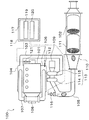
- an automobile 100 to which the present invention is applied is a particulate matter that collects particulate matter (PM) in exhaust gas discharged from an internal combustion engine 101 such as a diesel engine and is discharged into the atmosphere.
- a diesel particulate filter 102 for reducing the amount of discharged substances is provided, and when the amount of particulate matter deposited on the diesel particulate filter 102 exceeds a threshold value, the temperature of the diesel particulate filter 102 can be regenerated (for example, 500).
- the particulate matter collected in the diesel particulate filter 102 is maintained at a recyclable temperature for a regeneration duration (for example, about 5 minutes).
- the diesel particulate filter 102 is regenerated by burning it. There.
- the internal combustion engine 101 is connected to an intake pipe 103 and is connected to an intake manifold 104 that branches intake air introduced into the internal combustion engine 101 through the intake pipe 103 into each combustion chamber of the internal combustion engine 101, and an exhaust pipe 105. And an exhaust manifold 106 that joins exhaust discharged from the combustion chambers of the internal combustion engine 101 to the exhaust pipe 105.
- intake air is introduced into the internal combustion engine 101 through the intake pipe 103 and exhaust gas is discharged from the internal combustion engine 101 through the exhaust pipe 105 through a combustion stroke.
- the intake air introduced into the internal combustion engine 101 is purified through the intake air purification device 109 installed in the intake pipe 103 and exhausted to the atmosphere through the exhaust gas purification device 110 installed in the exhaust pipe 105.
- the exhaust is purified.
- an exhaust temperature detector 112 for detecting the exhaust temperature in the vicinity of the exhaust pipe fuel injector 116 is installed in the exhaust manifold 106. Note that the exhaust temperature detector 112 may be installed in the vicinity of the exhaust pipe fuel injector 116 instead of the exhaust manifold 106.
- the exhaust emission control device 110 includes a soluble organic (SOF) component in particulate matter contained in the exhaust gas discharged into the atmosphere through the exhaust pipe 105 and nitrogen monoxide in the exhaust gas discharged into the atmosphere through the exhaust pipe 105.
- An oxidation catalyst (DOC) 111 that oxidizes the diesel catalyst, and a diesel particulate filter 102 installed on the exhaust gas downstream side of the oxidation catalyst 111.
- the supercharger 113 is installed between the intake pipe 103 and the exhaust pipe 105, the prime mover 114 of the supercharger 113 installed in the exhaust pipe 105 is discharged from the internal combustion engine 101. As a result, the compressor 115 of the supercharger 113 installed in the intake pipe 103 is driven, and the intake air introduced into the internal combustion engine 101 through the intake pipe 103 is supercharged.
- the automobile 100 is discharged into the atmosphere through the exhaust pipe 105 by adding unburned fuel to the exhaust discharged into the atmosphere through the exhaust pipe 105 and oxidizing and burning the unburned fuel with the oxidation catalyst 111.
- an exhaust pipe fuel injector 116 for injecting fuel in accordance with the indicated fuel injection amount is mounted on the exhaust upstream side of the diesel particulate filter 102.
- the actual fuel injection amount gradually decreases due to the blockage by the deposit, and there is a possibility that the fuel cannot be injected according to the commanded fuel injection amount.
- An exhaust pipe fuel injector blockage prevention device 117 for preventing the pipe fuel injector 116 from being blocked is required.
- An exhaust pipe fuel injector blockage prevention device 117 is realized by a program, hardware, and the like, and is mounted on an internal combustion engine control device (ECU) 118.
- the exhaust pipe fuel injector A blockage prevention injection execution unit 119 for driving 116 is provided.
- the blockage prevention injection execution unit 119 drives the exhaust pipe fuel injector 116 to perform blockage prevention injection that injects fuel into the exhaust gas, thereby depositing the deposit that causes the blockage of the exhaust pipe fuel injector 116 together with the fuel. Eject into exhaust and remove.
- the blockage preventing injection execution unit Blocking prevention injection by 119 is performed. In this case, since fuel is frequently injected, deterioration of fuel consumption cannot be avoided.
- the exhaust pipe fuel injector blockage prevention device 117 is realized by a program, hardware, and the like, and is mounted on the internal combustion engine control device 118. Even if the exhaust temperature becomes equal to or higher than the threshold value, the exhaust pipe fuel injector 116 is The blockage prevention injection holding unit for holding the drive of the exhaust pipe fuel injector 116 by the blockage prevention injection execution unit 119 until the integrated value of the time when the internal combustion engine rotation speed after driving becomes equal to or higher than the idle rotation speed exceeds the threshold value. 120.
- the threshold value of the integrated value of the time during which the internal combustion engine speed after the exhaust pipe fuel injector 116 is driven becomes equal to or higher than the idle speed is such that the exhaust pipe fuel injector 116 continues to receive heat damage above the guaranteed temperature. Is determined based on the maximum integrated value at which performance degradation does not occur or the maximum integrated value at which performance degradation does not occur due to blockage of the exhaust pipe fuel injector 116, and the exhaust temperature threshold value is guaranteed by the exhaust pipe fuel injector. It is determined based on the oxidation temperature of the fuel that causes temperature and deposits.
- the internal combustion engine speed may be detected indirectly based on the crank angle detected by the crank angle detector, or directly by the internal combustion engine speed detector 121 that detects the rotational speed of the rotating shaft. May be detected.
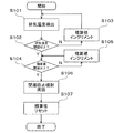
- the exhaust pipe fuel injector blockage prevention device 117 detects the exhaust temperature by the exhaust temperature detector 112 in step S101, and estimates the ambient temperature of the exhaust pipe fuel injector 116.
- the blockage preventing injection holding unit 120 determines whether the estimated exhaust gas temperature around the exhaust pipe fuel injector 116 is equal to or higher than a threshold value. If the exhaust gas temperature is not higher than the threshold value, the internal combustion engine is determined in step S103. The integrated value of the time when the rotation speed is equal to or higher than the idle rotation speed is incremented, and the process returns to step S101.
- the integrated value of the time when the internal combustion engine speed becomes equal to or higher than the idle speed by the blockage preventing injection holding unit 120 in step S104 is the threshold value. If the accumulated value of the time when the internal combustion engine speed becomes equal to or greater than the idle speed is not equal to or greater than the threshold value, the accumulated value where the internal combustion engine speed is equal to or greater than the idle speed is incremented in step S105. The process returns to step S104.
- the exhaust pipe fuel injector 116 is driven by the obstruction prevention injection execution unit 119 in Step S106 to implement the obstruction prevention injection.
- the blockage preventing injection holding unit 120 resets the integrated value.
- the exhaust pipe fuel injector blockage prevention device 117 attempts to remove deposits when the exhaust temperature in the vicinity of the exhaust pipe fuel injector 116 is at least the threshold value and the integrated value is at least the threshold value. Otherwise, defer deposit removal.
- the fuel injection for preventing the exhaust pipe fuel injector 116 from being blocked can be minimized, and the fuel consumption can be improved as compared with the prior art.
- the travel distance (for example, calculated based on the rotation pulse of the wheel shaft) after the exhaust pipe fuel injector 116 is driven even when the exhaust gas temperature becomes equal to or higher than the threshold value by the blocking prevention injection holding unit 120 is the threshold value. Until this is the case, it is conceivable to suspend driving of the exhaust pipe fuel injector 116 by the blocking prevention injection execution unit 119.
- the travel distance after the exhaust pipe fuel injector 116 is driven. Even if the value does not exceed the threshold value, the drive time of the internal combustion engine 101 may be long. In this case, the exhaust pipe fuel injector 116 may be blocked.
- the exhaust pipe fuel injector blockage prevention device 117 the internal combustion engine speed after the exhaust pipe fuel injector 116 is driven as the reference for suspending the drive of the exhaust pipe fuel injector 116 is the idle speed. Since the integrated value of the above time is used, it is possible to prevent the exhaust pipe fuel injector 116 from being blocked even in a city delivery vehicle or the like.
- the drive of the exhaust pipe fuel injector 116 is suspended based on the integrated value of the internal combustion engine speed after the exhaust pipe fuel injector 116 is driven.
- the driving of the exhaust pipe fuel injector 116 may be suspended based on the integrated value of the time when the engine speed after the exhaust pipe fuel injector 116 is driven becomes equal to or higher than the idle speed.
- the threshold value of the integrated value of the time during which the internal combustion engine speed after the exhaust pipe fuel injector 116 is driven becomes equal to or higher than the idle speed is such that the exhaust pipe fuel injector 116 continues to receive heat damage above the guaranteed temperature. It is determined based on the maximum integrated value at which performance degradation does not occur or the maximum integrated value at which performance degradation does not occur due to blockage of the exhaust pipe fuel injector 116.
Landscapes
- Engineering & Computer Science (AREA)
- Chemical & Material Sciences (AREA)
- Combustion & Propulsion (AREA)
- Mechanical Engineering (AREA)
- General Engineering & Computer Science (AREA)
- Processes For Solid Components From Exhaust (AREA)
- Exhaust Gas After Treatment (AREA)
- Electrical Control Of Air Or Fuel Supplied To Internal-Combustion Engine (AREA)
Abstract
従来よりも燃費を改善することが可能な排気管燃料噴射器用閉塞防止装置を提供する。 排気管燃料噴射器116を駆動させる閉塞防止噴射実施部119と、排気温度が閾値以上になっても排気管燃料噴射器116を駆動させてからの内燃機関回転数の積算値が閾値以上になるまでは閉塞防止噴射実施部119による排気管燃料噴射器116の駆動を保留する閉塞防止噴射保留部120と、を備えている排気管燃料噴射器用閉塞防止装置117である。
Description
本発明は、排気管燃料噴射器の閉塞を防止する排気管燃料噴射器用閉塞防止装置に関する。
従来、ディーゼル機関が搭載されている自動車においては、排気温度を昇温させてディーゼルパティキュレートフィルタに捕集されている粒子状物質を燃焼させるために排気中に燃料を噴射する排気管燃料噴射器が採用されている(例えば、特許文献1を参照)。
排気管燃料噴射器は、燃料添加前の触媒温度と、燃料添加後の触媒温度を比較してどれだけ上昇したかによって詰りを判定し、排気管燃料噴射器が詰っていると判定されるとアフター噴射量を増量して排気温度を上昇させデポジットを除去している(例えば、特許文献2を参照)。
しかしながら、排気温度が閾値以上である時に排気管燃料噴射器で燃料を噴射する場合、頻繁に燃料の噴射が行われるため、燃費の悪化を避けられない。
そこで、本発明の目的は、従来よりも燃費を改善することが可能な排気管燃料噴射器用閉塞防止装置を提供することにある。
この目的を達成するために創案された本発明は、排気管燃料噴射器を駆動させる閉塞防止噴射実施部と、排気温度が閾値以上になっても前記排気管燃料噴射器を駆動させてからの内燃機関回転数の積算値が閾値以上になるまでは前記閉塞防止噴射実施部による前記排気管燃料噴射器の駆動を保留する閉塞防止噴射保留部と、を備えている排気管燃料噴射器用閉塞防止装置である。
また、本発明は、排気管燃料噴射器を駆動させる閉塞防止噴射実施部と、排気温度が閾値以上になっても前記排気管燃料噴射器を駆動させてからの内燃機関回転数がアイドル回転数以上となる時間の積算値が閾値以上になるまでは前記閉塞防止噴射実施部による前記排気管燃料噴射器の駆動を保留する閉塞防止噴射保留部と、を備えている排気管燃料噴射器用閉塞防止装置である。
以下、本発明の好適な実施の形態を添付図面に順って説明する。
図1に示すように、本発明が適用される自動車100は、ディーゼル機関等の内燃機関101から排出される排気中の粒子状物質(PM)を捕集して大気中に排出される粒子状物質の排出量を低減させるディーゼルパティキュレートフィルタ102を備えており、ディーゼルパティキュレートフィルタ102における粒子状物質の堆積量が閾値を超えた時にディーゼルパティキュレートフィルタ102の温度を再生可能温度(例えば、500℃程度)まで昇温させると共にディーゼルパティキュレートフィルタ102の温度を再生持続時間(例えば、5分程度)に亘り再生可能温度に維持してディーゼルパティキュレートフィルタ102に捕集されている粒子状物質を燃焼させてディーゼルパティキュレートフィルタ102の再生を実施している。
内燃機関101は、吸気管103に接続されると共に吸気管103を通じて内燃機関101に導入される吸気を内燃機関101の各燃焼室に分岐させる吸気多岐管104と、排気管105に接続されると共に内燃機関101の各燃焼室から排出される排気を排気管105に合流させる排気多岐管106と、を備えている。
吸気多岐管104と排気多岐管106は、排気再循環(EGR)管107を通じて連通されているため、内燃機関101から排出される排気が再び内燃機関101に導入される吸気として環流される。このとき、排気再循環管107に設置された排気再循環冷却器108を介して排気が冷却されて吸気として環流される。
内燃機関101においては、吸気管103を通じて内燃機関101に吸気が導入されると共に燃焼行程を経て排気管105を通じて内燃機関101から排気が排出される。このとき、吸気管103に設置された吸気浄化装置109を介して内燃機関101に導入される吸気が浄化されると共に排気管105に設置された排気浄化装置110を介して大気中に排出される排気が浄化される。
また、排気多岐管106に排気管燃料噴射器116の近傍における排気温度を検出する排気温度検出器112が設置されている。なお、排気温度検出器112は、排気多岐管106ではなく排気管燃料噴射器116の近傍に設置されていても構わない。
排気浄化装置110は、排気管105を通じて大気中に排出される排気に含まれている粒子状物質中の可溶性有機(SOF)成分や排気管105を通じて大気中に排出される排気中の一酸化窒素を酸化させる酸化触媒(DOC)111と、酸化触媒111の排気下流側に設置されたディーゼルパティキュレートフィルタ102と、を備えている。
なお、自動車100においては、吸気管103と排気管105との間に過給機113が設置されているため、排気管105に設置された過給機113の原動機114が内燃機関101から排出される排気で駆動されることにより、吸気管103に設置された過給機113の圧縮機115が駆動されて吸気管103を通じて内燃機関101に導入される吸気が過給される。
更に、自動車100は、排気管105を通じて大気中に排出される排気中に未燃燃料を添加すると共に未燃燃料を酸化触媒111で酸化燃焼させることにより、排気管105を通じて大気中に排出される排気温度を昇温させてディーゼルパティキュレートフィルタ102の温度を再生可能温度まで昇温させてその状態を維持するため、排気管105を通じて大気中に排出される排気中に未燃燃料を添加する手段として、ディーゼルパティキュレートフィルタ102の排気上流側で指示燃料噴射量に応じて燃料を噴射する排気管燃料噴射器116を搭載している。
排気管燃料噴射器116においては、前述の通り、デポジットによる閉塞で実燃料噴射量が徐々に低下していき、指示燃料噴射量に応じて燃料を噴射することができなくなる虞があるため、排気管燃料噴射器116の閉塞を防止する排気管燃料噴射器用閉塞防止装置117が必要となる。
本発明の好適な実施の形態に係る排気管燃料噴射器用閉塞防止装置117は、プログラムやハードウェア等で実現されると共に内燃機関制御装置(ECU)118に実装されており、排気管燃料噴射器116を駆動させる閉塞防止噴射実施部119を備えている。
閉塞防止噴射実施部119は、排気管燃料噴射器116を駆動させて排気中に燃料を噴射する閉塞防止噴射を実施することにより、排気管燃料噴射器116の閉塞の原因となるデポジットを燃料と共に排気中に噴射して除去する。
本願発明では、排気温度検出器112で検出される排気温度が排気管燃料噴射器の保証温度やデポジットの原因となる燃料の酸化温度に基づいて決定される閾値以上である時に閉塞防止噴射実施部119による閉塞防止噴射を実施する。この場合においては、頻繁に燃料の噴射が行われるため、燃費の悪化を避けられない。
そのため、排気管燃料噴射器用閉塞防止装置117は、プログラムやハードウェア等で実現されると共に内燃機関制御装置118に実装されており、排気温度が閾値以上になっても排気管燃料噴射器116を駆動させてからの内燃機関回転数がアイドル回転数以上となる時間の積算値が閾値以上になるまでは閉塞防止噴射実施部119による排気管燃料噴射器116の駆動を保留する閉塞防止噴射保留部120を備えている。
ここで、排気管燃料噴射器116を駆動させてからの内燃機関回転数がアイドル回転数以上となる時間の積算値の閾値は、排気管燃料噴射器116が保証温度以上の熱害を受け続けた時に性能低下が起きない最大積算値、又は排気管燃料噴射器116の閉塞によって性能低下が起きない最大積算値に基づいて決定されており、排気温度の閾値は、排気管燃料噴射器の保証温度やデポジットの原因となる燃料の酸化温度に基づいて決定されている。
また、内燃機関回転数は、クランク角度検出器で検出されるクランク角度等に基づいて間接的に検出しても良いし、回転軸の回転数を検出する内燃機関回転数検出器121で直接的に検出しても良い。
図2に示すように、排気管燃料噴射器用閉塞防止装置117は、ステップS101で排気温度検出器112により排気温度を検出して、排気管燃料噴射器116の周辺温度を推定する。ステップS102で閉塞防止噴射保留部120により、推定された排気管燃料噴射器116の周辺の排気温度が閾値以上であるか否かを判断し、排気温度が閾値以上でない時はステップS103で内燃機関回転数がアイドル回転数以上となる時間の積算値をインクリメントしてステップS101に戻る。
S102で推定された排気管燃料噴射器116の周辺の排気温度が閾値以上である時はステップS104で閉塞防止噴射保留部120により内燃機関回転数がアイドル回転数以上となる時間の積算値が閾値以上であるか否かを判断し、内燃機関回転数がアイドル回転数以上となる時間の積算値が閾値以上でない時はステップS105で内燃機関回転数がアイドル回転数以上の積算値をインクリメントしてステップS104に戻る。
S104で内燃機関回転数がアイドル回転数以上となる時間の積算値が閾値以上である時はステップS106で閉塞防止噴射実施部119により排気管燃料噴射器116を駆動させて閉塞防止噴射を実施し、ステップS107で閉塞防止噴射保留部120により積算値をリセットする。
即ち、排気管燃料噴射器用閉塞防止装置117は、排気管燃料噴射器116の近傍における排気温度が一度でも閾値以上となり、且つ、積算値が閾値以上となった場合に、デポジットの除去を試み、それ以外の場合に、デポジットの除去を保留する。
以上の動作により、排気管燃料噴射器116の閉塞を防止するための燃料の噴射を最小限に抑えることができ、従来よりも燃費を改善することが可能となる。
なお、閉塞防止噴射保留部120により、排気温度が閾値以上になっても排気管燃料噴射器116を駆動させてからの走行距離(例えば、車輪軸の回転パルスに基づいて演算される)が閾値以上になるまでは閉塞防止噴射実施部119による排気管燃料噴射器116の駆動を保留することも考えられる。
ところが、都市配送車等の走行時間が短くアイドル時間が長い車両、即ち、走行距離が短いが内燃機関101の駆動時間が長い車両においては、排気管燃料噴射器116を駆動させてからの走行距離が閾値以上にならなくても内燃機関101の駆動時間が長い場合があり、この場合、排気管燃料噴射器116の閉塞が発生する虞がある。
これに対して、排気管燃料噴射器用閉塞防止装置117においては、排気管燃料噴射器116の駆動を保留する基準として排気管燃料噴射器116を駆動させてからの内燃機関回転数がアイドル回転数以上となる時間の積算値を使用しているため、都市配送車等であっても排気管燃料噴射器116の閉塞を防止することが可能となる。
なお、本実施の形態では、排気管燃料噴射器116を駆動させてからの内燃機関回転数の積算値に基づいて排気管燃料噴射器116の駆動を保留したが、これに置き換えて又は加えて、排気管燃料噴射器116を駆動させてからの内燃機関回転数がアイドル回転数以上となる時間の積算値に基づいて排気管燃料噴射器116の駆動を保留しても構わない。
ここで、排気管燃料噴射器116を駆動させてからの内燃機関回転数がアイドル回転数以上となる時間の積算値の閾値は、排気管燃料噴射器116が保証温度以上の熱害を受け続けた時に性能低下が起きない最大積算値、又は排気管燃料噴射器116の閉塞によって性能低下が起きない最大積算値に基づいて決定されている。
Claims (2)
- 排気管燃料噴射器を駆動させる閉塞防止噴射実施部と、
排気温度が閾値以上になっても前記排気管燃料噴射器を駆動させてからの内燃機関回転数の積算値が閾値以上になるまでは前記閉塞防止噴射実施部による前記排気管燃料噴射器の駆動を保留する閉塞防止噴射保留部と、
を備えていることを特徴とする排気管燃料噴射器用閉塞防止装置。 - 排気管燃料噴射器を駆動させる閉塞防止噴射実施部と、
排気温度が閾値以上になっても前記排気管燃料噴射器を駆動させてからの内燃機関回転数がアイドル回転数以上となる時間の積算値が閾値以上になるまでは前記閉塞防止噴射実施部による前記排気管燃料噴射器の駆動を保留する閉塞防止噴射保留部と、
を備えていることを特徴とする排気管燃料噴射器用閉塞防止装置。
Applications Claiming Priority (2)
| Application Number | Priority Date | Filing Date | Title |
|---|---|---|---|
| JP2015047317A JP6443140B2 (ja) | 2015-03-10 | 2015-03-10 | 排気管燃料噴射器用閉塞防止装置 |
| JP2015-047317 | 2015-03-10 |
Publications (1)
| Publication Number | Publication Date |
|---|---|
| WO2016143605A1 true WO2016143605A1 (ja) | 2016-09-15 |
Family
ID=56880406
Family Applications (1)
| Application Number | Title | Priority Date | Filing Date |
|---|---|---|---|
| PCT/JP2016/056228 Ceased WO2016143605A1 (ja) | 2015-03-10 | 2016-03-01 | 排気管燃料噴射器用閉塞防止装置 |
Country Status (2)
| Country | Link |
|---|---|
| JP (1) | JP6443140B2 (ja) |
| WO (1) | WO2016143605A1 (ja) |
Cited By (1)
| Publication number | Priority date | Publication date | Assignee | Title |
|---|---|---|---|---|
| CN107100825A (zh) * | 2017-06-02 | 2017-08-29 | 四川瑞晟石油设备开发有限公司 | 一种多级消音器 |
Citations (5)
| Publication number | Priority date | Publication date | Assignee | Title |
|---|---|---|---|---|
| JPS6034717A (ja) * | 1983-08-04 | 1985-02-22 | Toyota Motor Corp | 微粒子捕集装置 |
| JP2008196443A (ja) * | 2007-02-15 | 2008-08-28 | Toyota Motor Corp | 内燃機関の排気浄化装置 |
| JP2011202573A (ja) * | 2010-03-25 | 2011-10-13 | Mitsubishi Heavy Ind Ltd | Dpfの再生制御装置、再生制御方法、および再生支援システム |
| JP2014109228A (ja) * | 2012-12-03 | 2014-06-12 | Volvo Lastvagnar Aktiebolag | ノズル詰まり検出装置 |
| JP2014114786A (ja) * | 2012-12-12 | 2014-06-26 | Volvo Lastvagnar Aktiebolag | エンジンの排気管噴射装置 |
-
2015
- 2015-03-10 JP JP2015047317A patent/JP6443140B2/ja not_active Expired - Fee Related
-
2016
- 2016-03-01 WO PCT/JP2016/056228 patent/WO2016143605A1/ja not_active Ceased
Patent Citations (5)
| Publication number | Priority date | Publication date | Assignee | Title |
|---|---|---|---|---|
| JPS6034717A (ja) * | 1983-08-04 | 1985-02-22 | Toyota Motor Corp | 微粒子捕集装置 |
| JP2008196443A (ja) * | 2007-02-15 | 2008-08-28 | Toyota Motor Corp | 内燃機関の排気浄化装置 |
| JP2011202573A (ja) * | 2010-03-25 | 2011-10-13 | Mitsubishi Heavy Ind Ltd | Dpfの再生制御装置、再生制御方法、および再生支援システム |
| JP2014109228A (ja) * | 2012-12-03 | 2014-06-12 | Volvo Lastvagnar Aktiebolag | ノズル詰まり検出装置 |
| JP2014114786A (ja) * | 2012-12-12 | 2014-06-26 | Volvo Lastvagnar Aktiebolag | エンジンの排気管噴射装置 |
Cited By (1)
| Publication number | Priority date | Publication date | Assignee | Title |
|---|---|---|---|---|
| CN107100825A (zh) * | 2017-06-02 | 2017-08-29 | 四川瑞晟石油设备开发有限公司 | 一种多级消音器 |
Also Published As
| Publication number | Publication date |
|---|---|
| JP6443140B2 (ja) | 2018-12-26 |
| JP2016166582A (ja) | 2016-09-15 |
Similar Documents
| Publication | Publication Date | Title |
|---|---|---|
| KR101273000B1 (ko) | Cda 적용 차량의 gpf 손상 방지방법 | |
| WO2008090695A1 (ja) | 排気ガス浄化システムの制御方法及び排気ガス浄化システム | |
| EP2943672A1 (en) | Thermal management control using limited bank operation | |
| JP5830832B2 (ja) | フィルタ再生装置 | |
| JP2016148259A (ja) | 排気浄化装置 | |
| CN103987929A (zh) | 内燃机的控制装置 | |
| JP2011236874A (ja) | 排気浄化装置 | |
| JP5609924B2 (ja) | 内燃機関の排気浄化装置 | |
| JP6563890B2 (ja) | 内燃機関の排気浄化装置 | |
| JP6443140B2 (ja) | 排気管燃料噴射器用閉塞防止装置 | |
| JP6769281B2 (ja) | 内燃機関システム | |
| JP4883104B2 (ja) | 内燃機関の排気浄化装置 | |
| WO2015092180A2 (fr) | Système d'échappement d'un moteur à combustion interne et procédé de chauffage d'un catalyseur scr | |
| JP6443139B2 (ja) | 排気管燃料噴射器用閉塞防止装置 | |
| JP2009121264A (ja) | 排気後処理装置 | |
| KR20140137499A (ko) | 건설기계의 dpf 강제 재생 시스템 및 그 재생 방법 | |
| WO2018088341A1 (ja) | 排気浄化装置の再生制御装置 | |
| WO2013061860A1 (ja) | 内燃機関の排気浄化装置 | |
| JP2010090875A (ja) | 内燃機関の排気浄化装置 | |
| KR100957275B1 (ko) | 차량 배기 계의 후 처리 장치를 구성하는 매연 여과 필터의다단 재생 방법 | |
| JP4294662B2 (ja) | 内燃機関の排ガス浄化装置 | |
| JP2010156281A (ja) | Dpfの再生制御装置 | |
| JP6569873B2 (ja) | エンジンの排気浄化装置 | |
| JP2017075552A (ja) | 排気浄化装置の酸化触媒目詰まり防止方法及び酸化触媒目詰まり防止装置 | |
| JP2009002192A (ja) | 内燃機関の排気浄化装置 |
Legal Events
| Date | Code | Title | Description |
|---|---|---|---|
| 121 | Ep: the epo has been informed by wipo that ep was designated in this application |
Ref document number: 16761575 Country of ref document: EP Kind code of ref document: A1 |
|
| NENP | Non-entry into the national phase |
Ref country code: DE |
|
| 122 | Ep: pct application non-entry in european phase |
Ref document number: 16761575 Country of ref document: EP Kind code of ref document: A1 |