WO2016143443A1 - Machine de traitement de papier et procédé de traitement de papier - Google Patents
Machine de traitement de papier et procédé de traitement de papier Download PDFInfo
- Publication number
- WO2016143443A1 WO2016143443A1 PCT/JP2016/053669 JP2016053669W WO2016143443A1 WO 2016143443 A1 WO2016143443 A1 WO 2016143443A1 JP 2016053669 W JP2016053669 W JP 2016053669W WO 2016143443 A1 WO2016143443 A1 WO 2016143443A1
- Authority
- WO
- WIPO (PCT)
- Prior art keywords
- unit
- banknote
- width direction
- paper sheet
- storage
- Prior art date
Links
Images


Classifications
-
- B—PERFORMING OPERATIONS; TRANSPORTING
- B65—CONVEYING; PACKING; STORING; HANDLING THIN OR FILAMENTARY MATERIAL
- B65H—HANDLING THIN OR FILAMENTARY MATERIAL, e.g. SHEETS, WEBS, CABLES
- B65H43/00—Use of control, checking, or safety devices, e.g. automatic devices comprising an element for sensing a variable
-
- B—PERFORMING OPERATIONS; TRANSPORTING
- B65—CONVEYING; PACKING; STORING; HANDLING THIN OR FILAMENTARY MATERIAL
- B65H—HANDLING THIN OR FILAMENTARY MATERIAL, e.g. SHEETS, WEBS, CABLES
- B65H29/00—Delivering or advancing articles from machines; Advancing articles to or into piles
- B65H29/006—Winding articles into rolls
-
- B—PERFORMING OPERATIONS; TRANSPORTING
- B65—CONVEYING; PACKING; STORING; HANDLING THIN OR FILAMENTARY MATERIAL
- B65H—HANDLING THIN OR FILAMENTARY MATERIAL, e.g. SHEETS, WEBS, CABLES
- B65H29/00—Delivering or advancing articles from machines; Advancing articles to or into piles
- B65H29/12—Delivering or advancing articles from machines; Advancing articles to or into piles by means of the nip between two, or between two sets of, moving tapes or bands or rollers
- B65H29/125—Delivering or advancing articles from machines; Advancing articles to or into piles by means of the nip between two, or between two sets of, moving tapes or bands or rollers between two sets of rollers
-
- B—PERFORMING OPERATIONS; TRANSPORTING
- B65—CONVEYING; PACKING; STORING; HANDLING THIN OR FILAMENTARY MATERIAL
- B65H—HANDLING THIN OR FILAMENTARY MATERIAL, e.g. SHEETS, WEBS, CABLES
- B65H7/00—Controlling article feeding, separating, pile-advancing, or associated apparatus, to take account of incorrect feeding, absence of articles, or presence of faulty articles
- B65H7/02—Controlling article feeding, separating, pile-advancing, or associated apparatus, to take account of incorrect feeding, absence of articles, or presence of faulty articles by feelers or detectors
- B65H7/06—Controlling article feeding, separating, pile-advancing, or associated apparatus, to take account of incorrect feeding, absence of articles, or presence of faulty articles by feelers or detectors responsive to presence of faulty articles or incorrect separation or feed
- B65H7/10—Controlling article feeding, separating, pile-advancing, or associated apparatus, to take account of incorrect feeding, absence of articles, or presence of faulty articles by feelers or detectors responsive to presence of faulty articles or incorrect separation or feed responsive to incorrect side register
-
- B—PERFORMING OPERATIONS; TRANSPORTING
- B65—CONVEYING; PACKING; STORING; HANDLING THIN OR FILAMENTARY MATERIAL
- B65H—HANDLING THIN OR FILAMENTARY MATERIAL, e.g. SHEETS, WEBS, CABLES
- B65H9/00—Registering, e.g. orientating, articles; Devices therefor
-
- B—PERFORMING OPERATIONS; TRANSPORTING
- B65—CONVEYING; PACKING; STORING; HANDLING THIN OR FILAMENTARY MATERIAL
- B65H—HANDLING THIN OR FILAMENTARY MATERIAL, e.g. SHEETS, WEBS, CABLES
- B65H9/00—Registering, e.g. orientating, articles; Devices therefor
- B65H9/10—Pusher and like movable registers; Pusher or gripper devices which move articles into registered position
- B65H9/103—Pusher and like movable registers; Pusher or gripper devices which move articles into registered position acting by friction or suction on the article for pushing or pulling it into registered position, e.g. against a stop
-
- B—PERFORMING OPERATIONS; TRANSPORTING
- B65—CONVEYING; PACKING; STORING; HANDLING THIN OR FILAMENTARY MATERIAL
- B65H—HANDLING THIN OR FILAMENTARY MATERIAL, e.g. SHEETS, WEBS, CABLES
- B65H9/00—Registering, e.g. orientating, articles; Devices therefor
- B65H9/16—Inclined tape, roller, or like article-forwarding side registers
- B65H9/163—Tape
-
- G—PHYSICS
- G07—CHECKING-DEVICES
- G07D—HANDLING OF COINS OR VALUABLE PAPERS, e.g. TESTING, SORTING BY DENOMINATIONS, COUNTING, DISPENSING, CHANGING OR DEPOSITING
- G07D11/00—Devices accepting coins; Devices accepting, dispensing, sorting or counting valuable papers
- G07D11/10—Mechanical details
- G07D11/16—Handling of valuable papers
- G07D11/17—Aligning
-
- G—PHYSICS
- G07—CHECKING-DEVICES
- G07D—HANDLING OF COINS OR VALUABLE PAPERS, e.g. TESTING, SORTING BY DENOMINATIONS, COUNTING, DISPENSING, CHANGING OR DEPOSITING
- G07D7/00—Testing specially adapted to determine the identity or genuineness of valuable papers or for segregating those which are unacceptable, e.g. banknotes that are alien to a currency
- G07D7/17—Apparatus characterised by positioning means or by means responsive to positioning
-
- G—PHYSICS
- G07—CHECKING-DEVICES
- G07D—HANDLING OF COINS OR VALUABLE PAPERS, e.g. TESTING, SORTING BY DENOMINATIONS, COUNTING, DISPENSING, CHANGING OR DEPOSITING
- G07D9/00—Counting coins; Handling of coins not provided for in the other groups of this subclass
-
- G—PHYSICS
- G07—CHECKING-DEVICES
- G07F—COIN-FREED OR LIKE APPARATUS
- G07F19/00—Complete banking systems; Coded card-freed arrangements adapted for dispensing or receiving monies or the like and posting such transactions to existing accounts, e.g. automatic teller machines
- G07F19/20—Automatic teller machines [ATMs]
- G07F19/202—Depositing operations within ATMs
-
- G—PHYSICS
- G07—CHECKING-DEVICES
- G07F—COIN-FREED OR LIKE APPARATUS
- G07F19/00—Complete banking systems; Coded card-freed arrangements adapted for dispensing or receiving monies or the like and posting such transactions to existing accounts, e.g. automatic teller machines
- G07F19/20—Automatic teller machines [ATMs]
- G07F19/203—Dispensing operations within ATMs
-
- B—PERFORMING OPERATIONS; TRANSPORTING
- B65—CONVEYING; PACKING; STORING; HANDLING THIN OR FILAMENTARY MATERIAL
- B65H—HANDLING THIN OR FILAMENTARY MATERIAL, e.g. SHEETS, WEBS, CABLES
- B65H2301/00—Handling processes for sheets or webs
- B65H2301/30—Orientation, displacement, position of the handled material
- B65H2301/36—Positioning; Changing position
- B65H2301/361—Positioning; Changing position during displacement
- B65H2301/3611—Positioning; Changing position during displacement centering, positioning material symmetrically relatively to a given axis of displacement
-
- B—PERFORMING OPERATIONS; TRANSPORTING
- B65—CONVEYING; PACKING; STORING; HANDLING THIN OR FILAMENTARY MATERIAL
- B65H—HANDLING THIN OR FILAMENTARY MATERIAL, e.g. SHEETS, WEBS, CABLES
- B65H2301/00—Handling processes for sheets or webs
- B65H2301/40—Type of handling process
- B65H2301/41—Winding, unwinding
- B65H2301/419—Winding, unwinding from or to storage, i.e. the storage integrating winding or unwinding means
- B65H2301/4191—Winding, unwinding from or to storage, i.e. the storage integrating winding or unwinding means for handling articles of limited length, e.g. AO format, arranged at intervals from each other
-
- B—PERFORMING OPERATIONS; TRANSPORTING
- B65—CONVEYING; PACKING; STORING; HANDLING THIN OR FILAMENTARY MATERIAL
- B65H—HANDLING THIN OR FILAMENTARY MATERIAL, e.g. SHEETS, WEBS, CABLES
- B65H2511/00—Dimensions; Position; Numbers; Identification; Occurrences
- B65H2511/10—Size; Dimensions
- B65H2511/13—Thickness
-
- B—PERFORMING OPERATIONS; TRANSPORTING
- B65—CONVEYING; PACKING; STORING; HANDLING THIN OR FILAMENTARY MATERIAL
- B65H—HANDLING THIN OR FILAMENTARY MATERIAL, e.g. SHEETS, WEBS, CABLES
- B65H2511/00—Dimensions; Position; Numbers; Identification; Occurrences
- B65H2511/10—Size; Dimensions
- B65H2511/16—Irregularities, e.g. protuberances
-
- B—PERFORMING OPERATIONS; TRANSPORTING
- B65—CONVEYING; PACKING; STORING; HANDLING THIN OR FILAMENTARY MATERIAL
- B65H—HANDLING THIN OR FILAMENTARY MATERIAL, e.g. SHEETS, WEBS, CABLES
- B65H2511/00—Dimensions; Position; Numbers; Identification; Occurrences
- B65H2511/20—Location in space
- B65H2511/24—Irregularities, e.g. in orientation or skewness
-
- B—PERFORMING OPERATIONS; TRANSPORTING
- B65—CONVEYING; PACKING; STORING; HANDLING THIN OR FILAMENTARY MATERIAL
- B65H—HANDLING THIN OR FILAMENTARY MATERIAL, e.g. SHEETS, WEBS, CABLES
- B65H2511/00—Dimensions; Position; Numbers; Identification; Occurrences
- B65H2511/50—Occurence
- B65H2511/51—Presence
- B65H2511/512—Marks, e.g. invisible to the human eye; Patterns
-
- B—PERFORMING OPERATIONS; TRANSPORTING
- B65—CONVEYING; PACKING; STORING; HANDLING THIN OR FILAMENTARY MATERIAL
- B65H—HANDLING THIN OR FILAMENTARY MATERIAL, e.g. SHEETS, WEBS, CABLES
- B65H2701/00—Handled material; Storage means
- B65H2701/10—Handled articles or webs
- B65H2701/11—Dimensional aspect of article or web
- B65H2701/112—Section geometry
- B65H2701/1125—Section geometry variable thickness
-
- B—PERFORMING OPERATIONS; TRANSPORTING
- B65—CONVEYING; PACKING; STORING; HANDLING THIN OR FILAMENTARY MATERIAL
- B65H—HANDLING THIN OR FILAMENTARY MATERIAL, e.g. SHEETS, WEBS, CABLES
- B65H2701/00—Handled material; Storage means
- B65H2701/10—Handled articles or webs
- B65H2701/17—Nature of material
- B65H2701/172—Composite material
-
- B—PERFORMING OPERATIONS; TRANSPORTING
- B65—CONVEYING; PACKING; STORING; HANDLING THIN OR FILAMENTARY MATERIAL
- B65H—HANDLING THIN OR FILAMENTARY MATERIAL, e.g. SHEETS, WEBS, CABLES
- B65H2701/00—Handled material; Storage means
- B65H2701/10—Handled articles or webs
- B65H2701/19—Specific article or web
- B65H2701/1912—Banknotes, bills and cheques or the like
Definitions
- the present invention relates to a paper sheet processing machine for processing paper sheets and a paper sheet processing method using such a paper sheet processing machine.
- shift means for correcting the position in the width direction of the paper sheet conveyed from the temporary storage unit is provided.
- a correction result of the position in the width direction of the paper sheet by the shift means is checked by the identification unit. According to such a paper sheet processing apparatus, the position in the width direction can be stably displaced with respect to paper sheets of various sizes.
- an automatic teller machine such as a teller machine or ATM
- a plurality of banknotes are stored by winding the banknotes one by one on a peripheral surface of a rotating body such as a drum with a strip-shaped tape, and the tape is removed from the rotating body.
- a plurality of banknote storage and feeding sections are installed in the casing to rewind the banknotes wound on the outer peripheral surface of the rotating body one by one by rewinding.
- banknotes inserted into the housing and identified by the identification unit are stored in, for example, banknote storage and feeding units for each denomination.
- a temporary holding unit when a temporary holding unit is provided in the automatic teller machine, when the configuration of the temporary holding unit is substantially the same as the configuration of the bill storage and feeding unit, it is inserted into the housing by the hopper, and the identification unit The banknote identified by is temporarily held in the temporary holding section having the same configuration as the banknote storage and feeding section.
- a hybrid banknote is formed by attaching a polymer film to a part of the banknote.
- a hybrid banknote may be formed by pinching
- the polymer film in the hybrid banknote is stronger than the paper piece, and the thickness of the polymer film is larger than the thickness of the paper piece, the above-mentioned banknote storing and feeding unit is used in an automatic teller machine such as a teller machine or ATM. In such a case, various problems may occur when the banknote storing and feeding unit performs the storing operation and the feeding operation of the hybrid banknote.
- a polymer film in a hybrid banknote is stronger than a piece of paper, when the hybrid banknote is wound on the outer peripheral surface of a rotating body such as a drum with a strip-shaped tape in the banknote storage and feeding portion, it is formed only from paper. There is a problem in that the force with which the tape tightens the hybrid banknote toward the outer peripheral surface of the rotating body becomes weaker than when the banknote to be wound is wound on the outer peripheral surface of the rotating body with a strip-shaped tape.
- the tightening force by the tape closer to the polymer film of the hybrid banknote among the plurality of tapes is plural.
- the tightening force of the tape farther from the polymer film is less than the tightening force.
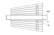
- a plurality of hybrid banknotes wound around the outer peripheral surface of the rotator by each tape becomes a so-called conical shape when viewed from a direction perpendicular to the axis, and the position of the hybrid banknotes stored in the rotator is There is a risk of shifting in the axial direction of the rotating body.
- the pair of left and right feeding rollers in the storing and feeding unit When the banknotes stored in the storage and feeding section are fed out from the storage and feeding section one by one, when the polymer film in the hybrid banknote contacts one of the feeding rollers and the piece of paper in the hybrid banknote contacts the other feeding roller Since the friction coefficients of the polymer film and the paper piece with respect to the feeding roller are different, the hybrid banknotes fed by the pair of feeding rollers may be skewed.
- the present invention has been made in consideration of such points, and appropriately stores special paper sheets such as hybrid banknotes in a storage unit or appropriately feeds special paper sheets from the storage unit.
- An object of the present invention is to provide a paper sheet processing machine and a paper sheet processing method.
- the paper sheet processing machine includes a transport unit that transports paper sheets, a storage unit that stores paper sheets sent from the transport unit, and a transport unit that is provided in the transport unit.
- a shift unit that shifts the sheets conveyed by the conveyance unit in the width direction according to the position of the specific member of the storage unit in the width direction that is a direction orthogonal to the direction.
- the paper sheet processing machine of the present invention further includes an identification unit that is provided in the conveyance unit and detects a predetermined characteristic portion of the paper sheet conveyed by the conveyance unit, and the shift unit is configured by the identification unit.
- the paper sheet may be shifted in the width direction based on the position in the width direction of the predetermined characteristic portion of the identified paper sheet.
- the storage unit has a belt-shaped winding member that winds the paper sheet on the outer peripheral surface of the sheet winding rotary body as the specific member, and should be stored in the storage unit.
- the shift unit shifts the paper sheet in the width direction so that the position of the predetermined feature portion of the paper sheet in the width direction at least partially overlaps the position of the winding member in the width direction of the storage unit. You may come to let me.
- the storage unit has a feeding member for feeding out the paper sheets stored in the storage unit in a stacked state from the storage unit as the specific member, and the paper to be stored in the storage unit
- the shift unit shifts the sheets in the width direction so that the position in the width direction of the predetermined characteristic portion of the leaves deviates from the position in the width direction of the feeding member of the storage unit. May be.
- identification unit and the shift unit may be connected by a linear conveyance path in the conveyance unit.
- the predetermined characteristic portion of the paper sheet may be a material portion other than the paper portion in the banknote.
- an identification unit that detects a predetermined characteristic portion of the paper sheet transported by the transport unit is located upstream of the shift unit in the transport direction of the paper sheet by the transport unit or A feature that is provided on the downstream side and detects the position of the predetermined feature portion of the paper sheet in the width direction on the opposite side of the transport unit from the side on which the identification unit is provided with respect to the shift unit.
- a partial detection unit is provided, and the shift amount in the width direction of the paper sheets by the shift unit is calculated based on the identification result by the identification unit and the detection result by the characteristic part detection unit. Good.
- the storage unit includes a paper sheet feeding mechanism that feeds the paper sheets stored in the storage unit to the transport unit, and a paper sheet by the paper sheet feeding mechanism.
- a storage space shift mechanism for shifting the storage space for the paper sheets in a direction orthogonal to the paper feeding direction may be provided.
- the paper sheet processing method of the present invention includes a step of transporting a paper sheet by a transport unit inside a paper sheet processing machine, and a storage unit in a width direction that is a direction orthogonal to the transport direction of the paper sheet. According to the position of the specific member, a step of shifting paper sheets conveyed by the conveyance unit in the width direction by a shift unit, and a paper sheet shifted in the width direction by the shift unit are stored in the storage unit. And a process of storing in the container.
- the paper sheet processing method of the present invention further includes a step of detecting a predetermined characteristic part of the paper sheet by an identification unit, and the shift unit is configured to detect the predetermined characteristic part of the paper sheet identified by the identification unit.
- the paper sheets may be shifted in the width direction based on the position in the width direction.
- the predetermined characteristic part of the paper sheet may be a material part other than the paper part in the banknote.
- FIG. 1 It is a schematic block diagram which shows an example of a structure of the banknote processing machine by embodiment of this invention. It is a functional block diagram which shows the structure of the control system of the banknote processing machine shown in FIG. It is explanatory drawing which shows the structure of the hybrid banknote processed by the banknote processing machine shown in FIG. It is a side view which shows the structure of the temporary storage part in the banknote processing machine shown in FIG. 1, Comprising: It is a figure which shows a state when the banknote is not wound up by the drum. It is a side view which shows the structure of the temporary storage part in the banknote processing machine shown in FIG. 1, Comprising: It is a figure which shows the maximum winding state in which the winding amount of the tape and banknote to a drum becomes the maximum.
- FIG. 1 It is a perspective view which shows each structural member of the drum vicinity in the temporary storage part shown in FIG. 4 and FIG. It is a top view which shows the structure of the shift part in the banknote processing machine shown in FIG. It is a side view of the shift part shown in FIG. It is a perspective view of the shift part shown in FIG. 7 and FIG.
- the banknotes are transferred by the shift unit shown in FIGS. 7 to 9 so that the position in the width direction of the polymer film portion of the hybrid banknote is at least partially overlapped with the position in the tape width direction of the temporary storage unit.
- FIG. 14 (A) is a side view which shows a structure when the storage space of a banknote is shifted to the left by the storage space shift mechanism in the banknote storage shown in FIG. 14 (a), and (b) is a storage of banknotes. It is a top view which shows the structure of a banknote feeding mechanism when space is shifted leftward by the storage space shift mechanism. In a prior art, it is a figure which shows a state when the some hybrid banknote wound by the outer peripheral surface of the rotary body with each tape became cone shape.
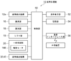
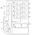
- FIG. 1 is a schematic configuration diagram showing an example of the configuration of the banknote handling machine according to the present embodiment
- FIG. 2 is a functional block diagram showing the configuration of the control system of the banknote handling machine shown in FIG.
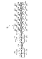
- FIG. 3 is explanatory drawing of the hybrid banknote processed with the banknote processing machine shown in FIG. 4
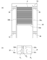
- FIG. 5 are side views showing the configuration of the temporary storage unit in the banknote handling machine shown in FIG. 1, and
- FIG. 6 shows each of the vicinity of the drum in the temporary storage unit shown in FIG. 4 and FIG. It is a perspective view which shows a structural member.
- FIG. 7 to 9 are a top view, a side view, and a perspective view, respectively, showing the configuration of the shift unit in the banknote handling machine shown in FIG.
- FIG. 10 and FIG. 11 are explanatory diagrams showing operations when the bill is shifted by the shift unit shown in FIGS.
- the banknote handling machine 10 includes a substantially rectangular parallelepiped casing 11, an insertion portion 12 for inserting banknotes from the outside of the casing 11, A dispensing unit 14 for dispensing bills from the inside to the outside is provided.
- the conveyance part 16 which conveys a banknote one by one is provided.
- the input unit 12 includes a hopper or the like on which a plurality of banknotes are stacked in a stacked state by an operator. The input unit 12 feeds the stacked banknotes one by one into the housing 11 and conveys the banknotes.
- a bill feeding mechanism 12 a to be sent to 16 is provided.
- banknotes placed on the insertion unit 12 are fed one by one into the housing 11 by the bill feeding mechanism 12 a and sent to the transport unit 16, and then the housing 11 is transported by the transport unit 16.
- Each sheet is conveyed one by one.
- a stack of banknotes is inserted into the input unit 12 along the short direction, and the transport unit 16 transports the banknotes along the short direction.
- an identification unit 18 is provided in the conveyance unit 16, and the identification unit 18 identifies the denomination, authenticity, front / back, correct / incorrect, new / old, conveyance state, and the like of the banknotes conveyed by the conveyance unit 16. To be done.
- the transport unit 16 is provided with a shift unit 19, and the banknotes transported by the transport unit 16 by the shift unit 19 are orthogonal to the transport direction by the transport unit 16 (that is, by the transport unit 16. The position is shifted along the width direction of the bills being conveyed.
- the identification unit 18 and the shift unit 19 are connected by a linear conveyance path in the conveyance unit 16. Details of the configuration of the shift unit 19 will be described later.
- a temporary storage unit 20 is connected to the transport unit 16, and the banknotes identified by the identification unit 18 are sent to the temporary storage unit 20 by the transport unit 16 and temporarily stored in the temporary storage unit 20. It has come to be. Details of the configuration of the temporary holding unit 20 will be described later.
- each banknote storage 30 is provided in parallel within the housing 11 of the banknote handling machine 10, and each banknote storage 30 is respectively It is connected to the transport unit 16.
- a plurality of banknotes are stacked in each banknote storage 30 in a stacked state.
- banknotes are stored in each banknote storage 30 for each denomination.
- the banknotes temporarily held in the temporary storage unit 20 are fed out from the temporary storage unit 20 to the transport unit 16 and are transported by the transport unit 16.
- Each denomination is sent to each banknote storage 30.
- Each banknote storage 30 is provided with a banknote feeding mechanism 32 for feeding banknotes stored in the banknote storage 30 one by one to the transport unit 16.
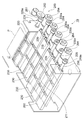
- a bill storage cassette 40 is detachably mounted in the housing 11 of the bill processing machine 10.
- a plurality of banknotes are stacked on the banknote storage cassette 40 in a stacked state.
- the bill is sent from the transport unit 16 to the bill storage cassette 40.
- the operator can collect the banknotes from the banknote processor 10 together with the banknote storage cassette 40 by taking out the banknote storage cassette 40 from the housing 11.
- the banknote storage cassette 40 has a banknote feeding mechanism for feeding the banknotes stored in the banknote storage cassette 40 one by one to the transport unit 16 when the banknote storage cassette 40 is mounted in the housing 11. 42 is provided. With such a configuration, it is possible to replenish banknotes from the banknote storage cassette 40 to each banknote storage 30 by mounting the banknote storage cassette 40 storing banknotes in the housing 11.
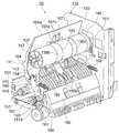
- FIG. 4 is a side view illustrating the configuration of the temporary storage unit 20 in the banknote handling machine 10 illustrated in FIG. 1, and is a diagram illustrating a state when no banknote is wound on the drum 137.
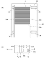
- These are side views which show the structure of the temporary storage part 20 in the banknote processing machine 10 shown in FIG. 1, Comprising: It is a figure which shows the maximum winding state in which the winding amount of the tape 136 and banknote to the drum 137 becomes the maximum.
- FIG. 6 is a perspective view showing components in the vicinity of the drum 137 in the temporary storage unit 20 shown in FIGS. 4 and 5.
- the temporary storage part 20 functions as a banknote accommodation paying-out apparatus which can draw
- a bill before being sent to the temporary storage unit 20 and a banknote after being fed out from the temporary storage unit 20 are indicated by a reference symbol P.
- the temporary storage unit 20 includes a rectangular parallelepiped frame 132 including side plates 130 on both sides and a plurality of connecting members 131 that connect these side plates 130.
- One surface of the frame 132 is formed as a passage surface that constitutes a part of the conveyance unit 16 so as to face the conveyance unit 16, and a banknote (see FIG. 4) is formed on the passage surface with respect to the conveyance unit 16.
- An entrance / exit 135 for entering and exiting) is formed.
- a cylindrical drum 137 to which one end of the tape 136 is attached, a disk-shaped reel 138 to which the other end of the tape 136 is attached, and banknotes conveyed by the conveying unit 16 are entered and exited 135.
- a swingable guide body 141 and the like for guiding the tape 136 and the bill are disposed.
- the drum 137 is disposed in a substantially central region of the side plate 130, the reel 138 is disposed side by side at the entrance / exit 135 and the side of the transport mechanism 140, and the guide body 141 is disposed so as to be swingable between the drum 137 and the reel 138. ing.
- the transport mechanism 140 forms a fixed passage 142 that extends along the direction from the entrance / exit 135 toward the drum 137 and connects the entrance / exit 135 to the guide body 141.
- a tape 136 and a guide passage 143 for guiding bills are formed in the guide body 141.
- the guide passage 143 is configured as a swing passage 144 because the guide body 141 swings.
- the banknote sent from the transport unit 16 is temporarily stored in the temporary storage unit 20
- the banknote is taken in from the entrance / exit 135, transported to the drum 137 through the transport mechanism 140 and the guide body 141, and the banknote together with the tape 136. Is wound around a drum 137 and banknotes are stored in the drum 137.
- the drum 137 is wound by winding the tape 136 around the reel 138, that is, by rewinding the tape 136 from the drum 137.
- the bill is rewound onto the guide body 141 and fed out to the entrance / exit 135 through the transport mechanism 140.
- the width of the tape 136 is smaller than the width that intersects the banknote transport direction, that is, the width in the longitudinal direction of the banknote (hereinafter simply referred to as the banknote width).
- the banknote width As shown in FIG. 6, two tapes 136 are used and are arranged in parallel at intervals in the axial direction of the drum 137 and the reel 138. Therefore, the two tapes 136 are wound around the drum 137 in a state where two positions in the banknote width direction are pressed, and in the winding state, the width direction of the banknotes is between the two tapes 136 and from both sides of the two tapes 136. The central part and the both side parts of each are exposed.
- the tape 136 is formed of, for example, a transparent film material having a light transmittance of a predetermined amount or more, and the end region attached to the drum 137 has a predetermined amount or more for detecting a rewind limit from the drum 137.
- an opaque portion that does not have optical transparency is provided.
- the other end region attached to the reel 138 is provided with, for example, an opaque portion that does not have a light transmittance of a predetermined amount or more for detecting a winding limit around the drum 137.
- These opaque portions are formed of, for example, opaque seals and are attached to the two tapes 136, respectively.
- the surface of the tape 136 that becomes the inner diameter side when wound around the drum 137 and the reel 138 is called a first surface 136a, and the surface that becomes the outer diameter side is called a second surface 136b.
- the drum 137 has a cylindrical shape larger in diameter than the reel 138, and can rotate in a circumferential direction at a fixed position around a drum shaft 147 rotatably supported on both side plates 130.
- a drive motor 148 that rotates the drum 137 is disposed inside the drum 137, and this drive motor 148 is attached to the side plate 130 on one side.
- the reel 138 is attached to a reel shaft 149 rotatably supported on both side plates 130 via a torque limiter (not shown), and can be rotated in a circumferential direction at a fixed position around the reel shaft 149. Yes.
- a transmission mechanism (not shown) that transmits a rotational driving force from the drum 137 to the reel 138 is disposed outside the side plate 130 on one side, and a rotation amount detector 151 that detects the rotation amount of the drum 137. (See FIG. 6) is provided.
- the transmission mechanism transmits a rotational driving force to the reel shaft 149 when rotating the reel 138 in the winding direction of the tape 136, and transmits a rotational driving force to the reel shaft 149 when rotating the reel 138 in the rewinding direction of the tape 136. Do not have a one-way clutch.
- the reel 138 When the bill sent from the transport unit 16 is temporarily stored in the temporary storage unit 20, when the drum 137 is rotated in the winding direction of the tape 136 by the drive motor 148, the reel 138 is rotated by the one-way clutch. The driving force is not transmitted, and the tape 136 wound around the drum 137 is pulled out from the reel 138 against the torque limiter. Further, when the banknote temporarily held in the temporary storage unit 20 is fed out to the transport unit 16, the drive motor 148 drives the drum 137 to rotate in a rewind direction that is opposite to the winding direction of the tape 136. At this time, the rotational driving force is transmitted to the reel 138 via the one-way clutch, and the reel 138 rotates in the winding direction of the tape 136.
- the reel 138 by transmitting the rotational driving force to the reel 138 via the torque limiter so that the speed at which the tape 136 is wound around the reel 138 is always higher than the speed at which the tape 136 is rewound from the drum 137, the reel 138 The tape 136 can be wound up without slack.
- the branch lever 139 is swingable with the lever shaft 153 as a fulcrum, and is advanced and retracted with respect to the transport unit 16 by driving a stepping motor or a solenoid. Then, the branch lever 139 advances into the transport unit 16, so that the banknotes transported by the transport unit 16 are taken into the entrance / exit 135 and the banknotes are fed out from the entrance / exit 135 to the transport unit 16, while the branch lever 139 is By retreating from 16, the passage of banknotes transported in the transport unit 16 is allowed.
- the transport mechanism 140 stretches the belts 155a and 155b and the belts 155a and 155b so as to be rotatable along both sides of the fixed passage 142 and the swing passage 144, and contacts the surfaces of the belts 155a and 155b with each other.
- a plurality of pulleys 156a, 156b, 157a, 157b, and 158 are provided.
- the pulleys 156a, 156b, 157a, 157b, 158 are pivotally supported on both sides of the entrance / exit 135 so as to be rotatable at fixed positions with respect to the side plates 130 on both sides.
- the pulleys 157a and 157b disposed on the swing passage 144 side are rotatably supported by the guide body 141 and swing together with the guide body 141.
- the pulley 158 disposed in the middle portion of the one belt 155a is pivotally supported at a fixed position with respect to the side plates 130 on both sides at a position closer to the drum 137 than the entrance / exit 135.
- the pulley shaft 159 of the pulley 158 serves as a fulcrum 141a of the swinging guide body 141.
- a portion from the entrance 135 to the vicinity of the fulcrum 141 a is formed as a fixed passage 142
- a portion from the vicinity of the fulcrum 141 a to the inside of the guide body 141 is formed as a swing passage 144.
- the fixed passage 142 is provided with a fixed guide 160 for guiding bills.
- a gear 161 (see FIG. 6) is attached to the shaft of the pulley 156b.
- the gear 161 meshes with a gear of a driving mechanism disposed in the main body portion of the banknote handling machine 10, and the belt 155b passes through the gear 161 from the driving mechanism. Rotational driving force is transmitted to. Further, the rotational driving force is transmitted from the gear 161 to the pulley shaft 159 of the pulley 158 via the transmission means 162, and thereby the rotational driving force is transmitted to the belt 155a.
- the guide body 141 includes a first guide member 164 and a second guide member 165, and both sides of the first guide member 164 and the second guide member 165 are support members 166 (FIG. 6).
- the support members 166 on both sides of these are integrally supported by the pulley shaft 159 so as to be swingable. That is, as described above, the guide body 141 is supported so as to be swingable about the fulcrum 141a.
- the inner surface where the first guide member 164 and the second guide member 165 face each other is used as a passage surface, and a guide passage 143 for guiding the tape 136 and the bill is formed between these passage surfaces. That is, a swing passage 144 that swings around the fulcrum 141a is formed between these passage surfaces.
- the shape of the guide body 141 that is, the shape of the first guide member 164 and the second guide member 165, and the shape of the guide passage 143 and the swing passage 144 are the tape 136 to the drum 137 and the bill. Is formed in a curved shape along the maximum outer diameter portion (indicated by reference numeral 137p in FIG. 5) in the maximum winding state in which the winding amount of the coil is maximum.
- the extension part 164a extended longer than the tip side opposite to the fulcrum 141a of the second guide member 165 is formed on the tip side opposite to the fulcrum 141a of the first guide member 164.
- the extension portion 164a of the first guide member 164 has two pieces on the downstream side in the winding direction from the contact point of the tape 136 wound on the drum 137 (indicated by reference numeral S in FIGS. 4 and 5).
- a contact roller 167 that directly contacts the drum 137 or the banknote wound around the drum 137 through the tape 136 is disposed.
- the contact roller 167 includes a first contact roller 167a and a second contact roller 167b.
- the first contact roller 167a is used for the banknote wound around the drum 137 when the tape 136 and the banknote wound on the drum 137 are smaller than the predetermined outer diameter in the winding state.
- the second contact roller 167b is used for the banknote wound on the drum 137 when the outer diameter of the tape 136 and the banknote wound on the drum 137 is larger than the predetermined outer diameter when the winding amount is larger than the predetermined amount.
- the first contact roller 167a and the second contact roller 167b are also in contact with the downstream side in the winding direction with respect to the contact point S of the tape 136 wound around the drum 137.
- a spring 168 as an urging means for urging the guide body 141 toward the drum 137 is stretched. Due to the urging of the spring 168, the contact roller 167 is always pressed against the drum 137 side.
- the guide body 141 is configured to swing around the fulcrum 141a in accordance with each operation of winding and rewinding the tape 136 and the bill on the drum 137.
- the peeling claw 169 that peels off the banknote to be rewound together with the tape 136 from the drum 137 from the outer peripheral surface of the drum 137 and sends it to the swing passage 144. It is arranged so that it can swing.
- the peeling claw 169 swings toward the drum 137 and is biased by a spring or the like so that the tip of the peeling claw 169 always contacts the tape 136.
- both sides of the second guide member 165 on the front end side are obliquely cut off on both sides on the front end side of the second guide member 165, and both side portions of the banknote to be rewound from the drum 137 are provided.
- a guide portion 170 is formed to guide the swing passage 144 so as to easily enter the swing passage 144.
- pulleys 157a and 157b of the transport mechanism 140 are rotatably supported by the first guide member 164 and the second guide member 165, respectively.
- the first guide member 164 is rotatably supported by a guide roller 172 that guides the tape 136 between the reel 138 and the swing path 144, and between the reel 138 and the guide roller 172.
- a tape guide 173 for guiding the tape 136 is attached.
- the first guide member 164 detects the unwinding limit from the drum 137 and the winding limit to the drum 137 by detecting opaque portions provided in one end region and the other end region of the tape 136, respectively.
- a tape end detector (not shown) is arranged. This tape end detection unit is arranged corresponding to each tape 136.
- a guide roller 172 and a swing path 144 are provided near the tip of the second guide member 165 and near the end of the swing path 144 (guide path 143) facing the drum 137.
- the guide mechanism 184 that guides the tape 136 and the banknotes is provided therebetween.
- the guide mechanisms 184 are individually arranged corresponding to the positions of the two tapes 136.
- each guide mechanism 184 corresponding to each of the two tapes 136 is disposed on a driving roller 185 and a transmission roller (not shown) disposed on the first guide member 164 and on the second guide member 165.
- a guide roller 188 is provided therebetween.
- the driving force is transmitted from the tape 136 that moves to the driving roller 185 that contacts the second surface 136b of the tape 136, and rotates together with the driving roller 185.
- the driving force is transmitted from the transmission roller to the guide roller 188.
- claw 169 is provided so that rotation and attachment / detachment are possible.
- the guide body 141 is provided with a banknote detector 195 that detects the banknote in a region where the banknote is conveyed together with the tape 136 in the swing passage 144.
- This banknote detection part 195 is comprised from the optical sensor etc., and a banknote is detected because sensor light is light-shielded at the time of passage of a banknote.
- FIGS. 7 is a top view showing the configuration of the shift unit 19 in the banknote handling machine 10 shown in FIG. 1
- FIG. 8 is a side view of the shift unit 19 shown in FIG. 7
- FIG. 9 is a perspective view of the shift unit 19 shown in FIG. 8.
- the banknote shifted by the shift part 19 is shown with the reference code P.
- FIG. 7 and FIG.9 the banknote shifted by the shift part 19 is shown with the reference code P.
- the shift unit 19 is fixed in position, and slides along the first fixed conveyance unit 220 that conveys paper sheets along the conveyance path 211 and the width direction (vertical direction in FIG. 7) of the conveyance path 211.
- a plurality of (for example, four) slide transport mechanisms 230 that respectively transport the banknotes delivered from the first fixed transport unit 220 and their positions are fixed.
- a second fixed conveyance unit 250 that conveys the delivered banknote.
- an upstream side conveyance unit 212 is provided on the upstream side of the first fixed conveyance unit 220 in the bill conveyance direction.
- the banknotes are conveyed one by one from the left side to the right side along the conveyance path 211 extending in the left-right direction in FIG. 7 in the shift unit 19. At this time, the bills are conveyed along the short direction.
- the upstream conveyance unit 212 includes an upper conveyance belt 214 stretched by a plurality of upper rollers 215 and a lower conveyance belt 216 stretched by a plurality of lower rollers 217. It is composed of In FIG. 7, the configuration of the lower conveyance belt 216 when the upper conveyance belt 214 and the upper roller 215 are removed from the shift unit 19 is illustrated. Here, a drive motor is attached to one lower roller 217 among the plurality of lower rollers 217, and the lower roller 217 is rotated by this drive motor, so that the lower conveyor belt 216 has the configuration shown in FIG. It is designed to circulate in the clockwise direction at. Further, the upper conveyor belt 214 also rotates with the lower conveyor belt 216.
- the lower conveyor belt 216 When the lower conveyor belt 216 is circulated in the clockwise direction in FIG. It can be circularly moved in the clockwise direction. And in the upstream conveyance part 212, a banknote is conveyed rightward from the left side in FIG.7 and FIG.8 in the state clamped between the upper side conveyance belt 214 and the lower side conveyance belt 216.
- FIG. 7 the lower conveyance belt 216 is arranged in a pair of left and right along the width direction (vertical direction in FIG. 7) in the conveyance path 211, and corresponds to the lower conveyance belt 216.
- the upper conveyor belt 214 is also arranged in a pair of left and right along the width direction in the conveyance path 211.
- the first fixed transport unit 220 is composed of an upper guide unit 222 and a lower guide unit 224 that are arranged to be spaced apart from each other in a vertical direction with a slight distance. Between the upper guide part 222 and the lower guide part 224, a transport path 211 through which bills are transported is formed.
- the lower guide portion 224 is provided with a pair of drive rollers 226 along the width direction in the transport path 211, and the upper guide portion 222 has each drive roller A pair of driven rollers 228 are provided so as to face the H.226 along the width direction in the conveyance path 211.
- FIG. 7 illustrates the configuration of the lower guide unit 224 and the driving roller 226 when the upper guide unit 222 and the driven roller 228 are removed from the first fixed conveyance unit 220.
- a high friction member such as rubber is disposed on the outer peripheral surface of the driving roller 226, and this driving roller 226 is illustrated by a roller driving unit 260 described later via a driving shaft 229. 8 is rotated in the clockwise direction.
- a metal member is disposed on the outer peripheral surface of the driven roller 228, and the driven roller 228 is provided in the upper guide portion 222 so as to abut on the drive roller 226 and follow the drive roller 226.
- a banknote is sent to the nip part formed between the drive roller 226 and the driven roller 228, and the said banknote is conveyed now in the right direction in FIG. 7 and FIG. 8 along the conveyance path 211. Yes.
- the second fixed transport unit 250 is composed of an upper guide unit 252 and a lower guide unit 254 arranged so as to be spaced apart from each other in a vertical direction at a slight distance.
- a conveyance path 211 through which bills are conveyed is formed between the upper guide portion 252 and the lower guide portion 254.
- the lower guide portion 254 is provided with a pair of left and right drive rollers 256 along the width direction of the transport path 211, and the upper guide portion 252 has a drive roller.
- the driven rollers 258 are provided in a pair of left and right along the width direction in the conveyance path 211 so as to face the 256.
- FIG. 7 illustrates the configuration of the lower guide unit 254 and the driving roller 256 when the upper guide unit 252 and the driven roller 258 are removed from the second fixed conveyance unit 250.
- a high friction member such as rubber is disposed on the outer peripheral surface of the driving roller 256, and this driving roller 256 is illustrated by a roller driving unit 260 described later via a driving shaft 259. 8 is rotated in the clockwise direction.
- a metal member is disposed on the outer peripheral surface of the driven roller 258, and the driven roller 258 is provided in the upper guide portion 252 so as to contact the drive roller 256 and rotate with the drive roller 256.
- a banknote is sent to the nip part formed between the drive roller 256 and the driven roller 258, The said banknote is made to be conveyed rightward in FIG. 7 and FIG. 8 along the conveyance path 211. Yes.
- a plurality (for example, four) of slide transport mechanisms 230 are arranged in series along the banknote transport direction.
- Each slide type transport mechanism 230 is slidable along the width direction of the transport path 211 (vertical direction in FIG. 7) independently of the other slide type transport mechanisms 230. Accordingly, regardless of the position of the banknote in the width direction of the transport path 211 in the first fixed transport unit 220 on the upstream side of each slide transport mechanism 230, the bill is transported by each slide transport mechanism 230. By moving along the width direction of 211, the paper sheet sent from each sliding transport mechanism 230 to the second fixed transport unit 250 is brought to a predetermined position in the width direction of the transport path 211. It will be a thing.
- each sliding transport mechanism 230 includes an upper guide portion 232 and a lower guide portion 234 that are arranged so as to be spaced apart from each other in a vertical direction at a slight distance. Between the guide part 232 and the lower side guide part 234, the conveyance path 211 in which a banknote is conveyed is formed. The upper guide part 232 and the lower guide part 234 are connected to each other, and the upper guide part 232 and the lower guide part 234 can be integrally slid along the width direction in the transport path 211. In addition, as shown in FIG.
- the lower guide portion 234 is provided with a pair of drive rollers 236 along the width direction in the conveyance path 211, and the upper guide portion 232 has each drive roller
- the driven rollers 238 are provided in a pair of left and right along the width direction in the transport path 211 so as to oppose the 236.
- FIG. 7 illustrates the configuration of the lower guide unit 234 and the drive roller 236 when the upper guide unit 232 and the driven roller 238 are removed from each slide type transport mechanism 230.
- each sliding transport mechanism 230 a high friction member such as rubber is disposed on the outer peripheral surface of the drive roller 236, and this drive roller 236 is driven by a roller drive unit 260 (described later) via a drive shaft 239. Can be rotated in the clockwise direction. Further, a metal member is disposed on the outer peripheral surface of the driven roller 238, and the driven roller 238 is provided in the upper guide portion 232 so as to abut on the drive roller 236 and follow the drive roller 236. And a banknote is sent to the nip part formed between the drive roller 236 and the driven roller 238, The said banknote comes to be conveyed rightward in FIG. 7 and FIG. 8 along the conveyance path 211. Yes.
- the driving roller 226 of the first fixed conveyance unit 220, the driving roller 236 of each sliding conveyance mechanism 230, and the driving roller 256 of the second fixed conveyance unit 250 are a single driving system. It is driven by a roller driving unit 260. Details of the configuration of the roller driving unit 260 will be described with reference to FIGS. 7 and 9. As shown in FIGS. 7 and 9, the drive shaft 229 of the drive roller 226 of the first fixed transport unit 220, the drive shaft 239 of the drive roller 236 of each sliding transport mechanism 230, and the drive of the second fixed transport unit 250.
- Gears 229a, 239a, and 259a are provided at the respective tip portions of the drive shaft 259 of the roller 256, and drive gears 264 are provided between the gears 229a, 239a, and 259a, respectively.
- a drive gear 262 is arranged so as to mesh with a gear 229 a provided at the tip of the drive shaft 229 of the drive roller 226 of the first fixed transport unit 220, and the drive gear 262 includes a drive gear. 261 are arranged to mesh with each other. Then, when the drive gear 261 is rotated by a drive motor such as a stepping motor (not shown), the gear 229a is rotated via the drive gear 262, and this rotational driving force is transmitted to each gear via the drive gear 264. 239a and gear 259a. In this way, the drive shafts 229, 239, and 259 rotate integrally, and the drive rollers 226, 236, and 256 also rotate integrally.
- each drive gear 264 extends along the width direction of the transport path 211 (that is, the longitudinal direction of each drive shaft 239).
- the upper guide portion 232 and the lower guide portion 234 of each sliding transport mechanism 230 slide along the width direction of the transport path 211, and the drive shaft 239 of each drive roller 236 also extends along the width direction of the transport path 211.
- the gears 239a move, the connection between the gears 239a and the drive gears 264 is not released.
- the drive rollers 226, 236, and 256 can be integrally rotated by the roller drive unit 260. become.
- an entrance-side paper sheet detection sensor 270 is installed on the upstream side of the first fixed transport unit 220 in the banknote transport direction, and the banknote transport direction.
- An exit side paper sheet detection sensor (not shown) is installed on the downstream side of the second fixed conveyance unit 250 in FIG.
- the entrance-side paper sheet detection sensor 270 has a width direction length, a position in the width direction of the transport path 211, and a skew angle (skew) of the banknotes transported by the upstream transport unit 212 along the transport path 211. Etc.) are detected.
- the banknote detection information detected by the entrance-side paper sheet detection sensor 270 is sent to the control unit 50 described later.
- the exit-side paper sheet detection sensor has a width direction length and a width direction of the transport path 211 for the banknotes that are transported after being brought to a predetermined position in the width direction of the transport path 211 by each sliding transport mechanism 230.
- the position, the skew angle (skew amount), and the like are detected.
- the detection information of the banknote detected by the exit side paper sheet detection sensor is also sent to the control unit 50 which will be described later.
- the control unit 50 detects the paper sheet sent from the exit side paper sheet detection sensor. Based on the detection information, it is determined whether or not the bill has been accurately brought to a predetermined position in the width direction of the transport path 211 by each sliding transport mechanism 230.
- the upstream side of the first fixed transport unit 220 in the banknote transport direction and the downstream side of the entrance side paper sheet detection sensor 270 is located at the entrance side.
- a conveyance timing detection sensor 274 is installed.
- an exit-side transport timing detection sensor (not shown) is installed at a position downstream of the second fixed transport unit 250 in the banknote transport direction and upstream of the exit-side paper sheet detection sensor.
- the entrance-side transport timing detection sensor 274 is configured to detect the timing of the banknote immediately before being sent to the first fixed transport unit 220, and the exit-side transport timing detection sensor is controlled by each slide transport mechanism 230.
- the timing of the banknote sent from the 2nd fixed conveyance part 250 after the position in the width direction of the conveyance path 211 was brought close to the predetermined position is detected.
- the banknote detection information by the entrance-side transport timing detection sensor 274 and the exit-side transport timing detection sensor is sent to the control unit 50 described later.
- the entrance-side paper sheet detection sensor 270 detects the width direction length of the banknote, the position in the width direction of the transport path 211, the skew angle (skew amount), and the like. Information detected by the entrance-side paper sheet detection sensor 270 is sent to the control unit 50 described later.
- the control unit 50 detects the position of the banknote in the width direction of the transport path 211 before being sent to each slide transport mechanism 230 detected by the entrance-side paper sheet detection sensor 270, and the transport path 211 set in advance.
- each sliding transport mechanism 230 The amount of movement of each sliding transport mechanism 230 is calculated based on the predetermined position of the banknote in the width direction. Thereafter, the banknote is transported along the transport path 211 by the upstream transport unit 212 and delivered to the first fixed transport unit 220. Then, the banknotes are transferred from the first fixed transport unit 220 to each slide transport mechanism 230, and are sequentially transported in the right direction in FIGS. 7 and 8 by each slide transport mechanism 230, and then each slide transport mechanism. It is transferred from the transport mechanism 230 to the second fixed transport unit 250.
- the bills are sequentially conveyed in the right direction in FIG. 7 and FIG.
- each slide type transport mechanism 230 the upper guide portion 232 and the lower guide portion 234 of each slide type transport mechanism 230 are connected to the transport path 211. Slide along the width direction. Therefore, regardless of the position of the banknote in the width direction of the transport path 211 in the first fixed transport section 220 on the upstream side, the bills are moved along the width direction of the transport path 211 by each slide transport mechanism 230. By doing so, the banknotes sent from the respective slide type transport mechanisms 230 to the second fixed transport unit 250 are such that the position in the width direction of the transport path 211 is brought to a predetermined position.
- the banknote handling machine 10 of the present embodiment is provided with a control unit 50 that controls each component of the banknote handling machine 10. More specifically, the control unit 50 includes a bill feeding mechanism 12 a provided in the insertion unit 12, a transport unit 16, an identification unit 18, a shift unit 19, and a temporary storage unit 20 (specifically, the temporary storage unit 20.
- the drive motor 148), the banknote feeding mechanism 32 provided in each banknote storage 30, the banknote feeding mechanism 42 provided in the banknote storage cassette 40 mounted in the housing 11 are connected to be communicable with each other.
- the signal which concerns on the identification result of the banknote by the identification part 18 is sent to the control part 50, the control part 50 controls operation
- an operation display unit 52 is connected to the control unit 50 so as to communicate with each other.
- the operation display unit 52 includes, for example, a touch panel provided on the upper surface of the housing 11, and is stored in the banknote storage machine 30 and the banknote storage cassette 40, such as banknote depositing processing in the banknote processing machine 10.
- Information relating to the banknote amount is displayed on the operation display unit 52.
- the operation display part 52 may be configured to display information relating to the storage state of banknotes in the temporary storage unit 20, each banknote storage 30, the banknote storage cassette 40, or the like.
- the operation display unit 52 displays information as to whether or not a plurality of hybrid banknotes wound around the outer peripheral surface of the drum 137 by the tapes 136 in the temporary storage unit 20 have a so-called conical shape. It may come to be. Further, as will be described later, instead of providing a banknote storage 30 in which a plurality of banknotes are stacked in a stacked state as a storage unit for storing banknotes, the banknotes are wound around the outer peripheral surface of the drum with a tape. In the case where each storing and feeding part 60 (see FIG.
- the storage unit 54 stores information on processing histories such as banknote deposit processing in the banknote handling machine 10 and information on banknotes stored in each banknote storage 30 and banknote storage cassette 40. Yes.
- the storage unit 54 may store information related to the storage state of banknotes in the temporary storage unit 20, each banknote storage 30, the banknote storage cassette 40, and the like.
- the control unit 50 can transmit and receive signals to and from an external device (specifically, for example, a host terminal) provided separately from the banknote handling machine 10 according to the present embodiment via the communication interface unit 56. It can be done.
- control part 50 is provided in the housing
- the temporary storage part 20 as a banknote accommodation delivery apparatus.
- a control unit that controls each component of the temporary storage unit 20 may be installed in the temporary storage unit 20.
- the banknote processing machine 10 of this Embodiment can process the hybrid banknote which combined paper and a polymer film in addition to the normal banknote comprised only from paper. .
- the structure of such a hybrid banknote is demonstrated using FIG.
- hybrid bill is formed by sandwiching a polymer film portion P 2 extending linearly along the widthwise direction of the bill by a pair of paper portion P 1 Has been.
- hybrid banknotes are also considered to be normal banknotes. Therefore, when the banknotes are identified by the identification unit 18, the hybrid banknotes as shown in FIG. 3 are identified.
- the controller 50 determines that such a hybrid banknote is a normal banknote.
- the polymer film portion P 2 in such a hybrid bill stronger stiffness than paper portions P 1,
- the thickness of the polymeric film portion P 2 is larger than the thickness of the paper portion P 1.
- a hybrid bill to be held in the escrow unit 20 the position in the width direction of the polymer film portion P 2 of the hybrid bills in the width direction of the tape 136 of the escrow unit 20
- the hybrid banknote before being sent to the temporary storage unit 20 is shifted in the width direction of the hybrid banknote by the shift unit 19 so that at least a part of the position overlaps.
- the hybrid banknotes before being sent to each banknote storage 30 or banknote storage cassette 40 are shifted by the shift unit 19 so as to be shifted from the positions in the width direction of the pair of feeding rollers of the banknote feeding mechanisms 32 and 42 of the cassette 40. It is designed to shift in the width direction.
- each banknote storage 30 or banknote storage cassette 40 feeds out the banknotes stored in each banknote storage 30 or banknote storage cassette 40 by each banknote feeding mechanism 32 or 42, a pair of left and right feeding rollers. bill to be fed to the transport unit 16 for paper part P 1 comes into contact respectively so that it is possible to prevent the skewed in the hybrid bills in. Details of such technical matters will also be described later.
- the operator can manually remove the reject banknotes accumulated in the dispensing unit 14 from the housing 11 and place it on the insertion unit 12 again.
- the banknote identified as a normal banknote by the identification unit 18 is sent from the transport unit 16 to the temporary storage unit 20 after passing through the shift unit 19, and temporarily stored in the temporary storage unit 20.
- the identifying unit 18 bill a hybrid bill as shown in FIG.
- FIG. 10 shows the operation of the hybrid banknote after it is identified by the identification unit 18 and then sent to the temporary storage unit 20 through the shift unit 19.
- the conveyance direction of the hybrid banknote by the conveyance unit 16 is the right direction.
- the same position as the position in the width direction of each tape 136 of the temporary storage unit 20 in the transport path of the transport unit 16 is indicated by reference numeral L1.
- the identification unit 18 detects the position in the width direction of the hybrid banknote conveyed by the conveyance unit 16.
- the shift unit 19 based on the position in the width direction of the polymer film portion P 2 of the hybrid banknote recognized by the recognition unit 18, shifts the bill in the widthwise direction.
- the hybrid banknote immediately after being identified by the identification unit 18 is the position in the width direction of the polymer film portion P 2. Is deviated from the position of the tape 136 in the width direction of each tape 136 (see the leftmost hybrid banknote in FIG. 10).
- the hybrid bill is shifted in the width direction by the shift unit 19 (specifically, the hybrid bill is shifted so as to move upward in FIG. 10), and after passing through the shift unit 19.
- the hybrid bill to be held in the escrow unit 20 the position in the width direction of the polymer film portion P 2 of the hybrid bill position in the width direction of the tape 136 of the escrow unit 20
- the hybrid banknote before being sent to the temporary storage unit 20 is shifted in the width direction of the hybrid banknote by the shift unit 19 so that at least a part thereof overlaps.
- This makes it possible to fasten directly on the outer peripheral surface of the drum 137 by the lower side of the tape 136 in the out view 10 of a hybrid bill polymeric film portion P 2 a pair of tape 136 in the escrow unit 20. For this reason, a hybrid banknote can be appropriately accommodated in the drum 137 of the temporary storage unit 20.
- the banknote drawn out from the temporary storage part 20 is a hybrid banknote as shown in FIG. when the can, so that the position in the width direction of the polymer film portion P 2 of the hybrid banknote is displaced from the position in the width direction of the pair of feeding rollers 32a of the banknote feeding mechanism 32 of the bill storage 30 (see FIG. 11)
- the hybrid banknote before being sent to each banknote storage 30 is shifted in the width direction of the hybrid banknote by the shift unit 19. The operation of the shift unit 19 will be described with reference to FIG.
- FIG. 11 after the hybrid banknotes fed from the temporary storage unit 20 to the transport unit 16 are identified by the identification unit 18, the operations of the hybrid banknotes until the hybrid banknotes are sent to each banknote storage 30 through the shift unit 19. It is shown.
- the conveyance direction of the hybrid banknote by the conveyance part 16 is the right direction.
- the same position as the position in the width direction of each delivery roller 32a of the banknote feeding mechanism 32 of each banknote storage 30 in the conveyance path of the conveyance part 16 is shown by the reference symbol L2.
- the identification unit 18 detects the position in the width direction of the hybrid banknote fed from the temporary storage unit 20 to the transport unit 16.
- the shift unit 19 based on the position in the width direction of the polymer film portion P 2 of the hybrid banknote recognized by the recognition unit 18, shifts the bill in the widthwise direction.
- the hybrid banknote immediately after being identified by the identification unit 18 is the position in the width direction of the polymer film portion P 2.
- the hybrid bill is shifted in the width direction by the shift unit 19 (specifically, the hybrid bill is shifted so as to move downward in FIG. 11), and after passing through the shift unit 19.
- hybrid bill the position in the width direction of the polymer film portion P 2 is so deviated from the position in the width direction of the feeding rollers 32a of the banknote feeding mechanism 32 provided in each bill storage 30 (shift in FIG. 11 parts (See the hybrid bill located on the right side of 19).
- the hybrid bill to be stored in each bill storage 30, the width of each feeding roller 32a of the hybrid bill polymer film portion P 2 of the width position in the direction of the bill feeding mechanism 32 The hybrid banknote before being sent to each banknote storage 30 is shifted in the width direction of the hybrid banknote by the shift unit 19 so as to be displaced from the position in the direction.
- the paper portion P 1 respectively in the hybrid bill the pair of feeding rollers 32a when feeding the banknotes stored in each of these bill storage 30 by the banknote feeding mechanism 32 in the bill storage 30 Since they come into contact with each other, it is possible to prevent the bills fed out to the transport unit 16 from being skewed.
- the banknotes identified by the identification unit 18 are sent to the dispensing unit 14 by the transport unit 16 after passing through the shift unit 19.
- the operator removes the banknotes from the dispensing unit 14 to the outside of the housing 11. Can be taken out. In this way, a series of operations in the bill withdrawal process is completed.
- positioning of the shift part 19 and the identification part 18 may be reversed, and when the banknote withdrawal process is performed in this case, the shift part 19 is the dispensing part 14.
- the banknotes identified by the identification unit 18 are shifted along the width direction so that the positions of the side edges of the plurality of banknotes stacked on the bank are shifted little by little, or the banknotes are shifted by category. Also good. Accordingly, the operator can easily count the plurality of stacked banknotes by hand after taking out the banknotes from the dispensing unit 14 to the outside of the housing 11.
- the banknote by the shift unit 19 when performing banknote deposit processing, when the banknote inserted into the housing 11 by the input unit 12 is transported to the temporary storage unit 20 by the transport unit 16, the banknote by the shift unit 19 is used. Banknotes are recognized by the identification unit 18 without shifting the banknotes, and the banknotes conveyed by the conveyance unit 18 when the banknotes held in the temporary storage unit 20 are sent to the banknote storages 30 and the banknote storage cassettes 40 are transferred. You may shift in the width direction by the shift unit 19.
- the characteristic part detection unit 17 for example, a plurality of optical sensors provided so as to be arranged along the width direction of the banknote transport path in the transport unit 16 are used.
- the characteristic part detection part 17 is provided in the position nearer the insertion part 12 than the identification part 18 in the conveyance part 16, the polymer film part P of the hybrid banknote before being shifted by the shift part 19 while the position in the second lateral direction can be detected by the characteristic part detector 17, it is detected by the recognition unit 18 the position in the width direction of the polymer film portion P 2 of the hybrid bills after being shifted by the shift unit 19 Therefore, the shift amount in the width direction of the hybrid banknote by the shift unit 19 can be calculated.
- the shift amount in the width direction of the hybrid banknote by the shift unit 19 is not a desired size, the banknotes stored in the temporary storage unit 20 are transported when sent to each banknote storage 30 or banknote storage cassette 40.
- the banknotes conveyed by the unit 18 may be shifted again in the width direction by the shift unit 19.
- the position of the characteristic part detection part 17 and the identification part 18 may be reverse with respect to the banknote processing machine 10a which concerns on a modification as shown in FIG. Even in this case, the shift amount in the banknote width direction by the shift unit 19 can be calculated based on the identification result by the identification unit 18 and the detection result by the feature portion detection unit 17.
- the shift part 19 shifts the conveyed banknote along the width direction. May be.
- the banknotes conveyed by the conveyance unit 16 may be shifted along the width direction by the shift unit 19 so that the side edge portions of the plurality of banknotes accumulated in the dispensing unit 14 are aligned.
- the shift unit 19 has the identification unit 18 so that the side edges of the banknotes accumulated in the dispensing unit 14 are aligned for each denomination.
- the banknote identified by the above may be shifted along its width direction. That is, the position of the side edge of a denomination and the position of the side edge of another denomination are slightly shifted from each other with respect to the banknotes accumulated in the dispensing unit 14. Accordingly, the operator can easily divide the withdrawal banknotes into denominations after taking out the withdrawal banknotes from the dispensing unit 14 to the outside of the housing 11.
- the shift unit 19 may shift the banknote identified by the identification unit 18 along the width direction so as not to overlap the position.
- the banknotes corresponding to the number of banknotes to be collected from each banknote storage 30 corresponding to the denomination of the banknotes to be collected are one by one.
- the bills are fed from the storage 30 to the transport unit 16 by the bill feeding mechanism 32, and the bills are sent to the bill storage cassette 40 mounted in the housing 11 by the transport unit 16 and stored in the bill storage cassette 40 in a stacked state. Will come to be.
- the banknotes fed out from each banknote storage 30 to the transport unit 16 are sent to the identification unit 18 by the transport unit 16, and the denomination and transport state are identified by the identification unit 18.
- the banknotes identified by the identification unit 18 are sent to the banknote storage cassette 40 by the transport unit 16 after passing through the shift unit 19. And after all the banknotes of each denomination to be collected are fed out from each banknote storage 30 and sent to the banknote storage cassette 40, the operator removes the banknote storage cassette 40 from the housing 11 to thereby remove the banknote.
- the banknotes stored in the storage cassette 40 can be collected together with the banknote storage cassette 40. In this way, a series of operations in the bill collection process is completed.
- fed out from each banknote storage 30 is sent to the banknote storage cassette 40 in said banknote collection process
- fed out from each banknote storage 30 is shown in figure. If there was a hybrid bill as shown in 3, the position position in the width direction of the polymer film portion P 2 of the hybrid bills in the width direction of the pair of feeding rollers of the banknote feeding mechanism 42 of the bill storage cassette 40
- the hybrid banknote before being sent to the banknote storage cassette 40 may be shifted in the width direction of the hybrid banknote by the shift unit 19 so as to be shifted.
- the polymer film portion P 2 in the hybrid banknote may shift the banknotes identified by the identification unit 18 along the width direction so as not to overlap with the same position.
- the shift unit 19 provided in the transport unit 16 is configured with respect to the banknote transport direction.
- Specific members specifically, the tape 136 of the temporary storage unit 20, the storage unit (specifically, the temporary storage unit 20, each banknote storage 30, and the banknote storage cassette 40) in the width direction that is orthogonal to each other)
- the banknotes conveyed by the conveyance unit 16 are shifted in the width direction in accordance with the positions of the banknote storage boxes 30 and the banknote storage cassettes 40 provided with a pair of supply rollers 32 and 42. ing.
- the banknote conveyed by the conveyance part 16 is shifted in the width direction by the shift part 19 according to the position of the specific member of the storage part in the width direction which is a direction orthogonal to the conveyance direction of the banknote, and shifted.
- the hybrid banknotes special banknotes
- the hybrid banknotes can be properly stored in the storage unit, and the hybrid banknotes can be properly fed out from the storage unit.
- prescribed characteristic part specifically, the banknote conveyed by the conveyance part 16
- An identification unit 18 for detecting the polymer film portion P 2 ) in the hybrid banknote is provided in the transport unit 16, and the shift unit 19 is based on the position in the width direction of a predetermined feature portion of the banknote identified by the identification unit 18.
- the bill is shifted in the width direction.
- the temporary storage unit 20 is a belt-shaped belt that winds up banknotes on the outer peripheral surface of the drum 137 (paper sheet winding rotary body).
- the tape 136 (winding member) is included as the specific member.
- the shift unit 19 (specifically, the polymer film portion P 2 in the hybrid bill) predetermined feature portion of the bill to be held in the escrow unit 20 tape 136 positions in the width direction of the escrow unit 20 The shift unit 19 shifts the banknote in the width direction so that at least a portion thereof overlaps the position in the width direction.
- each banknote storage 30 and the banknote storage cassette 40 change the banknote accommodated in the lamination
- the banknote feeding mechanisms 32 and 42 (specifically, a pair of feeding rollers) for feeding from the storage 30 or the banknote storage cassette 40 are provided as the specific members.
- the shift unit 19 (specifically, the polymer film portion P 2 in the hybrid bill) predetermined feature portion of the bill to be stored in each bill storage 30 and the banknote storage cassette 40 is positioned in the width direction of each The shift unit 19 shifts the banknotes in the width direction so as to deviate from the positions in the width direction of the pair of feeding rollers of the banknote feeding mechanisms 32 and 42 provided in the banknote storage 30 and the banknote storage cassette 40.
- each banknote storage 30 or banknote storage cassette 40 feeds out the banknotes stored in each banknote storage 30 or banknote storage cassette 40 by each banknote feeding mechanism 32 or 42, a pair of left and right feeding rollers. bill to be fed to the transport unit 16 for paper part P 1 comes into contact respectively so that it is possible to prevent the skewed in the hybrid bills in.
- the identification part 18 and the shift part 19 are connected by the linear conveyance path in the conveyance part 16, as mentioned above.
- the recognition unit 18 After the position in the width direction such as the polymer film portion P 2 of the hybrid bill it is identified by the recognition unit 18, so that the hybrid bill sent to the shift unit 19 is conveyed along a linear transport path Therefore, it is possible to prevent the hybrid banknote from shifting in the width direction during conveyance until reaching the shift section 19, and thus the shift section 19 accurately shifts the hybrid banknote along the width direction. To be able to.
- the predetermined characteristic part of a banknote is a material part (specifically, other than the paper part in a banknote. Is a polymer film portion P 2 ).
- banknote processing machine 10 by this Embodiment and the banknote processing method by this banknote processing machine 10 are not limited to an aspect as mentioned above, A various change can be added.
- the temporary storage unit according to the present embodiment is not limited to the temporary storage unit 20 provided with the two tapes 136 as shown in FIGS.
- the temporary storage unit according to the present embodiment one that wraps a banknote around the outer peripheral surface of the drum with three or more tapes provided in parallel, or one that wraps a banknote around the outer peripheral surface of the drum with only one tape is used. It may be like this.
- banknote processing is based on the principle of the present invention in which a special banknote such as a hybrid banknote before being sent to the temporary storage section 20, each banknote storage 30, the banknote storage cassette 40, or the like is shifted by the shift section 19 along its width direction.
- a special banknote such as a hybrid banknote before being sent to the temporary storage section 20, each banknote storage 30, the banknote storage cassette 40, or the like is shifted by the shift section 19 along its width direction.
- banknote processing machine 10 When applying to the machine 10 and the banknote processing method, as a special banknote to be processed by the banknote processing machine 10, in addition to a hybrid banknote including a polymer film portion, a banknote with a security thread peeled, a piece of cut paper, a transparent polymer banknote (Specifically, a banknote design printed on a transparent sheet such as an OHP sheet), banknotes with cellophane tape, banknotes that are stiff and supple, and embossed with characters engraved on the surface A banknote, a banknote with a partially different thickness, or the like may be used. That is, before these banknotes are sent to the temporary storage unit 20, each banknote storage 30, the banknote storage cassette 40, etc.
- a hybrid banknote including a polymer film portion, a banknote with a security thread peeled, a piece of cut paper, a transparent polymer banknote (Specifically, a banknote design printed on a transparent sheet such as an OHP sheet), banknotes with cellophane tape
- the tape 136 and each banknote storage of the temporary storage unit 20 are used. Based on the position of the banknote feeding mechanism 32 such as 30 in the width direction, the banknote transported by the transport unit 16 may be shifted in the width direction by the shift unit 19. Even in this case, the special banknote is appropriately stored in the storage unit including the temporary storage unit 20, each banknote storage 30, the banknote storage cassette 40, and the special banknote is appropriately fed out from the storage unit. Will be able to.
- the banknote used as the process target of the banknote processing machine 10 is a banknote with a transparent polymer part
- an identification part is used so that such a transparent polymer part may not overlap with the oblique light sensor arrange
- the banknote identified by 18 may be shifted along the width direction by the shift unit 19. Since the light passes through the transparent polymer portion and cannot be detected by the oblique light sensor, the paper portion of the banknote that can be detected by the oblique light sensor can be overlapped with the oblique light sensor by being shifted by the shift unit 19. .
- each banknote storage 30 or banknote storage cassette 40 when the banknote residual detection sensor is provided inside each banknote storage 30 or banknote storage cassette 40, the transparent polymer part of the banknote stored in each banknote storage 30 or banknote storage cassette 40 is a banknote residual.
- the banknote before being stored in each banknote storage 30 or banknote storage cassette 40 may be shifted in the width direction by the shift unit 19 so as not to overlap the detection sensor.
- banknote handling machine 10b one having a configuration as shown in FIG. 13 may be used.
- a banknote storage 30 in which a plurality of banknotes are stacked in a stacked state as a storage unit for storing banknotes
- a tape is used.
- a storage and feeding unit 60 that winds the banknote around the outer peripheral surface of the drum is provided.
- a plurality (specifically, eight) of storing and feeding units 60 are connected to the transport unit 16, and the transport unit
- the banknotes are sent from the storage and feeding section 60 to the respective storage and feeding sections 60 for each denomination and stored in the storage and feeding section 60, and the banknotes stored in the storage and feeding section 60 are transferred from the storage and feeding section 60 to the transport section 16. It is designed to be fed out one by one.
- the configuration of each storing and feeding unit 60 is substantially the same as the configuration of the temporary storage unit 20 as shown in FIGS.
- banknotes inserted into the housing 11 from the input unit 12 are temporarily stored in the temporary storage unit 20. Then, banknotes are fed one by one from the temporary storage unit 20 to the transport unit 16, and the banknotes are transported by the transport unit 16 so as to pass through the identification unit 18 and the shift unit 19, respectively. Banknotes are sent to the unit 60 for each denomination.
- banknote recognized by the recognition unit 18 is a hybrid bill as shown in FIG.
- the tape ( Figure of the position in the width direction of the polymer film portion P 2 of the hybrid banknote storing and feeding unit 60 The hybrid banknote before being sent to the storing and feeding unit 60 is shifted in the width direction of the hybrid banknote by the shift unit 19 so that at least a part of the position in the width direction of the hybrid banknote overlaps.
- the banknote processing machine 10 in the banknote processing machine 10 as shown in FIG. 1, the banknote processing machine 10a as shown in FIG. 12, and the banknote processing machine 10b as shown in FIG. 13, installation of the temporary storage part 20 is abbreviate
- the banknote depositing process the banknotes are fed out from the input unit 12 into the housing 11 by the banknote feeding mechanism 12a, and the banknotes identified by the identification unit 18 pass through the shift unit 19 before the banknote storage 30. Or, it is sent directly to each storing and feeding unit 60.
- the shift unit 19 uses a specific member of the storage unit (specifically, each banknote storage for the banknotes to be stored in the storage units such as the banknote storages 30 and the storage and feeding units 60).
- the banknotes transported by the transport unit 16 are shifted in the width direction based on the positions in the width direction of a pair of feeding rollers 32a in the banknote feeding mechanism 32 provided in 30 and a tape provided in the storage and feeding unit 60). It becomes like this.
- the principle of shifting the banknotes by such a shift unit 19 is temporary in the banknote handling machine 10 as shown in FIG. 1, the banknote handling machine 10a as shown in FIG. 12, and the banknote handling machine 10b as shown in FIG. The principle is the same as that when the banknotes fed out from the holding unit 20 are stored in each banknote storage 30 or each storage / feeding unit 60.
- the shift part 19 is a conveyance part about the banknote which should be accommodated in storage parts, such as each banknote storage 30 and each storage delivery part 60, based on the entrance width of each banknote storage 30 or each storage delivery part 60. You may shift the banknote conveyed by 16 to the width direction. Specifically, the shift unit 19 shifts the banknotes in the width direction so that the banknotes to be stored are conveyed to the center of the entrance width of each banknote storage 30 or each storage and feeding unit 60.
- three or more shift units having the same configuration as the shift unit 19 described above may be provided.
- a shift unit among the three or more shift units shifts the banknote before being sent to the temporary storage unit along the width direction after being fed into the housing from the input unit in the banknote deposit process.
- Another shift part shifts the banknote before it is sent from a temporary storage part in a banknote deposit process before being sent to a banknote storage and a storage and feeding part along the width direction.
- another shift unit shifts the banknote before being sent to the dispensing unit after being fed out from the banknote storage and the storing and feeding unit in the banknote dispensing process.
- each banknote storage 30 or banknote storage cassette 40 banknote feeding provided in each banknote storage 30 or banknote storage cassette 40 is performed.
- the paper portion P1 in the hybrid bill comes into contact with one feeding roller 32a.
- the polymer film portion P 2 at the other feeding roller 32a are in contact, are fed to the transport unit 16 by a pair of feeding rollers 32a for the friction coefficient of the paper portion P 1 and a polymer film portion P 2 are different with respect to the feeding roller 32a
- the hybrid banknote would skew.
- a storage space shift mechanism 33 that shifts the storage space of banknotes in the width direction is provided in each banknote storage 30 or banknote storage cassette 40.
- the banknote storage space in the banknote storage 30 or the banknote storage cassette 40 may be shifted in the banknote width direction. Details of the storage space shift mechanism 33 that shifts the storage space for banknotes in the width direction in the banknote storage 30 will be described with reference to FIGS. 14 and 15.
- 14A is a side view showing the configuration of the banknote storage 30 provided with the storage space shift mechanism 33
- FIG. 14B is provided in the banknote storage 30 shown in FIG. It is a top view which shows the structure of the banknote delivery mechanism 32 which was used.
- FIG. 15A is a side view showing a configuration when the storage space for banknotes is shifted leftward by the storage space shift mechanism 33 in the banknote storage 30 shown in FIG. 14A.
- FIG. 6B is a top view showing the configuration of the bill feeding mechanism 32 when the bill storage space is shifted leftward by the storage space shift mechanism 33.
- the banknotes are stacked in a stacked state on the stage 30a that is movable in the up-and-down direction, and the banknotes stacked on the stage 30a are in the width direction.
- a pair of left and right restricting plates 30b and 30c are provided to prevent them from shifting to each other.
- a bill storage space is formed above the stage 30a between the pair of left and right regulating plates 30b, 30c.
- two expansion / contraction members 34 are provided between one regulation plate 30b of the pair of left and right regulation plates 30b and 30c and one inner side wall of the banknote storage 30 (left side wall in FIG. 14A).
- two elastic members 36 are provided between the other regulating plate 30c and the other inner side wall of the banknote storage 30 (the right side wall in FIG. 14A). Then, when each expansion / contraction member 34 contracts and each expansion / contraction member 36 expands, each regulating plate 30b, 30c moves to the left in FIG. 14 (a) and shifts to a position as shown in FIG. 15 (a). As a result, the bill storage space is also shifted to the left. On the other hand, when each expansion / contraction member 34 extends and each expansion / contraction member 36 contracts, the regulation plates 30b and 30c move to the right in FIG.
- the storage space shift which shifts the storage space of a banknote in the direction orthogonal to the feeding direction of the banknote by the banknote feeding mechanism 32 by combining a pair of right and left regulation plates 30b, 30c and the respective expansion and contraction members 34, 36.
- a mechanism 33 is configured.
- the banknote feeding mechanism 32 provided in the banknote storage 30 as shown in FIG. 14A is opposed to the pair of left and right feeding rollers 32a and the feeding roller 32a described above.
- a kicker roller 32c that kicks out the uppermost banknote among the plurality of banknotes stacked on the stage 30a toward the feeding roller 32a.
- each expansion / contraction member 34 is contracted and each expansion / contraction member 36 is extended, and each regulation plate 30b, 30c is moved to the left in FIG. Shift the storage space to the left.
- the pair of left and right feeding rollers 32a for passing between the gate roller 32b is composed of only the paper portion P 1 in the hybrid bills, hybrid bills fed out to the transport unit 16 by a pair of feeding rollers 32a there is possible to prevent the skewed become able to.
- the storage space shift mechanism 33 when the storage space shift mechanism 33 is provided in the banknote storage 30, when the hybrid banknote stored in the banknote storage 30 is fed out to the transport unit 16 by the banknote feeding mechanism 32, the storage space shift is performed. By shifting the bill storage space to a desired position by the mechanism 33, it is possible to prevent the hybrid bill fed to the transport unit 16 from being skewed. Further, a storage space shift mechanism having the same configuration as the storage space shift mechanism 33 described above may be provided in the banknote storage cassette 40.
- the paper sheet processing machine according to the present invention and the paper sheet processing method using such a paper sheet processing machine include the above-described banknote processing machine 10 for performing various processes such as banknote deposit processing and such banknotes. It is not limited to the banknote processing method by the processor 10. As the paper sheet processing machine and the paper sheet processing method according to the present invention, those capable of processing paper sheets such as checks other than banknotes and gift certificates may be used.
Abstract
L'invention concerne une machine de traitement de papier (p. ex., une machine de traitement de billets de banque (10)) comprenant : une section de stockage (p. ex., une section de conservation temporaire (20), des référentiels de billets de banque (30) ou une cassette de stockage de billets de banque (40)) permettant de stocker le papier acheminé par une section de transport (16) ; et une section de déplacement (19), qui est prévue sur la section de transport (16) et déplace le papier transporté par la section de transport (16) dans le sens de la largeur, c'est-à-dire une direction orthogonale par rapport à la direction de transport du papier, conformément à la position dans le sens de la largeur d'un élément spécifique de la section de stockage (p. ex., une bande (136) de la section de conservation temporaire (20) ou une paire de rouleaux d'alimentation d'un mécanisme d'alimentation en papier (32, 42) prévu dans les référentiels de billets de banque (30) ou la cassette de stockage de billets de banque (40)).
Priority Applications (3)
| Application Number | Priority Date | Filing Date | Title |
|---|---|---|---|
| EP16761415.5A EP3267404B1 (fr) | 2015-03-06 | 2016-02-08 | Machine de traitement de papier |
| JP2017504926A JP6603702B2 (ja) | 2015-03-06 | 2016-02-08 | 紙葉類処理機および紙葉類処理方法 |
| US15/556,010 US10189670B2 (en) | 2015-03-06 | 2016-02-08 | Paper sheet handling machine and paper sheet handling method |
Applications Claiming Priority (2)
| Application Number | Priority Date | Filing Date | Title |
|---|---|---|---|
| JP2015-044633 | 2015-03-06 | ||
| JP2015044633 | 2015-03-06 |
Publications (1)
| Publication Number | Publication Date |
|---|---|
| WO2016143443A1 true WO2016143443A1 (fr) | 2016-09-15 |
Family
ID=56879463
Family Applications (1)
| Application Number | Title | Priority Date | Filing Date |
|---|---|---|---|
| PCT/JP2016/053669 WO2016143443A1 (fr) | 2015-03-06 | 2016-02-08 | Machine de traitement de papier et procédé de traitement de papier |
Country Status (4)
| Country | Link |
|---|---|
| US (1) | US10189670B2 (fr) |
| EP (1) | EP3267404B1 (fr) |
| JP (1) | JP6603702B2 (fr) |
| WO (1) | WO2016143443A1 (fr) |
Families Citing this family (2)
| Publication number | Priority date | Publication date | Assignee | Title |
|---|---|---|---|---|
| US10068436B2 (en) * | 2015-10-30 | 2018-09-04 | Ncr Corporation | Multidirectional media dispensing self service terminal |
| US11608237B2 (en) * | 2021-03-23 | 2023-03-21 | Xerox Corporation | System and method for automated sheet adjustment |
Citations (6)
| Publication number | Priority date | Publication date | Assignee | Title |
|---|---|---|---|---|
| JP2002316745A (ja) * | 2001-04-20 | 2002-10-31 | Toshiba Corp | 紙葉類処理装置 |
| JP2003192146A (ja) * | 2001-12-25 | 2003-07-09 | Fujitsu Frontech Ltd | 紙葉類収納繰り出し装置 |
| JP2006111446A (ja) * | 2004-09-14 | 2006-04-27 | Hitachi Omron Terminal Solutions Corp | 紙葉類処理装置 |
| US20110174051A1 (en) * | 2008-09-19 | 2011-07-21 | Giesecke & Devrient Gmbh | Calibration of a sensor for processing value documents |
| JP2013250667A (ja) * | 2012-05-30 | 2013-12-12 | Glory Ltd | 紙葉類処理装置 |
| WO2014208657A1 (fr) * | 2013-06-28 | 2014-12-31 | グローリー株式会社 | Transporteur de feuille de papier et procédé de transport de feuille de papier |
Family Cites Families (3)
| Publication number | Priority date | Publication date | Assignee | Title |
|---|---|---|---|---|
| US7648138B2 (en) | 2004-09-14 | 2010-01-19 | Hitachi-Omron Terminal Solutions, Corp. | Sheet handling apparatus |
| US7651088B2 (en) | 2005-08-31 | 2010-01-26 | Xerox Corporation | System, method, and program for stacking multi-thickness sheets of media |
| US9171416B2 (en) | 2010-01-29 | 2015-10-27 | Glory Ltd. | Banknote handling apparatus and banknote handling method |
-
2016
- 2016-02-08 JP JP2017504926A patent/JP6603702B2/ja not_active Expired - Fee Related
- 2016-02-08 US US15/556,010 patent/US10189670B2/en active Active
- 2016-02-08 WO PCT/JP2016/053669 patent/WO2016143443A1/fr active Application Filing
- 2016-02-08 EP EP16761415.5A patent/EP3267404B1/fr active Active
Patent Citations (6)
| Publication number | Priority date | Publication date | Assignee | Title |
|---|---|---|---|---|
| JP2002316745A (ja) * | 2001-04-20 | 2002-10-31 | Toshiba Corp | 紙葉類処理装置 |
| JP2003192146A (ja) * | 2001-12-25 | 2003-07-09 | Fujitsu Frontech Ltd | 紙葉類収納繰り出し装置 |
| JP2006111446A (ja) * | 2004-09-14 | 2006-04-27 | Hitachi Omron Terminal Solutions Corp | 紙葉類処理装置 |
| US20110174051A1 (en) * | 2008-09-19 | 2011-07-21 | Giesecke & Devrient Gmbh | Calibration of a sensor for processing value documents |
| JP2013250667A (ja) * | 2012-05-30 | 2013-12-12 | Glory Ltd | 紙葉類処理装置 |
| WO2014208657A1 (fr) * | 2013-06-28 | 2014-12-31 | グローリー株式会社 | Transporteur de feuille de papier et procédé de transport de feuille de papier |
Also Published As
| Publication number | Publication date |
|---|---|
| JPWO2016143443A1 (ja) | 2018-01-18 |
| US10189670B2 (en) | 2019-01-29 |
| JP6603702B2 (ja) | 2019-11-06 |
| US20180057302A1 (en) | 2018-03-01 |
| EP3267404A1 (fr) | 2018-01-10 |
| EP3267404A4 (fr) | 2019-01-02 |
| EP3267404B1 (fr) | 2021-12-01 |
Similar Documents
| Publication | Publication Date | Title |
|---|---|---|
| JP5242681B2 (ja) | 紙葉類処理装置および紙葉類処理装置の制御方法 | |
| JP5633215B2 (ja) | 紙幣処理装置 | |
| WO2010052795A1 (fr) | Appareil d'entrée/sortie de feuille de papier | |
| JP5134731B2 (ja) | 紙葉類収納繰出装置 | |
| KR20110015698A (ko) | 지엽류 수납 배출 장치 | |
| WO2011036782A1 (fr) | Dispositif de stockage et d'avance de feuilles de papier | |
| JP2016003095A (ja) | 紙葉類収納繰出装置および紙葉類処理方法 | |
| EP3272683B1 (fr) | Dispositif de transport de feuilles de papier | |
| US10464764B2 (en) | Paper sheet storing/feeding device | |
| JP6603702B2 (ja) | 紙葉類処理機および紙葉類処理方法 | |
| JP2009146240A (ja) | 媒体収納繰出装置 | |
| US8678387B2 (en) | Paper-sheet handling apparatus and paper-sheet handling method | |
| JP6381343B2 (ja) | 紙葉類収納繰出装置 | |
| WO2016140139A1 (fr) | Dispositif d'alimentation en feuilles de papier et machine de traitement de feuilles de papier | |
| JP6539412B2 (ja) | 紙葉類収容装置及び紙葉類収容装置の制御方法 | |
| WO2017042966A1 (fr) | Machine de traitement de feuilles de papier et machine de traitement de factures | |
| JP2018072859A (ja) | 紙葉類収納繰出装置、紙葉類処理機および紙葉類処理方法 | |
| JP6399845B2 (ja) | 紙葉類処理機 | |
| KR20160149778A (ko) | 매체 이송 장치 | |
| KR102323433B1 (ko) | 매체 수납 방출 장치 및 이를 포함하는 매체 처리 장치 | |
| JP2019211972A (ja) | 紙葉類処理装置および紙葉類処理方法 | |
| KR20160011763A (ko) | 매체 처리 장치의 제어방법 | |
| JP2019167232A (ja) | 紙葉類収納装置および紙葉類処理機 | |
| US11427420B2 (en) | Sheet handling apparatus | |
| JP2013008343A (ja) | 紙幣収納繰出装置 |
Legal Events
| Date | Code | Title | Description |
|---|---|---|---|
| 121 | Ep: the epo has been informed by wipo that ep was designated in this application |
Ref document number: 16761415 Country of ref document: EP Kind code of ref document: A1 |
|
| ENP | Entry into the national phase |
Ref document number: 2017504926 Country of ref document: JP Kind code of ref document: A |
|
| WWE | Wipo information: entry into national phase |
Ref document number: 15556010 Country of ref document: US |
|
| NENP | Non-entry into the national phase |
Ref country code: DE |