WO2016143413A1 - 投射材 - Google Patents
投射材 Download PDFInfo
- Publication number
- WO2016143413A1 WO2016143413A1 PCT/JP2016/053057 JP2016053057W WO2016143413A1 WO 2016143413 A1 WO2016143413 A1 WO 2016143413A1 JP 2016053057 W JP2016053057 W JP 2016053057W WO 2016143413 A1 WO2016143413 A1 WO 2016143413A1
- Authority
- WO
- WIPO (PCT)
- Prior art keywords
- projection material
- particle diameter
- frequency
- blasting
- projection
- Prior art date
- Legal status (The legal status is an assumption and is not a legal conclusion. Google has not performed a legal analysis and makes no representation as to the accuracy of the status listed.)
- Ceased
Links
Images




Classifications
-
- B—PERFORMING OPERATIONS; TRANSPORTING
- B24—GRINDING; POLISHING
- B24C—ABRASIVE OR RELATED BLASTING WITH PARTICULATE MATERIAL
- B24C11/00—Selection of abrasive materials or additives for abrasive blasts
-
- B—PERFORMING OPERATIONS; TRANSPORTING
- B22—CASTING; POWDER METALLURGY
- B22D—CASTING OF METALS; CASTING OF OTHER SUBSTANCES BY THE SAME PROCESSES OR DEVICES
- B22D31/00—Cutting-off surplus material, e.g. gates; Cleaning and working on castings
- B22D31/002—Cleaning, working on castings
Definitions
- This disclosure relates to an iron-based projection material used for performing blasting of a casting by blasting.
- a cast sand layer which is a relatively thick brittle material is formed in the outermost layer, and a scale layer, a scale and a base material mixed layer are formed in the lower layer.
- the projection material used for blasting is generally used for other purposes such as deburring and improving surface roughness.
- the particle diameter and hardness of a projection material can be suitably selected according to a use, the projection material in which particle diameter distribution etc. were adjusted specifically for the blasting of a casting is not found.
- the projecting material repeats the cycle of projection, recovery, fine powder removal, and projection.
- the projection material is crushed into fine powder.
- Such fine powder is sorted and removed by a separator. Since the amount of the projection material in the blasting apparatus is reduced by the amount removed, the projection material corresponding to the decrease is replenished.
- the particle size distribution of the projection material in the apparatus is stabilized at a constant particle size distribution different from the initial particle size distribution. This state of stable particle size distribution is called operating mix. In order to efficiently polish the casting, it is necessary to manage the particle size distribution of the projection material in the apparatus after forming the operating mix so as to be suitable for the polishing.
- a projection material suitable for blasting of castings in which both the blasting force and the blasting efficiency are improved is provided. It is hoped that. Moreover, it is desired to provide a projection material in which the particle size distribution of the projection material in the apparatus after forming the operating mix is suitable for the polishing of the casting.
- a projection material is an iron-based projection material used for polishing the surface of a casting by blasting, and the projection material has a Vickers hardness (Nippon Kogyo).
- the standard JIS Z 2244) is in the range of HV300 to 600, the particle diameter d of the projection material is 0.85 mm ⁇ d ⁇ 2.36 mm, and the distribution of the particle diameter d of the projection material is a frequency distribution (Japan)
- the frequency of the particle diameter section 1.18 mm ⁇ d ⁇ 1.40 mm in the industrial standard JIS G 5904) is the maximum, and the frequency of the particle diameter section 1.70 mm ⁇ d ⁇ 2.00 mm is corresponding to the frequency.
- the frequency is 0.4 to 1.0 times, and the frequency of the particle diameter section 1.40 mm ⁇ d ⁇ 1.70 mm is 0.2 to 0.7 times.
- symbols with JIS are Japanese Industrial Standards.
- the polishing force is improved by particles having a particle diameter section of 1.70 mm ⁇ d ⁇ 2.00 mm, and by particles having a particle diameter section of 1.18 mm ⁇ d ⁇ 1.40 mm.
- the coverage (actual dent area of the projection material per fixed area) can be improved.
- this blasting material can be made into a blasting material suitable for scouring of a casting in which both the scouring force and the scouring efficiency are improved.
- particles having a particle diameter section of 1.18 mm ⁇ d ⁇ 1.40 mm pass through a standard sieve having a nominal aperture of 1.40 mm in JIS Z8801 (2006) and having a nominal aperture of 1.18 mm. Particles captured (non-passing) with a standard sieve are shown.
- the projection material may include a maximum of about 5% of small-diameter particles that are equal to or smaller than the lower limit value of the particle diameter section.
- the distribution of the particle diameter d of the projection material is such that the frequency of the particle diameter section 1.70 mm ⁇ d ⁇ 2.00 mm with respect to the frequency of the particle diameter section 1.18 mm ⁇ d ⁇ 1.40 mm in the frequency distribution (JIS G 5904). May be 0.6 to 0.8 times, and the frequency of the particle diameter section 1.40 mm ⁇ d ⁇ 1.70 mm may be 0.3 to 0.6 times.
- the blasting material thus configured can further improve the scouring force and scouring efficiency, and can be suitably used.
- the projection material has a particle diameter d of 1.18 mm ⁇ d ⁇ 2.36 mm and a particle diameter section of 1.70 mm ⁇ d ⁇ 2.00 mm, and the first projection material having a maximum frequency, and a particle diameter d of 0.1. It may be a mixture with the second projection material that has a maximum frequency of 85 mm ⁇ d ⁇ 1.40 mm and a particle diameter section of 1.18 mm ⁇ d ⁇ 1.40 mm. As described above, the projection material can be produced by mixing the first projection material adjusted so as to improve the sharpening force and the second projection material adjusted so as to improve the coverage. .
- the projection material has a first particle body having a particle size distribution exceeding 1.18 mm and a particle size of 1.18 mm or less after the operating mix is formed, which is stabilized with a constant particle size distribution by operation of the blasting apparatus.
- the projection material is suitable for the polishing of the casting in which the particle size distribution of the projection material in the apparatus after forming the operating mix is larger than that of the conventional projection material in which the first particles having a large polishing force are larger than the conventional projection material. Distribution.
- the ratio of the first particles may be 60% by weight or more, the ratio of the second particles may be 5 to 30% by weight, and the ratio of the third particles may be 20% by weight or less.
- an iron-based projection material used for blasting a casting by blasting it is suitable for blasting a casting with improved blasting power and blasting efficiency.
- Projection material can be provided.
- the projection material according to the present embodiment is an iron-based projection material that can be used for polishing the surface of a casting by blasting.
- the projecting material is a spherical shot made of an iron-based material selected from the range of Vickers hardness HV300-600.
- an iron-based material for example, C: 0.8 to 1.2% by weight, Mn: 0.35 to 1.20% by weight, Si: 0.40 to 1.50% by weight, P ⁇ 0.05 wt%, S ⁇ 0.05 wt%, a component system containing the balance Fe and inevitable impurities, and having a tempered martensite structure or a similar structure can be employed.
- Such particles can be prepared by a known method such as a water atomizing method.
- the projection material has sufficient hardness for the object to be cleaned at HV300 or more, and the projection material has sufficient toughness at HV600 or less.
- the projection material which concerns on this embodiment has sufficient hardness and toughness, it can be used suitably for the polishing of the casting surface.
- the Vickers hardness HV is based on Japanese Industrial Standard JIS Z 2244 (2009).
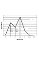
- FIG. 1 is a schematic diagram of a particle size distribution of a projection material according to an embodiment.
- the particle diameter on the horizontal axis shows the lower limit value of the particle diameter section as a representative value.
- the particle diameter d of the projection material is 0.85 mm ⁇ d ⁇ 2.36 mm
- the distribution of the particle diameter d of the projection material is a particle diameter section 1.18 mm ⁇ d ⁇ 1.40 mm in the frequency distribution (JIS G 5904).
- the frequency of the particle diameter section 1.70 mm ⁇ d ⁇ 2.00 mm is 0.4 to 1.0 times the frequency
- the particle diameter section 1.40 mm ⁇ d ⁇ 1. Adjustment is made so that the frequency of 70 mm is 0.2 to 0.7 times.
- the measuring method of particle size distribution is based on Japanese Industrial Standard JIS G 5904 (1966), and is shown by weight distribution.
- the distribution of the particle diameter d of the projection material is, for example, such that the frequency of the particle diameter section 1.70 mm ⁇ d ⁇ 2.00 mm is 0.6 to 0 with respect to the frequency of the particle diameter section 1.18 mm ⁇ d ⁇ 1.40 mm. And the frequency is adjusted so that the frequency of the particle diameter section 1.40 mm ⁇ d ⁇ 1.70 mm is 0.3 to 0.6 times. According to this, the scouring force and the scouring efficiency can be further improved, and it can be suitably used for scouring a casting.
- the projection material having such a particle size distribution is a first projection material in which the particle diameter d is 1.18 mm ⁇ d ⁇ 2.36 mm and the frequency of the particle diameter section 1.70 mm ⁇ d ⁇ 2.00 mm is maximized. And a second projection material in which the particle diameter d is 0.85 mm ⁇ d ⁇ 1.40 mm and the frequency of the particle diameter section 1.18 mm ⁇ d ⁇ 1.40 mm is maximized. it can. That is, the projection material is a mixture of the first projection material and the second projection material.
- the polishing force can be increased.
- the coverage actual dent of the projection material per fixed area
- the second projection material can improve the coverage, but has a low blasting force against a particularly strong sand scale as compared with the first projection material. Therefore, although it has a sufficient blasting force for removing the foundry sand and scale, the scouring force is insufficient to remove seizure and the like generated on the surface of the foundry sand, and the blasting time becomes longer.
- the projection material according to the present embodiment by mixing these projection materials so as to have the particle size distribution described above, it is possible to maintain the respective advantages and supplement the portion where the scouring ability is insufficient.
- the sharpening force can be improved by the first projecting material, and the coverage can be improved by the second projecting material. That is, it is possible to perform the cleaning with both the cleaning force and the cleaning efficiency improved.
- the particle size distribution can be made substantially continuous. Therefore, since the size of the dent by the blast has a continuous distribution, the coverage can be increased and the blast can be efficiently performed.
- the first projection material and the second projection material are classified by using a sieve having a mesh size of 0.85 to 2.36 mm as defined in JIS Z 8801 (2006), by using a known method such as a water atomizing method. It can be prepared by mixing and adjusting to obtain a desired particle size distribution.
- a known centrifugal blasting apparatus as described in Patent Document 1 can be used to polish a casting using the projection material according to the present embodiment.
- the polishing method is not limited to the method using the blasting apparatus.
- the blast device includes a hopper that stores and supplies a fixed amount of the projection material, an impeller unit that projects the projection material, a circulation device that circulates the projection material, a separator that separates the projection material from sand and scale, and a dust collector. .
- the projection material is thrown into the impeller unit from the hopper, and the projection material thrown into the impeller unit is accelerated in the impeller unit and projected onto the casting placed in the projection chamber. Thereby, the casting is polished.
- the projected blast material is collected by a circulation device together with sand and scale removed from the casting by blasting, and sent to the separator.
- the projection material is dropped into an apron, and sand, scales and pulverized fine projection material are selected by the air flow generated by the dust collector, and they are discharged out of the dust collector and the apparatus.
- the projection material effective for the cleaning is supplied again to the impeller unit and recycled.
- the amount of projection material in the device decreases by the amount discharged to the outside of the device, it is necessary to replenish the amount of projection material corresponding to the amount of decrease.
- the decrease in the blast material is detected by the load current value of the impeller unit, and a new blast material is automatically or manually supplied to the hopper.
- the particle size distribution of the in-device projection material is stabilized at a constant particle size distribution different from the particle size distribution of the unused projection material.
- This state of stable particle size distribution is called operating mix. It is important that the projection material is managed so that the particle size distribution of the projection material in the apparatus after forming the operating mix can be efficiently polished.
- the particle size distribution in the blasting apparatus after forming the operating mix is (the ratio of the first particles) ⁇ (the ratio of the second particles) without using a special device or method. ) ⁇ (ratio of the third particles) can be obtained as a characteristic distribution. That is, it can be realized in the normal operation of the blasting apparatus.
- the projection material is classified into a first particle having a particle diameter of 1.18 mm, a second particle having a particle diameter of 1.18 mm or less and exceeding 0.85 mm, and a third particle having a particle diameter of 0.85 mm or less. is doing. Even if the particle size distribution is controlled so that the ratio of the first particles is 60% by weight or more, the ratio of the second particles is 5 to 30% by weight, and the ratio of the third particles is 20% by weight or less. Good.
- This particle size distribution was compared with the particle size distribution according to “ECONOMICAL FUNCTION ASPECTS OF BLAST CLEANING ABRASIVES BLASTING THEORY” (published by WHEEL ABRATOR, 1972), which was previously the guideline for operating mixes in casting polishing.
- the comparison results are shown in Table 1.
- the “third particle” in the present embodiment is a mixture obtained by mixing the third and fourth particles of the conventional pointer in Table 1.
- the projection material according to the present embodiment includes a much larger amount of the first granule having a large scouring force than the conventional projection material due to the addition of the first projection material. A characteristic distribution is shown.
- the first grain has a high scouring force and is particularly effective for removing a strong scale layer in the outermost layer of the casting.
- the polishing time can be shortened by increasing the number of first particles compared to the conventional projection material.
- the amount of the second granule is the same as that of the conventional one, and thereby the coverage can be ensured.
- the third granule has a low scouring force and cannot effectively remove the scale, so it was reduced compared to the conventional projection material. Moreover, since the 3rd particle
- the particle size distribution in the blasting apparatus after forming the operating mix can be set to the above-described distribution suitable for the polishing of the casting.
- the form of the projection material is not limited to shots, and grit, cut wires, and the like can also be used.
- the first projecting material and the second projecting material may be made of the same material, or may be formed of materials having different hardness.
- the projection material according to the present embodiment when blasting of a casting is performed by blasting, it is possible to provide a projection material suitable for blasting of a casting in which both the blasting force and the blasting efficiency are improved. Moreover, it can be set as the projection material from which the particle distribution of the projection material in an apparatus after operating mix formation becomes distribution suitable for the polishing of a casting.
- the work piece used in this test was made of FC250, poured at a pouring temperature of 1350 ° C., thawed 30 minutes after pouring, and cooled at a cooling rate of 3 ° C./min. .
- the product weight is about 3.5 kg.
- the projection test apparatus used for the test was a shot blast SNTX-I type (Shinto Kogyo Co., Ltd.), and the projection speed was 73 m / s and the table rotation speed was 6 rpm.
- the projection material to be used for the test is a first projection material adjusted so that the particle diameter d is 1.18 mm ⁇ d ⁇ 2.36 mm and the frequency of the particle diameter section 1.70 mm ⁇ d ⁇ 2.00 mm is maximized.
- a second projection material adjusted so that the frequency of particle diameter d is 0.85 mm ⁇ d ⁇ 1.40 mm and particle diameter interval 1.18 mm ⁇ d ⁇ 1.40 mm is maximized,
- the hardness is HV450.
- FIG. 2 shows the particle size distribution.
- FIG. 2 is an explanatory diagram showing the particle size distribution of the projection material of the example.
- This particle size distribution satisfied the conditions for the particle size distribution of the projection material according to the embodiment.
- a test with a steel shot having a diameter of 1.7 mm (particle diameter range: 1.40 mm ⁇ d ⁇ 2.36 mm) was also performed.
- the projection density was 150 to 300 kg / m 2 .
- the projection material was put into a projection test apparatus, and after performing continuous operation and replenishment to form an operating mix, a projection test was performed.
- FIG. 3 is an explanatory view showing the surface state of the sample after the blast test.
- the convex and concave portions and character portions (engraved portions) were enlarged to observe the finished state, and visual evaluation was performed. Details of visual appearance are summarized in FIG.
- FIG. 4 is a table for explaining the surface state shown in FIG. As shown in FIGS. 3 and 4, in the comparative example, it was confirmed that a scale exists in the dotted line area surrounded by the dotted line in the range of the projection density of 150 kg / m 2 to 250 kg / m 2 . The scale was removed at a projection density of 300 kg / m 2 .
- a projection density of 300 kg / m 2 was required to finish.
- a scale exists in a dotted line region surrounded by a dotted line when the projection density is in a range of 150 kg / m 2 to 200 kg / m 2 .
- the scale was removed at a projection density of 250 kg / m 2 .
- the working example was finished at a projection density of 250 kg / m 2 .
- FIG. 5 is an explanatory view showing the measurement result of the degree of rust removal of the sample after the polishing test.
- the degree of rust removal increased.
- a degree of rust removal of 90% or more corresponds to the finished point of visual appearance evaluation.
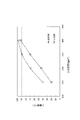
- FIG. 6 is an explanatory diagram showing the results of a life test.
- the number of cycles to reach the cumulative replenishment amount of 100 g of the new projection material was 3400 cycles in the example, compared with 2940 cycles in the comparative example, and a 16% improvement in life was recognized.
- FIG. 7 is an explanatory diagram showing a particle size distribution (estimation) after the operation mix is formed. This particle size distribution satisfies the particle size distribution after forming the operating mix of the projection material according to the embodiment, and it is confirmed that a desired particle size distribution can be obtained in the blasting process using the projection material according to the embodiment. It was done.
Landscapes
- Engineering & Computer Science (AREA)
- Mechanical Engineering (AREA)
- Cleaning In General (AREA)
- Mold Materials And Core Materials (AREA)
Abstract
Description

投射材の形態はショットに限定されるものではなく、グリット、カットワイヤなどを用いることもできる。
本実施形態に係る投射材によれば、鋳物の研掃をブラスト処理により行なうときに、研掃力と研掃効率とをともに向上させた鋳物の研掃に好適な投射材とすることができる。また、オペレーティングミックス形成後の装置内投射材の粒子分布が鋳物の研掃に好適な分布となるような投射材とすることができる。
実施形態に係る投射材を用いた研掃試験を行った。本試験に使用した被加工物は、材質をFC250とし、注湯温度1350℃にて注湯をし、注湯後30分後に解枠し、冷却速度3℃/minにて冷却して得た。製品重量は約3.5kgである。試験に使用した投射試験装置は、ショットブラストSNTX-I型(新東工業株式会社)であり、投射速度73m/s、テーブル自転速度6rpmにて実施した。
投射材の寿命試験は、SAE J445に規程の100%Replacement Methodに準拠し、アーヴィン式ライフテスターを用い、投射速度60m/s、カットスクリーン0.710mmの条件で行った。結果を図6に示す。
図6は、寿命試験の結果を示す説明図である。新しい投射材の累計補給量100gに到達するサイクル数は、比較例の2940サイクルに対し、実施例では3400サイクルであり、16%の寿命向上が認められた。
Claims (5)
- 鋳物の表面をブラスト処理により研掃するために用いる鉄系の投射材であって、
前記投射材は、ビッカース硬度がHV300~600の範囲であり、
前記投射材の粒子径dは、0.85mm<d≦2.36mmであり、
前記投射材の粒子径dの分布は、頻度分布における粒子径区間1.18mm<d≦1.40mmの頻度が最大となり、当該頻度に対して、粒子径区間1.70mm<d≦2.00mmの頻度が0.4~1.0倍であり、かつ粒子径区間1.40mm<d≦1.70mmの頻度が0.2~0.7倍である、
投射材。 - 前記投射材の粒子径dの分布は、頻度分布における粒子径区間1.18mm<d≦1.40mmの頻度に対して、粒子径区間1.70mm<d≦2.00mmの頻度が0.6~0.8倍であり、かつ粒子径区間1.40mm<d≦1.70mmの頻度が0.3~0.6倍である請求項1に記載の投射材。
- 粒子径dが1.18mm<d≦2.36mmであって粒子径区間1.70mm<d≦2.00mmの頻度が最大となる第1投射材と、粒子径dが0.85mm<d≦1.40mmであって粒子径区間1.18mm<d≦1.40mmの頻度が最大となる第2投射材との混合物である請求項1又は2に記載の投射材。
- ブラスト装置の操業により一定の粒子径分布で安定するオペレーティングミックス形成後の投射材の粒子径分布が、粒子径1.18mmを超える第1粒体と、粒子径1.18mm以下で0.85mmを超える第2粒体と、粒子径0.85mm以下の第3粒体と、に区分したときに、
(第1粒体の比率)≧(第2粒体の比率)≧(第3粒体の比率)
を充足する請求項1~3の何れか一項に記載の投射材。 - 第1粒体の比率は60重量%以上、第2粒体の比率は5~30重量%、第3粒体の比率は20重量%以下である請求項4に記載の投射材。
Priority Applications (4)
| Application Number | Priority Date | Filing Date | Title |
|---|---|---|---|
| BR112017011568-9A BR112017011568B1 (pt) | 2015-03-12 | 2016-02-02 | meio de jateamento à base de ferro usado para a limpeza por jateamento de uma superfície |
| JP2017504906A JP6213694B2 (ja) | 2015-03-12 | 2016-02-02 | 投射材 |
| CN201680003889.6A CN107000165B (zh) | 2015-03-12 | 2016-02-02 | 投射材料 |
| KR1020177027037A KR102460923B1 (ko) | 2015-03-12 | 2016-02-02 | 투사재 |
Applications Claiming Priority (2)
| Application Number | Priority Date | Filing Date | Title |
|---|---|---|---|
| JP2015049746 | 2015-03-12 | ||
| JP2015-049746 | 2015-03-12 |
Publications (1)
| Publication Number | Publication Date |
|---|---|
| WO2016143413A1 true WO2016143413A1 (ja) | 2016-09-15 |
Family
ID=56880474
Family Applications (1)
| Application Number | Title | Priority Date | Filing Date |
|---|---|---|---|
| PCT/JP2016/053057 Ceased WO2016143413A1 (ja) | 2015-03-12 | 2016-02-02 | 投射材 |
Country Status (5)
| Country | Link |
|---|---|
| JP (1) | JP6213694B2 (ja) |
| KR (1) | KR102460923B1 (ja) |
| CN (1) | CN107000165B (ja) |
| BR (1) | BR112017011568B1 (ja) |
| WO (1) | WO2016143413A1 (ja) |
Cited By (3)
| Publication number | Priority date | Publication date | Assignee | Title |
|---|---|---|---|---|
| WO2017221894A1 (ja) * | 2016-06-23 | 2017-12-28 | 新東工業株式会社 | 投射材及びその投射材を用いた金属製品の表面処理方法 |
| WO2019146530A1 (ja) * | 2018-01-25 | 2019-08-01 | 新東工業株式会社 | 投射材及びブラスト処理方法 |
| WO2019146529A1 (ja) * | 2018-01-25 | 2019-08-01 | 新東工業株式会社 | 投射材及びブラスト処理方法 |
Citations (5)
| Publication number | Priority date | Publication date | Assignee | Title |
|---|---|---|---|---|
| JPH0788770A (ja) * | 1993-09-20 | 1995-04-04 | Japan Metals & Chem Co Ltd | 研掃材 |
| JP2001353661A (ja) * | 2000-06-15 | 2001-12-25 | Sinto Brator Co Ltd | ブラスト処理用投射材 |
| JP2002355762A (ja) * | 2001-05-30 | 2002-12-10 | Sharp Corp | ブラスト屑の分別方法および分別装置 |
| US20050268996A1 (en) * | 2002-01-16 | 2005-12-08 | Bogers Jacobus Maria M | Method and device for galvanizing objects |
| JP2014054686A (ja) * | 2012-09-11 | 2014-03-27 | Yoshikawa Kogyo Co Ltd | ブラスト装置 |
Family Cites Families (3)
| Publication number | Priority date | Publication date | Assignee | Title |
|---|---|---|---|---|
| JP3027980B2 (ja) | 1993-04-16 | 2000-04-04 | 新東工業株式会社 | 鋳物の砂落し方法 |
| JP2003342555A (ja) * | 2002-05-30 | 2003-12-03 | Ikk Shotto Kk | 混合金属系粒状物 |
| JP5190238B2 (ja) * | 2006-09-28 | 2013-04-24 | 新日鐵住金株式会社 | 高耐食性防錆塗料、高耐食性鉄鋼材料及び鋼構造物 |
-
2016
- 2016-02-02 CN CN201680003889.6A patent/CN107000165B/zh active Active
- 2016-02-02 JP JP2017504906A patent/JP6213694B2/ja active Active
- 2016-02-02 WO PCT/JP2016/053057 patent/WO2016143413A1/ja not_active Ceased
- 2016-02-02 KR KR1020177027037A patent/KR102460923B1/ko active Active
- 2016-02-02 BR BR112017011568-9A patent/BR112017011568B1/pt active IP Right Grant
Patent Citations (5)
| Publication number | Priority date | Publication date | Assignee | Title |
|---|---|---|---|---|
| JPH0788770A (ja) * | 1993-09-20 | 1995-04-04 | Japan Metals & Chem Co Ltd | 研掃材 |
| JP2001353661A (ja) * | 2000-06-15 | 2001-12-25 | Sinto Brator Co Ltd | ブラスト処理用投射材 |
| JP2002355762A (ja) * | 2001-05-30 | 2002-12-10 | Sharp Corp | ブラスト屑の分別方法および分別装置 |
| US20050268996A1 (en) * | 2002-01-16 | 2005-12-08 | Bogers Jacobus Maria M | Method and device for galvanizing objects |
| JP2014054686A (ja) * | 2012-09-11 | 2014-03-27 | Yoshikawa Kogyo Co Ltd | ブラスト装置 |
Cited By (8)
| Publication number | Priority date | Publication date | Assignee | Title |
|---|---|---|---|---|
| WO2017221894A1 (ja) * | 2016-06-23 | 2017-12-28 | 新東工業株式会社 | 投射材及びその投射材を用いた金属製品の表面処理方法 |
| JPWO2017221894A1 (ja) * | 2016-06-23 | 2019-04-11 | 新東工業株式会社 | 投射材及びその投射材を用いた金属製品の表面処理方法 |
| WO2019146530A1 (ja) * | 2018-01-25 | 2019-08-01 | 新東工業株式会社 | 投射材及びブラスト処理方法 |
| WO2019146529A1 (ja) * | 2018-01-25 | 2019-08-01 | 新東工業株式会社 | 投射材及びブラスト処理方法 |
| JPWO2019146529A1 (ja) * | 2018-01-25 | 2021-01-07 | 新東工業株式会社 | 投射材及びブラスト処理方法 |
| JP7115495B2 (ja) | 2018-01-25 | 2022-08-09 | 新東工業株式会社 | ブラスト処理方法 |
| US11478897B2 (en) | 2018-01-25 | 2022-10-25 | Sintokogio, Ltd. | Blasting processing method using shot media |
| US11511393B2 (en) | 2018-01-25 | 2022-11-29 | Sintokogio, Ltd. | Projection material and blasting method |
Also Published As
| Publication number | Publication date |
|---|---|
| KR102460923B1 (ko) | 2022-11-01 |
| KR20170128364A (ko) | 2017-11-22 |
| CN107000165A (zh) | 2017-08-01 |
| JPWO2016143413A1 (ja) | 2017-07-20 |
| CN107000165B (zh) | 2018-11-02 |
| JP6213694B2 (ja) | 2017-10-18 |
| BR112017011568B1 (pt) | 2021-06-08 |
| BR112017011568A2 (pt) | 2018-01-02 |
Similar Documents
| Publication | Publication Date | Title |
|---|---|---|
| JP6213695B2 (ja) | 鋳物の研掃方法 | |
| US9314902B2 (en) | Blasting agent and blasting method | |
| JP6213694B2 (ja) | 投射材 | |
| JPWO2011052287A1 (ja) | 亜鉛基合金ショット | |
| WO2016174897A1 (ja) | スケール除去方法 | |
| JP6841280B2 (ja) | 投射材及びその投射材を用いた熱間鍛造品の表面処理方法 | |
| JP2013010976A (ja) | 低炭素系鋳鋼ショット | |
| JP5777201B2 (ja) | スチール系投射材 | |
| KR100420127B1 (ko) | 블라스트처리용 투사재 및 이를 사용하는 블라스트가공방법 | |
| WO2012081276A1 (ja) | 亜鉛基合金ショット | |
| JP6658772B2 (ja) | 鋳鋼製投射材 | |
| JP5787215B2 (ja) | 亜鉛基合金ショット | |
| JP7618673B2 (ja) | 噴流切削加工用研磨剤 | |
| JP5939339B2 (ja) | 亜鉛基合金ショット | |
| JP2012139790A (ja) | 投射材の寿命に優れたショットピーニング方法 | |
| JP7205535B2 (ja) | ブラスト加工に用いられるショット | |
| JP7705128B1 (ja) | ニッケル基合金、およびウェットショットピーニング用投射材 | |
| JP7641127B2 (ja) | ショットブラスト用研掃材 | |
| CN111615438A (zh) | 投射材料和喷丸处理方法 | |
| US20160167198A1 (en) | Blasting agent and blasting method |
Legal Events
| Date | Code | Title | Description |
|---|---|---|---|
| 121 | Ep: the epo has been informed by wipo that ep was designated in this application |
Ref document number: 16761385 Country of ref document: EP Kind code of ref document: A1 |
|
| ENP | Entry into the national phase |
Ref document number: 2017504906 Country of ref document: JP Kind code of ref document: A |
|
| REG | Reference to national code |
Ref country code: BR Ref legal event code: B01A Ref document number: 112017011568 Country of ref document: BR |
|
| NENP | Non-entry into the national phase |
Ref country code: DE |
|
| ENP | Entry into the national phase |
Ref document number: 20177027037 Country of ref document: KR Kind code of ref document: A |
|
| ENP | Entry into the national phase |
Ref document number: 112017011568 Country of ref document: BR Kind code of ref document: A2 Effective date: 20170531 |
|
| 122 | Ep: pct application non-entry in european phase |
Ref document number: 16761385 Country of ref document: EP Kind code of ref document: A1 |