WO2016174897A1 - スケール除去方法 - Google Patents
スケール除去方法 Download PDFInfo
- Publication number
- WO2016174897A1 WO2016174897A1 PCT/JP2016/054568 JP2016054568W WO2016174897A1 WO 2016174897 A1 WO2016174897 A1 WO 2016174897A1 JP 2016054568 W JP2016054568 W JP 2016054568W WO 2016174897 A1 WO2016174897 A1 WO 2016174897A1
- Authority
- WO
- WIPO (PCT)
- Prior art keywords
- scale removal
- particle size
- projection material
- projection
- size distribution
- Prior art date
Links
Images


Classifications
-
- B—PERFORMING OPERATIONS; TRANSPORTING
- B24—GRINDING; POLISHING
- B24C—ABRASIVE OR RELATED BLASTING WITH PARTICULATE MATERIAL
- B24C1/00—Methods for use of abrasive blasting for producing particular effects; Use of auxiliary equipment in connection with such methods
- B24C1/08—Methods for use of abrasive blasting for producing particular effects; Use of auxiliary equipment in connection with such methods for polishing surfaces, e.g. smoothing a surface by making use of liquid-borne abrasives
- B24C1/086—Descaling; Removing coating films
-
- B—PERFORMING OPERATIONS; TRANSPORTING
- B21—MECHANICAL METAL-WORKING WITHOUT ESSENTIALLY REMOVING MATERIAL; PUNCHING METAL
- B21B—ROLLING OF METAL
- B21B45/00—Devices for surface or other treatment of work, specially combined with or arranged in, or specially adapted for use in connection with, metal-rolling mills
- B21B45/04—Devices for surface or other treatment of work, specially combined with or arranged in, or specially adapted for use in connection with, metal-rolling mills for de-scaling, e.g. by brushing
- B21B45/06—Devices for surface or other treatment of work, specially combined with or arranged in, or specially adapted for use in connection with, metal-rolling mills for de-scaling, e.g. by brushing of strip material
-
- B—PERFORMING OPERATIONS; TRANSPORTING
- B24—GRINDING; POLISHING
- B24C—ABRASIVE OR RELATED BLASTING WITH PARTICULATE MATERIAL
- B24C1/00—Methods for use of abrasive blasting for producing particular effects; Use of auxiliary equipment in connection with such methods
-
- B—PERFORMING OPERATIONS; TRANSPORTING
- B24—GRINDING; POLISHING
- B24C—ABRASIVE OR RELATED BLASTING WITH PARTICULATE MATERIAL
- B24C11/00—Selection of abrasive materials or additives for abrasive blasts
-
- B—PERFORMING OPERATIONS; TRANSPORTING
- B24—GRINDING; POLISHING
- B24C—ABRASIVE OR RELATED BLASTING WITH PARTICULATE MATERIAL
- B24C5/00—Devices or accessories for generating abrasive blasts
- B24C5/06—Impeller wheels; Rotor blades therefor
-
- B—PERFORMING OPERATIONS; TRANSPORTING
- B24—GRINDING; POLISHING
- B24C—ABRASIVE OR RELATED BLASTING WITH PARTICULATE MATERIAL
- B24C7/00—Equipment for feeding abrasive material; Controlling the flowability, constitution, or other physical characteristics of abrasive blasts
-
- B—PERFORMING OPERATIONS; TRANSPORTING
- B24—GRINDING; POLISHING
- B24C—ABRASIVE OR RELATED BLASTING WITH PARTICULATE MATERIAL
- B24C7/00—Equipment for feeding abrasive material; Controlling the flowability, constitution, or other physical characteristics of abrasive blasts
- B24C7/0092—Equipment for feeding abrasive material; Controlling the flowability, constitution, or other physical characteristics of abrasive blasts the abrasive material being fed by mechanical means, e.g. by screw conveyors
Definitions
- the present disclosure relates to a scale removal method for removing a scale such as an oxide formed on a base material surface of a workpiece made of an iron-based material by shot blasting.
- a wire rod made of ordinary steel, alloy steel, tool steel, bearing steel or the like becomes billet or the like by melting and continuous casting.
- a billet etc. turns into a coil or a bar material through a rolling process.
- the manufactured coil material or the like is removed from the scale by a bender or shot blasting process, and is subjected to a wire drawing or chemical conversion process. If it is difficult to remove the scale, pickling is performed before the vendor or shot blasting. However, pickling treatment is avoided as much as possible from the viewpoint of environmental impact.
- the projecting material repeats the cycle of projection, recovery, fine powder removal, and projection.
- the projection material is pulverized to become fine powder.
- Such fine powder is selected and removed by a separator or the like. Since the amount of blasting material in the blasting device is reduced by the amount removed, the blasting material is replenished according to the amount of reduction, but if the blasting material is supplied, crushed, and discharged outside the device repeatedly, The particle size distribution of the projection material is different from the initial particle size distribution.
- scale removal and preliminary scale removal are collectively referred to as scale removal
- particles different from the initial stage of the projection material in the apparatus It is necessary to manage the diameter distribution so that it is a suitable condition for the scale removal process.
- the projection material used for the scale removal treatment is generally used for other purposes such as deburring and improving the surface roughness.
- the particle diameter and hardness can be appropriately selected according to the application, there is no projection material in which the particle diameter distribution or the like is specifically adjusted for the scale removal treatment.
- the scale removal process described above is often performed as a continuous process in which a process is performed while conveying a workpiece, and a high processing speed is required.
- the scale removal force is increased by using a projection material having a large particle diameter.
- the following problems occur.
- the shot blasting process of the wire rod a phenomenon that the swing of the wire rod increases due to the collision of the projection material occurs. Thereby, there is a problem that the projection material is not effectively projected onto the wire and the efficiency of scale removal is reduced.
- a projection material is projected by a blast device, and the scale removal method performs removal of the scale of a workpiece made of an iron-based material, Projection material loading process in which an unused projection material having a Vickers hardness in the range of HV300 to 600 (Japanese Industrial Standard JIS Z 2244) is loaded into the blasting device, and the particles of the projecting material in the blasting device by operation of the blasting device A particle size distribution adjusting step for adjusting the particle size distribution to a predetermined particle size distribution, and a scale removing step for projecting the projection material after the particle size distribution adjusting step onto the surface of the workpiece.
- the particle size distribution of the projection material after the adjustment step is a first particle having a particle size of more than 300 ⁇ m, a second particle having a particle size of 300 ⁇ m or less and exceeding 75 ⁇ m, and a particle size of 75 ⁇ m or less.
- the particle size distribution of the projection material after adjusting the particle size distribution contains a large amount of the second particles for ensuring the coverage, and then the first particles with the largest scale removal power.
- the ratio of the second particles may be 60% by weight or more, the ratio of the first particles may be 10 to 40% by weight, and the ratio of the third particles may be 10% by weight or less.
- the workpiece may be formed by rolling.
- the scale removal processing of a workpiece formed by rolling is often performed as a continuous processing in which processing is performed while conveying the workpiece, and the processing speed is high. It is required to be fast. Since this scale removal method has both high scale removal power and scale removal processing efficiency, it can be used for a workpiece in which a scale is formed on the surface of a base material by rolling.
- the work piece may be a wire.
- the work piece is a wire rod
- the impact force of the projection material is large, a phenomenon occurs in which the wire rod shakes greatly due to the collision of the projection material, the projection material is not effectively projected onto the wire rod, and the scale removal There is a problem that efficiency is lowered.
- this scale removal method a large amount of second particles having a particle diameter smaller than that of the first particles is contained. For this reason, since this scale removal method can reduce the impact force of a projection material conventionally, it can suppress the shaking of a wire. Therefore, this scale removal method enables efficient scale removal.
- the particle diameter d of the projection material is 125 ⁇ m ⁇ d ⁇ 600 ⁇ m, and the frequency of the particle diameter d of the projection material is 212 ⁇ m ⁇ d ⁇ 300 ⁇ m in the frequency distribution (JIS G 5904).
- the frequency of the particle diameter section 355 ⁇ m ⁇ d ⁇ 500 ⁇ m may be 0.3 to 1.0 times.
- the projection material may be a mixture of a first projection material composed of particles having a particle size number 030 and a second projection material composed of particles having a particle size number 040.
- the particle size number is defined in JIS Z0311: 2004.
- the projection material used in this scale removal method mixes the first projection material adjusted so as to improve the scale removal force and the second projection material adjusted so as to improve the coverage. Can be produced.
- FIG. 1 is an explanatory diagram illustrating an example of a blasting apparatus 1 used in the scale removal method according to the embodiment.
- 1A is an overall configuration diagram of the blasting apparatus 1
- FIG. 1B is an explanatory diagram showing an internal configuration of the projection chamber as seen in the direction of arrows AA in FIG. is there.
- the blasting apparatus 1 has a configuration for performing a scale removal process of a wire as the workpiece W.
- the scale removal method according to the embodiment is not limited to the method using the blast device 1.
- the blast device 1 includes a hopper 11 that stores and supplies a fixed amount of the projection material, an impeller 22 that projects the projection material, a bucket elevator 13 that circulates the projection material, a projection material and a scale (mainly iron oxide), , A dust collector 15, a projection chamber 20, a control device (not shown), a carry-in mechanism for carrying a workpiece into the projection chamber 20, and a carry-out mechanism for carrying out the scale-removed workpiece from the projection chamber 20.
- a hopper 11 that stores and supplies a fixed amount of the projection material
- an impeller 22 that projects the projection material
- a bucket elevator 13 that circulates the projection material
- a projection material and a scale mainly iron oxide
- the projection chamber 20 is arranged at predetermined intervals in the traveling direction of the workpiece inside the wire inlet / outlet and the projection chamber 20, and the guide member 21 for extending the wire in a straight line, and the traveling wire
- four impellers 22 for projecting the projection material S from the top, bottom, left, and right directions, and a screw conveyor 23 attached to the bottom for collecting the projected projection material are provided.
- the hopper 11 includes a storage portion 11a in which the projection material is stored, and a cut gate 11b that is provided below the storage portion 11a and for supplying the projection material to the impeller 22 in a fixed amount.
- the cut gate 11b has a variable opening area and can supply a certain amount of projection material to the impeller 22.
- the impeller 22 accelerates the projection material supplied from the hopper 11 by a rotating blade, and projects the projection material onto the workpiece that is carried into the projection chamber 20 and travels. Thereby, the scale removal process is performed on the workpiece.
- the bucket elevator 13 is connected to the projection chamber 20.
- the projection material after the scale removal processing, the scale removed from the workpiece (hereinafter referred to as the projection material) are conveyed to the bucket elevator 13 by the screw conveyor 23.
- the bucket elevator 13 conveys the projection material and the like above the blasting apparatus 1 and supplies the blast material to the hopper 11 through the throwing-out portion 16.
- a punching metal 18 is disposed between the throw-out portion 16 and the hopper 11. The punching metal 18 can remove a large scale or the like from the projection material or the like in advance.
- the bucket elevator 13 is provided with a shot supply port 13a.
- the projection material can be supplied from the shot supply port 13a.
- the throwing-out part 16 is provided connected to the cyclone 14 and the hopper 11.
- the cyclone 14 will be described.
- the blast apparatus 1 When the blast apparatus 1 is operated, the projection material is broken and fine powder is generated. At that time, there is a concern that dust is generated in the projection chamber 20 and that the dust may cause a dust explosion, or that the quality of the workpiece may be deteriorated by adhering to or piercing the workpiece. Or, the projection material becomes too fine, and the scale cannot be completely removed. Therefore, in the throwing-out part 16, dust collection is performed by the airflow of the predetermined
- the projection material since the projection material is small in size, it may be classified by the cyclone 14 together with the generated fine powder (removed scale or pulverized fine projection material).
- the fine powder is collected by the dust collector 15 and discharged out of the apparatus.
- the wind speed and the amount of airflow generated by suction by the dust collector 15 are controlled by the opening degree of the damper 19 provided between the dust collector 15 and the cyclone 14.
- the classification ability of the cyclone 14 is controlled.
- the classification accuracy is adjusted, and a desired particle size distribution described later is formed and maintained.
- the projection material effective for removing the scale is supplied again to the projection chamber 20 and is circulated.
- the amount of projection material in the apparatus decreases by the amount discharged to the outside of the blast device 1, it is necessary to replenish the amount of projection material corresponding to the decrease amount.
- the decrease of the projection material is detected by the load current value of the impeller 22, and a new projection material is supplied from the shot supply port 13a.
- a control device is a computer including a CPU, a ROM, a RAM, and the like, and controls the configuration requirements of the blast device 1 described above.
- FIG. 2 is an explanatory diagram illustrating steps of the scale removal method according to the embodiment.
- the blasting apparatus 1 is activated, and in step S1, a projection material filling process is performed.
- a projection material loading step an unused projection material is loaded into the blast device 1 from the shot supply port 13a. The projection material will be described later.
- a step of adjusting the particle size distribution (particle size distribution adjusting step) is performed. It is important to manage the particle size distribution of the projection material in the apparatus after adjusting the particle size distribution so that the scale can be efficiently removed.
- step S2 the particle size distribution in the blasting apparatus after the particle size distribution adjustment satisfies the characteristic (second particle ratio) ⁇ (first particle ratio) ⁇ (third particle ratio).
- the distribution is controlled.
- the projection material is divided into a first particle having a particle diameter of 300 ⁇ m, a second particle having a particle diameter of 300 ⁇ m or less and exceeding 75 ⁇ m, and a third particle having a particle diameter of 75 ⁇ m or less.
- Each particle has a particle size distribution rather than a single particle size.
- the particle size distribution can be controlled so that the ratio of the second particles is 60% by weight or more, the ratio of the first particles is 10 to 40% by weight, and the ratio of the third particles is 10% by weight or less. Good.
- the particle size distribution of the projection material after adjusting the particle size distribution contains a large amount of second particles smaller than the conventionally used particle size, and the first particles having a large scale removing power. Then, the distribution is characteristic of reducing or eliminating the third particles which are contained in large amounts and have low scale removing power. Since the coverage can be ensured by containing a large amount of the second granule, the scale removal processing efficiency can be improved.
- the first granule has a high scale removing power and can shorten the scale removing time. And since the 3rd granule has low scale removal power and cannot remove scale effectively, it reduces as much as possible.
- FIG. 3 is an explanatory view showing an example of a particle size distribution adjusting step.
- the particle size distribution adjusting step includes a method of adjusting to a particle size distribution in an operating mix state and a method of introducing a predetermined projection material so as to positively obtain a desired particle size distribution.
- the particle size distribution of the projection material in the blast device 1 is a constant particle size different from the unused projection material distribution. Stable in distribution.
- the operating mix refers to this state of stable particle size distribution.
- an explanation will be given by taking as an example the adjustment of the particle size distribution to the state after the operating mix is formed.
- step S21 for example, a dummy workpiece made of the same material as that of the workpiece is prepared, and in step S22, the blasting device 1 is activated to form a dummy workpiece.
- a projecting material is projected under the same conditions as when removing the scale of the workpiece, and a series of operations for repeatedly discharging and replenishing fine powder outside the apparatus is performed.
- the particle size distribution of the projection material in the blast apparatus 1 becomes a particle size distribution different from the particle size distribution of the unused projection material.
- the dummy workpiece may be run like an actual workpiece or may be in a stationary state. Further, the projection material may be blanked without using a dummy workpiece.
- step S23 the same determination as in step S5 described later is performed.
- the process proceeds to step S25, and then returns to step S23. If the projection material is not replenished, the process proceeds to step S24.
- step S24 it is determined whether or not the projection time has reached an equivalent time set in advance to form an operating mix. If the projection time has reached the equivalent time, the process proceeds to step S26, and if not, the process returns to step S23.
- step S26 the projection material is sampled to measure the particle size distribution, and it is evaluated whether a desired particle size distribution (operating mix) is formed.
- sampling of the projection material can be performed from the cut gate 11 b, the bucket elevator 13, and the throwing-out portion 16. If it is determined that a desired operating mix has been formed (step S26: YES), the process proceeds to step S3.
- FIG. 4 is an explanatory diagram showing changes in the particle size distribution in the particle size distribution adjusting step.
- FIG. 4 schematically shows a process in which an operating mix is formed.
- the particle diameter on the horizontal axis shows the lower limit value of the particle diameter section as a representative value.
- the projection material that showed the particle size distribution of (A) in an unused state has a reduced weight fraction of the first particles and a broad particle size distribution of the second particles. It will become. This is because the first particles are pulverized and reduced, and the second particles and the like are generated.
- the weight fraction of the first granules further decreases, and the particles below the second granules increase.
- the third particles and below are discharged out of the machine and the increase is suppressed.
- the first granule is replenished as much as the initial shot corresponds to the discharge amount, the decrease is suppressed. Therefore, the ratio of the 1st grain object, the 2nd grain object, and the 3rd grain object is stabilized in the state of (C).
- step S26 If it is determined that the desired operating mix is not formed (step S26: NO), the process proceeds to step S27, the opening degree of the damper 19 is adjusted, and then the process returns to step S22.
- step S27 for example, when there are many small-diameter particles, the opening degree of the damper 19 can be lowered and the classification force of the cyclone 14 can be lowered to remove it.
- each process may be automatic or manual. When each process is automatically performed, each process is performed by the control device.
- step S3 the workpiece to be scale-removed is set in the projection chamber 20.
- the wire that is the workpiece is sequentially inserted into the guide member 21 from the upstream in the conveying direction (left direction in FIG. 1B) and positioned and arranged in a straight line. Then, the wire is pulled in a state where a predetermined tension is applied and travels in the right direction.
- the scale formed on the surface of the workpiece is removed by projecting the projection material with the particle size distribution adjusted in step S4 (scale removal step).
- the scale removal process is performed by projecting the projection material from the impellers 22 provided in the four directions onto the wire rod that is continuously supplied into the projection chamber 20 and travels. And the wire rod in which the scale removal process was performed is continuously carried out of the projection chamber 20 from a carry-out port, and is conveyed to the next process.
- step S5 it is determined whether or not to replenish the projection material based on the load current value of the ammeter of the impeller 22 that is projecting the projection material. If the load current value is larger than the preset current value and less than or equal to the predetermined fluctuation value, it is determined that the projection material is not replenished, and the process proceeds to step S6. When the load current value is equal to or less than the preset current value or exceeds a predetermined fluctuation value, it is determined that the projection material is replenished, and the process proceeds to step S7. In step S7, a predetermined amount of new projection material is supplied from the shot supply port 13a, and the process returns to step S5. The projection material is replenished by a predetermined amount set in consideration of the load of the bucket elevator and the like. Thereby, a desired particle size distribution (in this embodiment, an operating mix) can be maintained.
- a desired particle size distribution in this embodiment, an operating mix
- step S6 it is determined whether or not there is a workpiece.
- the process proceeds to step S5, and when the workpiece does not exist, that is, when all the workpieces to be subjected to the scale removal process are carried out of the projection chamber 20. It progresses to step S8 and the projection of a projection material is complete
- the presence / absence of the workpiece may be determined by visual observation, or may be determined by a wire rod detection device that makes a determination using a magnetic or optical method.
- step S9 it is determined whether or not to continue the scale removal process. When there is no next workpiece, the series of operations is terminated, and when there is a next workpiece, the operations after step S3 are repeated.
- the particle size distribution of the projection material after the particle size distribution adjustment can be made a distribution suitable for scale removal of the workpiece. For this reason, the scale removal method described above can improve both the scale removal force and the scale removal processing efficiency.
- the scale removal method according to the present embodiment can be used for a workpiece having a scale formed on the surface of a base material by rolling, such as a wire or a steel plate.
- the scale of such a workpiece is firmly attached to the base material with a thickness of about several tens of ⁇ m, and a high scale removing force is required.
- scale removal processing of a workpiece is often performed as a continuous processing in which processing is performed while the workpiece is being conveyed, and a high processing speed is required. Since the scale removal method according to the present embodiment has both high scale removal power and scale removal processing efficiency, it can be used for a workpiece having a scale formed on the surface of a base material by rolling.
- the scale removal method according to the present embodiment a large amount of second particles having a particle diameter smaller than that of the first particles is contained. For this reason, since the scale removal method according to the present embodiment can reduce the impact force of the projection material as compared with the related art, it is possible to suppress the shaking of the wire and to efficiently remove the scale. Furthermore, since the scale removal method according to the present embodiment enables efficient scale removal, it is possible to omit the pickling treatment that has been conventionally performed as a pretreatment for the scale removal treatment.
- the scale removal method according to the present embodiment can significantly improve the coverage by the second granule. Moreover, since the scale removal method according to the present embodiment can reduce the size of the dent, the surface roughness can also be improved.
- the projectile is a shot selected from the range of Vickers hardness HV300-600.
- the material and shape can be selected as appropriate, but in this embodiment, a spherical shot made of an iron-based material is used.
- the iron-based material for example, C: 0.8 to 1.2% by weight, Mn: 0.35 to 1.20% by weight, Si: 0.40 to 1.50% by weight, P ⁇ 0.
- a component system containing 05 wt%, S ⁇ 0.05 wt%, the balance Fe and inevitable impurities, and having a tempered martensite structure or a similar structure can be employed.
- Such particles can be prepared by a known method such as a water atomizing method.
- the projection material has sufficient hardness with respect to the workpiece at HV300 or more, and the projection material has sufficient toughness at HV600 or less.
- the projection material of this embodiment has sufficient hardness and toughness, it can be used suitably for scale removal of the workpiece surface.
- Vickers hardness HV is based on Japanese Industrial Standard JIS Z 2244 (2009).
- FIG. 5 is a schematic diagram of a particle size distribution of a projection material as an example that can be used in the scale removal method according to the embodiment.
- the particle diameter d of the projection material is 125 ⁇ m ⁇ d ⁇ 600 ⁇ m, and the distribution of the particle diameter d of the projection material has the maximum frequency of the particle diameter section 212 ⁇ m ⁇ d ⁇ 300 ⁇ m in the frequency distribution (JIS G 5904).
- the frequency is adjusted so that the frequency of the particle diameter section 355 ⁇ m ⁇ d ⁇ 500 ⁇ m is 0.3 to 1.0 times.
- the measuring method of the particle size distribution is based on Japanese Industrial Standard JIS G 5904 (1966) and is shown by weight distribution.
- a projection material having such a particle size distribution can be prepared by mixing a first projection material made of particles having a particle size number 030 and a second projection material made of particles having a particle size number 040. That is, the projection material is a mixture of the first projection material and the second projection material.
- the scale removal force can be increased. However, since the number of particles per unit weight is reduced, the coverage (actual dent area of the projection material per fixed area) is reduced. Leading to a decline.
- the second projection material can improve the coverage, but the scale removal force is lower than that of the first projection material, so the scale removal time becomes longer.
- the projection material according to the embodiment by mixing these projection materials so as to have the particle size distribution described above, it is possible to maintain the respective advantages and supplement the portion where the scale removal capability is insufficient.
- the scale removal force can be improved by the first projection material, and the coverage can be improved by the second projection material. That is, scale removal with improved scale removal power and scale removal processing efficiency can be performed.
- the first and second projection materials are classified by using a sieve having a sieve size of 600 ⁇ m to 125 ⁇ m as defined in JIS Z 8801 (2006) using a known method such as a water atomization method to obtain a desired particle diameter. It can be prepared by mixing and adjusting so as to obtain a distribution.
- the particle size distribution in the blasting apparatus after the particle size distribution adjusting step can be set to the above-described distribution suitable for scale removal of the workpiece without using a special device or method. .
- the projection material supplied in steps S25 and S7 can be different from the projection material loaded in step S1.
- a large diameter projection material can be supplied to form a desired operating mix.
- the form of the projection material is not limited to shots, and grit, cut wires, and the like can also be used.
- the 1st projection material and the 2nd projection material are good also as the same material, and may form with the material from which hardness differs.
- the particle size distribution of the projection material after the particle size distribution adjustment contains a large amount of the second particles for ensuring the coverage, and the first particles having a large scale removal power.
- it has a characteristic distribution in which the third granule is contained in a large amount and the scale removing power is low or eliminated.
- the scale removal method according to the present embodiment can improve the scale removal force by the first granules and shorten the scale removal time, and can ensure the coverage by the second granules. Therefore, the scale removal method according to the present embodiment can improve both the scale removal power and the scale removal processing efficiency.
- the scale removing method according to the present embodiment can be used for a workpiece having a scale formed on the surface of a base material by rolling, such as a wire or a steel plate.
- a workpiece is a wire
- the impact force of the projection material can be reduced as compared with the prior art.
- the scale removal method according to the present embodiment can suppress the shaking of the wire, and enables efficient scale removal.
- the scale removal method according to the present embodiment can omit the pickling treatment that has been conventionally performed as a pretreatment for the scale removal treatment.
- the workpiece is a steel plate
- a sufficient amount of cracks and delamination required in the subsequent steps can be introduced in the preliminary scale removal process in which the scale is cracked or delaminated by shot blasting.
- the scale removal method according to the present embodiment can reduce the size of the dent, the surface roughness can also be improved.
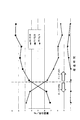
- FIG. 6 is an explanatory diagram showing the relationship between the particle size distribution of the projection material and the finished state of the workpiece after the scale removal process in each particle size distribution.
- the particle size distribution was measured by sampling the projection material at predetermined time intervals. The finished situation was visually observed and evaluated.
- the weight fraction of the first granules decreases and the weight fraction of the second granules increases.
- the deflection of the wire rod is large, and the probability of deviating from the projection pattern (projection range) increases, so the actual projection density decreases.
- the number of particles at the time of comparing with the same particle weight will fall, and a coverage will fall.
- the scale tends to remain and the finished state was not good.
- the second particles were 60% by weight or more and the first particles were 40% by weight or less, the finished state was good. Thereby, it was confirmed that sufficient scale removal was possible by the particle size distribution of this embodiment.
- Example 2 Examination of impact force and coverage by blasting material Using a blasting material produced by mixing a first blasting material made of steel shot with a particle size number 030 and a second blasting material made of steel shot with a particle size number 040 Then, the particle size distribution after adjusting the particle size distribution was evaluated (Examples (1) and (2)). Further, as a comparative example (3), a steel shot of ⁇ 300 ⁇ m (particle size range: 300 ⁇ m ⁇ d ⁇ 600 ⁇ m) was used. A test was also conducted. The projection density was 150 to 300 kg / m 2 . In both the examples and comparative examples, the projecting material was put into the projection test apparatus, and continuous operation and replenishment were repeated to form an operating mix. FIG.
- FIG. 7 is an explanatory diagram showing the particle size distribution after adjusting the particle size distribution used in the study of impact force and coverage by the projection material.
- the particle size distribution after adjusting the particle size distribution in Examples (1) and (2) is 78% by weight or more for the second particle, 15 to 20% by weight for the first particle, and 5 for the third particle. % By weight or less, which satisfies the particle size distribution of the present invention.
- Example (1) 6.23 ⁇ 10 7 pieces / kg
- Example (2) 8.77 ⁇ 10 7 pieces / kg
- Comparative Example (3) 1.74 ⁇ 107 pieces / kg
- the average impact force per particle was evaluated based on the particle size distribution. If the projection density is the same, the total impact force applied to the wire is the same even if the particle size distribution is different, but the average impact force per particle is different. This average impact force dominates the runout of the wire. It can be seen that the average impact force is 0.28 times in Example (1) and 0.20 times in Example (2) compared to Comparative Example (3), and is extremely small in Example. Thereby, according to the scale removal method of this embodiment, it was confirmed that the shake of a wire can be made small.
- dent area A was calculated.
- the dent area was 1.37 times in Example (1) and 1.46 times in Example (2) with respect to Comparative Example (3).
- FIG. 8 is an explanatory diagram showing the particle size distribution of a projection material that simulates an operating mix used in a scale removal test in which the particle size distribution adjustment state is changed. Examples a to d satisfy the particle size distribution of the present embodiment, and Comparative Examples e to h have few second particles and do not satisfy the particle size distribution of the present embodiment.
- FIG. 9 is an explanatory diagram showing the relationship between the particle size distribution and the projection density when the scale removal rate reaches 80%. Since the evaluation of the scale removal rate is visual, when the evaluation at 100% is performed, the measurement accuracy does not increase (does not come out), so the evaluation at 80% is made.
- the projection density is preferably 20 kg / m 2 or less, but the conditions of Examples a to d, that is, the second granule having the particle size distribution of the present invention is 60% by weight, It was confirmed that the particle size distribution of the present invention is a suitable condition because the single particle is 10 to 40% by weight, the third particle is 10% by weight or less and the projection density is 20 kg / m 2 or less.
- FIG. 10 is an explanatory diagram showing the surface state of the sample after the scale removal test. The finished situation was observed and evaluated visually. In the comparative example, it was confirmed that a scale was present when the projection density was in the range of 5 kg / m 2 to 20 kg / m 2 .
- the scale was removed at a projection density of 30 kg / m 2 .
- the comparative example required 30 kg / m 2 to finish.
- a scale was present in the range where the projection density was 5 kg / m 2 to 10 kg / m 2 .
- the scale was removed when the projection density was 20 kg / m 2 . That is, it was confirmed that the finishing was performed at 20 kg / m 2 in the examples.
- an equivalent finish can be realized in a state where the projection density is 1/3 lower than that of the comparative example, and the scale removal processing time can be shortened. Further, it was confirmed that the surface roughness was reduced by about 20%.
Landscapes
- Engineering & Computer Science (AREA)
- Mechanical Engineering (AREA)
- Cleaning In General (AREA)
- Cleaning And De-Greasing Of Metallic Materials By Chemical Methods (AREA)
Abstract
Description
ステップS25、S7で補給する投射材はステップS1で装填する投射材と異なるものを用いることもできる。例えば、大径の投射材のみを補給して、所望のオペレーティングミックスを形成することもできる。また、投射材の形態はショットに限定されるものではなく、グリット、カットワイヤなどを用いることもできる。そして、第1投射材と第2投射材は、同じ材質としてもよいし、硬度が異なる材質で形成してもよい。
本実施形態に係るスケール除去方法では、粒子径分布調整後の投射材の粒子径分布が、カバレージを確保するための第2粒体を多量に含有し、スケール除去力が大きい第1粒体をそれに次いで多く含み、スケール除去力が低い第3粒体を少なくする、またはなくす、という特徴的な分布となる。これにより、本実施形態に係るスケール除去方法は、第1粒体によりスケール除去力を向上させてスケール除去時間を短縮することができ、第2粒体によりカバレージを確保することができる。よって、本実施形態に係るスケール除去方法は、スケール除去力とスケール除去処理効率とをともに向上させることができる。
第1粒体68重量%、第2粒体32重量%、第3粒体0重量%に調整されたスチールショットを用いてスケール除去処理を行い、ブラスト装置操業による第1粒体、第2粒体及び第3粒体の重量分率の経時変化と、各粒子径分布におけるスケール除去処理後の被加工物の仕上がり状態との関係を調べた。粒子径分布の変化を図6に示す。図6は、投射材の粒子径分布と、各粒子径分布におけるスケール除去処理後の被加工物の仕上がり状態との関係を示す説明図である。粒子径分布は、所定の時間間隔で投射材をサンプリングして測定した。仕上がり状況は、目視によりを観察、評価した。
粒度番号030のスチールショットからなる第1投射材と、粒度番号040のスチールショットからなる第2投射材と、を混合して作製した投射材を用いて粒子径分布調整後の粒子径分布を評価した(実施例(1)、(2))また、比較例(3)として、φ300μm(粒子径範囲:300μm<d≦600μm)のスチールショットでの試験も実施した。投射密度は150~300kg/m2とした。実施例、比較例ともに、投射材を投射試験装置に投入し、連続運転及び補給を繰り返してオペレーティングミックスを形成した。図7は、投射材による衝撃力及びカバレージの検討に用いた粒子径分布調整後の粒子径分布を示す説明図である。実施例(1)、(2)の粒子径分布調整後の粒子径分布は、いずれも第2粒体が78重量%以上、第1粒体が15~20重量%、第3粒体が5重量%以下であり、本発明の粒子径分布を充足している。
実施例(1):6.23×10⁷個/kg
実施例(2):8.77×10⁷個/kg
比較例(3):1.74×10⁷個/kg
粒子径範囲300μm<d≦600μmのスチールショット、粒子径範囲75μm<d≦300μmのスチールショット及び粒子径範囲32μm<d≦75μmのスチールショットを用意し、それらを混合して各種粒子径分布を有する投射材を作製した。図8は、粒子径分布調整状態を変えたスケール除去試験で用いた、オペレーティングミックスを模擬した投射材の粒子径分布を示す説明図である。実施例a~dは本実施形態の粒子径分布を充足し、比較例e~hは第2粒体が少なく本実施形態の粒子径分布を充足していないものである。そして、投射密度を変えてスケール除去試験を行い、スケール除去率が80%となる投射密度を調べた。図9は、粒子径分布とスケール除去率が80%に到達した時の投射密度との関係を示す説明図である。スケール除去率の評価は目視であるため、100%での評価を実施すると、測定精度が上がらない(出ない)ため80%での評価とした。
粒度番号030のスチールショットからなる第1投射材と、粒度番号040のスチールショットからなる第2投射材と、を混合して作製した投射材及び比較例としてφ300μm(粒子径範囲:300μm<d≦600μm)のスチールショットについて、粒子径分布調整工程としてオペレーティングミックスを形成後に、スケール除去試験を実施した。図10は、スケール除去試験後の試料の表面状態を示す説明図である。目視により仕上がり状況を観察、評価した。比較例では、投射密度が5kg/m2~20kg/m2の範囲において、スケールが存在することが確認された。そして、投射密度30kg/m2の時点でスケールが除去された。このため、比較例では仕上がりまで30kg/m2を要した。これに対して、実施例では、投射密度が5kg/m2~10kg/m2の範囲において、スケールが存在することが確認された。そして、投射密度20kg/m2の時点でスケールが除去された。つまり、実施例では20kg/m2で仕上がることが確認された。このように、実施例では比較例よりも投射密度が1/3低い状態で同等の仕上がりが実現でき、スケール除去処理の時間を短縮できることが確認された。また、表面粗さは2割程度低減することが確認された。
Claims (6)
- ブラスト装置により投射材を投射し、鉄系材料からなる被加工物のスケールの除去を行うスケール除去方法であって、
ビッカース硬度がHV300~600の範囲の未使用の前記投射材を前記ブラスト装置に装填する投射材装填工程と、
前記ブラスト装置の操業により該ブラスト装置内の投射材の粒子径分布を所定の粒子径分布となるように調整する粒子径分布調整工程と、
前記粒子径分布調整工程後の投射材を被加工物の表面に投射するスケール除去工程と、
を備え、
前記粒子径分布調整工程後の投射材の粒子径分布が、粒子径300μmを超える第1粒体と、粒子径300μm以下で75μmを超える第2粒体と、粒子径75μm以下の第3粒体と、に区分したときに、(第2粒体の比率)≧(第1粒体の比率)≧(第3粒体の比率)を充足する、
スケール除去方法。 - 前記第2粒体の比率は60重量%以上、前記第1粒体の比率は10~40重量%、前記第3粒体の比率は10重量%以下である請求項1に記載のスケール除去方法。
- 前記被加工物は、圧延により形成されている請求項1又は2に記載のスケール除去方法。
- 前記被加工物は線材である請求項3に記載のスケール除去方法。
- 前記投射材は、投射材の粒子径dが125μm<d≦600μmであり、かつ、投射材の粒子径dの分布が頻度分布における粒子径区間212μm<d≦300μmの頻度が最大となり、当該頻度に対して、粒子径区間355μm<d≦500μmの頻度が0.3~1.0倍である請求項1~4の何れか1項に記載のスケール除去方法。
- 前記投射材は、粒度番号030の粒子からなる第1投射材と、粒度番号040の粒子からなる第2投射材との混合物である請求項5に記載のスケール除去方法。
Priority Applications (4)
| Application Number | Priority Date | Filing Date | Title |
|---|---|---|---|
| KR1020177025682A KR102460925B1 (ko) | 2015-04-30 | 2016-02-17 | 스케일 제거 방법 |
| JP2017515401A JP6512286B2 (ja) | 2015-04-30 | 2016-02-17 | スケール除去方法 |
| BR112017019503-8A BR112017019503B1 (pt) | 2015-04-30 | 2016-02-17 | Método de desincrustação |
| CN201680007858.8A CN107206572B (zh) | 2015-04-30 | 2016-02-17 | 除锈方法 |
Applications Claiming Priority (2)
| Application Number | Priority Date | Filing Date | Title |
|---|---|---|---|
| JP2015-092634 | 2015-04-30 | ||
| JP2015092634 | 2015-04-30 |
Publications (1)
| Publication Number | Publication Date |
|---|---|
| WO2016174897A1 true WO2016174897A1 (ja) | 2016-11-03 |
Family
ID=57198253
Family Applications (1)
| Application Number | Title | Priority Date | Filing Date |
|---|---|---|---|
| PCT/JP2016/054568 WO2016174897A1 (ja) | 2015-04-30 | 2016-02-17 | スケール除去方法 |
Country Status (6)
| Country | Link |
|---|---|
| JP (1) | JP6512286B2 (ja) |
| KR (1) | KR102460925B1 (ja) |
| CN (1) | CN107206572B (ja) |
| BR (1) | BR112017019503B1 (ja) |
| TW (1) | TWI672195B (ja) |
| WO (1) | WO2016174897A1 (ja) |
Cited By (3)
| Publication number | Priority date | Publication date | Assignee | Title |
|---|---|---|---|---|
| WO2017221894A1 (ja) * | 2016-06-23 | 2017-12-28 | 新東工業株式会社 | 投射材及びその投射材を用いた金属製品の表面処理方法 |
| WO2019146529A1 (ja) * | 2018-01-25 | 2019-08-01 | 新東工業株式会社 | 投射材及びブラスト処理方法 |
| WO2019146530A1 (ja) * | 2018-01-25 | 2019-08-01 | 新東工業株式会社 | 投射材及びブラスト処理方法 |
Families Citing this family (2)
| Publication number | Priority date | Publication date | Assignee | Title |
|---|---|---|---|---|
| JP7453858B2 (ja) | 2020-06-18 | 2024-03-21 | サンコール株式会社 | ショットピーニング装置 |
| CN114473879B (zh) * | 2022-03-08 | 2023-01-31 | 日善电脑配件(嘉善)有限公司 | 一种具有自动加砂功能的筛砂机 |
Citations (4)
| Publication number | Priority date | Publication date | Assignee | Title |
|---|---|---|---|---|
| JPS63235014A (ja) * | 1987-03-20 | 1988-09-30 | Sumitomo Metal Ind Ltd | スケ−ル押込み疵防止方法 |
| JPH0780535A (ja) * | 1993-09-16 | 1995-03-28 | Nippon Steel Corp | 鋼材のデスケーリング方法 |
| JP2003342555A (ja) * | 2002-05-30 | 2003-12-03 | Ikk Shotto Kk | 混合金属系粒状物 |
| JP2007136469A (ja) * | 2005-11-15 | 2007-06-07 | Jfe Steel Kk | 熱延鋼帯の高粗度、高能率脱スケール方法 |
Family Cites Families (11)
| Publication number | Priority date | Publication date | Assignee | Title |
|---|---|---|---|---|
| JPS599312B2 (ja) * | 1979-09-13 | 1984-03-01 | 同和鉄粉工業株式会社 | ブラスト用材料およびこの材料を使用した表面処理法 |
| JPS61117291A (ja) | 1984-11-12 | 1986-06-04 | Nippon Steel Corp | Cr系ステンレス鋼板の製造方法 |
| US5865902A (en) * | 1996-05-09 | 1999-02-02 | Church & Dwight Co., Inc. | Method for cleaning electronic hardware components |
| US6088895A (en) * | 1999-01-21 | 2000-07-18 | Armco Inc. | Method for descaling hot rolled strip |
| JP4370693B2 (ja) * | 2000-06-15 | 2009-11-25 | 新東工業株式会社 | ブラスト処理用投射材 |
| JP4144783B2 (ja) | 2002-05-30 | 2008-09-03 | 新東工業株式会社 | 線材用ショットブラストラインにおける線材揺れ止め方法およびその装置 |
| TWI288052B (en) * | 2006-05-12 | 2007-10-11 | Berlin Co Ltd | Sand-blasting surface treatment method |
| JP4862690B2 (ja) | 2007-02-26 | 2012-01-25 | Jfeスチール株式会社 | ステンレス鋼帯及びステンレス鋼帯の製造方法 |
| CN102019587A (zh) * | 2009-09-18 | 2011-04-20 | 新东工业株式会社 | 喷丸处理装置及其处理方法 |
| CN103447968B (zh) * | 2013-09-22 | 2015-10-28 | 叶红 | 一种喷丸加工工艺 |
| CN103707204B (zh) * | 2013-12-10 | 2016-04-13 | 安徽工业大学 | 一种利用炼钢转炉渣对工件表面进行喷砂处理的方法 |
-
2016
- 2016-02-17 JP JP2017515401A patent/JP6512286B2/ja active Active
- 2016-02-17 KR KR1020177025682A patent/KR102460925B1/ko active IP Right Grant
- 2016-02-17 BR BR112017019503-8A patent/BR112017019503B1/pt active IP Right Grant
- 2016-02-17 CN CN201680007858.8A patent/CN107206572B/zh active Active
- 2016-02-17 WO PCT/JP2016/054568 patent/WO2016174897A1/ja active Application Filing
- 2016-04-13 TW TW105111538A patent/TWI672195B/zh active
Patent Citations (4)
| Publication number | Priority date | Publication date | Assignee | Title |
|---|---|---|---|---|
| JPS63235014A (ja) * | 1987-03-20 | 1988-09-30 | Sumitomo Metal Ind Ltd | スケ−ル押込み疵防止方法 |
| JPH0780535A (ja) * | 1993-09-16 | 1995-03-28 | Nippon Steel Corp | 鋼材のデスケーリング方法 |
| JP2003342555A (ja) * | 2002-05-30 | 2003-12-03 | Ikk Shotto Kk | 混合金属系粒状物 |
| JP2007136469A (ja) * | 2005-11-15 | 2007-06-07 | Jfe Steel Kk | 熱延鋼帯の高粗度、高能率脱スケール方法 |
Cited By (6)
| Publication number | Priority date | Publication date | Assignee | Title |
|---|---|---|---|---|
| WO2017221894A1 (ja) * | 2016-06-23 | 2017-12-28 | 新東工業株式会社 | 投射材及びその投射材を用いた金属製品の表面処理方法 |
| JPWO2017221894A1 (ja) * | 2016-06-23 | 2019-04-11 | 新東工業株式会社 | 投射材及びその投射材を用いた金属製品の表面処理方法 |
| WO2019146529A1 (ja) * | 2018-01-25 | 2019-08-01 | 新東工業株式会社 | 投射材及びブラスト処理方法 |
| WO2019146530A1 (ja) * | 2018-01-25 | 2019-08-01 | 新東工業株式会社 | 投射材及びブラスト処理方法 |
| US11478897B2 (en) | 2018-01-25 | 2022-10-25 | Sintokogio, Ltd. | Blasting processing method using shot media |
| US11511393B2 (en) | 2018-01-25 | 2022-11-29 | Sintokogio, Ltd. | Projection material and blasting method |
Also Published As
| Publication number | Publication date |
|---|---|
| CN107206572B (zh) | 2019-04-09 |
| TWI672195B (zh) | 2019-09-21 |
| CN107206572A (zh) | 2017-09-26 |
| KR102460925B1 (ko) | 2022-11-01 |
| KR20180004101A (ko) | 2018-01-10 |
| JP6512286B2 (ja) | 2019-05-15 |
| BR112017019503A2 (ja) | 2018-05-15 |
| TW201702003A (zh) | 2017-01-16 |
| BR112017019503B1 (pt) | 2021-09-08 |
| JPWO2016174897A1 (ja) | 2018-02-22 |
Similar Documents
| Publication | Publication Date | Title |
|---|---|---|
| WO2016174897A1 (ja) | スケール除去方法 | |
| WO2016143414A1 (ja) | 鋳物の研掃方法 | |
| WO2017221894A1 (ja) | 投射材及びその投射材を用いた金属製品の表面処理方法 | |
| JP2007136469A (ja) | 熱延鋼帯の高粗度、高能率脱スケール方法 | |
| US11478897B2 (en) | Blasting processing method using shot media | |
| KR100420127B1 (ko) | 블라스트처리용 투사재 및 이를 사용하는 블라스트가공방법 | |
| KR102460923B1 (ko) | 투사재 | |
| JP4208298B2 (ja) | ショットピーニング方法 | |
| US11511393B2 (en) | Projection material and blasting method | |
| JP6837779B2 (ja) | 表面処理鋼線材及びその製造方法 | |
| JP2003039325A (ja) | 金属体の表面粗さ調整方法及び金属体の製造方法 |
Legal Events
| Date | Code | Title | Description |
|---|---|---|---|
| 121 | Ep: the epo has been informed by wipo that ep was designated in this application |
Ref document number: 16786174 Country of ref document: EP Kind code of ref document: A1 |
|
| ENP | Entry into the national phase |
Ref document number: 2017515401 Country of ref document: JP Kind code of ref document: A |
|
| ENP | Entry into the national phase |
Ref document number: 20177025682 Country of ref document: KR Kind code of ref document: A |
|
| REG | Reference to national code |
Ref country code: BR Ref legal event code: B01A Ref document number: 112017019503 Country of ref document: BR |
|
| NENP | Non-entry into the national phase |
Ref country code: DE |
|
| ENP | Entry into the national phase |
Ref document number: 112017019503 Country of ref document: BR Kind code of ref document: A2 Effective date: 20170913 |
|
| 122 | Ep: pct application non-entry in european phase |
Ref document number: 16786174 Country of ref document: EP Kind code of ref document: A1 |