WO2016140213A1 - 中空糸モジュールを用いた細胞培養方法 - Google Patents
中空糸モジュールを用いた細胞培養方法 Download PDFInfo
- Publication number
- WO2016140213A1 WO2016140213A1 PCT/JP2016/056218 JP2016056218W WO2016140213A1 WO 2016140213 A1 WO2016140213 A1 WO 2016140213A1 JP 2016056218 W JP2016056218 W JP 2016056218W WO 2016140213 A1 WO2016140213 A1 WO 2016140213A1
- Authority
- WO
- WIPO (PCT)
- Prior art keywords
- cell culture
- hollow fiber
- cells
- cell
- container
- Prior art date
- Legal status (The legal status is an assumption and is not a legal conclusion. Google has not performed a legal analysis and makes no representation as to the accuracy of the status listed.)
- Ceased
Links
Images


Classifications
-
- C—CHEMISTRY; METALLURGY
- C12—BIOCHEMISTRY; BEER; SPIRITS; WINE; VINEGAR; MICROBIOLOGY; ENZYMOLOGY; MUTATION OR GENETIC ENGINEERING
- C12M—APPARATUS FOR ENZYMOLOGY OR MICROBIOLOGY; APPARATUS FOR CULTURING MICROORGANISMS FOR PRODUCING BIOMASS, FOR GROWING CELLS OR FOR OBTAINING FERMENTATION OR METABOLIC PRODUCTS, i.e. BIOREACTORS OR FERMENTERS
- C12M3/00—Tissue, human, animal or plant cell, or virus culture apparatus
-
- C—CHEMISTRY; METALLURGY
- C12—BIOCHEMISTRY; BEER; SPIRITS; WINE; VINEGAR; MICROBIOLOGY; ENZYMOLOGY; MUTATION OR GENETIC ENGINEERING
- C12N—MICROORGANISMS OR ENZYMES; COMPOSITIONS THEREOF; PROPAGATING, PRESERVING, OR MAINTAINING MICROORGANISMS; MUTATION OR GENETIC ENGINEERING; CULTURE MEDIA
- C12N5/00—Undifferentiated human, animal or plant cells, e.g. cell lines; Tissues; Cultivation or maintenance thereof; Culture media therefor
Definitions
- the present invention relates to a cell culture method using a hollow fiber module for culturing cells.
- Stem cells are cells that can form organs and tissues, and are considered to exist in most organs and tissues even in adults.
- stem cells embryonic cells (ES cells) are all-purpose cells and have the ability to differentiate into all tissues and organs.
- somatic stem cells cannot differentiate into all organs and tissues, but differentiate into specific tissues and organs. Somatic stem cells that can be collected from human tissues can be collected from patients themselves and have no interest in rejection.
- somatic stem cells in humans are known to be mesenchymal stem cells, hematopoietic stem cells, neural stem cells, cardiac muscle stem cells, pancreatic stem cells, skin stem cells, bone marrow stem cells, retinal stem cells, corneal endothelial stem cells, and the like.
- mesenchymal stem cells hematopoietic stem cells
- neural stem cells hematopoietic stem cells
- cardiac muscle stem cells pancreatic stem cells
- skin stem cells skin stem cells
- bone marrow stem cells retinal stem cells
- corneal endothelial stem cells corneal endothelial stem cells
- Regenerative medicine has been developed in which somatic stem cells cultured outside the body are used for the treatment of the same person or others, and some have begun to be put into practical use. In such regenerative medicine, it is necessary to increase a small amount of cells collected from the human body to the number of cells necessary for transplantation outside the body. In addition, when culturing outside the body, it is important to prevent contamination of cultured cells.
- Non-patent Document 1 Culture of cells used for regenerative medicine is currently performed in accordance with GMP (Good Manufacturing Practice) in a cell culture clean room called a cell processing center (CPC) (Non-patent Document 1). ).
- the problems in this case are that stem cells are cultivated by an engineer, and that labor and cost are very high for the preparation of cells for one patient, and biology by manual operation. There is a risk of global contamination.
- this invention consists of the following structures. 1.
- the following [1] to [4] configuration [1] A module using a porous membrane hollow fiber, two openings connected to the inner space of the hollow fiber, and two openings connected to a space formed inside the module and outside the hollow fiber
- Cell culture container [2] having at least one liquid permeable liquid medium storage container [3] channel network connecting the cell culture container and the liquid medium storage container [4] provided in the channel network
- a method of culturing using a cell culturing apparatus comprising means for controlling the supply of liquid to the cell culture container and / or the discharge of liquid from the cell culture container, wherein the inside of the hollow fiber of the cell culture container
- the linear velocity of the liquid medium flowing through the space is controlled to 0.001 mm / min to 5 mm / min
- the linear velocity of the liquid medium flowing through the hollow fiber outer space is controlled to 0.001 mm / min to 5 mm / min, respectively.
- Cell culture method characterized by. 2. 2. The cell culture method according to 1, wherein the cell culture device further includes the following configuration [5]. [5] CO 2 incubator that covers at least a part of [2] and / or [3] 3. The cell culture method according to 1 or 2, wherein a gas permeable channel tube is used for the channel network. 4). 4. The cell culture method according to any one of 1 to 3, wherein in the cell culture apparatus, the flow of the medium from the liquid medium storage container to the cell culture container is unidirectional. 5. 5. The cell culture method according to any one of 1 to 4, wherein the cell culture container is detachable. 6). 6. The cell culture method according to any one of 1 to 5, wherein the hollow fiber is coated with a cell adhesive protein.
- the module using the porous membrane hollow fiber used in the cell culture method of the present invention is configured to allow a liquid medium to flow in the space inside the hollow fiber and the space outside the hollow fiber, respectively.
- various cells such as mesenchymal stem cells that are present in a very small number in a diverse cell population can be cultured in a safe, simple and highly efficient manner compared to conventional methods. Make it possible.
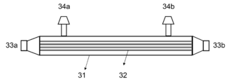
- the structural example of the hollow fiber module used for the cell culture apparatus of this invention is shown.
- the SEM image which observed the surface form of the hollow fiber made from CTA used for the automatic cell culture apparatus which concerns on one Embodiment of this invention is shown.
- 1 is a hollow fiber sectional view observation result.
- 2 is the observation result of the surface form inside the hollow fiber.
- 3 is the observation result of the surface form of the outside of the hollow fiber.
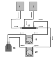
- the structure of the cell culture apparatus used in Example 1 and Comparative Example 2 of the present invention is shown in a simplified manner.
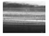
- the observation result of the cell cultured on the hollow fiber inner surface used for the automatic cell culture device concerning one embodiment of the present invention is shown.
- Example 1 The structure of the cell culture apparatus used in the comparative example 1 is simplified and shown.
- One embodiment of the present invention includes the following [1] to [4]: [1] A module using a porous membrane hollow fiber, two openings connected to the inner space of the hollow fiber, and two openings connected to a space formed inside the module and outside the hollow fiber
- Cell culture container [2] having at least one liquid permeable liquid medium storage container [3] channel network connecting the cell culture container and the liquid medium storage container [4] provided in the channel network
- a method of culturing using a cell culturing apparatus comprising means for controlling the supply of liquid to the cell culture container and / or the discharge of liquid from the cell culture container, wherein the inside of the hollow fiber of the cell culture container
- the linear velocity of the liquid medium flowing through the space is controlled to 0.001 mm / min to 5 mm / min
- the linear velocity of the liquid medium flowing through the hollow fiber outer space is controlled to 0.001 mm / min to 5 mm / min, respectively. It is a cell culture method, characterized by.
- the overall size of the cell culture apparatus used in the cell culture method of the present invention is not particularly limited, but is preferably a small one that can be installed in a CO 2 incubator. Since the culture apparatus is small, a plurality of culture apparatuses can be installed in the CO 2 incubator at the same time.
- the weight of the entire culture apparatus is not particularly limited, but is preferably light enough to be installed in a CO 2 incubator.
- the cell culture container used for the cell culture method of the present invention is a module using a porous membrane hollow fiber, and has two openings connected to the inner space (lumen) of the hollow fiber, and an outer space (outer lumen). If it has two opening parts connected to), it will not specifically limit.
- a hollow fiber having a large specific surface area porous membrane hollow fiber
- the module can be miniaturized, and a small culture apparatus that can be installed in a commercially available CO 2 incubator can be realized.
- the hollow fiber module used for the cell culture apparatus of this invention can also be made removable.
- the structure of a module using such a porous membrane hollow fiber is not particularly limited.
- a hollow fiber module is not particularly limited.
- the module case 31 having a shape in which a necessary number of porous membrane hollow fibers 32 are bundled and filled is included.
- the two end conduits 33 are connected to each other by a suitable sealing material (for example, a polyurethane potting agent) so as not to block the hollow portion of the hollow fiber at both ends of the hollow fiber bundle.
- a liquid or the like introduced from one of the conduits 33 is configured to be led out from one end conduit 33 (that is, to flow in one direction) through the hollow fiber lumen.
- the other two side conduits 34 are a space inside the module case 31 and an outer space of the hollow fiber (hereinafter, also simply referred to as “external space side”). Connected and configured such that liquid or the like introduced from one of the side conduits 34 is led out from one side conduit 34 that passes through the outer lumen side of the module 17 (ie, flows in one direction). Has been.
- the size of the hollow fiber module as a cell culture container used in the cell culture method of the present invention can be selected according to the required number of cells. In general, it is preferable to use a larger cell culture container as the required number of cells increases. In addition, when the difference between the amount of cells held and the required amount is large, it may be scaled up as appropriate. For example, when culturing cells on the hollow fiber lumen side, the number of cells is proportional to the membrane area based on the inner diameter of the hollow fiber, so if the initial number of cells is small, such as somatic stem cells, the initial culture is small. A large amount of somatic stem cells can be obtained in the latter half of the culture by scaling up the module step by step using the module.
- the material of the porous membrane hollow fiber used as the culture substrate of the cell culture vessel is not particularly limited as long as it can take a structure that allows a solution or a low-molecular substance to permeate.
- Cellulose materials such as cellulose acetate, cellulose triacetate (CTA), regenerated cellulose, polyethylene, polypropylene, polysulfone, polystyrene, polyvinyl alcohol, polymethyl methacrylate, polyacrylonitrile, fluorine resin, polyamide, polyethersulfone, polyvinylidene fluoride (
- An insoluble carrier having a skeleton structure of a thermoplastic polymer such as PVDF can be preferably used. These derivatives may be the main component.
- the porous membrane hollow fiber used in the present invention may be one obtained by chemically modifying these materials.
- the hollow fiber to be used is preferably subjected to a hydrophilic treatment.
- a hydrophilic treatment By hydrophilizing the hollow fiber, it becomes easy to supply a liquid component such as a culture solution to the cultured cells.
- the method for hydrophilizing the hollow fiber include a method of treating the hollow fiber with a hydrophilic polymer such as ethylene-vinyl alcohol copolymer, glycerin, and ethanol.
- proteins such as collagen, laminin, fibronectin, vitronectin and the like may be coated to improve adhesion to the hollow fiber.
- the size of the porous membrane hollow fiber used in the present invention is not particularly limited, but the inner diameter is preferably 20 to 1000 ⁇ m, more preferably about 50 to 500 ⁇ m.
- the film thickness is not particularly limited, but the hollow fiber may have an appropriate strength and the permeability of the substance may be set within a favorable range, and is preferably about 10 to 200 ⁇ m, for example.
- the pore diameter of the porous membrane hollow fiber used in the present invention is not limited as long as it has a through-hole that allows cells to pass through but does not allow cells to pass through but allows culture medium components such as water, salts, and proteins to pass through.
- it is desirable to have a large pore size with good material exchange efficiency. For example, it is preferably about 0.001 to 5 ⁇ m, and if it has a through hole of about 0.002 to 3 ⁇ m, preferable.
- the hollow fiber module used in the cell culture method of the present invention can be produced, for example, by storing tens to tens of thousands of hollow fiber membranes in a cylindrical container.
- the cell culture is preferably performed on the lumen side.
- seeding is performed by injecting a cell suspension from the end conduit, and after seeding, the cell suspension is switched to the medium and perfused. Incubate for a certain period of time. During this time, it is preferable that the culture medium is also injected into the outer space side from the side conduit and perfused.
- the liquid medium has a role of supplying nutrients necessary for cells and gases such as oxygen and carbon dioxide.
- the hollow fiber module is sterilized by an appropriate method and supplied.
- the sterilization method is not particularly limited, and examples thereof include autoclaving sterilization, gamma ray sterilization, and ethylene oxide gas sterilization.
- the material used for the liquid culture medium storage container used in the cell culture method of the present invention is not particularly limited, but industrially has excellent moldability, can withstand gamma sterilization, and observes the state of the internal culture medium. It is preferable that the material be transparent.
- the gas permeability of the liquid medium storage container is such that the oxygen permeability at 37 ° C. is 200 ⁇ 10 ⁇ 10 cm 3 / (cm 2 ⁇ sec ⁇ cmHg) or more, and the carbon dioxide permeability is 1200 ⁇ 10 ⁇ 10. It is preferably cm 3 / (cm 2 ⁇ sec ⁇ cmHg) or more.
- Such materials include low density polyethylene (oxygen permeability coefficient: 0.4 ⁇ 10 ⁇ 10 to 6 ⁇ 10 ⁇ 10 cm 3 (STP) ⁇ cm / (cm 2 ⁇ sec ⁇ cmHg), carbon dioxide permeability coefficient: 2 ⁇ 10 ⁇ 10 to 30 ⁇ 10 ⁇ 10 cm 3 (STP) ⁇ cm / (cm 2 ⁇ sec ⁇ cmHg)), polyurethane (oxygen transmission coefficient: 1 ⁇ 10 ⁇ 10 to 5 ⁇ 10 ⁇ 10 cm 3 (STP ) ⁇ Cm / (cm 2 ⁇ sec ⁇ cmHg), carbon dioxide permeability coefficient: 5 ⁇ 10 ⁇ 10 to 40 ⁇ 10 ⁇ 10 cm 3 (STP) ⁇ cm / (cm 2 ⁇ sec ⁇ cmHg)), polypropylene (oxygen) Permeability coefficient: 2 ⁇ 10 ⁇ 10 to 50 ⁇ 10 ⁇ 10 cm 3 (STP) ⁇ cm / (cm 2 ⁇ sec ⁇ cmHg), carbon dioxide
- the culture medium storage container can be prepared by adjusting the size and thickness so that the oxygen permeability and the carbon dioxide permeability become the desired values, but both strength and gas permeability are compatible.
- the thickness of the container is preferably 100 to 1000 ⁇ m, more preferably 100 to 500 ⁇ m.
- the form of the liquid medium storage container used in the present invention is not particularly limited, but it is necessary to have at least one opening that can supply the liquid medium to the outside. It is preferable that the opening is configured to be connectable to a flow path to be described later so that the culture medium can be supplied to the hollow fiber module. In addition, the opening can be sealed when not in use and connected to the flow path when the medium is not in contact with the outside so as to prevent evaporation of the liquid medium and reduce the risk of contamination. It is preferable to be configured to be capable of (for example, interconnecting with a sterile connector). Moreover, it is preferable that parts other than the said opening part are comprised so that the culture medium in a container cannot contact the exterior. Examples of such liquid medium storage containers include commercially available culture bags (available from Nipro, Toyo Seikan, etc.), plastic bottles, and the like.
- the configuration is not particularly limited, but includes at least a connection portion between the hollow fiber module and the liquid medium storage container so that the medium can be supplied from the liquid medium storage container to the liquid medium storage container. It needs to be piped.
- the cell culture container has a pipe for supplying the hollow fiber module for seeding cells, a pipe for collecting the cells cultured in the hollow fiber module, and the hollow fiber module. A pipe or the like for discarding the cultured medium may be connected.
- “connection” may be either directly connected or connected through a flow path such as a pipe.
- the material of the channel network used in the cell culture method of the present invention is not particularly limited.
- the gas permeability of the channel network is such that the oxygen permeability at 37 ° C. is 200 ⁇ 10 ⁇ 10 cm 3 / (cm 2 ⁇ sec ⁇ cmHg) or more, and the carbon dioxide permeability is 1200 ⁇ 10 ⁇ 10 cm. 3 / (cm 2 ⁇ sec ⁇ cmHg) or more is preferable.
- Such materials include low density polyethylene (oxygen permeability coefficient: 0.4 ⁇ 10 ⁇ 10 to 6 ⁇ 10 ⁇ 10 cm 3 (STP) ⁇ cm / (cm 2 ⁇ sec ⁇ cmHg), carbon dioxide permeability coefficient: 2 ⁇ 10 ⁇ 10 to 30 ⁇ 10 ⁇ 10 cm 3 (STP) ⁇ cm / (cm 2 ⁇ sec ⁇ cmHg)), polypropylene (oxygen permeability coefficient: 2 ⁇ 10 ⁇ 10 to 50 ⁇ 10 ⁇ 10 cm 3 (STP ) ⁇ Cm / (cm 2 ⁇ sec ⁇ cmHg), carbon dioxide permeability coefficient: 5 ⁇ 10 ⁇ 10 to 20 ⁇ 10 ⁇ 10 cm 3 (STP) ⁇ cm / (cm 2 ⁇ sec ⁇ cmHg)), poly-4-methyl Penten-1 (oxygen permeability coefficient: 2 ⁇ 10 ⁇ 10 to 32 ⁇ 10 ⁇ 10 cm 3 (STP) ⁇ cm / (cm 2 ⁇ sec ⁇ cmH
- the laminated body using these may be sufficient, it is not limited to these.
- the size and thickness of the channel network (tubes) may be adjusted so that the oxygen permeability and carbon dioxide permeability are as desired, but the strength and gas permeability can be improved.
- the thickness of the tube is preferably 0.5 mm to 3 mm. If the gas permeability is too high, bubbles may be generated in the tube, which may impede the flow of the culture medium (medium). It is preferable.
- the form of a method for supplying a liquid such as a cell suspension or a medium is not particularly limited. However, if the liquid medium storage container is a soft one such as a culture bag, the container may be transferred to the container. A method of squeezing the medium by applying a roller is suitable.
- the installation location of the pump is not particularly limited, but it is preferable to install the pump on the discharge side in order to avoid the risk of contamination of liquid when the liquid passes through the pump portion.
- the cell culturing apparatus may be an apparatus further including the following configuration [5]. [5] A CO 2 incubator covering at least a part of [2] and / or [3]
- a liquid medium has a role of supplying nutrients necessary for cells and gases such as oxygen and carbon dioxide.
- gases such as oxygen and carbon dioxide.
- a gas permeable container is used as the liquid medium storage container, and / or a flow channel tube at a portion connecting the liquid medium storage container and the hollow fiber module.
- the CO 2 incubator used in the present invention may cover all the configurations [1] to [4].
- the gas permeable component for example, [2] and / or ([[ 3] or a part other than gas permeable part)
- the gas permeable component for example, a component having no gas permeability in [1] or [3] above, supply and / or discharge of liquid medium, etc. It is not always necessary to cover the inside of the CO 2 incubator with respect to the means for controlling the above.
- the CO 2 incubator used in the present invention is not particularly limited as long as the CO 2 concentration of both the hollow fiber module and the liquid medium storage container can be kept constant, but is preferably sealed.
- the CO 2 incubator used in the present invention has a role as a thermostat as well as maintaining a constant concentration of CO 2 .
- the setting of the CO 2 concentration and temperature is not particularly limited, but it is preferable to set the CO 2 concentration to 5% and the temperature to 37 ° C., respectively. Further, considering this, the CO 2 incubator used in the present invention preferably further covers the configuration of [1].
- CO 2 incubator that can take the means as described above, for example, commercially available products such as those manufactured by Panasonic, Thermo Fisher Scientific, and Yamato Scientific can be used.
- Adhesive animal cell is suitable.
- the origin of the cell is not particularly limited, and those derived from any animal such as human, mouse, rat and the like can be used.
- Adhesive animal cells can target both primary cultured cells and established cells. It does not ask
- it may be a cell line or a primary cell. Examples include cell lines such as NIH3T3 cells, Hela cells, COS cells, HEK cells, L929 cells, Daudi cells, Jurkat cells, KG-1a cells, and various hybridoma cell lines.
- primary cells such as nerve cells, keratinocytes, fibroblasts, lung epithelial cells, hepatocytes, blood cells and the like can be mentioned.
- stem cells and progenitor cells such as ES cells, hematopoietic stem cells, hepatic stem cells, and mesenchymal stem cells may be used. These cells may be cells into which a foreign gene has been introduced before culturing, or may be cells that have been stimulated and processed in advance with stimulating factors such as antibodies and ligands.
- means for seeding cells is not particularly limited.
- a method using the liquid medium storage container can be mentioned. This method is a method in which a solution containing cells to be seeded is placed in the liquid medium storage container, and poured into the hollow fiber module as a cell culture container via a connecting flow path for perfusion. After seeding, the liquid medium storage container may be switched to a medium containing no medium and perfused for culturing.
- a culture bag is used for a liquid medium storage container
- a solution containing cells and medium to be seeded is placed in the culture bag and set in a cell culture device, and then the solution is transferred to the hollow fiber module to start seeding.
- the culture may be performed by switching to a culture bag containing only the medium.
- This method is preferably used when the amount of the solution containing cells to be seeded is large.
- a pipe that allows the solution to flow into the hollow fiber module by injection using a syringe or the like may be separately configured.
- Cell culture in the cell culture device used in the cell culture method of the present invention can be performed by continuing to send the medium to the cell culture container (preferably in a CO 2 incubator).
- the liquid medium has a role of supplying the cells with nutrients necessary for the cells and gases such as oxygen and carbon dioxide.
- the hollow fiber module is used as a cell culture container of a cell culture device.
- the supply of the medium to the hollow fiber module requires two routes on the lumen side and the lumen side.
- liquid medium storage containers may be used separately on the lumen side and the outer lumen side in supplying the medium, or the medium is supplied from one container to both the lumen side and the outer lumen side. Also good.
- the medium composition on the lumen side and the medium composition on the outer lumen side may be the same or different, but are preferably the same composition.
- the medium used for the culture is determined according to the type of the cultured cell, and may be any medium that is usually used as the medium for the cell.
- the culture method of the present invention can also be used for serum-free culture.
- the flow rate on the lumen side and the flow rate on the outer lumen side may be the same or different, but in the method of the present invention, the linear velocity of the liquid medium flowing through the hollow fiber lumen side is set to 0.001 mm / It is necessary to control the linear velocity of the liquid medium flowing on the outer side of the hollow fiber to 0.001 mm / min to 5 mm / min.
- the flow rate of the medium during the culture is not particularly limited as long as it is within the above range, but a flow rate suitable for cell growth is preferable. From this viewpoint, it is preferable that the inner cavity side is 0.002 to 5 mm / min and the outer cavity side is 0.002 to 5 mm / min.
- the inner cavity side is 0.002 to 4 mm / min and the outer cavity side is 0.002 to 4 mm / min.
- the flow rate of a culture medium is preferably adjusted based on measurement results such as the concentration of glucose and lactate in the medium.
- the medium flow rate is adjusted according to the size of the module.
- the flow of the medium from the liquid medium storage container to the hollow fiber module is preferably unidirectional.
- one direction means that the route from introduction of the culture medium to the hollow fiber module is always in the same direction.
- a so-called circulation type in which the medium once derived from the hollow fiber module is introduced again from the introduction port may be used.
- at least one of the inner side and the outer side of the hollow fiber may be a circulation type, or both of them may be a circulation type.
- the hollow fiber module which is a cell culture vessel, may be shaken or rolled. It is preferable to perform such an operation in that the cells can be uniformly seeded in the hollow fiber module, the cells can be removed when bubbles are generated, and the nutrients of the medium are evenly distributed to the cultured cells. .
- the cell culturing apparatus used in the cell culturing method of the present invention may include means for monitoring the components and concentrations of cellular metabolites such as pH, glucose, lactate, oxygen, etc. over time, and analysis means.
- a sensor for detection can be included.
- the sensor can be attached at any position on the inner tube of the hollow fiber or the tube of the outer port of the hollow fiber.
- the culture medium can be collected periodically by attaching a fraction collector to the inside of the hollow fiber or the outlet of the outside of the hollow fiber.
- the concentration of glucose or lactate in the medium can be used as an index for adjusting the flow rate of the medium because it depends on cell proliferation. For example, when the glucose concentration is decreased, the cells are growing, so that nutrients are supplied to the cells. Therefore, the flow rate of the medium can be increased to provide an environment in which the cells are more likely to grow.
- the cell culture device used in the cell culture method of the present invention includes a work controller (work panel) for controlling the above operations and processes and for the convenience of monitoring and the like. May be.
- the means for collecting the cells in the cell culture device used in the cell culture method of the present invention is not particularly limited.
- divalent cation-free phosphate buffered saline PBS
- PBS divalent cation-free phosphate buffered saline
- the PBS is further perfused for a fixed time, and then the PBS is removed and a protease such as trypsin is filled inside and outside the hollow fiber.
- the cultured cells are detached from the hollow fiber lumen by trypsin treatment and collected from the hollow fiber module.
- the cell culture device used in the cell culture method of the present invention may further have a cell collection container and a waste liquid collection container as necessary.
- the form of the cell collection container is not particularly limited.
- a glass bottle, a plastic bottle, a culture bag, etc. are mentioned.
- the form of the waste liquid collection container is not particularly limited.
- a glass bottle, a plastic bottle, a culture bag, etc. are mentioned.
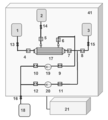
- FIG. 1 shows one configuration example of a cell culture apparatus used in the cell culture method of the present invention.
- reference numerals 1 and 2 denote gas-permeable liquid medium storage containers (such as culture bags), respectively.
- the liquid medium storage container 1 via the sterile connection connector 13 and the valve 4, to the end conduit 33a of the cell culture container 17 (in the embodiment, a hollow fiber module.
- FIG. 2 shows a configuration example thereof)
- the flow path is connected so that the medium contained in the liquid medium storage container 1 can be transferred to the lumen side of the cell culture container 17.
- a flow path is connected to the side conduit 34 a of the cell culture container (hollow fiber module in the embodiment) 17 via the aseptic connection connector 14 and the valve 5.
- the medium contained in the container 2 can be transferred to the outer cavity side of the cell culture container 17. From the lumen side of the cell culture container 17, a flow path is further connected to the waste liquid collection container 18 via the valve 7, the valve 11, the liquid feeding pump 20, the valve 12, and the aseptic connection connector 16. The medium that has passed through can be discarded. In addition, supply of liquid (medium etc.) from the liquid medium storage container 1 to the cell culture container 17 and / or discharge of the liquid from the cell culture container by the liquid feed pump 20 provided in the flow path, Furthermore, it is possible to control the flow rate or the like in discarding the liquid.
- a flow path is further connected to the waste liquid collection container 18 via the valve 6, the valve 9, the liquid feeding pump 19, the valve 10, and the aseptic connection connector 16.
- the medium that has passed through the container 17 can be discarded.
- supply of liquid (medium etc.) from the liquid medium storage container 2 to the cell culture container 17 and / or discharge of the liquid from the cell culture container by the liquid feeding pump 19 provided in the flow path Furthermore, it is possible to control the flow rate or the like in discarding the liquid.
- the cell collection container 3 includes a valve 8, a sterile connection connector that branches from the lumen side of the cell culture container 17 via the valve 7 and further branches off from the waste system flow path on the lumen side.
- the flow path is connected via 15 so that the cells cultured in the cell culture vessel 17 can be collected.
- the flow path network may be further provided with a pump or the like to collect cells.
- the cell may be collected by removing the cell culture container 17 from the cell culture device. In this case, there is no configuration from the branch of the waste-side flow path on the lumen side to the cell collection container 3. Good.
- 41 is a CO 2 incubator. In FIG. 1, most of the above-described configuration is covered.
- reference numeral 21 denotes a work controller (work panel), which may be set for convenience such as performing the above-described operations and processes and monitoring.
- the hollow fiber module for culture used in each example described later was prepared as follows.
- the material of the hollow fiber to be used is shown in each example.
- both ends are fixed to the module case with a polyurethane potting agent so as not to block the hollow part of the hollow fiber.
- FIG. 4 shows a simplified configuration of the cell culture apparatus used in this example.
- a hollow fiber module (17 in FIG. 4) (hollow fiber: manufactured by CTA, manufactured by Toyobo Co., Ltd.) coated with fibronectin (manufactured by Corning) on the day before cell seeding was used.
- the hollow fiber had an inner diameter of 200 ⁇ m, an outer diameter of 250 ⁇ m, and a film thickness of 25 ⁇ m.
- SEM image surface form observation result of the hollow fiber made from CTA is shown.
- 1 is a hollow fiber cross-sectional view observation result
- 2 is a hollow fiber inner surface form observation result
- 3 is a hollow fiber outer surface form observation result.
- the mesenchymal stem cells used were primary cells purchased from Takara Bio Inc.
- the cell seeding density was 1900 cells / cm 2 .
- the flow rate of the medium was 0.33 mm / min on the hollow fiber lumen side and 3.46 mm / min on the hollow fiber outer lumen side.
- a gas-permeable culture bag 1L (manufactured by Nipro Co., Ltd.) (1 (luminal side) and 2 (external side) in FIG. 4) is provided in the liquid medium storage container, and a gas-permeable silicone is provided in the channel network.
- a tube was used.
- GlutaMAX manufactured by Life Technologies
- a total of two Perista Biomini pumps (manufactured by Ato) (19 (luminal side) and 20 (external side) in FIG. 4) were used for hollow fiber inner perfusion and outer perfusion. .
- the cells were cultured at 37 ° C. for 7 days in a CO 2 incubator.
- the medium supply method was unidirectional on both the hollow fiber lumen side and the hollow fiber outer lumen side.
- Mesenchymal stem cells were seeded inside the hollow fiber (the number of seeded cells was 3.0 ⁇ 10 5 cells / module) and allowed to stand for 2 days, and then perfusion inside the hollow fiber was started. After 7 days of culture, the medium perfusion was stopped and the cells grown in the hollow fiber module were collected.
- FIG. 5 shows the observation results of the cells cultured on the hollow fiber lumen side. It was confirmed that cells adhered and proliferated on the hollow fiber lumen side.
- FIG. 6 shows a simplified configuration of the cell culture device used in this comparative example.
- Mesenchymal stem cells were seeded inside the hollow fiber similar to that used in Example 1, and after standing for 2 days, perfusion inside the hollow fiber was started.
- the mesenchymal stem cells used were primary cells purchased from Takara Bio Inc.
- the cell seeding density was 1900 cells / cm 2 .
- the flow rate of the medium was 0.33 mm / min on the hollow fiber lumen side and 3.46 mm / min on the hollow fiber outer lumen side.
- a gas-impermeable glass bottle manufactured by Asahi Glass Co., Ltd.
- 51 luminal side
- 52 exitternal lumen side
- a gas-permeable glass bottle is used for the channel network.
- Tube made of silicone
- Reference numeral 53 denotes a gas exchange tube (silicone tube in this comparative example).
- the length of the silicone tube was 1.5 m.
- ⁇ -MEM manufactured by Life Technologies
- Perto Biominipumps (56 (inner lumen side) and 57 (external lumen side) in FIG. 6) manufactured by ATTO Corporation were used.
- the cells were cultured at 37 ° C. for 7 days in a CO 2 incubator.
- the medium supply method was unidirectional on both the hollow fiber lumen side and the hollow fiber outer lumen side.
- Mesenchymal stem cells were seeded inside the hollow fiber and allowed to stand for 2 days, and then perfusion inside the hollow fiber was started. After 7 days of culture, the medium perfusion was stopped and the cells grown in the hollow fiber module were collected. At the time of cell recovery, a cell dissociation reagent, 0.25% trypsin solution (manufactured by Life Technologies) was used.
- FIG. 4 shows a simplified configuration of the cell culture device used in this comparative example.
- a hollow fiber module (17 in FIG. 4) (hollow fiber: manufactured by CTA, manufactured by Toyobo Co., Ltd.) coated with fibronectin (manufactured by Corning) on the day before cell seeding was used.
- the hollow fiber had an inner diameter of 200 ⁇ m, an outer diameter of 250 ⁇ m, and a film thickness of 25 ⁇ m.
- SEM image surface form observation result of the hollow fiber made from CTA is shown.
- the mesenchymal stem cells used were primary cells purchased from Takara Bio Inc.
- the cell seeding density was 1900 cells / cm 2 .
- the flow rate of the medium was 20 mm / min on the hollow fiber lumen side and 30 mm / min on the hollow fiber outer lumen side.
- a gas-permeable culture bag 1L (manufactured by Nipro Co., Ltd.) (1 (lumen side) and 2 (external side) in FIG. 4) is used for the liquid medium storage container, and a silicone tube is used for the channel network.
- GlutaMAX (manufactured by Life Technologies) containing 10% serum was used as the medium.
- a total of two Perista Biomini pumps manufactured by Ato
- the cells were cultured at 37 ° C. for 7 days in a CO 2 incubator.
- the medium supply method was unidirectional on both the hollow fiber lumen side and the hollow fiber outer lumen side.
- Mesenchymal stem cells were seeded inside the hollow fiber (the number of seeded cells was 3.0 ⁇ 10 5 cells / module) and allowed to stand for 2 days, and then perfusion inside the hollow fiber was started. After 7 days of culture, the medium perfusion was stopped and the cells grown in the hollow fiber module were collected.
- a cell dissociation reagent, 0.25% trypsin solution manufactured by Life Technologies
- Table 1 summarizes the results of the cell culture experiments of Example 1 and Comparative Examples 1 and 2.
- a gas-permeable culture bag for the liquid medium storage container (medium supply container)
- the cell growth rate was improved as compared with the case where a glass bottle without gas permeability was used.
- the cell growth rate was significantly lower than that of the present invention even when a gas exchange tube was connected.
- As a gas exchange method in the method using a gas permeable silicone tube, even if the length of the tube is 1.5 m is not sufficient in order to sufficiently perform the gas exchange.
- the linear velocity of the liquid medium flowing through the hollow fiber lumen side is 0.001 mm / min to 5 mm / min
- the linear velocity of the liquid medium flowing through the hollow fiber lumen side is 0.001 mm / min to 5 mm / min.
- the cell proliferation rate improved by controlling each.
- the present invention it is possible to provide a cell culture apparatus that can culture various cells including stem cells in a safe, simple and highly efficient manner as compared with conventional methods.
- Liquid medium storage container 3 having gas permeability 3 Cell collection container 4 to 12 Valve 13 to 16 Aseptic connection connector 17 Cell culture container (hollow fiber module in the embodiment) 18 Waste liquid collection containers 19 and 20 Liquid feed pump 21 Work controller (work panel) 31 Module Case 32 Porous Membrane Hollow Fiber 33 End Conduit 34 Side Conduit 41 CO 2 Incubator 51, 52 Liquid Medium Storage Container (Glass Bottle) Not Gas Permeable 53 Gas exchange tube 54 Hollow fiber module 55 Waste liquid collection container 56, 57 Liquid feed pump
Landscapes
- Health & Medical Sciences (AREA)
- Life Sciences & Earth Sciences (AREA)
- Engineering & Computer Science (AREA)
- Organic Chemistry (AREA)
- Chemical & Material Sciences (AREA)
- Biomedical Technology (AREA)
- Bioinformatics & Cheminformatics (AREA)
- Wood Science & Technology (AREA)
- Zoology (AREA)
- Genetics & Genomics (AREA)
- Biotechnology (AREA)
- Biochemistry (AREA)
- Microbiology (AREA)
- General Engineering & Computer Science (AREA)
- General Health & Medical Sciences (AREA)
- Cell Biology (AREA)
- Virology (AREA)
- Sustainable Development (AREA)
- Apparatus Associated With Microorganisms And Enzymes (AREA)
- Micro-Organisms Or Cultivation Processes Thereof (AREA)
Abstract
【課題】雑多な細胞集団の中に極少数しか存在しない間葉系幹細胞などの各種細胞を、従来法と比較して、安全、簡便かつ高効率に培養することのできる細胞培養装置を提供することを目的とする。 【解決手段】[1]細胞培養容器、[2]ガス透過性を有する液体培地貯留容器、[3]前記細胞培養容器と前記液体培地貯留容器とを接続する流路網、[4]前記流路網に設けられ液体の供給および/または排出を制御する手段、を含む細胞培養装置。
Description
本発明は、細胞を培養するための中空糸モジュールを用いた細胞培養方法に関する。
幹細胞は臓器や組織を形成し得る細胞であり、成体であってもほとんどの臓器や組織に存在していると考えられている。幹細胞のうち胚細胞(ES細胞)は万能細胞であり全ての組織や臓器に分化する能力を持っている。一方、体性幹細胞は全ての臓器や組織に分化できるわけでなく特定の組織や臓器に分化する。ヒト組織から採取できる体性幹細胞は患者自身から採取でき、拒絶反応の恐れがないため再生医療に対する移植材料として注目されている。
ヒトにおける体性幹細胞は現在までに間葉系幹細胞、造血幹細胞、神経幹細胞、心筋幹細胞、膵幹細胞、皮膚幹細胞、骨髄幹細胞、網膜幹細胞、角膜内皮幹細胞などが知られている。しかし、幹細胞が組織に含まれる割合は極めて微量である。
体外で培養した体性幹細胞を、同一人又は他人の治療に使用するという再生医療が発達し、一部では実用化され始めている。このような再生医療に於いては、人体から採取した少量の細胞を体外にて、移植に必要な細胞数にまで増やす作業が必要となる。また、体外にて培養する際は、培養細胞の汚染を防止することが重要である。
再生医療に用いる細胞の培養は、現在は、細胞プロセシングセンタ(Cell Processing Center:CPC)という細胞培養用クリーンルームの中で、GMP(Good Manufacturing Practice)に準拠して行われている(非特許文献1)。
平成14年度厚生労働科学研究費補助金総括・分担研究報告書「先端医療センター等における細胞治療・再生医療開発のためのGMP準拠細胞プロセッシング指針の作成に関する研究」
この場合の課題は、幹細胞の培養は技術者の手によって行われるために、患者1名分の細胞の調製に対して労力とコストが非常にかかるという点と、手動で操作することによる生物学的汚染リスクがあるという点である。
そのため、再生医療の実用化には安全で低コストの幹細胞培養が求められており、インキュベーション、培地交換操作、継代操作等を細胞培養完了まで繰り返して自動で行う自動化装置の必要性が検討されている。
本発明者は、上記課題を解決するために鋭意検討した結果、以下に示す手段により上記課題を解決できることを見出し、本発明に到達した。
すなわち、本発明は、以下の構成からなる。
1.以下の[1]から[4]の構成:
[1]多孔性膜中空糸を用いたモジュールであって、前記中空糸の内側空間と接続する2つの開口部と、前記モジュールの内側かつ前記中空糸の外側からなる空間と接続する2つの開口部を有する細胞培養容器
[2]少なくとも1つのガス透過性を有する液体培地貯留容器
[3]前記細胞培養容器と前記液体培地貯留容器とを接続する流路網
[4]前記流路網に設けられ、前記細胞培養容器への液体の供給および/または前記細胞培養容器からの液体の排出を制御する手段
を含む細胞培養装置を用いた培養方法であって、前記細胞培養容器の中空糸の内側空間を流れる液体培地の線速度を0.001mm/min~5mm/minに、かつ中空糸外側空間を流れる液体培地の線速度を0.001mm/min~5mm/minに、それぞれ制御することを特徴とする細胞培養方法。
2.前記細胞培養装置が、さらに以下の[5]の構成を含む、1に記載の細胞培養方法。
[5]前記[2]および/または前記[3]の少なくとも一部をカバーするCO2インキュベーター
3.前記流路網にガス透過性の流路管を用いる、1または2に記載の細胞培養方法。
4.前記細胞培養装置において、前記液体培地貯留容器から前記細胞培養容器への培地の流れが一方向である、1から3のいずれかに記載の細胞培養方法。
5.前記細胞培養容器が着脱可能である、1から4のいずれかに記載の細胞培養方法。
6.前記中空糸が細胞接着性タンパク質でコーティングされている、1から5のいずれかに記載の細胞培養方法。
1.以下の[1]から[4]の構成:
[1]多孔性膜中空糸を用いたモジュールであって、前記中空糸の内側空間と接続する2つの開口部と、前記モジュールの内側かつ前記中空糸の外側からなる空間と接続する2つの開口部を有する細胞培養容器
[2]少なくとも1つのガス透過性を有する液体培地貯留容器
[3]前記細胞培養容器と前記液体培地貯留容器とを接続する流路網
[4]前記流路網に設けられ、前記細胞培養容器への液体の供給および/または前記細胞培養容器からの液体の排出を制御する手段
を含む細胞培養装置を用いた培養方法であって、前記細胞培養容器の中空糸の内側空間を流れる液体培地の線速度を0.001mm/min~5mm/minに、かつ中空糸外側空間を流れる液体培地の線速度を0.001mm/min~5mm/minに、それぞれ制御することを特徴とする細胞培養方法。
2.前記細胞培養装置が、さらに以下の[5]の構成を含む、1に記載の細胞培養方法。
[5]前記[2]および/または前記[3]の少なくとも一部をカバーするCO2インキュベーター
3.前記流路網にガス透過性の流路管を用いる、1または2に記載の細胞培養方法。
4.前記細胞培養装置において、前記液体培地貯留容器から前記細胞培養容器への培地の流れが一方向である、1から3のいずれかに記載の細胞培養方法。
5.前記細胞培養容器が着脱可能である、1から4のいずれかに記載の細胞培養方法。
6.前記中空糸が細胞接着性タンパク質でコーティングされている、1から5のいずれかに記載の細胞培養方法。
本発明の細胞培養方法で用いる多孔性膜中空糸を用いたモジュールは、前記中空糸内側の空間と前記中空糸の外側の空間にそれぞれ液体培地を流せるよう構成されており、前記それぞれの空間に液体培地を流す流速を適宜設定することによって、雑多な細胞集団の中に極少数しか存在しない間葉系幹細胞などの各種細胞を、従来法と比較して、安全、簡便かつ高効率に培養することを可能とする。
本発明の実施態様の一つは、以下の[1]から[4]の構成:
[1]多孔性膜中空糸を用いたモジュールであって、前記中空糸の内側空間と接続する2つの開口部と、前記モジュールの内側かつ前記中空糸の外側からなる空間と接続する2つの開口部を有する細胞培養容器
[2]少なくとも1つのガス透過性を有する液体培地貯留容器
[3]前記細胞培養容器と前記液体培地貯留容器とを接続する流路網
[4]前記流路網に設けられ、前記細胞培養容器への液体の供給および/または前記細胞培養容器からの液体の排出を制御する手段
を含む細胞培養装置を用いた培養方法であって、前記細胞培養容器の中空糸の内側空間を流れる液体培地の線速度を0.001mm/min~5mm/minに、かつ中空糸外側空間を流れる液体培地の線速度を0.001mm/min~5mm/minに、それぞれ制御することを特徴とする細胞培養方法である。
[1]多孔性膜中空糸を用いたモジュールであって、前記中空糸の内側空間と接続する2つの開口部と、前記モジュールの内側かつ前記中空糸の外側からなる空間と接続する2つの開口部を有する細胞培養容器
[2]少なくとも1つのガス透過性を有する液体培地貯留容器
[3]前記細胞培養容器と前記液体培地貯留容器とを接続する流路網
[4]前記流路網に設けられ、前記細胞培養容器への液体の供給および/または前記細胞培養容器からの液体の排出を制御する手段
を含む細胞培養装置を用いた培養方法であって、前記細胞培養容器の中空糸の内側空間を流れる液体培地の線速度を0.001mm/min~5mm/minに、かつ中空糸外側空間を流れる液体培地の線速度を0.001mm/min~5mm/minに、それぞれ制御することを特徴とする細胞培養方法である。
本発明の細胞培養方法に用いる細胞培養装置全体の大きさについては、特に制限はないが、好ましくはCO2インキュベーター内に設置可能な小型なものである。培養装置は小型のため、複数台同時にCO2インキュベーター内に設置することも可能である。また、培養装置全体の重量については、特に制限はないが、好ましくはCO2インキュベーター内に設置可能な程度の軽量なものである。
(細胞培養容器)
本発明の細胞培養方法に用いる細胞培養容器は、多孔性膜中空糸を用いたモジュールであって、前記中空糸の内側空間(内腔)と接続する2つの開口部と、外側空間(外腔)と接続する2つの開口部を有するものであれば、特に限定されない。比表面積の大きい中空糸(多孔性膜中空糸)を培養基材として用いることによりモジュールを小型化でき、市販のCO2インキュベーター内に設置することが可能な小型培養装置を実現することができる。なお、本発明の細胞培養装置に用いる中空糸モジュールは、着脱可能にすることもできる。
本発明の細胞培養方法に用いる細胞培養容器は、多孔性膜中空糸を用いたモジュールであって、前記中空糸の内側空間(内腔)と接続する2つの開口部と、外側空間(外腔)と接続する2つの開口部を有するものであれば、特に限定されない。比表面積の大きい中空糸(多孔性膜中空糸)を培養基材として用いることによりモジュールを小型化でき、市販のCO2インキュベーター内に設置することが可能な小型培養装置を実現することができる。なお、本発明の細胞培養装置に用いる中空糸モジュールは、着脱可能にすることもできる。
このような多孔性膜中空糸を用いたモジュール(以下、中空糸モジュールとも称する)の構成は特に限定されないが、例えば図2に示すように、4つの開口部(端部導管および側部導管)を有するモジュールケース31に多孔性膜中空糸32が適宜必要な本数束ねられて充填されている形態が挙げられる。この形態において、2つの端部導管33は、それぞれ中空糸束の両端において中空糸の中空部を閉塞しないように適当なシール材(例えば、ポリウレタン系ポッティング剤)により接続されており、前記端部導管33の一方から導入された液体などが中空糸内腔を通ってもう一方の端部導管33から導出される(すなわち、一方向に流れる)ように構成されている。一方、前記開口部のうち、他の2つの側部導管34は、前記モジュールケース31の内側であってかつ前記中空糸の外腔である空間(以下、単に「外腔側」とも呼ぶ)と接続しており、前記側部導管34の一方から導入された液体などがモジュール17の外腔側を通ってもう一方の側部導管34から導出される(すなわち、一方向に流れる)ように構成されている。
このようなモジュールとしては他にも種々の形態が開示されていて、例えば、特開2005-333945号公報や特開2007-202430号公報などに記載のものが挙げられる。
本発明の細胞培養方法に用いる細胞培養容器としての中空糸モジュールの大きさは、必要細胞数に応じて、選択することができる。一般に、必要細胞数が多いほど大きな細胞培養容器を用いることが好ましい。また、細胞の保有量と必要量との差が大きい場合は適宜段階的にスケールアップしても良い。例えば、中空糸内腔側で細胞を培養する際は、細胞数は、中空糸内径基準の膜面積に比例するので、体性幹細胞のように初期の細胞数が少ない場合は、培養初期は小型モジュールを用い、段階的にモジュールをスケールアップすることにより、培養後半過程において、大量の体性幹細胞を得ることができる。
細胞培養容器の培養基材として用いる多孔性膜中空糸の素材については、溶液や低分子の物質を透過させるような構造をとることができるものであれば、特に限定されるものではなく、例えば、セルロースアセテート、セルローストリアセテート(CTA)、再生セルロースなどのセルロース系素材、ポリエチレン、ポリプロピレン、ポリスルホン、ポリスチレン、ポリビニルアルコール、ポリメチルメタクリレート、ポリアクリロニトリル、フッ素系樹脂、ポリアミド、ポリエーテルスルホン、ポリフッ化ビニリデン(PVDF)等の熱可塑性高分子による骨格構造を有する不溶性担体が好適に利用できる。また、これらの誘導体が主成分であっても良い。また、本発明で使用する多孔性膜中空糸は、さらにこれらの素材に化学的に修飾を加えたものであっても良い。例えば、使用する中空糸は、親水化処理されていることが好ましい。中空糸を親水化処理することにより、培養細胞への培養液等の液体成分の供給が容易になる。中空糸を親水化処理する方法としては、例えば、中空糸をエチレン-ビニルアルコール共重合体等の親水性高分子や、グリセリン、エタノールで処理する方法が挙げられる。また、使用する細胞に応じて、中空糸への接着向上のため、コラーゲンやラミニン、フィブロネクチン、ビトロネクチン等のタンパク質をコーティングしても良い。
本発明に用いる多孔性膜中空糸の大きさについても特に制限はないが、内径は好ましくは20~1000μm、より好ましくは50~500μm程度のものが利用される。膜厚についても、特に制限はないが、中空糸が適度の強度を保ち、かつ物質の透過性も良好な範囲で設定すればよく、例えば10~200μm程度が好ましい。
本発明に用いる多孔性膜中空糸の孔径は、細胞は通過させないが水、塩類、蛋白質などの培養液成分は通過させる通孔を有するものであればよい。細胞の培養を考慮すると物質交換の効率のよい大きな孔径を有する方が望ましく、例えば、0.001~5μm程度であることが好ましく、0.002~3μm程度の通孔を有するものであればさらに好ましい。
本発明の細胞培養方法に用いる中空糸モジュールは、例えば、筒状容器に数十~数万本の中空糸膜を格納することにより作製することができる。
前記中空糸モジュールを用いる場合、細胞培養は内腔側で行うことが好ましい。たとえば、内腔側にて、細胞を培養する際は、細胞縣濁液を端部導管より注入することにより播種し、播種終了後、細胞懸濁液を培地に切り換えて灌流させ、内腔側にて一定期間培養を行う。この間、同時に、外腔側へも、培地を側部導管より注入し灌流させることが好ましい。液体培地は細胞に必要な養分や酸素・二酸化炭素などのガスを供給する役割を有する。培養期間中、ガス交換および細胞への栄養供給、老廃物除去のため、内腔側、外腔側ともに、培地を一方向に供給し続けることが好ましい。その際、後述のポンプ等を用いることにより、適切な速度で循環させたり、供給・排出したりすることができる。
前記中空糸モジュールは、適切な方法で滅菌し、供給される。滅菌方法については、特に制限はないが、例えば、加圧加熱滅菌、ガンマ線滅菌、エチレンオキサイドガス滅菌等が挙げられる。
培養容器に中空糸モジュールを用いることにより、細胞へ常に新鮮な培地を供給することができ、培養基材にシャーレや多段フラスコ等を用いる際に必要な交換作業は不要となり、作業者の拘束時間を減らすことができる。
(液体培地貯留容器)
本発明の細胞培養方法に用いる液体培地貯留容器に用いられる素材は、特に限定されないが、工業的に成形加工性に優れ、ガンマ線滅菌に耐えうるものであり、かつ内部の培地の様子を観察することができる透明性の材料であることが好ましい。具体的には、液体培地貯留容器のガス透過度は、37℃における酸素透過度が200×10-10cm3/(cm2・sec・cmHg)以上、二酸化炭素透過度が1200×10-10cm3/(cm2・sec・cmHg)以上であることが好ましい。このような材料としては、低密度ポリエチレン(酸素透過係数:0.4×10-10~6×10-10cm3(STP)・cm/(cm2・sec・cmHg)、二酸化炭素透過係数:2×10-10~30×10-10cm3(STP)・cm/(cm2・sec・cmHg))、ポリウレタン(酸素透過係数:1×10-10~5×10-10cm3(STP)・cm/(cm2・sec・cmHg)、二酸化炭素透過係数:5×10-10~40×10-10cm3(STP)・cm/(cm2・sec・cmHg))、ポリプロピレン(酸素透過係数:2×10-10~50×10-10cm3(STP)・cm/(cm2・sec・cmHg)、二酸化炭素透過係数:5×10-10~20×10-10cm3(STP)・cm/(cm2・sec・cmHg))、ポリ4メチルペンテン-1(酸素透過係数:2×10-10~32×10-10cm3(STP)・cm/(cm2・sec・cmHg)、二酸化炭素透過係数:15×10-10~72×10-10cm3(STP)・cm/(cm2・sec・cmHg))、シリコーン(酸素透過係数:450×10-10~650×10-10cm3(STP)・cm/(cm2・sec・cmHg)、二酸化炭素透過係数:2500×10-10~3200×10-10cm3(STP)・cm/(cm2・sec・cmHg))などが挙げられる。また、これらを使用した積層体であってもよいが、これらに限定されるものではない。これらの材料を用いて、酸素透過度および二酸化炭素透過度が所望の値になるように、大きさや厚みを調整して培養液貯留容器を作製すればよいが、強度やガス透過性を両立する上で、容器の厚みは100~1000μmが好ましく、100~500μmがより好ましい。
本発明の細胞培養方法に用いる液体培地貯留容器に用いられる素材は、特に限定されないが、工業的に成形加工性に優れ、ガンマ線滅菌に耐えうるものであり、かつ内部の培地の様子を観察することができる透明性の材料であることが好ましい。具体的には、液体培地貯留容器のガス透過度は、37℃における酸素透過度が200×10-10cm3/(cm2・sec・cmHg)以上、二酸化炭素透過度が1200×10-10cm3/(cm2・sec・cmHg)以上であることが好ましい。このような材料としては、低密度ポリエチレン(酸素透過係数:0.4×10-10~6×10-10cm3(STP)・cm/(cm2・sec・cmHg)、二酸化炭素透過係数:2×10-10~30×10-10cm3(STP)・cm/(cm2・sec・cmHg))、ポリウレタン(酸素透過係数:1×10-10~5×10-10cm3(STP)・cm/(cm2・sec・cmHg)、二酸化炭素透過係数:5×10-10~40×10-10cm3(STP)・cm/(cm2・sec・cmHg))、ポリプロピレン(酸素透過係数:2×10-10~50×10-10cm3(STP)・cm/(cm2・sec・cmHg)、二酸化炭素透過係数:5×10-10~20×10-10cm3(STP)・cm/(cm2・sec・cmHg))、ポリ4メチルペンテン-1(酸素透過係数:2×10-10~32×10-10cm3(STP)・cm/(cm2・sec・cmHg)、二酸化炭素透過係数:15×10-10~72×10-10cm3(STP)・cm/(cm2・sec・cmHg))、シリコーン(酸素透過係数:450×10-10~650×10-10cm3(STP)・cm/(cm2・sec・cmHg)、二酸化炭素透過係数:2500×10-10~3200×10-10cm3(STP)・cm/(cm2・sec・cmHg))などが挙げられる。また、これらを使用した積層体であってもよいが、これらに限定されるものではない。これらの材料を用いて、酸素透過度および二酸化炭素透過度が所望の値になるように、大きさや厚みを調整して培養液貯留容器を作製すればよいが、強度やガス透過性を両立する上で、容器の厚みは100~1000μmが好ましく、100~500μmがより好ましい。
本発明に用いる液体培地貯留容器の形態は特に限定されないが、液体培地を外部に供給できる開口部を少なくとも1つ有している必要がある。前記開口部は、培地を前記中空糸モジュールに供給できるように、後述の流路に接続可能に構成されていることが好ましい。また、液体培地の蒸発を防止し、また、汚染の危険性を低減できるように、前記開口部は、未使用時は密栓でき、かつ使用時は培地が外部と接触できない状態で流路に接続(例えば、無菌コネクターによる相互接続)できるよう構成されていることが好ましい。また、前記開口部以外の部分は、容器内の培地が外部と接触できないよう構成されていることが好ましい。このような液体培地貯留容器としては、例えば、市販の培養バッグ(ニプロ社製、東洋製罐社製のものなどが入手できる)、プラスチック製ボトルなどが挙げられる。
(流路網)
本発明の細胞培養方法において、細胞培養容器としての前記中空糸モジュールにはいくつかの流路(流路網)が接続されている。その構成(配管)は特に限定されないが、少なくとも前記中空糸モジュールと前記液体培地貯留容器との接続部分を含み、前記液体培地貯留容器から前記液体培地貯留容器への培地の供給が可能なように配管されている必要がある。このほか、前記細胞培養容器には、細胞を播種するために前記中空糸モジュールに供給するための配管、前記中空糸モジュールで培養された細胞を回収するための配管や、前記中空糸モジュールを通過した培地を廃棄するための配管などが接続されていてもよい。なお、本明細書において「接続」とは、直接繋がっている場合、および配管などの流路を介して繋がっている場合のいずれであってもよい。
本発明の細胞培養方法において、細胞培養容器としての前記中空糸モジュールにはいくつかの流路(流路網)が接続されている。その構成(配管)は特に限定されないが、少なくとも前記中空糸モジュールと前記液体培地貯留容器との接続部分を含み、前記液体培地貯留容器から前記液体培地貯留容器への培地の供給が可能なように配管されている必要がある。このほか、前記細胞培養容器には、細胞を播種するために前記中空糸モジュールに供給するための配管、前記中空糸モジュールで培養された細胞を回収するための配管や、前記中空糸モジュールを通過した培地を廃棄するための配管などが接続されていてもよい。なお、本明細書において「接続」とは、直接繋がっている場合、および配管などの流路を介して繋がっている場合のいずれであってもよい。
本発明の細胞培養方法に用いる流路網の素材は特に限定されない。具体的には、流路網のガス透過度は、37℃における酸素透過度が200×10-10cm3/(cm2・sec・cmHg)以上、二酸化炭素透過度が1200×10-10cm3/(cm2・sec・cmHg)以上であることが好ましい。このような材料としては、低密度ポリエチレン(酸素透過係数:0.4×10-10~6×10-10cm3(STP)・cm/(cm2・sec・cmHg)、二酸化炭素透過係数:2×10-10~30×10-10cm3(STP)・cm/(cm2・sec・cmHg))、ポリプロピレン(酸素透過係数:2×10-10~50×10-10cm3(STP)・cm/(cm2・sec・cmHg)、二酸化炭素透過係数:5×10-10~20×10-10cm3(STP)・cm/(cm2・sec・cmHg))、ポリ4メチルペンテン-1(酸素透過係数:2×10-10~32×10-10cm3(STP)・cm/(cm2・sec・cmHg)、二酸化炭素透過係数:15×10-10~72×10-10cm3(STP)・cm/(cm2・sec・cmHg))、シリコーン(酸素透過係数:450×10-10~650×10-10cm3(STP)・cm/(cm2・sec・cmHg)、二酸化炭素透過係数:2500×10-10~3200×10-10cm3(STP)・cm/(cm2・sec・cmHg))などが挙げられる。また、これらを使用した積層体であってもよいが、これらに限定されるものではない。これらの材料を用いて、酸素透過度および二酸化炭素透過度が所望の値になるように、大きさや厚みを調整して流路網(チューブ)を作製すればよいが、強度やガス透過性を両立する上で、チューブの厚みは0.5mm~3mmが好ましい。なお、ガス透過性が高すぎる場合は、チューブ内に気泡が発生し、培養液(培地)の流れを阻害することがあるので、培養液を適度に加圧するなどして気泡の発生を抑制することが好ましい。
(液体の供給、排出などを制御する手段)
細胞懸濁液や培地などの液体の供給方法の形態は、特に限定されるものではないが、ポンプを用いた移送や、液体培地貯留容器が培養バッグなど軟質のものである場合は前記容器にローラーを当てて培地を絞り出す方法等が好適である。ポンプの設置場所は特に限定されないが、液体がポンプ部分を通過する際にゴミが混入する等のリスクを避けるため、排出側に設置することが好ましい。
細胞懸濁液や培地などの液体の供給方法の形態は、特に限定されるものではないが、ポンプを用いた移送や、液体培地貯留容器が培養バッグなど軟質のものである場合は前記容器にローラーを当てて培地を絞り出す方法等が好適である。ポンプの設置場所は特に限定されないが、液体がポンプ部分を通過する際にゴミが混入する等のリスクを避けるため、排出側に設置することが好ましい。
(CO2インキュベーター)
なお、本発明の細胞培養方法の別の実施態様として、前記細胞培養装置が、さらに以下の[5]の構成を含む装置であってもよい。
[5]前記[2]および/または前記[3]の少なくとも一部をカバーするCO2インキュベーター
なお、本発明の細胞培養方法の別の実施態様として、前記細胞培養装置が、さらに以下の[5]の構成を含む装置であってもよい。
[5]前記[2]および/または前記[3]の少なくとも一部をカバーするCO2インキュベーター
細胞培養において、液体培地は細胞に必要な養分や酸素・二酸化炭素などのガスを供給する役割を有する。本発明の細胞培養方法においては、CO2インキュベーター内で、液体培地貯留容器にガス透過性容器を用いる、および/または、前記液体培地貯留容器と前記中空糸モジュールとを接続する部分の流路管の少なくとも一部にガス透過性を有する流路管を用いることで、必要なガスを培地に溶解させ細胞に供給し続けることができる。したがって、本発明に用いるCO2インキュベーターは、前記[1]から[4]の全ての構成を全てカバーしていてもよいが、ガス透過性の構成部分(たとえば前記[2]および/または([3]の全部または一部であってガス透過性の部分))以外の部分、例えば、前記[1]または[3]におけるガス透過性のない構成部分や、液体培地の供給および/または排出等を制御する手段等については、必ずしもCO2インキュベーター内にカバーされる必要はない。
本発明に用いるCO2インキュベーターは、前記中空糸モジュールおよび前記液体培地貯留容器の両方のCO2濃度を一定に保つことができるものであれば、特に限定されないが、密閉されていることが好ましい。
また、本発明に用いるCO2インキュベーターは、CO2の濃度を一定に維持できるのは勿論のこと、さらに恒温機としての役割も有していることが好ましい。CO2の濃度や温度の設定は特に限定されないが、CO2の濃度は5%、温度は37℃にそれぞれ設定することが好ましい。さらに、このことを考慮すると、本発明に用いるCO2インキュベーターは、好ましくはさらに前記[1]の構成をカバーすることが好ましい。
前記で述べたような手段をとりうるCO2インキュベーターとして、たとえば、Panasonic株式会社製、サーモフィッシャーサイエンティフィック株式会社製、ヤマト科学株式会社製など、市販のものを使用することが可能である。
(培養の対象となる細胞)
本発明の細胞培養方法に係る対象となる細胞としては、特に限定されるものではないが、接着性の動物細胞が好適である。細胞の由来も特に限定されず、ヒト、マウス、ラット等のいずれの動物由来のものも使用できる。また、接着性の動物細胞は、初代培養細胞及び株化細胞の双方を対象とすることができる。本発明で培養に使用される細胞は、接着細胞か浮遊細胞か否かは問わない。また、株化細胞であっても、プライマリー細胞であっても良い。例としてはNIH3T3細胞、Hela細胞、COS細胞、HEK細胞、L929細胞、Daudi細胞、Jurkat細胞、KG-1a細胞などの株化細胞あるいは、各種ハイブリドーマ細胞株などがあげられる。また神経細胞、角質化細胞、繊維芽細胞、肺上皮細胞、肝細胞、血液細胞などのプライマリー細胞などが挙げられる。さらにES細胞、造血幹細胞、肝幹細胞、間葉系幹細胞などの幹細胞、前駆細胞でもよい。またこれらの細胞は、培養前に外来遺伝子を導入した細胞であってもよいし、抗体やリガンドなどの刺激因子などで予め刺激、加工されている細胞であっても良い。
本発明の細胞培養方法に係る対象となる細胞としては、特に限定されるものではないが、接着性の動物細胞が好適である。細胞の由来も特に限定されず、ヒト、マウス、ラット等のいずれの動物由来のものも使用できる。また、接着性の動物細胞は、初代培養細胞及び株化細胞の双方を対象とすることができる。本発明で培養に使用される細胞は、接着細胞か浮遊細胞か否かは問わない。また、株化細胞であっても、プライマリー細胞であっても良い。例としてはNIH3T3細胞、Hela細胞、COS細胞、HEK細胞、L929細胞、Daudi細胞、Jurkat細胞、KG-1a細胞などの株化細胞あるいは、各種ハイブリドーマ細胞株などがあげられる。また神経細胞、角質化細胞、繊維芽細胞、肺上皮細胞、肝細胞、血液細胞などのプライマリー細胞などが挙げられる。さらにES細胞、造血幹細胞、肝幹細胞、間葉系幹細胞などの幹細胞、前駆細胞でもよい。またこれらの細胞は、培養前に外来遺伝子を導入した細胞であってもよいし、抗体やリガンドなどの刺激因子などで予め刺激、加工されている細胞であっても良い。
(細胞の播種)
本発明の細胞培養方法で用いられる細胞培養装置において、細胞を播種するための手段は、特に限定されない。一例としては、前記液体培地貯留容器を利用する方法が挙げられる。この方法は、前記液体培地貯留容器に播種したい細胞を含む溶液を入れ、接続する流路を経由して細胞培養容器としての前記中空糸モジュールに流し込み灌流させる方法である。播種終了後、液体培地貯留容器を細胞を含まず培地が入ったものに切り換えて灌流させ培養を行えばよい。例えば、液体培地貯留容器に培養バッグを用いる場合、播種したい細胞と培地とを含む溶液を培養バッグに入れて細胞培養装置にセットした後、前記溶液を前記中空糸モジュールへ移送して播種を開始し、全ての溶液の移送が終了したら、培地のみを含む培養バッグに切り換えて培養を行えばよい。この方法は、播種したい細胞を含む溶液の液量が多いときに用いることが好適である。液量が少ない場合は、シリンジ等を用いてインジェクションすることにより前記中空糸モジュールに溶液を流し込むことができるような配管を別途構成しても良い。
本発明の細胞培養方法で用いられる細胞培養装置において、細胞を播種するための手段は、特に限定されない。一例としては、前記液体培地貯留容器を利用する方法が挙げられる。この方法は、前記液体培地貯留容器に播種したい細胞を含む溶液を入れ、接続する流路を経由して細胞培養容器としての前記中空糸モジュールに流し込み灌流させる方法である。播種終了後、液体培地貯留容器を細胞を含まず培地が入ったものに切り換えて灌流させ培養を行えばよい。例えば、液体培地貯留容器に培養バッグを用いる場合、播種したい細胞と培地とを含む溶液を培養バッグに入れて細胞培養装置にセットした後、前記溶液を前記中空糸モジュールへ移送して播種を開始し、全ての溶液の移送が終了したら、培地のみを含む培養バッグに切り換えて培養を行えばよい。この方法は、播種したい細胞を含む溶液の液量が多いときに用いることが好適である。液量が少ない場合は、シリンジ等を用いてインジェクションすることにより前記中空糸モジュールに溶液を流し込むことができるような配管を別途構成しても良い。
(細胞の培養)
本発明の細胞培養方法で用いられる細胞培養装置における細胞の培養は、(好ましくはCO2インキュベーター内で)、細胞培養容器に培地を送り続けることにより行うことができる。液体培地は細胞に必要な養分や酸素・二酸化炭素などのガスを細胞に供給する役割を有する。本発明においては、細胞培養装置の細胞培養容器として前記中空糸モジュールを用いる。中空糸モジュールへの培地の供給は、内腔側および外腔側の2ルートが必要である。その際、培地の供給にあたり、液体培地貯留容器は内腔側および外腔側で別々のものを用いても良いし、1つの容器から内腔側および外腔側の両方に培地を供給しても良い。内腔側の培地組成と外腔側の培地組成は同一であっても異なっていても良いが、好ましくは同組成である。
本発明の細胞培養方法で用いられる細胞培養装置における細胞の培養は、(好ましくはCO2インキュベーター内で)、細胞培養容器に培地を送り続けることにより行うことができる。液体培地は細胞に必要な養分や酸素・二酸化炭素などのガスを細胞に供給する役割を有する。本発明においては、細胞培養装置の細胞培養容器として前記中空糸モジュールを用いる。中空糸モジュールへの培地の供給は、内腔側および外腔側の2ルートが必要である。その際、培地の供給にあたり、液体培地貯留容器は内腔側および外腔側で別々のものを用いても良いし、1つの容器から内腔側および外腔側の両方に培地を供給しても良い。内腔側の培地組成と外腔側の培地組成は同一であっても異なっていても良いが、好ましくは同組成である。
なお、培養に用いられる培地は、培養細胞の種類に応じて決定され、当該細胞の培地として通常用いられるものであればよい。本発明の培養方法は、無血清培養にも用いることができる。
また、内腔側の流速と外腔側の流速は同一であっても異なっていても良いが、本発明の方法においては、中空糸内腔側を流れる液体培地の線速度を0.001mm/min~5mm/minに、かつ、中空糸外腔側を流れる液体培地の線速度を0.001mm/min~5mm/minに、それぞれ制御する必要がある。培養中の培地の流速については、前記の範囲内であれば特に制限はないが、細胞が増殖するのに適した流速が好ましい。この観点からは、内腔側0.002~5mm/min、かつ外腔側0.002~5mm/minであることが好ましい。また、対数増殖期に入るまでの培養初期段階においては、流速を厳密に制御する必要がある。流速が遅すぎると、細胞への栄養供給が十分になされず細胞が増殖しにくくなる。一方、流速が速すぎると、細胞の周囲の環境変化が激しく、細胞が周りの環境に馴染めず細胞が増殖しにくくなる。また、流速が速すぎると、細胞へかかる剪断応力が大きくなるため、細胞が損傷し、細胞生存率が減少する。この観点からは、内腔側0.002~4mm/min、かつ、外腔側0.002~4mm/minであることが好ましい。また、培地の流速は、細胞増殖度合いに応じて変更することが好ましい。流速の調整は、培地中のグルコースや乳酸塩の濃度等の測定結果をもとに行うことが好ましい。また、培地の流速は、モジュールの大きさに応じて調節する。
前記液体培地貯留容器から前記中空糸モジュールへの培地の流れは、一方向であることが好ましい。ここで、一方向とは、中空糸モジュールへの培地の導入から導出のルートが常に同じ方向であることを言う。具体的には、例えば、中空糸モジュールにおける培地の導入口と導出口がそれぞれ1つずつ存在し、培地が常に導入口から導出口に向けて流れる形態が挙げられる。ここで、いったん中空糸モジュールから導出された培地が再度導入口から導入される、いわゆる循環式であってもよい。この場合、中空糸の内腔側と外腔側との少なくとも一方が循環式であってもよいし、その両方が循環式であってもよい。
播種および/または培養中は、細胞培養容器である中空糸モジュールの震とうやローリング等を行っても良い。このような操作を行うことは、中空糸モジュール内に均一に細胞を播種することができる、気泡が発生した場合に抜くことができる、培養細胞に満遍なく培地の栄養が行き渡る、などの点で好ましい。
(モニタリング装置等)
本発明の細胞培養方法で用いられる細胞培養装置は、pH、グルコース、乳酸塩、酸素等といった細胞代謝物質の成分や濃度等を経時的にモニタリングする手段や分析手段を含んでも良い。例えば、検知のためのセンサーを含むことができる。センサーは、中空糸内側出入り口または中空糸外側の出入り口のチューブの任意の位置にて、取り付けることができる。あるいは、中空糸内側や中空糸外側の出口に、フラクションコレクターを取り付けることにより、定期的に培地を採取することもできる。
本発明の細胞培養方法で用いられる細胞培養装置は、pH、グルコース、乳酸塩、酸素等といった細胞代謝物質の成分や濃度等を経時的にモニタリングする手段や分析手段を含んでも良い。例えば、検知のためのセンサーを含むことができる。センサーは、中空糸内側出入り口または中空糸外側の出入り口のチューブの任意の位置にて、取り付けることができる。あるいは、中空糸内側や中空糸外側の出口に、フラクションコレクターを取り付けることにより、定期的に培地を採取することもできる。
培地中のグルコースや乳酸塩の濃度は、細胞増殖性に応じるため、培地の流速を調節するための指標として用いることができる。例えば、グルコース濃度が減少した場合、細胞が増殖しているため、細胞へ栄養を供給するため、培地の流速を上げ、細胞が更に増殖しやすい環境を提供することができる。
(作業コントローラー(作業パネル))
本発明の細胞培養方法で用いられる細胞培養装置は、上記の操作や工程を行うため、また、モニタリングを行うため等の便宜のために、それらをコントロールするための作業コントローラー(作業パネル)を備えていても良い。
本発明の細胞培養方法で用いられる細胞培養装置は、上記の操作や工程を行うため、また、モニタリングを行うため等の便宜のために、それらをコントロールするための作業コントローラー(作業パネル)を備えていても良い。
(細胞の回収)
本発明の細胞培養方法で用いられる細胞培養装置における細胞を回収するための手段は、特に限定されない。例えば、培養容器として中空糸モジュールを用いる場合、培地の灌流を停止し、中空糸内側および外側に存在する培地を除去するため、二価陽イオンフリーのリン酸緩衝生理食塩水(PBS)等を一定時間灌流させ、培地がPBSに置換されたら、さらにPBSを一定時間灌流した後、PBSを除去し、トリプシン等のプロテアーゼを中空糸内側と外側へ充填する。トリプシン処理により、培養細胞を中空糸内腔から剥離させて中空糸モジュールから回収する。
本発明の細胞培養方法で用いられる細胞培養装置における細胞を回収するための手段は、特に限定されない。例えば、培養容器として中空糸モジュールを用いる場合、培地の灌流を停止し、中空糸内側および外側に存在する培地を除去するため、二価陽イオンフリーのリン酸緩衝生理食塩水(PBS)等を一定時間灌流させ、培地がPBSに置換されたら、さらにPBSを一定時間灌流した後、PBSを除去し、トリプシン等のプロテアーゼを中空糸内側と外側へ充填する。トリプシン処理により、培養細胞を中空糸内腔から剥離させて中空糸モジュールから回収する。
(その他の構成)
本発明の細胞培養方法で用いられる細胞培養装置は、さらに必要により、細胞回収容器、廃液回収容器を有していてもよい。細胞回収容器の形態は、特に限定されない。例えば、ガラス製ボトル、プラスチック製ボトル、培養バッグなどが挙げられる。廃液回収容器の形態は、特に限定されない。例えば、ガラス製ボトル、プラスチック製ボトル、培養バッグなどが挙げられる。
本発明の細胞培養方法で用いられる細胞培養装置は、さらに必要により、細胞回収容器、廃液回収容器を有していてもよい。細胞回収容器の形態は、特に限定されない。例えば、ガラス製ボトル、プラスチック製ボトル、培養バッグなどが挙げられる。廃液回収容器の形態は、特に限定されない。例えば、ガラス製ボトル、プラスチック製ボトル、培養バッグなどが挙げられる。
本発明の細胞培養方法で用いられる細胞培養装置及びその使用方法について、図面を参照しながら以下に説明するが、本発明は以下の説明に限定されるものではない。
図1は本発明の細胞培養方法で用いられる細胞培養装置の構成例の一つを示す。図1において、1および2はそれぞれ、ガス透過性を有する液体培地貯留容器(培養バッグなど)である。液体培地貯留容器1からは、無菌接続コネクター13およびバルブ4を経由して、細胞培養容器17(実施例では中空糸モジュールである。図2にその構成例を示す)の端部導管33aに、流路が接続され、液体培地貯留容器1に入っている培地が細胞培養容器17の内腔側に移送できるようになっている。他方、液体培地貯留容器2からは、無菌接続コネクター14およびバルブ5を経由して、細胞培養容器(実施例では中空糸モジュール)17の側部導管34aに、流路が接続され、液体培地貯留容器2に入っている培地が細胞培養容器17の外腔側に移送できるようになっている。細胞培養容器17の内腔側からは、さらにバルブ7、バルブ11、送液ポンプ20、バルブ12、無菌接続コネクター16を経由して、廃液回収容器18まで流路が接続され、細胞培養容器17を通過した培地が廃棄できるようになっている。なお、前記流路に設けられた送液ポンプ20により、液体培地貯留容器1から細胞培養容器17への液体(培地など)の供給、および/または、前記細胞培養容器からの前記液体の排出、さらには前記液体の廃棄などにおける流速等を制御することができる。他方、細胞培養容器17の外腔側からは、さらにバルブ6、バルブ9、送液ポンプ19、バルブ10、無菌接続コネクター16を経由して、廃液回収容器18まで流路が接続され、細胞培養容器17を通過した培地が廃棄できるようになっている。なお、前記流路に設けられた送液ポンプ19により、液体培地貯留容器2から細胞培養容器17への液体(培地など)の供給、および/または、前記細胞培養容器からの前記液体の排出、さらには前記液体の廃棄などにおける流速等を制御することができる。
また、図1において、細胞回収容器3には、細胞培養容器17の内腔側から、さらにバルブ7を経由し、さらに内腔側の廃棄系の流路から分岐してバルブ8、無菌接続コネクター15を経由して流路が接続され、細胞培養容器17で培養された細胞を回収できるようになっている。必要により、この流路網にさらにポンプ等を設けて、細胞を回収してもよい。なお、細胞の回収は、細胞培養容器17を細胞培養装置から取り外して行ってもよく、その場合は、内腔側の廃棄系の流路の分岐から細胞回収容器3までの構成は無くてもよい。
図1において、41は、CO2インキュベーターである。図1においては、前記の構成のほとんどをカバーしているが、ガス透過性を有する液体培地貯留容器1、2および流路網、細胞培養容器17がカバーされていれば、その他の部分についてはCO2インキュベーター41の外側に配置されていても構わない。なお、本発明において、CO2インキュベーターは、本発明の細胞培養装置専用のものである必要は無く、使用者が既に保有しているものを活用することで何ら差し支えない。なお、図1において、21は、作業コントローラー(作業パネル)であり、上記の操作や工程を行うため、また、モニタリングを行うため等の便宜のために設定してもよい。
図1において、41は、CO2インキュベーターである。図1においては、前記の構成のほとんどをカバーしているが、ガス透過性を有する液体培地貯留容器1、2および流路網、細胞培養容器17がカバーされていれば、その他の部分についてはCO2インキュベーター41の外側に配置されていても構わない。なお、本発明において、CO2インキュベーターは、本発明の細胞培養装置専用のものである必要は無く、使用者が既に保有しているものを活用することで何ら差し支えない。なお、図1において、21は、作業コントローラー(作業パネル)であり、上記の操作や工程を行うため、また、モニタリングを行うため等の便宜のために設定してもよい。
(培養用中空糸モジュールの作製)
後述の各実施例で使用する培養用中空糸モジュールは以下のように作製した。使用する中空糸の素材については、各実施例で示した。直径1cm、長さ10cmの円筒状のポリカーボネート製モジュールケース内に中空糸を240本充填した後、中空糸の中空部を閉塞しないようにポリウレタン系ポッティング剤で両末端をモジュールケースに固定し、図2に示すような形状のモジュールを作製した。
後述の各実施例で使用する培養用中空糸モジュールは以下のように作製した。使用する中空糸の素材については、各実施例で示した。直径1cm、長さ10cmの円筒状のポリカーボネート製モジュールケース内に中空糸を240本充填した後、中空糸の中空部を閉塞しないようにポリウレタン系ポッティング剤で両末端をモジュールケースに固定し、図2に示すような形状のモジュールを作製した。
[実施例1]
図4に、本実施例で用いた細胞培養装置の構成を簡略化して示す。細胞播種前日にフィブロネクチン(コーニング社製)でコートした中空糸モジュール(図4の17)(中空糸:CTA製、東洋紡社製)を用いた。中空糸の内径は200μm、外径は250μm、膜厚は25μmのものを使用した。図3に、CTA製中空糸の表面形態観察結果(SEM画像)を示す。図3において、1は中空糸断面図観察結果、2は中空糸内側の表面形態観察結果、3は中空糸外側の表面形態観察結果である。間葉系幹細胞は、タカラバイオ株式会社より購入したプライマリー細胞を用いた。細胞播種密度は、1900cells/cm2とした。培地の流速は、中空糸内腔側は0.33mm/min、中空糸外腔側は3.46mm/minとした。また、液体培地貯留容器には、ガス透過性の培養バッグ1L(ニプロ社製)(図4の1(内腔側)および2(外腔側))、流路網にはガス透過性のシリコーンチューブを用いた。培地は10%血清入りGlutaMAX(ライフテクノロジーズ社製)を用いた。培地灌流用ポンプに、中空糸内側灌流用と外側灌流用に計2台のペリスタ・バイオミニポンプ(アトー社製)(図4の19(内腔側)および20(外腔側))を使用した。CO2インキュベーター内で37℃、7日間培養した。培地供給方法は、中空糸内腔側、中空糸外腔側ともに一方向とした。中空糸内側に間葉系幹細胞を播種(播種細胞数は、3.0×10^5cells/モジュール)し、2日間静置した後に中空糸内側の灌流を開始した。培養7日後、培地灌流を停止し、中空糸モジュール内にて増殖した細胞を回収した。細胞回収時は、細胞解離試薬である0.25%トリプシン溶液(ライフテクノロジーズ社製)を用いた。図5に、中空糸内腔側で培養した細胞の観察結果を示す。中空糸内腔側に、細胞が接着・増殖していることを確認できた。
図4に、本実施例で用いた細胞培養装置の構成を簡略化して示す。細胞播種前日にフィブロネクチン(コーニング社製)でコートした中空糸モジュール(図4の17)(中空糸:CTA製、東洋紡社製)を用いた。中空糸の内径は200μm、外径は250μm、膜厚は25μmのものを使用した。図3に、CTA製中空糸の表面形態観察結果(SEM画像)を示す。図3において、1は中空糸断面図観察結果、2は中空糸内側の表面形態観察結果、3は中空糸外側の表面形態観察結果である。間葉系幹細胞は、タカラバイオ株式会社より購入したプライマリー細胞を用いた。細胞播種密度は、1900cells/cm2とした。培地の流速は、中空糸内腔側は0.33mm/min、中空糸外腔側は3.46mm/minとした。また、液体培地貯留容器には、ガス透過性の培養バッグ1L(ニプロ社製)(図4の1(内腔側)および2(外腔側))、流路網にはガス透過性のシリコーンチューブを用いた。培地は10%血清入りGlutaMAX(ライフテクノロジーズ社製)を用いた。培地灌流用ポンプに、中空糸内側灌流用と外側灌流用に計2台のペリスタ・バイオミニポンプ(アトー社製)(図4の19(内腔側)および20(外腔側))を使用した。CO2インキュベーター内で37℃、7日間培養した。培地供給方法は、中空糸内腔側、中空糸外腔側ともに一方向とした。中空糸内側に間葉系幹細胞を播種(播種細胞数は、3.0×10^5cells/モジュール)し、2日間静置した後に中空糸内側の灌流を開始した。培養7日後、培地灌流を停止し、中空糸モジュール内にて増殖した細胞を回収した。細胞回収時は、細胞解離試薬である0.25%トリプシン溶液(ライフテクノロジーズ社製)を用いた。図5に、中空糸内腔側で培養した細胞の観察結果を示す。中空糸内腔側に、細胞が接着・増殖していることを確認できた。
[比較例1]
図6に、本比較例で使用した細胞培養装置の構成を簡略化して示す。実施例1で使用したものと同様の中空糸の内側に間葉系幹細胞を播種し、2日間静置した後に中空糸内側の灌流を開始した。間葉系幹細胞は、タカラバイオ株式会社より購入したプライマリー細胞を用いた。細胞播種密度は、1900cells/cm2とした。培地の流速は、中空糸内腔側は0.33mm/min、中空糸外腔側は3.46mm/minとした。液体培地貯留容器には、ガス不透過性のガラス製ボトル(旭硝子社製)(図6の51(内腔側)および52(外腔側))を、また流路網には、ガス透過性のチューブ(シリコーン製)を使用した。また、53はガス交換用のチューブ(本比較例ではシリコーンチューブ)を表す。シリコーンチューブの長さは1.5mとした。培地は10%血清入りα-MEM(ライフテクノロジーズ社製)を用いた。培地灌流用ポンプに、アトー社製ペリスタ・バイオミニポンプ(図6の56(内腔側)および57(外腔側))を使用した。CO2インキュベーター内で37℃、7日間培養した。培地供給方法は、中空糸内腔側、中空糸外腔側ともに一方向とした。中空糸内側に間葉系幹細胞を播種し、2日間静置した後に中空糸内側の灌流を開始した。培養7日後に、培地灌流を停止し、中空糸モジュール内にて増殖した細胞を回収した。細胞回収時は、細胞解離試薬である0.25%トリプシン溶液(ライフテクノロジーズ社製)を用いた。
図6に、本比較例で使用した細胞培養装置の構成を簡略化して示す。実施例1で使用したものと同様の中空糸の内側に間葉系幹細胞を播種し、2日間静置した後に中空糸内側の灌流を開始した。間葉系幹細胞は、タカラバイオ株式会社より購入したプライマリー細胞を用いた。細胞播種密度は、1900cells/cm2とした。培地の流速は、中空糸内腔側は0.33mm/min、中空糸外腔側は3.46mm/minとした。液体培地貯留容器には、ガス不透過性のガラス製ボトル(旭硝子社製)(図6の51(内腔側)および52(外腔側))を、また流路網には、ガス透過性のチューブ(シリコーン製)を使用した。また、53はガス交換用のチューブ(本比較例ではシリコーンチューブ)を表す。シリコーンチューブの長さは1.5mとした。培地は10%血清入りα-MEM(ライフテクノロジーズ社製)を用いた。培地灌流用ポンプに、アトー社製ペリスタ・バイオミニポンプ(図6の56(内腔側)および57(外腔側))を使用した。CO2インキュベーター内で37℃、7日間培養した。培地供給方法は、中空糸内腔側、中空糸外腔側ともに一方向とした。中空糸内側に間葉系幹細胞を播種し、2日間静置した後に中空糸内側の灌流を開始した。培養7日後に、培地灌流を停止し、中空糸モジュール内にて増殖した細胞を回収した。細胞回収時は、細胞解離試薬である0.25%トリプシン溶液(ライフテクノロジーズ社製)を用いた。
[比較例2]
図4に、本比較例で使用した細胞培養装置の構成を簡略化して示す。細胞播種前日にフィブロネクチン(コーニング社製)でコートした中空糸モジュール(図4の17)(中空糸:CTA製、東洋紡社製)を用いた。中空糸の内径は200μm、外径は250μm、膜厚は25μmのものを使用した。図3に、CTA製中空糸の表面形態観察結果(SEM画像)を示す。間葉系幹細胞は、タカラバイオ株式会社より購入したプライマリー細胞を用いた。細胞播種密度は、1900cells/cm2とした。培地の流速は、中空糸内腔側は20mm/min、中空糸外腔側は30mm/minとした。また、液体培地貯留容器にはガス透過性の培養バッグ1L(ニプロ社製)(図4の1(内腔側)および2(外腔側))を用い、流路網には、シリコーンチューブを用いた。培地は10%血清入りGlutaMAX(ライフテクノロジーズ社製)を用いた。培地灌流用ポンプに、中空糸内側灌流用と外側灌流用に計2台のペリスタ・バイオミニポンプ(アトー社製)(図4の19(内腔側)および20(外腔側))を使用した。CO2インキュベーター内で37℃、7日間培養した。培地供給方法は、中空糸内腔側、中空糸外腔側ともに一方向とした。中空糸内側に間葉系幹細胞を播種(播種細胞数は、3.0×10^5cells/モジュール)し、2日間静置した後に中空糸内側の灌流を開始した。培養7日後、培地灌流を停止し、中空糸モジュール内にて増殖した細胞を回収した。細胞回収時は、細胞解離試薬である0.25%トリプシン溶液(ライフテクノロジーズ社製)を用いた。
図4に、本比較例で使用した細胞培養装置の構成を簡略化して示す。細胞播種前日にフィブロネクチン(コーニング社製)でコートした中空糸モジュール(図4の17)(中空糸:CTA製、東洋紡社製)を用いた。中空糸の内径は200μm、外径は250μm、膜厚は25μmのものを使用した。図3に、CTA製中空糸の表面形態観察結果(SEM画像)を示す。間葉系幹細胞は、タカラバイオ株式会社より購入したプライマリー細胞を用いた。細胞播種密度は、1900cells/cm2とした。培地の流速は、中空糸内腔側は20mm/min、中空糸外腔側は30mm/minとした。また、液体培地貯留容器にはガス透過性の培養バッグ1L(ニプロ社製)(図4の1(内腔側)および2(外腔側))を用い、流路網には、シリコーンチューブを用いた。培地は10%血清入りGlutaMAX(ライフテクノロジーズ社製)を用いた。培地灌流用ポンプに、中空糸内側灌流用と外側灌流用に計2台のペリスタ・バイオミニポンプ(アトー社製)(図4の19(内腔側)および20(外腔側))を使用した。CO2インキュベーター内で37℃、7日間培養した。培地供給方法は、中空糸内腔側、中空糸外腔側ともに一方向とした。中空糸内側に間葉系幹細胞を播種(播種細胞数は、3.0×10^5cells/モジュール)し、2日間静置した後に中空糸内側の灌流を開始した。培養7日後、培地灌流を停止し、中空糸モジュール内にて増殖した細胞を回収した。細胞回収時は、細胞解離試薬である0.25%トリプシン溶液(ライフテクノロジーズ社製)を用いた。
実施例1および比較例1、2の細胞培養実験の結果を表1にまとめた。
液体培地貯留容器(培地供給容器)にガス透過性の培養バッグを用いることにより、ガス透過性のないガラス製ボトルを用いた場合と比較して細胞増殖率が向上した。なお、培地貯留容器にガラス製ボトルを用いた場合において、ガス交換用チューブを接続した場合であっても、細胞増殖率は本発明を大きく下回った。細胞を培養する上では、細胞に必要な酸素を供給し、細胞が排出する代謝物を除去するためのガス交換が必要となる。ガス交換の方法として、ガス透過性のシリコーンチューブを用いる方法では、ガス交換を十分に行うためにチューブの長さが1.5mでも十分でなかった。また、ガス交換用チューブを用いる方法では、インキュベーター中で培養している間に気泡が発生し、培地がスムーズに流れない問題や、チューブが長くなるため、操作性に劣る問題がある。本発明はこれらの課題をも解決した。また、中空糸内腔側を流れる液体培地の線速度を0.001mm/min~5mm/minに、かつ、中空糸外腔側を流れる液体培地の線速度を0.001mm/min~5mm/minに、それぞれ制御することにより、細胞増殖率が向上した。
液体培地貯留容器(培地供給容器)にガス透過性の培養バッグを用いることにより、ガス透過性のないガラス製ボトルを用いた場合と比較して細胞増殖率が向上した。なお、培地貯留容器にガラス製ボトルを用いた場合において、ガス交換用チューブを接続した場合であっても、細胞増殖率は本発明を大きく下回った。細胞を培養する上では、細胞に必要な酸素を供給し、細胞が排出する代謝物を除去するためのガス交換が必要となる。ガス交換の方法として、ガス透過性のシリコーンチューブを用いる方法では、ガス交換を十分に行うためにチューブの長さが1.5mでも十分でなかった。また、ガス交換用チューブを用いる方法では、インキュベーター中で培養している間に気泡が発生し、培地がスムーズに流れない問題や、チューブが長くなるため、操作性に劣る問題がある。本発明はこれらの課題をも解決した。また、中空糸内腔側を流れる液体培地の線速度を0.001mm/min~5mm/minに、かつ、中空糸外腔側を流れる液体培地の線速度を0.001mm/min~5mm/minに、それぞれ制御することにより、細胞増殖率が向上した。

本発明により、幹細胞をはじめとする各種細胞を、従来法と比較して、安全、簡便かつ高効率に培養することのできる細胞培養装置の提供を可能にする。
1、2 ガス透過性を有する液体培地貯留容器
3 細胞回収容器
4~12 バルブ
13~16 無菌接続コネクター
17 細胞培養容器(実施例では中空糸モジュール)
18 廃液回収容器
19、20 送液ポンプ
21 作業コントローラー(作業パネル)
31 モジュールケース
32 多孔性膜中空糸
33 端部導管
34 側部導管
41 CO2インキュベーター
51、52 ガス透過性を有さない液体培地貯留容器(ガラス製ボトル)
53 ガス交換用チューブ
54 中空糸モジュール
55 廃液回収容器
56、57 送液ポンプ
3 細胞回収容器
4~12 バルブ
13~16 無菌接続コネクター
17 細胞培養容器(実施例では中空糸モジュール)
18 廃液回収容器
19、20 送液ポンプ
21 作業コントローラー(作業パネル)
31 モジュールケース
32 多孔性膜中空糸
33 端部導管
34 側部導管
41 CO2インキュベーター
51、52 ガス透過性を有さない液体培地貯留容器(ガラス製ボトル)
53 ガス交換用チューブ
54 中空糸モジュール
55 廃液回収容器
56、57 送液ポンプ
Claims (6)
- 以下の[1]から[4]の構成:
[1]多孔性膜中空糸を用いたモジュールであって、前記中空糸の内側空間と接続する2つの開口部と、前記モジュールの内側かつ前記中空糸の外側からなる空間と接続する2つの開口部を有する細胞培養容器
[2]少なくとも1つのガス透過性を有する液体培地貯留容器
[3]前記細胞培養容器と前記液体培地貯留容器とを接続する流路網
[4]前記流路網に設けられ、前記細胞培養容器への液体の供給および/または前記細胞培養容器からの液体の排出を制御する手段
を含む細胞培養装置を用いた培養方法であって、前記細胞培養容器の中空糸の内側空間を流れる液体培地の線速度を0.001mm/min~5mm/minに、かつ中空糸外側空間を流れる液体培地の線速度を0.001mm/min~5mm/minに、それぞれ制御することを特徴とする細胞培養方法。 - 前記細胞培養装置が、さらに以下の[5]の構成を含む、請求項1に記載の細胞培養方法。
[5]前記[2]および/または前記[3]の少なくとも一部をカバーするCO2インキュベーター - 前記流路網にガス透過性の流路管を用いる、請求項1または2に記載の細胞培養方法。
- 前記細胞培養装置において、前記液体培地貯留容器から前記細胞培養容器への培地の流れが一方向である、請求項1から3のいずれかに記載の細胞培養方法。
- 前記細胞培養容器が着脱可能である、請求項1から4のいずれかに記載の細胞培養方法。
- 前記中空糸が細胞接着性タンパク質でコーティングされている、請求項1から5のいずれかに記載の細胞培養方法。
Priority Applications (1)
| Application Number | Priority Date | Filing Date | Title |
|---|---|---|---|
| JP2017503658A JPWO2016140213A1 (ja) | 2015-03-05 | 2016-03-01 | 中空糸モジュールを用いた細胞培養方法 |
Applications Claiming Priority (2)
| Application Number | Priority Date | Filing Date | Title |
|---|---|---|---|
| JP2015043366 | 2015-03-05 | ||
| JP2015-043366 | 2015-03-05 |
Publications (1)
| Publication Number | Publication Date |
|---|---|
| WO2016140213A1 true WO2016140213A1 (ja) | 2016-09-09 |
Family
ID=56848471
Family Applications (1)
| Application Number | Title | Priority Date | Filing Date |
|---|---|---|---|
| PCT/JP2016/056218 Ceased WO2016140213A1 (ja) | 2015-03-05 | 2016-03-01 | 中空糸モジュールを用いた細胞培養方法 |
Country Status (2)
| Country | Link |
|---|---|
| JP (1) | JPWO2016140213A1 (ja) |
| WO (1) | WO2016140213A1 (ja) |
Cited By (4)
| Publication number | Priority date | Publication date | Assignee | Title |
|---|---|---|---|---|
| JP2017143775A (ja) * | 2016-02-17 | 2017-08-24 | 東洋紡株式会社 | ガス不透過性管を用いた細胞培養装置および細胞培養方法 |
| JP2018050502A (ja) * | 2016-09-27 | 2018-04-05 | 米満 吉和 | 懸濁液を無菌的に処理するための器具 |
| CN110117527A (zh) * | 2019-05-15 | 2019-08-13 | 刘宝全 | 一种干细胞代谢废物的强化排出方法 |
| CN110283716A (zh) * | 2019-06-20 | 2019-09-27 | 清华大学 | 一种用于无细胞蛋白质连续合成的装置和方法 |
Citations (5)
| Publication number | Priority date | Publication date | Assignee | Title |
|---|---|---|---|---|
| JPH03292884A (ja) * | 1990-04-12 | 1991-12-24 | Mitsubishi Rayon Co Ltd | 細胞培養方法 |
| JPH04148676A (ja) * | 1990-10-09 | 1992-05-21 | Tabai Espec Corp | 灌流培養方法 |
| JPH10108673A (ja) * | 1996-10-04 | 1998-04-28 | Asahi Medical Co Ltd | 中空糸型培養器を用いた動物細胞の培養方法 |
| JP2007222063A (ja) * | 2006-02-23 | 2007-09-06 | Scimedia Ltd | 培養装置及び培養方法 |
| JP2012044908A (ja) * | 2010-08-25 | 2012-03-08 | Nomura Unison Co Ltd | 細胞培養用中空糸モジュールおよび細胞培養方法 |
-
2016
- 2016-03-01 WO PCT/JP2016/056218 patent/WO2016140213A1/ja not_active Ceased
- 2016-03-01 JP JP2017503658A patent/JPWO2016140213A1/ja active Pending
Patent Citations (5)
| Publication number | Priority date | Publication date | Assignee | Title |
|---|---|---|---|---|
| JPH03292884A (ja) * | 1990-04-12 | 1991-12-24 | Mitsubishi Rayon Co Ltd | 細胞培養方法 |
| JPH04148676A (ja) * | 1990-10-09 | 1992-05-21 | Tabai Espec Corp | 灌流培養方法 |
| JPH10108673A (ja) * | 1996-10-04 | 1998-04-28 | Asahi Medical Co Ltd | 中空糸型培養器を用いた動物細胞の培養方法 |
| JP2007222063A (ja) * | 2006-02-23 | 2007-09-06 | Scimedia Ltd | 培養装置及び培養方法 |
| JP2012044908A (ja) * | 2010-08-25 | 2012-03-08 | Nomura Unison Co Ltd | 細胞培養用中空糸モジュールおよび細胞培養方法 |
Cited By (5)
| Publication number | Priority date | Publication date | Assignee | Title |
|---|---|---|---|---|
| JP2017143775A (ja) * | 2016-02-17 | 2017-08-24 | 東洋紡株式会社 | ガス不透過性管を用いた細胞培養装置および細胞培養方法 |
| JP2018050502A (ja) * | 2016-09-27 | 2018-04-05 | 米満 吉和 | 懸濁液を無菌的に処理するための器具 |
| JP6989907B2 (ja) | 2016-09-27 | 2022-02-15 | 吉和 米満 | 懸濁液を無菌的に処理するための器具 |
| CN110117527A (zh) * | 2019-05-15 | 2019-08-13 | 刘宝全 | 一种干细胞代谢废物的强化排出方法 |
| CN110283716A (zh) * | 2019-06-20 | 2019-09-27 | 清华大学 | 一种用于无细胞蛋白质连续合成的装置和方法 |
Also Published As
| Publication number | Publication date |
|---|---|
| JPWO2016140213A1 (ja) | 2017-12-14 |
Similar Documents
| Publication | Publication Date | Title |
|---|---|---|
| JP6696206B2 (ja) | ガス不透過性管を用いた細胞培養装置および細胞培養方法 | |
| EP2152851B1 (en) | Improved bioreactor surfaces | |
| CA2678893C (en) | Methods to control cell movement in hollow fiber bioreactors | |
| JP6719387B2 (ja) | 自動細胞培養及び回収装置 | |
| CN104321419B (zh) | 细胞培养系统和细胞培养方法 | |
| US6468792B1 (en) | Process and device for culturing and/or treating cells | |
| JP6848273B2 (ja) | 細胞培養装置 | |
| JP6958350B2 (ja) | 幹細胞培養上清の製造方法 | |
| JP6715330B2 (ja) | 細胞の立体構造化方法及び立体構造化システム | |
| WO2016140213A1 (ja) | 中空糸モジュールを用いた細胞培養方法 | |
| Baba et al. | Development of biomimetic system for scale up of cell spheroids-building blocks for cell transplantation | |
| JP4668568B2 (ja) | 培養容器、培養装置および細胞の培養方法 | |
| JP5727174B2 (ja) | 細胞培養用中空糸モジュールおよび細胞培養方法 | |
| WO2017104558A1 (ja) | 細胞培養用の中空糸膜および中空糸モジュール | |
| JP2017158488A (ja) | 細胞回収方法 | |
| JP6930068B2 (ja) | 中空糸モジュールを用いる細胞培養方法 | |
| US20050015064A1 (en) | Skin cell perfusion unit | |
| JPH06102013B2 (ja) | バイオリアクタ− | |
| RU137290U1 (ru) | Устройство для создания тканеинженерной конструкции на основе тканеинженерной матрицы и клеточных компонентов | |
| JP2008271915A (ja) | 閉鎖系小型細胞培養用培地供給システム | |
| JPH0659206B2 (ja) | バイオリアクター | |
| CN211394493U (zh) | 组织工程产品培养装置 | |
| JP2019097392A (ja) | 細胞培養容器及び細胞培養装置 | |
| JP2019154277A (ja) | 細胞培養容器 | |
| JP2008505650A (ja) | ヒト細胞を増殖させるための装置及び方法 |
Legal Events
| Date | Code | Title | Description |
|---|---|---|---|
| 121 | Ep: the epo has been informed by wipo that ep was designated in this application |
Ref document number: 16758906 Country of ref document: EP Kind code of ref document: A1 |
|
| ENP | Entry into the national phase |
Ref document number: 2017503658 Country of ref document: JP Kind code of ref document: A |
|
| NENP | Non-entry into the national phase |
Ref country code: DE |
|
| 122 | Ep: pct application non-entry in european phase |
Ref document number: 16758906 Country of ref document: EP Kind code of ref document: A1 |