WO2016140095A1 - Procédé et dispositif d'application de graisse - Google Patents
Procédé et dispositif d'application de graisse Download PDFInfo
- Publication number
- WO2016140095A1 WO2016140095A1 PCT/JP2016/055077 JP2016055077W WO2016140095A1 WO 2016140095 A1 WO2016140095 A1 WO 2016140095A1 JP 2016055077 W JP2016055077 W JP 2016055077W WO 2016140095 A1 WO2016140095 A1 WO 2016140095A1
- Authority
- WO
- WIPO (PCT)
- Prior art keywords
- grease
- nozzle
- application
- coated
- worm wheel
- Prior art date
Links
- 239000004519 grease Substances 0.000 title claims abstract description 159
- 238000000034 method Methods 0.000 title claims description 28
- 239000007788 liquid Substances 0.000 claims abstract description 9
- 238000001514 detection method Methods 0.000 claims description 11
- 230000002093 peripheral effect Effects 0.000 claims description 10
- 239000012530 fluid Substances 0.000 claims description 7
- 239000011248 coating agent Substances 0.000 claims 2
- 238000000576 coating method Methods 0.000 claims 2
- 230000001105 regulatory effect Effects 0.000 description 4
- 239000007921 spray Substances 0.000 description 4
- 239000003638 chemical reducing agent Substances 0.000 description 2
- 238000010586 diagram Methods 0.000 description 2
- 238000005461 lubrication Methods 0.000 description 2
- XSQUKJJJFZCRTK-UHFFFAOYSA-N Urea Chemical compound NC(N)=O XSQUKJJJFZCRTK-UHFFFAOYSA-N 0.000 description 1
- 230000005540 biological transmission Effects 0.000 description 1
- 239000004202 carbamide Substances 0.000 description 1
- 230000001276 controlling effect Effects 0.000 description 1
- 230000003247 decreasing effect Effects 0.000 description 1
- 238000002156 mixing Methods 0.000 description 1
- 238000005507 spraying Methods 0.000 description 1
Images

Classifications
-
- F—MECHANICAL ENGINEERING; LIGHTING; HEATING; WEAPONS; BLASTING
- F16—ENGINEERING ELEMENTS AND UNITS; GENERAL MEASURES FOR PRODUCING AND MAINTAINING EFFECTIVE FUNCTIONING OF MACHINES OR INSTALLATIONS; THERMAL INSULATION IN GENERAL
- F16H—GEARING
- F16H57/00—General details of gearing
- F16H57/04—Features relating to lubrication or cooling or heating
- F16H57/0463—Grease lubrication; Drop-feed lubrication
- F16H57/0464—Grease lubrication
-
- B—PERFORMING OPERATIONS; TRANSPORTING
- B05—SPRAYING OR ATOMISING IN GENERAL; APPLYING FLUENT MATERIALS TO SURFACES, IN GENERAL
- B05B—SPRAYING APPARATUS; ATOMISING APPARATUS; NOZZLES
- B05B12/00—Arrangements for controlling delivery; Arrangements for controlling the spray area
- B05B12/02—Arrangements for controlling delivery; Arrangements for controlling the spray area for controlling time, or sequence, of delivery
- B05B12/06—Arrangements for controlling delivery; Arrangements for controlling the spray area for controlling time, or sequence, of delivery for effecting pulsating flow
-
- B—PERFORMING OPERATIONS; TRANSPORTING
- B05—SPRAYING OR ATOMISING IN GENERAL; APPLYING FLUENT MATERIALS TO SURFACES, IN GENERAL
- B05B—SPRAYING APPARATUS; ATOMISING APPARATUS; NOZZLES
- B05B13/00—Machines or plants for applying liquids or other fluent materials to surfaces of objects or other work by spraying, not covered by groups B05B1/00 - B05B11/00
- B05B13/02—Means for supporting work; Arrangement or mounting of spray heads; Adaptation or arrangement of means for feeding work
- B05B13/0221—Means for supporting work; Arrangement or mounting of spray heads; Adaptation or arrangement of means for feeding work characterised by the means for moving or conveying the objects or other work, e.g. conveyor belts
- B05B13/0228—Means for supporting work; Arrangement or mounting of spray heads; Adaptation or arrangement of means for feeding work characterised by the means for moving or conveying the objects or other work, e.g. conveyor belts the movement of the objects being rotative
-
- B—PERFORMING OPERATIONS; TRANSPORTING
- B05—SPRAYING OR ATOMISING IN GENERAL; APPLYING FLUENT MATERIALS TO SURFACES, IN GENERAL
- B05B—SPRAYING APPARATUS; ATOMISING APPARATUS; NOZZLES
- B05B7/00—Spraying apparatus for discharge of liquids or other fluent materials from two or more sources, e.g. of liquid and air, of powder and gas
- B05B7/02—Spray pistols; Apparatus for discharge
- B05B7/12—Spray pistols; Apparatus for discharge designed to control volume of flow, e.g. with adjustable passages
- B05B7/1254—Spray pistols; Apparatus for discharge designed to control volume of flow, e.g. with adjustable passages the controlling means being fluid actuated
- B05B7/1263—Spray pistols; Apparatus for discharge designed to control volume of flow, e.g. with adjustable passages the controlling means being fluid actuated pneumatically actuated
-
- F—MECHANICAL ENGINEERING; LIGHTING; HEATING; WEAPONS; BLASTING
- F16—ENGINEERING ELEMENTS AND UNITS; GENERAL MEASURES FOR PRODUCING AND MAINTAINING EFFECTIVE FUNCTIONING OF MACHINES OR INSTALLATIONS; THERMAL INSULATION IN GENERAL
- F16H—GEARING
- F16H57/00—General details of gearing
- F16H57/04—Features relating to lubrication or cooling or heating
- F16H57/042—Guidance of lubricant
- F16H57/043—Guidance of lubricant within rotary parts, e.g. axial channels or radial openings in shafts
- F16H57/0431—Means for guiding lubricant directly onto a tooth surface or to foot areas of a gear, e.g. by holes or grooves in a tooth flank
-
- F—MECHANICAL ENGINEERING; LIGHTING; HEATING; WEAPONS; BLASTING
- F16—ENGINEERING ELEMENTS AND UNITS; GENERAL MEASURES FOR PRODUCING AND MAINTAINING EFFECTIVE FUNCTIONING OF MACHINES OR INSTALLATIONS; THERMAL INSULATION IN GENERAL
- F16H—GEARING
- F16H57/00—General details of gearing
- F16H57/04—Features relating to lubrication or cooling or heating
- F16H57/0456—Lubrication by injection; Injection nozzles or tubes therefor
-
- F—MECHANICAL ENGINEERING; LIGHTING; HEATING; WEAPONS; BLASTING
- F16—ENGINEERING ELEMENTS AND UNITS; GENERAL MEASURES FOR PRODUCING AND MAINTAINING EFFECTIVE FUNCTIONING OF MACHINES OR INSTALLATIONS; THERMAL INSULATION IN GENERAL
- F16H—GEARING
- F16H57/00—General details of gearing
- F16H57/04—Features relating to lubrication or cooling or heating
- F16H57/048—Type of gearings to be lubricated, cooled or heated
- F16H57/0498—Worm gearings
-
- F—MECHANICAL ENGINEERING; LIGHTING; HEATING; WEAPONS; BLASTING
- F16—ENGINEERING ELEMENTS AND UNITS; GENERAL MEASURES FOR PRODUCING AND MAINTAINING EFFECTIVE FUNCTIONING OF MACHINES OR INSTALLATIONS; THERMAL INSULATION IN GENERAL
- F16H—GEARING
- F16H57/00—General details of gearing
- F16H57/12—Arrangements for adjusting or for taking-up backlash not provided for elsewhere
-
- F—MECHANICAL ENGINEERING; LIGHTING; HEATING; WEAPONS; BLASTING
- F16—ENGINEERING ELEMENTS AND UNITS; GENERAL MEASURES FOR PRODUCING AND MAINTAINING EFFECTIVE FUNCTIONING OF MACHINES OR INSTALLATIONS; THERMAL INSULATION IN GENERAL
- F16N—LUBRICATING
- F16N11/00—Arrangements for supplying grease from a stationary reservoir or the equivalent in or on the machine or member to be lubricated; Grease cups
- F16N11/08—Arrangements for supplying grease from a stationary reservoir or the equivalent in or on the machine or member to be lubricated; Grease cups with mechanical drive, other than directly by springs or weights
-
- F—MECHANICAL ENGINEERING; LIGHTING; HEATING; WEAPONS; BLASTING
- F16—ENGINEERING ELEMENTS AND UNITS; GENERAL MEASURES FOR PRODUCING AND MAINTAINING EFFECTIVE FUNCTIONING OF MACHINES OR INSTALLATIONS; THERMAL INSULATION IN GENERAL
- F16N—LUBRICATING
- F16N7/00—Arrangements for supplying oil or unspecified lubricant from a stationary reservoir or the equivalent in or on the machine or member to be lubricated
- F16N7/14—Arrangements for supplying oil or unspecified lubricant from a stationary reservoir or the equivalent in or on the machine or member to be lubricated the lubricant being conveyed from the reservoir by mechanical means
- F16N7/16—Arrangements for supplying oil or unspecified lubricant from a stationary reservoir or the equivalent in or on the machine or member to be lubricated the lubricant being conveyed from the reservoir by mechanical means the oil being carried up by a lifting device
- F16N7/18—Arrangements for supplying oil or unspecified lubricant from a stationary reservoir or the equivalent in or on the machine or member to be lubricated the lubricant being conveyed from the reservoir by mechanical means the oil being carried up by a lifting device with one or more feed members fixed on a shaft
-
- F—MECHANICAL ENGINEERING; LIGHTING; HEATING; WEAPONS; BLASTING
- F16—ENGINEERING ELEMENTS AND UNITS; GENERAL MEASURES FOR PRODUCING AND MAINTAINING EFFECTIVE FUNCTIONING OF MACHINES OR INSTALLATIONS; THERMAL INSULATION IN GENERAL
- F16N—LUBRICATING
- F16N7/00—Arrangements for supplying oil or unspecified lubricant from a stationary reservoir or the equivalent in or on the machine or member to be lubricated
- F16N7/38—Arrangements for supplying oil or unspecified lubricant from a stationary reservoir or the equivalent in or on the machine or member to be lubricated with a separate pump; Central lubrication systems
- F16N7/385—Central lubrication systems
-
- B—PERFORMING OPERATIONS; TRANSPORTING
- B05—SPRAYING OR ATOMISING IN GENERAL; APPLYING FLUENT MATERIALS TO SURFACES, IN GENERAL
- B05D—PROCESSES FOR APPLYING FLUENT MATERIALS TO SURFACES, IN GENERAL
- B05D1/00—Processes for applying liquids or other fluent materials
- B05D1/26—Processes for applying liquids or other fluent materials performed by applying the liquid or other fluent material from an outlet device in contact with, or almost in contact with, the surface
-
- F—MECHANICAL ENGINEERING; LIGHTING; HEATING; WEAPONS; BLASTING
- F16—ENGINEERING ELEMENTS AND UNITS; GENERAL MEASURES FOR PRODUCING AND MAINTAINING EFFECTIVE FUNCTIONING OF MACHINES OR INSTALLATIONS; THERMAL INSULATION IN GENERAL
- F16H—GEARING
- F16H1/00—Toothed gearings for conveying rotary motion
- F16H1/02—Toothed gearings for conveying rotary motion without gears having orbital motion
- F16H1/04—Toothed gearings for conveying rotary motion without gears having orbital motion involving only two intermeshing members
- F16H1/12—Toothed gearings for conveying rotary motion without gears having orbital motion involving only two intermeshing members with non-parallel axes
- F16H1/16—Toothed gearings for conveying rotary motion without gears having orbital motion involving only two intermeshing members with non-parallel axes comprising worm and worm-wheel
- F16H1/166—Toothed gearings for conveying rotary motion without gears having orbital motion involving only two intermeshing members with non-parallel axes comprising worm and worm-wheel with members rotating around axes on the worm or worm-wheel
-
- F—MECHANICAL ENGINEERING; LIGHTING; HEATING; WEAPONS; BLASTING
- F16—ENGINEERING ELEMENTS AND UNITS; GENERAL MEASURES FOR PRODUCING AND MAINTAINING EFFECTIVE FUNCTIONING OF MACHINES OR INSTALLATIONS; THERMAL INSULATION IN GENERAL
- F16H—GEARING
- F16H57/00—General details of gearing
- F16H57/04—Features relating to lubrication or cooling or heating
- F16H57/0434—Features relating to lubrication or cooling or heating relating to lubrication supply, e.g. pumps ; Pressure control
-
- F—MECHANICAL ENGINEERING; LIGHTING; HEATING; WEAPONS; BLASTING
- F16—ENGINEERING ELEMENTS AND UNITS; GENERAL MEASURES FOR PRODUCING AND MAINTAINING EFFECTIVE FUNCTIONING OF MACHINES OR INSTALLATIONS; THERMAL INSULATION IN GENERAL
- F16N—LUBRICATING
- F16N2270/00—Controlling
- F16N2270/20—Amount of lubricant
- F16N2270/30—Amount of lubricant intermittent
-
- F—MECHANICAL ENGINEERING; LIGHTING; HEATING; WEAPONS; BLASTING
- F16—ENGINEERING ELEMENTS AND UNITS; GENERAL MEASURES FOR PRODUCING AND MAINTAINING EFFECTIVE FUNCTIONING OF MACHINES OR INSTALLATIONS; THERMAL INSULATION IN GENERAL
- F16N—LUBRICATING
- F16N3/00—Devices for supplying lubricant by manual action
- F16N3/10—Devices for supplying lubricant by manual action delivering grease
Definitions
- the present invention relates to an improvement in a grease application method and an application apparatus.
- gears are incorporated in the power transmission part of automobiles and various industrial machines, and the meshing parts of such gears are lubricated with grease.
- the lubrication of the meshing portion between the worm teeth of the worm shaft and the worm wheel teeth of the worm wheel constituting the worm type speed reducer incorporated in the electric power steering apparatus is performed by grease lubrication.
- Patent Document 1 describes a grease application device for applying grease to tooth portions of gear members such as worm teeth or worm wheel teeth.
- the structure of the grease applying apparatus 1 described in Patent Document 1 will be briefly described with reference to FIG.
- the grease application device 1 is for applying grease (not shown) to teeth formed on the outer peripheral surface of a gear 2 that is a member to be applied, and includes a grease pump 3, a metering valve 4, and a grease spray.
- An application gun 5 is provided.
- the grease pump 3 sends (pumps) the grease stored in the grease container 6 to the metering valve 4 through the hose 7a.
- the metering valve 4 adjusts the flow rate and flow rate of the grease pumped from the grease pump 3 and then feeds this grease into the grease spray application gun 5 through the hose 7b.
- the grease spray application gun 5 sprays the grease fed from the metering valve 4 into the flow of compressed air fed from the compressed air source 8 through the hose 7c, thereby spraying the grease onto the teeth of the gear 2. Apply.
- the grease applying device 1 having the above-described configuration, it is possible to apply the grease in a thinly extended state almost uniformly on the surface of the tooth portion of the gear 2.
- it is a spray-like grease, repeated application work is required to apply a certain amount or more of grease uniformly (evenly), and in a short time (for example, the gear 2 rotates once).
- it is difficult to apply a sufficient amount of grease to the surface of the tooth portion of the gear 2 (particularly the tooth bottom portion of the tooth portion of the gear 2).
- the present invention provides a grease application method and an application device that can apply a sufficient amount of grease to the concavo-convex portions formed on the peripheral surface of a member to be applied with a small number of rotations. Realize.
- the grease application apparatus of the present invention includes a drive unit and a nozzle.
- the drive unit is for rotating the member to be coated.
- the nozzle is disposed in a state where the opening is close to the uneven portion formed on the peripheral surface of the member to be coated, and for applying the grease flowing out from the opening to the uneven portion. .
- the grease is applied as a liquid or gel-like (non-misty) fluid from the nozzle to the member to be applied.
- the nozzle is provided in a state in which the grease can be applied to the concavo-convex portion while being filled so as to be pushed into the concave portion of the concavo-convex portion.
- an inclined surface that is inclined at a predetermined angle with respect to the central axis of the nozzle is additionally formed at the tip of the nozzle.
- the opening of the nozzle is opened on this inclined surface.
- the said grease may be apply
- the grease applying apparatus of the present invention in addition, when the applied member starts one rotation with respect to the nozzle after the application of the grease to the applied member is started. Thus, it is possible to provide a function for terminating the application of the grease.
- grooved part) of the said to-be-coated member can be provided additionally. Further, it is possible to provide a function capable of adjusting the amount of the grease applied to the rotation position corresponding to the rotation position of the coated member detected by the detection function.
- the grease that has flowed out from the opening of the nozzle disposed in the state of being close to the uneven portion in a state where the member to be coated having the uneven portion formed on the peripheral surface is rotated A grease applying method for applying to a portion, for example, can be carried out using the grease applying apparatus of the present invention as described above.
- grease which is a liquid or gel fluid
- the concavo-convex portion is filled by the nozzle so as to be pushed into the bottom of the concavo-convex portion.
- the nozzle is connected to a tangent line of a tooth tip circle in which the inclined direction of the inclined surface passes through the tip of the convex part of the uneven part of the member to be applied. Install so that it is parallel to the direction.
- the amount of rotation corresponding to the rotation position of the member to be coated is detected in addition to the detection of the rotation position of the member to be coated since the start of grease application. It can be configured to apply the grease.
- the grease application method of the present invention specifically, by changing the rotational speed of the member to be applied while keeping the amount of grease flowing out from the opening of the nozzle constant.
- the amount of the grease corresponding to the rotational position of the member to be coated can be applied.
- the rotational speed of the coated member is set. By slowing down, the recess can be filled with grease.
- the grease application device of the present invention having the above-described configuration, since the grease that is a liquid or gel fluid is applied by the nozzle, the number of rotations of the application target member is small (for example, the grease can be applied to the concavo-convex portion while being filled so as to be pushed into the concave portion of the concavo-convex portion of the member to be coated (for one rotation of the member to be coated). For this reason, a sufficient amount of grease can be applied to the concavo-convex portions formed on the peripheral surface of the member to be coated in a short time. Further, according to the grease application method of the present invention, an appropriate amount of grease corresponding to the rotational position of the member to be applied can be applied in a short time.
- the schematic diagram for demonstrating the structure of the grease application apparatus of an example of embodiment of this invention The schematic diagram for demonstrating the structure of a nozzle and the arrangement
- the figure for demonstrating the structure of the grease application apparatus known conventionally.
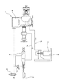
- the grease application apparatus 1a of this example includes, for example, a worm wheel tooth (uneven portion) 11 formed on the peripheral surface of a worm wheel 10 constituting a worm wheel 9 with a shaft corresponding to a member to be applied described in the claims. It includes a drive unit 12, a grease pump 13, an air tank 14, a metering valve 15, and a grease application unit 16.
- the drive unit 12 includes a servo motor 17 and a chuck 19 that is coupled and fixed to the tip of the output shaft 18 of the servo motor 17. Such a drive unit 12 can rotationally drive the shaft-equipped worm wheel 9 while gripping the end portion (lower end portion of FIG. 1) of the shaft member 21 of the shaft-equipped worm wheel 9 by the grip portion 20 of the chuck 19. .
- the grease pump 13 supplies grease (not shown) stored in a tank (not shown) to a metering valve 15 described later by a pump (not shown). Specifically, the grease fed from the grease pump 13 is supplied to the metering valve 15 through a path of the grease hose 22a ⁇ the pressure reducing valve 23 ⁇ the grease hose 22b.
- the pressure reducing valve 23 adjusts (depressurizes) the pressure of the grease supplied from the grease pump 13 and sends it out to the grease hose 22b.
- the grease path is indicated by a broken line arrow
- the air path described later is indicated by a solid line arrow.
- the air tank 14 supplies compressed air (compressed air) to the metering valve 15.
- the air compressed in the air tank 14 is supplied to the metering valve 15 through the route of the air hose 24a ⁇ the first electromagnetic valve 25 ⁇ the air hose 24b ⁇ the speed adjustment valve 26 ⁇ the air hose 24c.
- the first solenoid valve 25 can switch ON / OFF of the metering valve 15 by switching itself ON / OFF. Specifically, when the first electromagnetic valve 25 is ON, the piston constituting the metering valve 15 can be advanced. On the other hand, when the first electromagnetic valve 25 is OFF, the piston constituting the metering valve 15 can be moved backward.
- the speed adjusting valve 26 controls the operation speed (piston advance speed, grease feed speed) of the metering valve 15 by controlling the flow rate and flow rate of the air fed into the metering valve 15.
- the metering valve 15 is, for example, fitted in a cylindrical space composed of an air cylinder (not shown), a grease space provided in a state separated from the air cylinder, and the air cylinder and the grease space.
- One with a mounted piston can be used.
- Grease is supplied from the grease pump 13 to the grease space of the metering valve 15.
- air is supplied from the air tank 14 to the air cylinder of the metering valve 15.
- the piston moves forward and feeds grease from the protruding port of the metering valve 15 to the grease hose 22c.
- the metering valve 15 is provided with a movement start detection function for detecting that the piston has started moving forward, and a movement end detection function for detecting that the piston has finished moving forward.
- a movement start detection function for detecting that the piston has started moving forward
- a movement end detection function for detecting that the piston has finished moving forward.
- Each of these functions can be realized by, for example, a sensor (not shown).
- Information detected by the movement start detection function and the movement end detection function can be used to control the first electromagnetic valve 25 and a second electromagnetic valve 29 described later.
- ON / OFF of the air supply to the air cylinder of the metering valve 15 is switched by ON / OFF switching of the first electromagnetic valve 25. Accordingly, the delivery of grease from the metering valve 15 is started as soon as the first electromagnetic valve 25 is switched ON, and is stopped simultaneously when it is switched OFF.
- the speed adjusting valve 26 can control the flow rate of air supplied to the air cylinder, the flow velocity, etc., and adjust the speed at which the piston moves forward (the amount of grease delivered).
- the pressure in the air cylinder is low, even if the first solenoid valve 25 is switched to ON, the piston does not advance until the pressure in the air cylinder becomes sufficiently high. Therefore, when the pressure in the air cylinder is not sufficiently high, there is a time lag between when the first solenoid valve 25 is turned on and when the piston of the metering valve 15 starts moving forward. There is.
- the grease application unit 16 includes an open / close valve 27 and a nozzle 28.
- the on-off valve 27 is switched ON / OFF (released state / closed state) by ON / OFF switching of the second electromagnetic valve 29.
- the opening / closing valve 27 is ON (in a released state and the second electromagnetic valve 29 is ON)
- the grease supplied from the metering valve 15 can be supplied to the nozzle 28.
- the on-off valve 27 is in an OFF state (closed state and the second electromagnetic valve 29 is OFF)
- the supply of grease to the nozzle 28 is stopped.
- the nozzle 28 is a cylindrical member, and the other side (the right side in FIG. 2) toward the tip side toward a part in the circumferential direction (the worm wheel 9 side half in FIG. 2) of the tip part (upper end part in FIG. 2)
- the inclined portion 30 having a flat surface shape is formed.
- the inclined portion 30 includes a distal end side inclined portion 31 formed at the distal end portion and a portion closer to the distal end, and a proximal end inclined portion 32 formed at a proximal end portion than the portion.
- the inclination angle ⁇ 1 of the distal end side inclined portion 31 with respect to the central axis O of the base portion 33 of the nozzle 28 is larger than the inclination angle ⁇ 2 with respect to the central axis O of the proximal end side inclined portion 32 ( ⁇ 1 > ⁇ 2 ). Then, the front end side opening 34 of the nozzle 28 is opened to the front end side inclined portion 31.
- the inclination angle ⁇ 1 of the tip side inclined portion 31 is restricted to 30 °.
- the inclination angle ⁇ 1 can be regulated in the range of 20 ° to 40 °, preferably in the range of 25 ° to 35 °.
- the inclined portion 30 is configured by the distal end side inclined portion 31 and the proximal end inclined portion 32, but may be configured by one inclined surface.
- the grease application operation described below is performed, for example, in a part of a process for automatically assembling a worm type speed reducer.
- the grease for example, a urea grease having a blending degree of about 220 to 280 is used. However, other various greases can also be used.
- the end portion (lower end portion in FIG. 1) of the shaft member 21 of the worm wheel 9 with the shaft is fixed to the grip portion 20 of the chuck 19 that constitutes the drive unit 12 by a conveying device (not shown).
- the servo motor 17 constituting the drive unit 12 is driven to rotate the shaft-equipped worm wheel 9 at a predetermined rotational speed (rotational speed).
- the rotational state (phase, rotational speed, etc.) of the worm wheel 9 with the shaft is configured to be detected from encoder information provided in the servo motor 17.
- the first solenoid valve 25 is switched to ON to switch the metering valve 15 to ON (operating state).
- the second solenoid valve 29 is switched to ON to turn on the open / close valve 27 (release state).
- the timing at which the second electromagnetic valve 29 is turned on is preferably in a state where the pressure inside the grease hose 22c is high. In the case of this example, the second electromagnetic valve 29 is switched to ON at the same time or slightly after switching the first electromagnetic valve 25 to ON.
- the second solenoid valve 29 may be switched to ON after confirming that the advance of the piston constituting the metering valve 15 has started based on the information detected by the movement start detection function described above. it can.
- the second electromagnetic valve 29 is configured to be switched on at the same time as detecting that the piston has started to move forward by the movement start detection function or after a predetermined time delay. it can.
- the second solenoid valve 29 is turned on. (The opening / closing valve 27 is turned on) is accelerated, and the pressure inside the grease hose 22c can be prevented from decreasing.
- the metering valve 15 when the metering valve 15 is switched to ON, air is supplied to the air cylinder constituting the metering valve 15, and the piston constituting the metering valve 15 starts moving forward. Then, the grease fed from the metering valve 15 as the piston moves forward passes through the on-off valve 27 and flows out from the tip side opening 34 of the nozzle 28 as a liquid or gel-like fluid. It is applied to the worm wheel teeth 11. The forward speed of the piston is adjusted to a predetermined speed by adjusting the flow rate, flow velocity, and the like of the air fed from the speed adjustment valve 26 to predetermined values.
- the forward speed of the piston and the worm with shaft are set so that the time (operation time of the metering valve 15) and the time (work rotation time) required for the shaft worm wheel 9 to make one rotation with respect to the nozzle 28 are equal.
- the rotational speed of the wheel 9 is adjusted beforehand. That is, when the worm wheel 9 with the shaft makes one rotation with respect to the nozzle 28, the application of the grease is restricted.
- a controller (not shown) is provided in order to equalize the piston operation time and the workpiece rotation time.
- various methods including not only electrical control but also mechanical synchronization can be adopted.
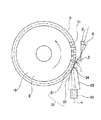
- the tip side inclined portion 31 of the nozzle 28 is arranged so that the tangent line ⁇ of the tip circle ⁇ of the shafted worm wheel 9 is inclined with respect to the central axis O of the base portion 33 of the nozzle 28 of the tip side inclined portion 31. It is installed in a state of being close to and facing the same position as 1 . That is, the nozzle 28 is installed so that the inclination direction of the inclined surface of the tip side inclined portion 31 is parallel to the tangential direction of the tooth tip circle passing through the tooth tip of the worm wheel 9 (tip portion of the convex portion).
- the distance L between the tip side inclined portion 31 and the tip circle of the worm wheel tooth 11 of the worm wheel 9 with the shaft is restricted to 2 mm.
- the distance L can be regulated in the range of 1 mm to 3 mm, preferably in the range of 1.5 mm to 2.5 mm.
- the grease is applied only while the worm wheel 9 with the shaft rotates once with respect to the nozzle 28, and then the first and second electromagnetic valves 25 and 29 are turned off to retract the piston, The drive of the servo motor 17 is stopped and the rotation of the worm wheel 9 with the shaft is decelerated. Then, after confirming that the rotation of the worm wheel 9 with the shaft has stopped based on the encoder information of the servo motor 17, the worm wheel 9 with the shaft is transported to the next process by the transport device.
- the shape of the nozzle 28 is devised and the arrangement mode with respect to the shaft-equipped worm wheel 9 is restricted as described above. Then, while the shaft-equipped worm wheel 9 makes one rotation, liquid grease can be filled by the nozzle 28 so as to be pushed into the recesses (tooth bottom portions) of the worm wheel teeth 11 of the shaft-equipped worm wheel 9. Therefore, a sufficient amount of grease can be applied to the worm wheel teeth 11 of the shaft-equipped worm wheel 9 in a short time. Then, the rotational position of the worm wheel 9 can be detected, and the amount of grease applied to the rotational position can be adjusted in accordance with the detected rotational position of the worm wheel 9.
- the grease application method and the application device of the present invention can apply grease not only to the worm wheel described above but also to various gear members having uneven portions formed on the inner peripheral surface or the outer peripheral surface.
- the on-off valve constituting the above-described grease application device can be omitted.
- the air tank can be omitted.
- the controller restricts the operation time of the metering valve and the work rotation time to be equal.
- a metering valve driven by a screw mechanism such as an electric gear type metering valve (for example, MONO PUMP (registered trademark)) may be employed.
- MONO PUMP registered trademark
- the member to be coated is rotated at a constant speed, and the flow rate of the grease flowing out from the nozzle to the member to be coated is constant.
- the opening of the nozzle faces the concave portion (worm wheel tooth bottom surface) of the uneven portion (worm wheel tooth) of the member to be coated (worm wheel).
- the workpiece rotation speed is regulated to be slow.
Landscapes
- Engineering & Computer Science (AREA)
- General Engineering & Computer Science (AREA)
- Mechanical Engineering (AREA)
- Chemical & Material Sciences (AREA)
- Combustion & Propulsion (AREA)
- Application Of Or Painting With Fluid Materials (AREA)
- Coating Apparatus (AREA)
Abstract
La présente invention concerne un dispositif d'application de graisse qui, pendant qu'une roue à vis sans fin (9) montée sur un arbre est entraînée en rotation au moyen d'une unité d'entraînement (12), fait en sorte qu'une surface inclinée côté pointe d'une buse (28) soit placée pratiquement en face de dents (11) de la roue à vis sans fin (9) montée sur l'arbre. Dans cet état, le dispositif d'application de graisse applique de la graisse liquide sur les dents (11) de la roue à vis sans fin (9) montée sur l'arbre, à partir d'une ouverture côté pointe de la buse (28), de sorte que la graisse pénètre dans les creux des dents (11) de la roue à vis sans fin. Après avoir commencé à appliquer la graisse sur la roue à vis sans fin (9) montée sur l'arbre, le dispositif d'application de graisse termine l'application de la graisse au point où la roue à vis sans fin (9) montée sur l'arbre a effectué une rotation par rapport à la buse (28).
Priority Applications (3)
| Application Number | Priority Date | Filing Date | Title |
|---|---|---|---|
| US15/548,865 US10119608B2 (en) | 2015-03-02 | 2016-02-22 | Grease application method, application device, and methods for manufacturing worm-type reducer, electric power steering device, automobile and variety of industrial machines |
| CN201680012914.7A CN107407459B (zh) | 2015-03-02 | 2016-02-22 | 润滑脂涂布方法和涂布装置 |
| EP16758789.8A EP3267090A4 (fr) | 2015-03-02 | 2016-02-22 | Procédé et dispositif d'application de graisse |
Applications Claiming Priority (2)
| Application Number | Priority Date | Filing Date | Title |
|---|---|---|---|
| JP2015039863A JP6265152B2 (ja) | 2015-03-02 | 2015-03-02 | グリース塗布方法及び塗布装置、並びに、ウォーム減速機の製造方法、電動式パワーステアリング装置の製造方法、自動車の製造方法及び産業機械の製造方法 |
| JP2015-039863 | 2015-03-02 |
Publications (1)
| Publication Number | Publication Date |
|---|---|
| WO2016140095A1 true WO2016140095A1 (fr) | 2016-09-09 |
Family
ID=56846418
Family Applications (1)
| Application Number | Title | Priority Date | Filing Date |
|---|---|---|---|
| PCT/JP2016/055077 WO2016140095A1 (fr) | 2015-03-02 | 2016-02-22 | Procédé et dispositif d'application de graisse |
Country Status (5)
| Country | Link |
|---|---|
| US (1) | US10119608B2 (fr) |
| EP (1) | EP3267090A4 (fr) |
| JP (1) | JP6265152B2 (fr) |
| CN (1) | CN107407459B (fr) |
| WO (1) | WO2016140095A1 (fr) |
Families Citing this family (7)
| Publication number | Priority date | Publication date | Assignee | Title |
|---|---|---|---|---|
| JP6187496B2 (ja) * | 2015-02-16 | 2017-08-30 | 日本精工株式会社 | グリース塗布用ノズル |
| CN107744905A (zh) * | 2017-11-20 | 2018-03-02 | 杭州冠南耐磨材料有限公司 | 一种自动喷漆系统 |
| CN107952601A (zh) * | 2017-12-19 | 2018-04-24 | 新乡市恒星科技有限责任公司 | 一种润滑脂涂布用喷嘴 |
| CN108506466A (zh) * | 2018-04-03 | 2018-09-07 | 青岛宏达锻压机械有限公司 | 电动螺旋压力机齿轮副自动润滑系统 |
| DE102019106692B4 (de) * | 2019-03-15 | 2023-04-13 | Perma-Tec Gmbh & Co. Kg | Schmierstoffspender |
| JP7358124B2 (ja) * | 2019-09-06 | 2023-10-10 | 川崎重工業株式会社 | 基板搬送装置の給脂装置 |
| CN114719169B (zh) * | 2022-03-22 | 2023-12-08 | 陕西法士特齿轮有限责任公司 | 一种变速箱副箱主轴齿轮压板自动喷涂二硫化钼润滑脂机构 |
Citations (5)
| Publication number | Priority date | Publication date | Assignee | Title |
|---|---|---|---|---|
| JPS60104276U (ja) * | 1983-12-20 | 1985-07-16 | トキコ株式会社 | 塗布ノズル |
| JP2010269892A (ja) * | 2009-05-21 | 2010-12-02 | Sanden Corp | チェーン潤滑装置 |
| JP2012172798A (ja) * | 2011-02-23 | 2012-09-10 | Aisin Aw Co Ltd | 自動変速装置の摩擦板潤滑装置 |
| WO2012144035A1 (fr) * | 2011-04-20 | 2012-10-26 | トヨタ自動車株式会社 | Dispositif d'alimentation en huile lubrifiante pour dispositif de transmission d'énergie |
| JP2012237352A (ja) * | 2011-05-11 | 2012-12-06 | Toyota Motor Corp | 潤滑油供給装置 |
Family Cites Families (25)
| Publication number | Priority date | Publication date | Assignee | Title |
|---|---|---|---|---|
| US2017871A (en) * | 1932-04-01 | 1935-10-22 | Hoe & Co R | Lubricant spreader for gears |
| US2220301A (en) * | 1939-05-04 | 1940-11-05 | Ingersoll Rand Co | Oiling device |
| US2235258A (en) * | 1940-06-25 | 1941-03-18 | Fog Nozzle Co | Fire extinguishing nozzle |
| US4815637A (en) * | 1988-04-21 | 1989-03-28 | Nellis Russell L | Cap assembly for use with canned aerosol lubricant |
| US4901679A (en) * | 1988-09-30 | 1990-02-20 | Stanadyne Automotive Corp. | Spray nozzle assembly for piston cooling |
| DE4436505A1 (de) * | 1994-10-13 | 1996-04-18 | Zahnradfabrik Friedrichshafen | Automatgetriebe, insbesondere für Kraftfahrzeuge |
| SE513665C2 (sv) * | 1995-09-25 | 2000-10-16 | Aplicator System Ab | Munstycke för utmatning av härdplast och härdare |
| US5890661A (en) * | 1996-11-27 | 1999-04-06 | Par-Way Group | Colliding stream spray dispensing system with a moldable nozzle |
| TW344682B (en) * | 1996-11-29 | 1998-11-11 | Fuji Transaction Co Ltd | Liquid coating device a liquid coating device comprises a spray supply nozzle, a gas supply passage, and a spray transport passage. |
| DE04014613T1 (de) * | 1998-05-25 | 2005-05-04 | Fuji Bc Engineering Co | Vorrichtung zur Zerstäubung von Flüssigkeiten und Verfahren zum Schneiden |
| US6921680B2 (en) * | 2001-12-31 | 2005-07-26 | Texas Instruments Incorporated | Method and apparatus for MEMS device nebulizer lubrication system |
| KR20040101268A (ko) * | 2002-03-05 | 2004-12-02 | 엔티엔 가부시키가이샤 | 롤링 베어링의 윤활 방법 및 윤활 장치 |
| ITMI20030676A1 (it) * | 2003-04-07 | 2004-10-08 | Auges S R L | Dispositivo e metodo per erogare un fluido lubrificante e/o refrigerante in lavorazioni meccaniche |
| DE10321535B3 (de) * | 2003-05-14 | 2004-10-28 | Repower Systems Ag | Vorrichtung zur Verstellung des Anstellwinkels eines Rotorblatts einer Windkraftanlage |
| KR100692125B1 (ko) * | 2003-10-30 | 2007-03-12 | 현대자동차주식회사 | 무단 변속기의 벨트 윤활 제어장치 |
| US7122220B1 (en) * | 2003-11-12 | 2006-10-17 | Bridgestone Firestone North American Tire, Llc | Method and apparatus for protecting innerliner of a green tire |
| US7699932B2 (en) * | 2004-06-02 | 2010-04-20 | Micron Technology, Inc. | Reactors, systems and methods for depositing thin films onto microfeature workpieces |
| ATE521414T1 (de) * | 2005-05-20 | 2011-09-15 | Emitec Denmark As | Zerstäubung von fluiden durch gegenseitiges zusammenstossen von fluidströmen |
| JP4424293B2 (ja) * | 2005-09-29 | 2010-03-03 | 株式会社ジェイテクト | 転がり軸受装置 |
| US7219849B1 (en) * | 2005-12-13 | 2007-05-22 | Graves Spray Supply, Inc. | Liquid impingement nozzle with paired openings |
| DE102006013865B4 (de) * | 2006-03-23 | 2007-11-22 | Zs Schmieranlagen Vertriebs-Gmbh & Co. Kg | Zahnradabschmiermodul zur automatischen Schmierung von Zahnrädern, insbesondere von Windkraftanlagen |
| US20080149424A1 (en) * | 2006-12-24 | 2008-06-26 | Jen-Sheng Chen | Adjusting structure for an oil feeding device of a linear guideway |
| US8074543B2 (en) * | 2007-03-01 | 2011-12-13 | Mori Seiki Usa, Inc. | Machine tool with cooling nozzle and method for applying cooling fluid |
| JP2012217952A (ja) * | 2011-04-11 | 2012-11-12 | Mitsuba Corp | 噴霧式塗布装置 |
| JP2013210002A (ja) * | 2012-03-30 | 2013-10-10 | Nsk Ltd | 潤滑剤供給機構付き転がり軸受装置 |
-
2015
- 2015-03-02 JP JP2015039863A patent/JP6265152B2/ja active Active
-
2016
- 2016-02-22 CN CN201680012914.7A patent/CN107407459B/zh active Active
- 2016-02-22 WO PCT/JP2016/055077 patent/WO2016140095A1/fr active Application Filing
- 2016-02-22 EP EP16758789.8A patent/EP3267090A4/fr not_active Withdrawn
- 2016-02-22 US US15/548,865 patent/US10119608B2/en active Active
Patent Citations (5)
| Publication number | Priority date | Publication date | Assignee | Title |
|---|---|---|---|---|
| JPS60104276U (ja) * | 1983-12-20 | 1985-07-16 | トキコ株式会社 | 塗布ノズル |
| JP2010269892A (ja) * | 2009-05-21 | 2010-12-02 | Sanden Corp | チェーン潤滑装置 |
| JP2012172798A (ja) * | 2011-02-23 | 2012-09-10 | Aisin Aw Co Ltd | 自動変速装置の摩擦板潤滑装置 |
| WO2012144035A1 (fr) * | 2011-04-20 | 2012-10-26 | トヨタ自動車株式会社 | Dispositif d'alimentation en huile lubrifiante pour dispositif de transmission d'énergie |
| JP2012237352A (ja) * | 2011-05-11 | 2012-12-06 | Toyota Motor Corp | 潤滑油供給装置 |
Non-Patent Citations (1)
| Title |
|---|
| See also references of EP3267090A4 * |
Also Published As
| Publication number | Publication date |
|---|---|
| EP3267090A1 (fr) | 2018-01-10 |
| US20180045296A1 (en) | 2018-02-15 |
| CN107407459A (zh) | 2017-11-28 |
| CN107407459B (zh) | 2019-12-10 |
| EP3267090A4 (fr) | 2018-04-18 |
| JP2016161033A (ja) | 2016-09-05 |
| US10119608B2 (en) | 2018-11-06 |
| JP6265152B2 (ja) | 2018-01-24 |
Similar Documents
| Publication | Publication Date | Title |
|---|---|---|
| WO2016140095A1 (fr) | Procédé et dispositif d'application de graisse | |
| EP3323516B1 (fr) | Procédé de revêtement et dispositif de revêtement | |
| JP6304617B2 (ja) | 流体塗布システムおよび流体塗布方法 | |
| EP4219024A3 (fr) | Système de distribution de colle | |
| JP2016161033A5 (fr) | ||
| US10543505B2 (en) | Nozzle for grease application and methods for using | |
| JP4779422B2 (ja) | 塗装装置 | |
| CN108472679B (zh) | 用于施涂施涂材料的施涂器 | |
| JP2015139725A (ja) | 流体塗布システムおよび流体塗布方法 | |
| US6790284B2 (en) | Coated film forming method and apparatus therefor | |
| CN109475896A (zh) | 用于施加浓稠物质的施涂器、用于此的可更换部件及对应的操作方法 | |
| KR101932083B1 (ko) | 클래딩 장치 | |
| RU2338603C1 (ru) | Устройство для нанесения покрытий на внутреннюю поверхность цилиндрических изделий | |
| JP2015199035A (ja) | 塗布装置 | |
| KR20190080509A (ko) | 전동식 스월 실러 도포 장치 및 이를 이용하는 실러 도포 방법 | |
| KR100671088B1 (ko) | 실러 도포용 스월건 장치 | |
| JP6642407B2 (ja) | 回転霧化塗装装置及び車体塗装方法 | |
| JP2007144249A (ja) | 材料塗布装置 | |
| CN205462974U (zh) | 自动化高粘度胶水涂胶设备及其进胶装置 | |
| JP2006026526A (ja) | 自動スプレーガン | |
| SE2151342A1 (en) | Valve control device with perpendicular axes | |
| JP4728005B2 (ja) | 塗布液供給方法 | |
| JP2020171873A (ja) | 調圧ユニット | |
| JP2001087699A (ja) | 塗装装置用塗料供給システム | |
| JP2018099640A (ja) | 回転霧化塗装装置及び車体塗装方法 |
Legal Events
| Date | Code | Title | Description |
|---|---|---|---|
| 121 | Ep: the epo has been informed by wipo that ep was designated in this application |
Ref document number: 16758789 Country of ref document: EP Kind code of ref document: A1 |
|
| WWE | Wipo information: entry into national phase |
Ref document number: 15548865 Country of ref document: US |
|
| REEP | Request for entry into the european phase |
Ref document number: 2016758789 Country of ref document: EP |
|
| NENP | Non-entry into the national phase |
Ref country code: DE |