WO2016139931A1 - シーム部が識別可能な電縫鋼管及びその製造方法 - Google Patents
シーム部が識別可能な電縫鋼管及びその製造方法 Download PDFInfo
- Publication number
- WO2016139931A1 WO2016139931A1 PCT/JP2016/001098 JP2016001098W WO2016139931A1 WO 2016139931 A1 WO2016139931 A1 WO 2016139931A1 JP 2016001098 W JP2016001098 W JP 2016001098W WO 2016139931 A1 WO2016139931 A1 WO 2016139931A1
- Authority
- WO
- WIPO (PCT)
- Prior art keywords
- steel pipe
- seam
- bead
- color difference
- electric resistance
- Prior art date
- Legal status (The legal status is an assumption and is not a legal conclusion. Google has not performed a legal analysis and makes no representation as to the accuracy of the status listed.)
- Ceased
Links
Images

Classifications
-
- B—PERFORMING OPERATIONS; TRANSPORTING
- B23—MACHINE TOOLS; METAL-WORKING NOT OTHERWISE PROVIDED FOR
- B23K—SOLDERING OR UNSOLDERING; WELDING; CLADDING OR PLATING BY SOLDERING OR WELDING; CUTTING BY APPLYING HEAT LOCALLY, e.g. FLAME CUTTING; WORKING BY LASER BEAM
- B23K11/00—Resistance welding; Severing by resistance heating
- B23K11/36—Auxiliary equipment
-
- B—PERFORMING OPERATIONS; TRANSPORTING
- B21—MECHANICAL METAL-WORKING WITHOUT ESSENTIALLY REMOVING MATERIAL; PUNCHING METAL
- B21C—MANUFACTURE OF METAL SHEETS, WIRE, RODS, TUBES, PROFILES OR LIKE SEMI-MANUFACTURED PRODUCTS OTHERWISE THAN BY ROLLING; AUXILIARY OPERATIONS USED IN CONNECTION WITH METAL-WORKING WITHOUT ESSENTIALLY REMOVING MATERIAL
- B21C37/00—Manufacture of metal sheets, rods, wire, tubes, profiles or like semi-manufactured products, not otherwise provided for; Manufacture of tubes of special shape
- B21C37/06—Manufacture of metal sheets, rods, wire, tubes, profiles or like semi-manufactured products, not otherwise provided for; Manufacture of tubes of special shape of tubes or metal hoses; Combined procedures for making tubes, e.g. for making multi-wall tubes
- B21C37/08—Making tubes with welded or soldered seams
-
- B—PERFORMING OPERATIONS; TRANSPORTING
- B21—MECHANICAL METAL-WORKING WITHOUT ESSENTIALLY REMOVING MATERIAL; PUNCHING METAL
- B21C—MANUFACTURE OF METAL SHEETS, WIRE, RODS, TUBES, PROFILES OR LIKE SEMI-MANUFACTURED PRODUCTS OTHERWISE THAN BY ROLLING; AUXILIARY OPERATIONS USED IN CONNECTION WITH METAL-WORKING WITHOUT ESSENTIALLY REMOVING MATERIAL
- B21C1/00—Manufacture of metal sheets, wire, rods, tubes or like semi-manufactured products by drawing
- B21C1/16—Metal drawing by machines or apparatus in which the drawing action is effected by means other than drums, e.g. by a longitudinally-moved carriage pulling or pushing the work or stock for making metal sheets, rods or tubes
- B21C1/22—Metal drawing by machines or apparatus in which the drawing action is effected by means other than drums, e.g. by a longitudinally-moved carriage pulling or pushing the work or stock for making metal sheets, rods or tubes specially adapted for making tubular articles
- B21C1/24—Metal drawing by machines or apparatus in which the drawing action is effected by means other than drums, e.g. by a longitudinally-moved carriage pulling or pushing the work or stock for making metal sheets, rods or tubes specially adapted for making tubular articles by means of mandrels
-
- B—PERFORMING OPERATIONS; TRANSPORTING
- B21—MECHANICAL METAL-WORKING WITHOUT ESSENTIALLY REMOVING MATERIAL; PUNCHING METAL
- B21C—MANUFACTURE OF METAL SHEETS, WIRE, RODS, TUBES, PROFILES OR LIKE SEMI-MANUFACTURED PRODUCTS OTHERWISE THAN BY ROLLING; AUXILIARY OPERATIONS USED IN CONNECTION WITH METAL-WORKING WITHOUT ESSENTIALLY REMOVING MATERIAL
- B21C37/00—Manufacture of metal sheets, rods, wire, tubes, profiles or like semi-manufactured products, not otherwise provided for; Manufacture of tubes of special shape
- B21C37/06—Manufacture of metal sheets, rods, wire, tubes, profiles or like semi-manufactured products, not otherwise provided for; Manufacture of tubes of special shape of tubes or metal hoses; Combined procedures for making tubes, e.g. for making multi-wall tubes
- B21C37/30—Finishing tubes, e.g. sizing, burnishing
-
- B—PERFORMING OPERATIONS; TRANSPORTING
- B23—MACHINE TOOLS; METAL-WORKING NOT OTHERWISE PROVIDED FOR
- B23K—SOLDERING OR UNSOLDERING; WELDING; CLADDING OR PLATING BY SOLDERING OR WELDING; CUTTING BY APPLYING HEAT LOCALLY, e.g. FLAME CUTTING; WORKING BY LASER BEAM
- B23K11/00—Resistance welding; Severing by resistance heating
- B23K11/08—Seam welding not restricted to one of the preceding subgroups
- B23K11/087—Seam welding not restricted to one of the preceding subgroups for rectilinear seams
- B23K11/0873—Seam welding not restricted to one of the preceding subgroups for rectilinear seams of the longitudinal seam of tubes
-
- B—PERFORMING OPERATIONS; TRANSPORTING
- B23—MACHINE TOOLS; METAL-WORKING NOT OTHERWISE PROVIDED FOR
- B23K—SOLDERING OR UNSOLDERING; WELDING; CLADDING OR PLATING BY SOLDERING OR WELDING; CUTTING BY APPLYING HEAT LOCALLY, e.g. FLAME CUTTING; WORKING BY LASER BEAM
- B23K31/00—Processes relevant to this subclass, specially adapted for particular articles or purposes, but not covered by any single one of main groups B23K1/00 - B23K28/00
- B23K31/10—Processes relevant to this subclass, specially adapted for particular articles or purposes, but not covered by any single one of main groups B23K1/00 - B23K28/00 relating to cutting or desurfacing
-
- F—MECHANICAL ENGINEERING; LIGHTING; HEATING; WEAPONS; BLASTING
- F16—ENGINEERING ELEMENTS AND UNITS; GENERAL MEASURES FOR PRODUCING AND MAINTAINING EFFECTIVE FUNCTIONING OF MACHINES OR INSTALLATIONS; THERMAL INSULATION IN GENERAL
- F16L—PIPES; JOINTS OR FITTINGS FOR PIPES; SUPPORTS FOR PIPES, CABLES OR PROTECTIVE TUBING; MEANS FOR THERMAL INSULATION IN GENERAL
- F16L9/00—Rigid pipes
- F16L9/16—Rigid pipes wound from sheets or strips, with or without reinforcement
- F16L9/165—Rigid pipes wound from sheets or strips, with or without reinforcement of metal
-
- F—MECHANICAL ENGINEERING; LIGHTING; HEATING; WEAPONS; BLASTING
- F16—ENGINEERING ELEMENTS AND UNITS; GENERAL MEASURES FOR PRODUCING AND MAINTAINING EFFECTIVE FUNCTIONING OF MACHINES OR INSTALLATIONS; THERMAL INSULATION IN GENERAL
- F16L—PIPES; JOINTS OR FITTINGS FOR PIPES; SUPPORTS FOR PIPES, CABLES OR PROTECTIVE TUBING; MEANS FOR THERMAL INSULATION IN GENERAL
- F16L9/00—Rigid pipes
- F16L9/17—Rigid pipes obtained by bending a sheet longitudinally and connecting the edges
-
- C—CHEMISTRY; METALLURGY
- C21—METALLURGY OF IRON
- C21D—MODIFYING THE PHYSICAL STRUCTURE OF FERROUS METALS; GENERAL DEVICES FOR HEAT TREATMENT OF FERROUS OR NON-FERROUS METALS OR ALLOYS; MAKING METAL MALLEABLE, e.g. BY DECARBURISATION OR TEMPERING
- C21D9/00—Heat treatment, e.g. annealing, hardening, quenching or tempering, adapted for particular articles; Furnaces therefor
- C21D9/08—Heat treatment, e.g. annealing, hardening, quenching or tempering, adapted for particular articles; Furnaces therefor for tubular bodies or pipes
-
- C—CHEMISTRY; METALLURGY
- C23—COATING METALLIC MATERIAL; COATING MATERIAL WITH METALLIC MATERIAL; CHEMICAL SURFACE TREATMENT; DIFFUSION TREATMENT OF METALLIC MATERIAL; COATING BY VACUUM EVAPORATION, BY SPUTTERING, BY ION IMPLANTATION OR BY CHEMICAL VAPOUR DEPOSITION, IN GENERAL; INHIBITING CORROSION OF METALLIC MATERIAL OR INCRUSTATION IN GENERAL
- C23C—COATING METALLIC MATERIAL; COATING MATERIAL WITH METALLIC MATERIAL; SURFACE TREATMENT OF METALLIC MATERIAL BY DIFFUSION INTO THE SURFACE, BY CHEMICAL CONVERSION OR SUBSTITUTION; COATING BY VACUUM EVAPORATION, BY SPUTTERING, BY ION IMPLANTATION OR BY CHEMICAL VAPOUR DEPOSITION, IN GENERAL
- C23C22/00—Chemical surface treatment of metallic material by reaction of the surface with a reactive liquid, leaving reaction products of surface material in the coating, e.g. conversion coatings, passivation of metals
- C23C22/05—Chemical surface treatment of metallic material by reaction of the surface with a reactive liquid, leaving reaction products of surface material in the coating, e.g. conversion coatings, passivation of metals using aqueous solutions
- C23C22/06—Chemical surface treatment of metallic material by reaction of the surface with a reactive liquid, leaving reaction products of surface material in the coating, e.g. conversion coatings, passivation of metals using aqueous solutions using aqueous acidic solutions with pH less than 6
- C23C22/07—Chemical surface treatment of metallic material by reaction of the surface with a reactive liquid, leaving reaction products of surface material in the coating, e.g. conversion coatings, passivation of metals using aqueous solutions using aqueous acidic solutions with pH less than 6 containing phosphates
- C23C22/08—Orthophosphates
- C23C22/12—Orthophosphates containing zinc cations
Definitions
- the present invention relates to an electric resistance welded steel pipe capable of identifying a seam portion, which can be identified in a final product, and a manufacturing method thereof.
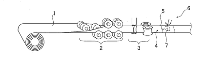
- the pipe making process for producing an electric resistance steel pipe rolls the width of the band steel 1 while continuously feeding the band steel 1. 2, both ends of the rounded width are joined by electro-welding 3 to form a steel pipe 4, and the outer surface bead formed on the pipe outer surface side of the seam portion 5, which is the joined portion, is removed by cutting.
- the outer surface bead cutting 6 is performed.
- inner surface bead cutting 7 is performed to cut and remove the inner surface bead that is formed on the inner surface side of the pipe of the seam portion 5.
- the combined use of the outer bead cutting 6 and the inner bead cutting 7 is called inner / outer bead cutting.
- the ERW steel pipe was adapted to each processing form when it was subjected to secondary processing such as plastic processing such as bending processing and pipe length welding of the plate end and the pipe outer surface of the separately prepared plate material. In many cases, it is necessary to arrange and process the seam portion at the optimum position. It is desired that the steel pipe 4 for such secondary processing applications can identify the seam portion at the processing site.
- the seam is identified visually or magnetically. However, these have the following difficulties.
- the electro-welded welded portion as it is made of pipe is discolored in black compared to other portions due to oxidation, so that the black portion can be identified as a seam portion.
- heat treatment such as tempering is performed after pipe making, the entire surface of the tube body turns black, and the seam portion cannot be identified.
- the seam portion has an outer surface portion that has undergone the outer surface bead cutting, which is recessed as compared with other portions, and since this recess can be recognized even after heat treatment, it can be identified as a seam portion by recognizing the recess after heat treatment. .
- the outer peripheral shape of the tube body is made uniform and the dent cannot be recognized, and the seam portion after the tube drawing cannot be identified.
- the seam portion at the stage of pipe formation has a magnetic characteristic difference due to the difference in metal structure with other portions
- the seam portion can be identified by detecting the magnetic characteristic difference.
- heat treatment such as tempering is performed after pipe making, the difference in the metal structure is eliminated, so that the difference in magnetic characteristics cannot be detected, and the seam portion cannot be identified.
- the unevenness-treated portion remains after the heat treatment and after the tube drawing by the rolling tool, so that it is easy to identify the seam portion at the secondary processing site using this as a mark.
- the eddy current inspection inspection (hereinafter referred to as the nondestructive inspection method generally used in the downstream inspection process) , Abbreviated as ECT).
- ECT eddy current inspection inspection
- the tube body is bent or flattened by pressing the rolling tool against the cutting surface on the tube outer surface side.
- the inner bead cutting may be performed together with the outer bead cutting.
- the cutting tool used for the inner surface bead cutting and the inner surface of the tube excessively interfere with each other, leading to excessive thinning or damage to the cutting tool.
- the present invention has no adverse effect on the electric sewing tube process and no adverse effect on the post-tube forming inspection process. It is an object of the present invention to provide an electric-welded steel pipe capable of identifying a seam portion and a manufacturing method thereof, in which a seam portion can be identified due to a color difference from the remaining portion.
- a part of the outer surface bead is cut and the whole inner surface bead is cut, and the convex height h of the convex part, which is the remaining part to be cut, is set to 0. of the non-bead part thickness t of the steel pipe.
- the seam part is characterized by being 0.7 times or more and 1.7 times or less. Possible manufacturing method of ERW steel pipe.
- the present invention since there is no pressing of the rolling tool, there is no adverse effect on the electric sewing pipe process and no adverse effect on the inspection process after the pipe forming, and bead cutting of the steel pipe after cold drawing.
- the color difference of the film that can be seen from the outer surface side of the tube appears in the portion and the remaining portion, and the seam portion can be easily identified visually.
- FIG. 1 is a schematic diagram of a cross section in the vicinity of a seam portion showing an example of an ERW steel pipe that can identify the seam portion according to the present invention.
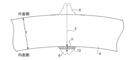
- FIG. 2 is a schematic view of a cross section in the vicinity of the seam portion after inner and outer surface bead cutting showing an example of a method for manufacturing an electric resistance welded steel pipe capable of identifying the seam portion according to the present invention.
- FIG. 3 is a schematic view showing an example of an electric sewing tube process.
- an electric resistance welded steel pipe 100 in which a seam part according to the present invention is identifiable covers a steel pipe part 10 having a seam part 5 formed by electric resistance welding and at least the outer surface side of the steel pipe part 10.
- the portion within the thickness range is a color difference portion 20 that is a portion where the color difference from the remaining portion (portion other than the pipe circumferential width W) can be visually recognized.
- the color difference portion 20 has a color difference from the remaining portion due to the film portion 11 at the bead cutting site being subjected to a greater reduction during cold drawing. Due to the presence of the color difference portion 20, the ERW steel pipe 100 that can identify the seam portion according to the present invention can easily visually identify the position of the seam portion 5 on the pipe outer surface side.
- a preferable manufacturing method for obtaining the ERW steel pipe 100 is as follows. That is, such a manufacturing method is obtained by rounding the width of the steel strip by roll forming while continuously feeding the steel strip, joining both ends in the width direction of the rounded steel strip by electro-welding, and joining the steel strips. After forming a steel pipe having a seam portion, cutting the inner and outer surfaces of the steel pipe by the bead cutting (the electric sewing pipe step), and then applying a zinc phosphate coating on at least the outer surface of the steel pipe, the steel pipe And a drawing step of performing cold drawing using a plug and a die.
- the zinc phosphate coating is applied as a lubricating coating during cold drawing.
- the preferred manufacturing method for obtaining the electric resistance welded steel pipe 100 further targets the steel pipe 4 (the steel pipe that becomes the steel pipe part 10 after the drawing process), for example, as shown in FIG.
- the outer bead 8 is partly cut and the inner bead 9 is entirely cut, and the convex height h of the convex part, which is the remaining part to be cut, is defined as ⁇ of the non-bead thickness t of the steel pipe. It is good also as more than twice and below beta times.
- the pipe circumferential direction portion where the convex portion 12 is located has a larger thickness reduction rate than the remaining pipe circumferential direction portion. For this reason, a greater reduction is applied to the zinc phosphate coating applied to at least the outer surface of the steel pipe 4 (the coating that becomes the coating portion 11 in FIG. 1 after the drawing step).
- the coating portion 11 a portion that exists directly above the seam portion 5, and the width W in the pipe circumferential direction of the portion is not less than 0.1 times the wall thickness.
- the part which becomes a range becomes the color difference part 20 which is a part which can visually recognize the color difference with the other part (parts other than the pipe circumferential direction width W) by receiving a larger reduction.
- the pipe circumferential direction width W becomes the color difference portion 20.
- the convex height h of the convex portion 12 is set to ⁇ times or more and ⁇ times or less of the non-bead portion thickness t.
- Such control of the convex height h can be performed by adjusting the blade height position of a cutting tool (cutting tool) used for inner surface bead cutting or outer surface bead cutting.
- the thickness of the zinc phosphate coating applied before cold drawing may be in the usual range, for example, 1 to 30 ⁇ m.
- the film is immersed in a zinc phosphate bath.
- a seam annealer (not shown) (only the seam portion 5 is heated by, for example, a high frequency induction heating method).
- the seam portion 5 may be subjected to heat treatment (referred to as “seam annealing”).
- the steel pipe 4 was manufactured by the electric sewing pipe process. In this production, inner and outer surface bead cutting was performed, and at that time, the outer surface bead 8 was all cut and the inner surface bead 9 was partially left. By adjusting the blade height position of the inner surface bead cutting bite, the convex height h of the convex portion 12 which is the uncut portion was varied as shown in Table 1.
- the seam annealing was performed to obtain a steel pipe having the tube size before the drawing process shown in Table 1.
- the wall thickness t in the tube size before the drawing process is the non-bead portion wall thickness t.
- the steel pipe 4 obtained by the electric sewing pipe process was subjected to cold drawing using the plug and the die.
- the coating thickness which is the thickness of the zinc phosphate coating applied to the outer surface of the steel pipe 4, and the pipe size after the drawing process were as shown in Table 1.
- the zinc phosphate coating was formed by immersing a steel pipe before cold drawing in a zinc phosphate bath.
- the film part 11 on the outer surface of the product tube formed by cold drawing was visually observed to determine whether or not the color difference part 20 could identify the seam part.
- the results are shown in Table 1.
- a circle mark in the seam part identification column indicates that identification is possible, and a cross mark indicates that identification is not possible.
- the color difference part 20 was judged visually (it is visually recognizable because it is whiter than the surroundings).
- the pipe circumferential width W was measured with a caliper.
- the seam portion 5 can be identified by appearing in the tube axis direction width W.
- the convex height h of the convex portion 12 is excessively small (h / t is less than ⁇ )
- the color difference portion 20 does not appear, and the convex height h is excessively large (h / t is ⁇
- the plug could not be inserted into the inner surface of the tube and cold drawing could not be performed ("drawing is not possible" in the tube size column after the drawing process). Neither appeared, and none of the seam portions could be identified.
Landscapes
- Engineering & Computer Science (AREA)
- Mechanical Engineering (AREA)
- General Engineering & Computer Science (AREA)
- Chemical & Material Sciences (AREA)
- General Chemical & Material Sciences (AREA)
- Chemical Kinetics & Catalysis (AREA)
- Materials Engineering (AREA)
- Metallurgy (AREA)
- Organic Chemistry (AREA)
- Butt Welding And Welding Of Specific Article (AREA)
Abstract
Description
(1) 電縫溶接してなるシーム部を有する鋼管部と、該鋼管部の少なくとも外面側を覆ったリン酸亜鉛の皮膜部とを有する電縫鋼管であって、前記皮膜部のうち、前記シーム部の直上に存在する部分であって、該部分の管周方向幅Wが肉厚の0.1倍以上肉厚以下の範囲となる部分がそれ以外の部分との色の違いが視認できる部分である色差部となっていることを特徴とするシーム部が識別可能な電縫鋼管。
(2) 前記(1)に記載のシーム部が識別可能な電縫鋼管を製造する方法であって、帯鋼を連続送りしながら、前記帯鋼の幅をロール成形により丸め、該丸めた帯鋼の幅方向両端を電縫溶接により接合し、該接合してなるシーム部を具備した鋼管となし、該鋼管の内外面ビード切削を行い、その後、該鋼管の少なくとも外面にリン酸亜鉛の皮膜を施した後、該鋼管にプラグ及びダイスを用いた冷間引抜を施す工程を有し、前記内外面ビード切削を行う際、外面ビードは全部切削して内面ビードは一部残して切削し、または、外面ビードは一部残して切削して内面ビードは全部切削し、この一部残して切削する残し部分である凸部の凸高さhを前記鋼管の非ビード部肉厚tの0.07倍以上1.7倍以下とすることを特徴とするシーム部が識別可能な電縫鋼管の製造方法。

2 ロール成形
3 電縫溶接
4 鋼管(電縫溶接してなるシーム部を有する鋼管)
5 シーム部
6 外面ビード切削
7 内面ビード切削
8 外面ビード
9 内面ビード
10 鋼管部
11 皮膜部(リン酸亜鉛の皮膜部)
12 凸部(内面ビードの切削残し)
20 色差部
100 シーム部が識別可能な電縫鋼管
Claims (2)
- 電縫溶接してなるシーム部を有する鋼管部と、該鋼管部の少なくとも外面側を覆ったリン酸亜鉛の皮膜部とを有する電縫鋼管であって、前記皮膜部のうち、前記シーム部の直上に存在する部分であって、該部分の管周方向幅Wが肉厚の0.1倍以上肉厚以下の範囲となる部分がそれ以外の部分との色の違いが視認できる部分である色差部となっていることを特徴とするシーム部が識別可能な電縫鋼管。
- 請求項1に記載のシーム部が識別可能な電縫鋼管を製造する方法であって、
帯鋼を連続送りしながら、前記帯鋼の幅をロール成形により丸め、該丸めた帯鋼の幅方向両端を電縫溶接により接合し、該接合してなるシーム部を具備した鋼管となし、該鋼管の内外面ビード切削を行い、その後、該鋼管の少なくとも外面にリン酸亜鉛の皮膜を施した後、該鋼管にプラグ及びダイスを用いた冷間引抜を施す工程を有し、
前記内外面ビード切削を行う際、外面ビードは全部切削して内面ビードは一部残して切削し、または、外面ビードは一部残して切削して内面ビードは全部切削し、この一部残して切削する残し部分である凸部の凸高さhを前記鋼管の非ビード部肉厚tの0.07倍以上1.7倍以下とすることを特徴とするシーム部が識別可能な電縫鋼管の製造方法。
Priority Applications (6)
| Application Number | Priority Date | Filing Date | Title |
|---|---|---|---|
| US15/555,401 US10369655B2 (en) | 2015-03-03 | 2016-03-01 | Electric resistance welded steel pipe having identifiable seam portion and method for manufacturing the same |
| JP2016533677A JP6233516B2 (ja) | 2015-03-03 | 2016-03-01 | シーム部が識別可能な電縫鋼管の製造方法 |
| KR1020177023827A KR101954698B1 (ko) | 2015-03-03 | 2016-03-01 | 시임부가 식별 가능한 전봉 강관 및 그의 제조 방법 |
| MX2017011145A MX2017011145A (es) | 2015-03-03 | 2016-03-01 | Tubo de acero soldado por resistencia electrica que tiene porcion de costura identificable y metodo para la fabricacion del mismo. |
| CN201680013025.2A CN107405659B (zh) | 2015-03-03 | 2016-03-01 | 焊缝部能够识别的电焊钢管的制造方法 |
| US16/403,731 US11045896B2 (en) | 2015-03-03 | 2019-05-06 | Electric resistance welded steel pipe having identifiable seam portion and method for manufacturing the same |
Applications Claiming Priority (2)
| Application Number | Priority Date | Filing Date | Title |
|---|---|---|---|
| JP2015-040928 | 2015-03-03 | ||
| JP2015040928 | 2015-03-03 |
Related Child Applications (2)
| Application Number | Title | Priority Date | Filing Date |
|---|---|---|---|
| US15/555,401 A-371-Of-International US10369655B2 (en) | 2015-03-03 | 2016-03-01 | Electric resistance welded steel pipe having identifiable seam portion and method for manufacturing the same |
| US16/403,731 Division US11045896B2 (en) | 2015-03-03 | 2019-05-06 | Electric resistance welded steel pipe having identifiable seam portion and method for manufacturing the same |
Publications (1)
| Publication Number | Publication Date |
|---|---|
| WO2016139931A1 true WO2016139931A1 (ja) | 2016-09-09 |
Family
ID=56849310
Family Applications (1)
| Application Number | Title | Priority Date | Filing Date |
|---|---|---|---|
| PCT/JP2016/001098 Ceased WO2016139931A1 (ja) | 2015-03-03 | 2016-03-01 | シーム部が識別可能な電縫鋼管及びその製造方法 |
Country Status (6)
| Country | Link |
|---|---|
| US (2) | US10369655B2 (ja) |
| JP (1) | JP6233516B2 (ja) |
| KR (1) | KR101954698B1 (ja) |
| CN (1) | CN107405659B (ja) |
| MX (1) | MX2017011145A (ja) |
| WO (1) | WO2016139931A1 (ja) |
Families Citing this family (1)
| Publication number | Priority date | Publication date | Assignee | Title |
|---|---|---|---|---|
| DE102023124000A1 (de) * | 2023-09-06 | 2025-03-06 | Maschinenfabrik Bernard Krone GmbH & Co. KG | Bindenadel für eine nadelschwinge einer ballenpresse |
Citations (4)
| Publication number | Priority date | Publication date | Assignee | Title |
|---|---|---|---|---|
| JPS54118372A (en) * | 1978-03-07 | 1979-09-13 | Sumitomo Metal Ind Ltd | Production of cold drawn steel pipe from electrically seamed steel pipe |
| JPS6393424A (ja) * | 1986-10-07 | 1988-04-23 | Nisshin Steel Co Ltd | 薄肉電縫管の製造法 |
| JPH04197513A (ja) * | 1990-11-27 | 1992-07-17 | Nippon Steel Corp | コイル状鋼管の芯引方法 |
| JP2015168003A (ja) * | 2014-03-11 | 2015-09-28 | Jfeスチール株式会社 | 電縫鋼管及びその製造方法 |
Family Cites Families (9)
| Publication number | Priority date | Publication date | Assignee | Title |
|---|---|---|---|---|
| US2139771A (en) * | 1932-11-03 | 1938-12-13 | Midland Steel Prod Co | Method and apparatus for welding |
| US3716908A (en) * | 1971-09-27 | 1973-02-20 | Anaconda American Brass Co | Method for welding |
| US5604040A (en) * | 1991-08-09 | 1997-02-18 | Associated Universities, Inc. | Zinc phosphate conversion coatings |
| US7157672B2 (en) * | 2003-05-20 | 2007-01-02 | Gandy Technologies Corporation | Method of manufacturing stainless steel pipe for use in piping systems |
| JP2005125385A (ja) | 2003-10-24 | 2005-05-19 | Toshida Kogyo Kk | 電縫管の内面ビード削除方法及び装置 |
| CN101148012A (zh) | 2007-10-15 | 2008-03-26 | 胜利油田孚瑞特石油装备有限责任公司 | 空心抽油杆的加工方法 |
| US8365602B2 (en) * | 2009-10-09 | 2013-02-05 | Olympus Ndt, Inc. | Weld seam tracking system using phased array ultrasonic devices |
| JP5771821B2 (ja) | 2010-08-17 | 2015-09-02 | 日鉄住金鋼管株式会社 | 電縫鋼管、電縫鋼管の製造方法、管状製品の製造方法 |
| JP5994760B2 (ja) * | 2013-10-08 | 2016-09-21 | Jfeスチール株式会社 | 電縫鋼管の製造方法 |
-
2016
- 2016-03-01 MX MX2017011145A patent/MX2017011145A/es unknown
- 2016-03-01 CN CN201680013025.2A patent/CN107405659B/zh not_active Expired - Fee Related
- 2016-03-01 JP JP2016533677A patent/JP6233516B2/ja active Active
- 2016-03-01 KR KR1020177023827A patent/KR101954698B1/ko not_active Expired - Fee Related
- 2016-03-01 WO PCT/JP2016/001098 patent/WO2016139931A1/ja not_active Ceased
- 2016-03-01 US US15/555,401 patent/US10369655B2/en not_active Expired - Fee Related
-
2019
- 2019-05-06 US US16/403,731 patent/US11045896B2/en not_active Expired - Fee Related
Patent Citations (4)
| Publication number | Priority date | Publication date | Assignee | Title |
|---|---|---|---|---|
| JPS54118372A (en) * | 1978-03-07 | 1979-09-13 | Sumitomo Metal Ind Ltd | Production of cold drawn steel pipe from electrically seamed steel pipe |
| JPS6393424A (ja) * | 1986-10-07 | 1988-04-23 | Nisshin Steel Co Ltd | 薄肉電縫管の製造法 |
| JPH04197513A (ja) * | 1990-11-27 | 1992-07-17 | Nippon Steel Corp | コイル状鋼管の芯引方法 |
| JP2015168003A (ja) * | 2014-03-11 | 2015-09-28 | Jfeスチール株式会社 | 電縫鋼管及びその製造方法 |
Also Published As
| Publication number | Publication date |
|---|---|
| KR20170107075A (ko) | 2017-09-22 |
| US10369655B2 (en) | 2019-08-06 |
| KR101954698B1 (ko) | 2019-03-06 |
| JP6233516B2 (ja) | 2017-11-22 |
| US20190255646A1 (en) | 2019-08-22 |
| US11045896B2 (en) | 2021-06-29 |
| CN107405659B (zh) | 2019-06-07 |
| JPWO2016139931A1 (ja) | 2017-04-27 |
| CN107405659A (zh) | 2017-11-28 |
| US20180036830A1 (en) | 2018-02-08 |
| MX2017011145A (es) | 2017-11-28 |
Similar Documents
| Publication | Publication Date | Title |
|---|---|---|
| CA2640235C (en) | Method of manufacturing lined tubing | |
| JP2014004626A (ja) | 異径管状部品の製造方法および成形金型 | |
| JP6015686B2 (ja) | 電縫鋼管の製造方法 | |
| JP6233516B2 (ja) | シーム部が識別可能な電縫鋼管の製造方法 | |
| US11712727B2 (en) | Bend pipe and method for manufacturing same | |
| JP6083402B2 (ja) | 電縫鋼管の製造方法 | |
| JP5803606B2 (ja) | 電縫管の製造方法及びローレット加工治具 | |
| JP5994760B2 (ja) | 電縫鋼管の製造方法 | |
| JP2004148337A (ja) | 溶接鋼管の接合部成形方法及びその製造装置 | |
| JP2007253331A (ja) | プレス成形用クラッド材及びそのクラッド材によってプレス成形されたシームレス缶 | |
| JPS63224814A (ja) | 車輪のリム用溶接鋼管の製造方法 | |
| JP5884750B2 (ja) | 電縫鋼管の接合部成形方法及びその製造装置 | |
| JP2004114101A (ja) | 電縫鋼管の管内面平滑化方法および装置 | |
| JP4779465B2 (ja) | 鋼管の曲がり防止方法 | |
| JP5055843B2 (ja) | 溶接部特性の良好な電縫管の製造方法 | |
| JP6127709B2 (ja) | プレス切断用電縫管及びその製造方法 | |
| JPH10328729A (ja) | 内面溝付伝熱管の製造方法 | |
| JP2007245218A (ja) | Uプレス装置およびuプレス方法 | |
| JP2010137231A (ja) | 加工性の良好な鍛接管 | |
| JP2011115820A (ja) | フレア加工後の面が良好な鍛接鋼管 | |
| JP2007090416A (ja) | 溶接部特性の良好な電縫管製造方法 | |
| JPS63252628A (ja) | 自動車用車輪のリムの製造方法 | |
| JP2007090414A (ja) | 溶接部特性の良好な電縫管製造方法 | |
| JP2008012581A (ja) | 溶接部特性の良好な電縫管の製造方法 | |
| JP2013154402A (ja) | 加工性の良好な鍛接管 |
Legal Events
| Date | Code | Title | Description |
|---|---|---|---|
| ENP | Entry into the national phase |
Ref document number: 2016533677 Country of ref document: JP Kind code of ref document: A |
|
| 121 | Ep: the epo has been informed by wipo that ep was designated in this application |
Ref document number: 16758629 Country of ref document: EP Kind code of ref document: A1 |
|
| ENP | Entry into the national phase |
Ref document number: 20177023827 Country of ref document: KR Kind code of ref document: A |
|
| WWE | Wipo information: entry into national phase |
Ref document number: MX/A/2017/011145 Country of ref document: MX |
|
| WWE | Wipo information: entry into national phase |
Ref document number: 15555401 Country of ref document: US |
|
| NENP | Non-entry into the national phase |
Ref country code: DE |
|
| 122 | Ep: pct application non-entry in european phase |
Ref document number: 16758629 Country of ref document: EP Kind code of ref document: A1 |