WO2016139856A1 - 圧電アクチュエーター装置及びその制御方法 - Google Patents
圧電アクチュエーター装置及びその制御方法 Download PDFInfo
- Publication number
- WO2016139856A1 WO2016139856A1 PCT/JP2015/083667 JP2015083667W WO2016139856A1 WO 2016139856 A1 WO2016139856 A1 WO 2016139856A1 JP 2015083667 W JP2015083667 W JP 2015083667W WO 2016139856 A1 WO2016139856 A1 WO 2016139856A1
- Authority
- WO
- WIPO (PCT)
- Prior art keywords
- piezoelectric
- resonance
- actuator device
- driving
- piezoelectric element
- Prior art date
- Legal status (The legal status is an assumption and is not a legal conclusion. Google has not performed a legal analysis and makes no representation as to the accuracy of the status listed.)
- Ceased
Links
Images


Classifications
-
- H—ELECTRICITY
- H02—GENERATION; CONVERSION OR DISTRIBUTION OF ELECTRIC POWER
- H02N—ELECTRIC MACHINES NOT OTHERWISE PROVIDED FOR
- H02N2/00—Electric machines in general using piezoelectric effect, electrostriction or magnetostriction
- H02N2/02—Electric machines in general using piezoelectric effect, electrostriction or magnetostriction producing linear motion, e.g. actuators; Linear positioners ; Linear motors
- H02N2/021—Electric machines in general using piezoelectric effect, electrostriction or magnetostriction producing linear motion, e.g. actuators; Linear positioners ; Linear motors using intermittent driving, e.g. step motors, piezoleg motors
- H02N2/025—Inertial sliding motors
-
- G—PHYSICS
- G02—OPTICS
- G02B—OPTICAL ELEMENTS, SYSTEMS OR APPARATUS
- G02B7/00—Mountings, adjusting means, or light-tight connections, for optical elements
- G02B7/02—Mountings, adjusting means, or light-tight connections, for optical elements for lenses
- G02B7/04—Mountings, adjusting means, or light-tight connections, for optical elements for lenses with mechanism for focusing or varying magnification
- G02B7/08—Mountings, adjusting means, or light-tight connections, for optical elements for lenses with mechanism for focusing or varying magnification adapted to co-operate with a remote control mechanism
-
- H—ELECTRICITY
- H02—GENERATION; CONVERSION OR DISTRIBUTION OF ELECTRIC POWER
- H02N—ELECTRIC MACHINES NOT OTHERWISE PROVIDED FOR
- H02N2/00—Electric machines in general using piezoelectric effect, electrostriction or magnetostriction
- H02N2/02—Electric machines in general using piezoelectric effect, electrostriction or magnetostriction producing linear motion, e.g. actuators; Linear positioners ; Linear motors
- H02N2/06—Drive circuits; Control arrangements or methods
- H02N2/065—Large signal circuits, e.g. final stages
- H02N2/067—Large signal circuits, e.g. final stages generating drive pulses
-
- G—PHYSICS
- G03—PHOTOGRAPHY; CINEMATOGRAPHY; ANALOGOUS TECHNIQUES USING WAVES OTHER THAN OPTICAL WAVES; ELECTROGRAPHY; HOLOGRAPHY
- G03B—APPARATUS OR ARRANGEMENTS FOR TAKING PHOTOGRAPHS OR FOR PROJECTING OR VIEWING THEM; APPARATUS OR ARRANGEMENTS EMPLOYING ANALOGOUS TECHNIQUES USING WAVES OTHER THAN OPTICAL WAVES; ACCESSORIES THEREFOR
- G03B2205/00—Adjustment of optical system relative to image or object surface other than for focusing
- G03B2205/0053—Driving means for the movement of one or more optical element
- G03B2205/0061—Driving means for the movement of one or more optical element using piezoelectric actuators
-
- G—PHYSICS
- G03—PHOTOGRAPHY; CINEMATOGRAPHY; ANALOGOUS TECHNIQUES USING WAVES OTHER THAN OPTICAL WAVES; ELECTROGRAPHY; HOLOGRAPHY
- G03B—APPARATUS OR ARRANGEMENTS FOR TAKING PHOTOGRAPHS OR FOR PROJECTING OR VIEWING THEM; APPARATUS OR ARRANGEMENTS EMPLOYING ANALOGOUS TECHNIQUES USING WAVES OTHER THAN OPTICAL WAVES; ACCESSORIES THEREFOR
- G03B3/00—Focusing arrangements of general interest for cameras, projectors or printers
- G03B3/10—Power-operated focusing
Definitions
- the driving member can be displaced with an optimum sawtooth wave using a piezoelectric element, and the driving target coupled with the driving member with a predetermined frictional force can be moved at high speed.
- An excellent piezoelectric actuator device and a control method thereof can be provided.
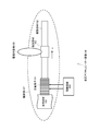
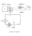
- FIG. 3 shows a mechanical model of the piezoelectric actuator device 100 using the drive circuit 104 shown in FIG.
- m 1 is the mass of the support member 105
- m 2 is the mass of the driving member 102
- m 3 is the mass of the driven object 106
- k is a spring constant of the piezoelectric element 101
- c v is the damping coefficient of the piezoelectric element 101
- F is the force
- N is a pressing force of the engaging member 103
- ⁇ is a coefficient of friction between the driving member 102 and the engaging member 103, and therefore ⁇ N is a frictional force.
- (A1) The difference between the time t f during which the drive member 102 moves fast and the time t s during which the drive member 102 moves slowly is increased as much as possible.
- (A2) The maximum speed (v 102, p ) of the driving member 102 at the time t s is increased as much as possible.
- (A3) At time t s , the time during which the drive member 102 is near the maximum speed (v 102, p ) is made as long as possible.
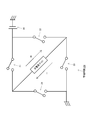
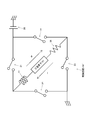
- FIG. 6 shows a drive circuit 104 ′ that inputs a drive voltage to the piezoelectric element 101 according to another configuration example.
- the difference from the drive circuit 104 shown in FIG. 2 is that an inductor 27 and a resistor 28 are connected in series to both ends of the piezoelectric element 101. It is assumed that a drive control circuit (not shown) controls the switching operations of the switches 21 to 24.
- the governing equation of the piezoelectric actuator device 700 becomes the fourth-order differential equation (18) (of the displacement x of the driving member 102) as described above, and two resonance phenomena appear because the inductor 27 and the resistor 28 are connected in series. This is brought about by a new configuration (see FIG. 6 or FIG. 7) in which a driving voltage is applied to the piezoelectric element 101.
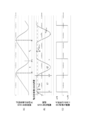
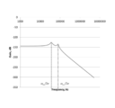
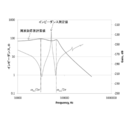
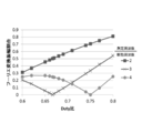
- FIG. 8 shows an example of the frequency response of the transfer function expressed by the above equation (22).
- the first term on the right side represents piezoelectric mechanical resonance
- the second term represents piezoelectric electrical resonance
- the speed of the piezoelectric actuator device 700 (driving member 102) is similarly superposed of two vibrations.
- the angular frequency of this vibration is ⁇ 1 and ⁇ 2 for both position and velocity.
- ⁇ 1 and ⁇ 2 are the following equation (40) from the above equation (25). Therefore, if the damping ratio ⁇ is small, the natural circular frequencies ⁇ n1 and ⁇ n2 are almost equal to each other.
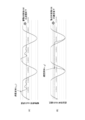
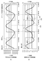
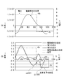
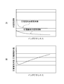
- FIGS. 11A and 11B show waveforms of the position and speed of the drive member 102 in the piezoelectric actuator device 700 when the drive circuit 104 ′ shown in FIG. 6 is used.
- the waveform shown in FIG. 11 is an analytical solution of the response waveform of the piezoelectric actuator device 700 obtained from the above equations (36) and (38).
- the speed of the driving member 120 is the sum of the speeds of the first component and the second component.
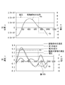
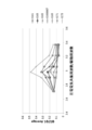
- FIGS. 12A and 12B show the position and velocity waveforms of the drive member 102 in the piezoelectric actuator device 700 when the drive circuit 104 shown in FIG. 2 is used as a comparison with FIG. Show.
- the speed, if the damping ratio zeta 1 of the first component is small, the time t pmin time t pmax and first MIN values of first MAX value of the first component are respectively the following formulas ( 45).
- the piezoelectric actuator device includes, for example, adjustment of a photographing lens position of a camera, adjustment of a projection lens position of an overhead projector, adjustment of a lens position of binoculars (or a telescope or a microscope), and XY movement. It can be used to move the stage.
- the first resonance phenomenon has an electrical influence on the series connection body due to the piezoelectric effect of the piezoelectric element while mainly driving mechanical resonance of the piezoelectric actuator device with respect to driving by the piezoelectric element.
- the second resonance phenomenon is a piezoelectric electrical resonance that is influenced by the mechanical vibration of the driving member due to the piezoelectric effect of the piezoelectric element while mainly conducting electrical resonance.
- the first resonance phenomenon mainly includes a two-mass mechanical resonance frequency defined based on an equivalent spring constant determined from a physical property value of the piezoelectric element and a mass of the driving member.
Landscapes
- Physics & Mathematics (AREA)
- General Physics & Mathematics (AREA)
- Optics & Photonics (AREA)
- General Electrical Machinery Utilizing Piezoelectricity, Electrostriction Or Magnetostriction (AREA)
- Lens Barrels (AREA)
Priority Applications (1)
| Application Number | Priority Date | Filing Date | Title |
|---|---|---|---|
| US15/545,118 US20180006584A1 (en) | 2015-03-02 | 2015-11-30 | Piezoelectric actuator apparatus and control method therefor |
Applications Claiming Priority (2)
| Application Number | Priority Date | Filing Date | Title |
|---|---|---|---|
| JP2015-040732 | 2015-03-02 | ||
| JP2015040732A JP2016163437A (ja) | 2015-03-02 | 2015-03-02 | 圧電アクチュエーター装置及びその制御方法 |
Publications (1)
| Publication Number | Publication Date |
|---|---|
| WO2016139856A1 true WO2016139856A1 (ja) | 2016-09-09 |
Family
ID=56847429
Family Applications (1)
| Application Number | Title | Priority Date | Filing Date |
|---|---|---|---|
| PCT/JP2015/083667 Ceased WO2016139856A1 (ja) | 2015-03-02 | 2015-11-30 | 圧電アクチュエーター装置及びその制御方法 |
Country Status (3)
| Country | Link |
|---|---|
| US (1) | US20180006584A1 (enExample) |
| JP (1) | JP2016163437A (enExample) |
| WO (1) | WO2016139856A1 (enExample) |
Cited By (1)
| Publication number | Priority date | Publication date | Assignee | Title |
|---|---|---|---|---|
| CN109831116A (zh) * | 2019-03-26 | 2019-05-31 | 合肥工业大学 | 一种由合成方波驱动的直线压电马达 |
Families Citing this family (3)
| Publication number | Priority date | Publication date | Assignee | Title |
|---|---|---|---|---|
| JP6143321B1 (ja) * | 2017-01-26 | 2017-06-07 | オーツェイド株式会社 | イヤホン及びヘッドホン |
| WO2021044198A1 (en) * | 2019-09-06 | 2021-03-11 | Arcelormittal | Front structure for an electric vehicle |
| CN120825081B (zh) * | 2025-09-15 | 2025-12-05 | 中国科学院长春光学精密机械与物理研究所 | 基于延迟准锯齿波信号的压电陶瓷驱动方法 |
Citations (2)
| Publication number | Priority date | Publication date | Assignee | Title |
|---|---|---|---|---|
| JP2001268951A (ja) * | 2000-03-23 | 2001-09-28 | Minolta Co Ltd | 駆動装置 |
| JP2006522579A (ja) * | 2003-04-02 | 2006-09-28 | ピエゾモーター ウプサラ エイビー | 近共振広範囲動作電気機械式モータ |
Family Cites Families (8)
| Publication number | Priority date | Publication date | Assignee | Title |
|---|---|---|---|---|
| JPH11146655A (ja) * | 1997-11-05 | 1999-05-28 | Taiyo Yuden Co Ltd | 圧電トランス駆動方法及びその装置 |
| IT1318880B1 (it) * | 2000-09-19 | 2003-09-10 | St Microelectronics Srl | Circuito elettronico per il pilotaggio ad alta efficienza di carichipiezo-elettrici con cablaggio induttivo-resisitivo. |
| TW523582B (en) * | 2000-11-24 | 2003-03-11 | Shr-Guang Li | Fourth-order partial differential equation piezoelectric transducer with mutually independent gain and phase functions |
| JP3595808B2 (ja) * | 2002-07-11 | 2004-12-02 | コニカミノルタホールディングス株式会社 | 電圧発生回路及び該回路を備えた駆動装置 |
| JP2012005957A (ja) * | 2010-06-24 | 2012-01-12 | Maxell Finetech Ltd | 駆動装置、画像取得装置、及び電子機器 |
| JP4744636B1 (ja) * | 2010-02-12 | 2011-08-10 | マクセルファインテック株式会社 | 駆動装置、画像取得装置および電子機器 |
| JP6579778B2 (ja) * | 2014-05-14 | 2019-09-25 | キヤノン株式会社 | 振動型駆動装置、振動型駆動装置を備える交換用レンズ、撮像装置、及び振動型駆動装置の製造方法 |
| CN204465480U (zh) * | 2015-03-31 | 2015-07-08 | 合肥航太电物理技术有限公司 | 一种雷电流c分量专控电路 |
-
2015
- 2015-03-02 JP JP2015040732A patent/JP2016163437A/ja active Pending
- 2015-11-30 WO PCT/JP2015/083667 patent/WO2016139856A1/ja not_active Ceased
- 2015-11-30 US US15/545,118 patent/US20180006584A1/en not_active Abandoned
Patent Citations (2)
| Publication number | Priority date | Publication date | Assignee | Title |
|---|---|---|---|---|
| JP2001268951A (ja) * | 2000-03-23 | 2001-09-28 | Minolta Co Ltd | 駆動装置 |
| JP2006522579A (ja) * | 2003-04-02 | 2006-09-28 | ピエゾモーター ウプサラ エイビー | 近共振広範囲動作電気機械式モータ |
Cited By (2)
| Publication number | Priority date | Publication date | Assignee | Title |
|---|---|---|---|---|
| CN109831116A (zh) * | 2019-03-26 | 2019-05-31 | 合肥工业大学 | 一种由合成方波驱动的直线压电马达 |
| CN109831116B (zh) * | 2019-03-26 | 2020-01-03 | 合肥工业大学 | 一种由合成方波驱动的直线压电马达 |
Also Published As
| Publication number | Publication date |
|---|---|
| JP2016163437A (ja) | 2016-09-05 |
| US20180006584A1 (en) | 2018-01-04 |
Similar Documents
| Publication | Publication Date | Title |
|---|---|---|
| JP6579778B2 (ja) | 振動型駆動装置、振動型駆動装置を備える交換用レンズ、撮像装置、及び振動型駆動装置の製造方法 | |
| US8773004B2 (en) | Circuit for optimizing the recovery of vibratory energy by a mechanical/electrical converter | |
| JP5436164B2 (ja) | 振動型アクチュエータの駆動回路 | |
| Hollkamp | Multimodal passive vibration suppression with piezoelectric materials and resonant shunts | |
| WO2016139856A1 (ja) | 圧電アクチュエーター装置及びその制御方法 | |
| CN100566119C (zh) | 运行在共振附近宽范围的机电马达 | |
| JP5037767B2 (ja) | 振動型アクチュエータの制御装置 | |
| US7528527B2 (en) | Driving device | |
| JP2005318720A (ja) | 駆動装置 | |
| CN102468803A (zh) | 音圈电机的控制方法及镜头对焦系统 | |
| JP2012055111A (ja) | 振動型駆動装置の制御装置および振動型駆動装置の出力特性検出方法 | |
| JP2016163437A5 (enExample) | ||
| JP2009284635A (ja) | 駆動装置 | |
| US20240030834A1 (en) | Efficient drive for piezoelectric inertia motors | |
| JP2019134633A (ja) | 振動型駆動装置、振動型アクチュエータの駆動方法及び電子機器 | |
| JP5693699B2 (ja) | 振動体の駆動回路 | |
| Toh et al. | Electronic resonant frequency tuning of a marine energy harvester | |
| KR102019372B1 (ko) | 에너지 하베스팅이 가능한 가변 감쇠력 댐퍼 및 이를 포함한 진동 제어 시스템 | |
| JPH1189253A (ja) | 駆動パルス発生装置 | |
| JP7379285B2 (ja) | 振動型駆動装置、機器、振動型アクチュエータの制御装置 | |
| JP7328056B2 (ja) | 振動型駆動装置、振動型アクチュエータ、および電子機器 | |
| JP2010273439A (ja) | 振動型駆動装置 | |
| WO2021039358A1 (ja) | 駆動装置、駆動方法、および電子機器 | |
| JP2002233173A (ja) | 駆動装置 | |
| Torres-Perez et al. | Energy efficient active vibration control strategies using electromagnetic linear actuators |
Legal Events
| Date | Code | Title | Description |
|---|---|---|---|
| 121 | Ep: the epo has been informed by wipo that ep was designated in this application |
Ref document number: 15884022 Country of ref document: EP Kind code of ref document: A1 |
|
| WWE | Wipo information: entry into national phase |
Ref document number: 15545118 Country of ref document: US |
|
| NENP | Non-entry into the national phase |
Ref country code: DE |
|
| 122 | Ep: pct application non-entry in european phase |
Ref document number: 15884022 Country of ref document: EP Kind code of ref document: A1 |