WO2016137057A1 - 전해 커패시터용 알루미늄 박의 제조 방법, 고유전 상수를 갖는 알루미늄 박, 이를 포함하는 전해 커패시터 및 알루미늄 박의 제조 장치 - Google Patents
전해 커패시터용 알루미늄 박의 제조 방법, 고유전 상수를 갖는 알루미늄 박, 이를 포함하는 전해 커패시터 및 알루미늄 박의 제조 장치 Download PDFInfo
- Publication number
- WO2016137057A1 WO2016137057A1 PCT/KR2015/005087 KR2015005087W WO2016137057A1 WO 2016137057 A1 WO2016137057 A1 WO 2016137057A1 KR 2015005087 W KR2015005087 W KR 2015005087W WO 2016137057 A1 WO2016137057 A1 WO 2016137057A1
- Authority
- WO
- WIPO (PCT)
- Prior art keywords
- aluminum foil
- metal oxide
- chamber
- oxide sol
- pores
- Prior art date
- Legal status (The legal status is an assumption and is not a legal conclusion. Google has not performed a legal analysis and makes no representation as to the accuracy of the status listed.)
- Ceased
Links
Images



Classifications
-
- H—ELECTRICITY
- H01—ELECTRIC ELEMENTS
- H01G—CAPACITORS; CAPACITORS, RECTIFIERS, DETECTORS, SWITCHING DEVICES, LIGHT-SENSITIVE OR TEMPERATURE-SENSITIVE DEVICES OF THE ELECTROLYTIC TYPE
- H01G9/00—Electrolytic capacitors, rectifiers, detectors, switching devices, light-sensitive or temperature-sensitive devices; Processes of their manufacture
- H01G9/004—Details
- H01G9/04—Electrodes or formation of dielectric layers thereon
- H01G9/042—Electrodes or formation of dielectric layers thereon characterised by the material
- H01G9/045—Electrodes or formation of dielectric layers thereon characterised by the material based on aluminium
-
- C—CHEMISTRY; METALLURGY
- C25—ELECTROLYTIC OR ELECTROPHORETIC PROCESSES; APPARATUS THEREFOR
- C25D—PROCESSES FOR THE ELECTROLYTIC OR ELECTROPHORETIC PRODUCTION OF COATINGS; ELECTROFORMING; APPARATUS THEREFOR
- C25D11/00—Electrolytic coating by surface reaction, i.e. forming conversion layers
- C25D11/02—Anodisation
- C25D11/04—Anodisation of aluminium or alloys based thereon
-
- H—ELECTRICITY
- H01—ELECTRIC ELEMENTS
- H01G—CAPACITORS; CAPACITORS, RECTIFIERS, DETECTORS, SWITCHING DEVICES, LIGHT-SENSITIVE OR TEMPERATURE-SENSITIVE DEVICES OF THE ELECTROLYTIC TYPE
- H01G9/00—Electrolytic capacitors, rectifiers, detectors, switching devices, light-sensitive or temperature-sensitive devices; Processes of their manufacture
- H01G9/004—Details
- H01G9/04—Electrodes or formation of dielectric layers thereon
- H01G9/048—Electrodes or formation of dielectric layers thereon characterised by their structure
- H01G9/052—Sintered electrodes
Definitions
- the present invention relates to a method for manufacturing an aluminum foil for electrolytic capacitors, an aluminum foil having a high dielectric constant, an electrolytic capacitor and an apparatus for manufacturing an aluminum foil including the same, more specifically, a method for manufacturing an aluminum foil for electrolytic capacitors, high dielectric
- the present invention relates to an aluminum foil having a constant, an electrolytic capacitor including the same, and an apparatus for manufacturing an aluminum foil.
- an electrolytic capacitor As an electronic component having a small size and a large capacitance, an electrolytic capacitor is used in many electronic devices.
- an aluminum electrolytic capacitor using an alumina layer (Al 2 O 3 ) formed by anodizing 99.99% or more high purity aluminum foil as a dielectric in theory, it is possible to increase the effective surface area of the electrode or to reduce the thickness of the dielectric layer. Or by increasing the dielectric constant of the dielectric layer, the capacitance of the electrolytic capacitor can be increased.
- a dielectric layer having a higher dielectric constant than alumina having a dielectric constant of about 8 to 9 conventionally used An oxide layer such as zirconium oxide (ZrO 2 ), niobium oxide (Nb 2 O 5 ), and tantalum oxide (Ta 2 O 5 ) was coated using a sol-gel method and used as a dielectric layer. Since the oxide layer has a high dielectric constant of 20 or more, it can contribute to miniaturization of the capacitor compared to the alumina layer of the same thickness. Such oxide films may be used alone or in combination with an alumina layer formed separately.
- ZrO 2 zirconium oxide
- Nb 2 O 5 niobium oxide
- Ta 2 O 5 tantalum oxide
- the oxide films are easily coated on the flat thin film, but it is not easy to coat the etched thin film on the etched thin film. That is, in the aluminum electrolytic capacitor, a large number of pores (pores or pits) are formed on the surface of the aluminum foil having a flat surface by etching, thereby increasing the effective surface area. In this case, the internal size of the pore is generally about 1 to 2 ⁇ m in diameter. And the length reaches 10 to 50 ⁇ m has a problem that it is difficult to uniformly coat the oxide film on the inner wall of the pore by the sol-gel method. Accordingly, there is a limit to improving the capacitance of the capacitor and it is difficult to maintain the insulation breakdown voltage.
- One object of the present invention is to provide a method for producing an aluminum foil, which uniformly coats a metal oxide layer on the inner wall of the aluminum foil pores.
- Another object of the present invention is to provide an aluminum foil having a high dielectric constant, the dielectric constant of which is increased by uniformly coating a metal oxide layer on the inner wall of the pores of the aluminum foil.
- Yet another object of the present invention is to provide an electrolytic capacitor comprising the aluminum foil.
- Another object of the present invention is to provide an apparatus for producing the aluminum foil.
- a method of manufacturing an aluminum foil includes, in vacuum, impregnating a porous aluminum foil including a plurality of etch-pores into a metal oxide sol contained in the chamber, a recovering step of discharging the metal oxide sol remaining in the chamber, and A drying step of drying the coated aluminum foil, a sintering step of sintering the dried coating film, and anodizing the aluminum foil having the sintered coating film formed thereon, comprising an aluminum oxide layer and a metal oxide layer laminated on the inner wall inside the etching-pores. Forming a composite oxide layer.
- the cycle including the impregnation step, the recovery step and the drying step may be repeated.
- the manufacturing method may further include a pressing step of pressing the aluminum foil in the state impregnated in the metal oxide sol before performing the recovery step. At this time, before performing the sintering step or before anodizing the sintered aluminum foil, the cycle including the impregnation step, the pressing step, the recovery step and the drying step may be repeated.
- impregnating the metal oxide sol may include placing aluminum foil in a chamber in a non-vacuum state, vacuuming the chamber with the aluminum foil disposed therein, and metal oxide sol into the chamber in a vacuum state. It may include the step of providing.
- the metal oxide sol of the coating material supply may be supplied to the chamber by the pressure difference between the coating material supplying the metal oxide sol and the chamber in a vacuum state.
- the recovery step may adjust the discharge rate of the metal oxide sol from 0.2 mm / s to 10 mm / s based on the height of the metal oxide sol is accommodated in the chamber.
- the sintering step may be performed at 350 °C to 600 °C.
- the anodic oxidation is 20 mA / cm 2 up to a voltage of 100 V to 1000 V. By applying a current of from 50 mA / cm 2 .
- Aluminum foil having a high dielectric constant according to an embodiment of the present invention, a porous aluminum foil including a plurality of etch-pores metal formed in a uniform thickness on the alumina layer formed on the inner wall surface inside the etch-pores It characterized in that it comprises an oxide layer.
- the thickness variation of the metal oxide layer may be within 10%.
- An electrolytic capacitor comprising an aluminum foil having a high dielectric constant according to an embodiment of the present invention, a first electrode structure, a second electrode structure facing the first electrode structure and the first electrode structure and the second electrode An alumina formed between the structures, wherein at least one of the first electrode structure and the second electrode structure comprises a porous aluminum foil comprising etch-pores, the alumina being formed on an inner wall surface inside the etch-pores And a metal oxide layer formed in a uniform thickness on the layer.
- An apparatus for manufacturing an aluminum foil having a high dielectric constant includes a chamber in which a porous aluminum foil including a plurality of etch-pores is disposed, a coating material supply unit providing a metal oxide sol to the chamber, and the chamber. Includes a pump to make a vacuum.
- the manufacturing apparatus may further include a gas supply unit connected to the chamber and supplying a gas to the chamber so that the aluminum foil is pressurized while being impregnated with the metal oxide sol.
- an aluminum foil having a high dielectric constant, and a manufacturing apparatus thereof a metal oxide layer having a high dielectric constant can be uniformly formed on a porous aluminum foil including a plurality of etch-pores.
- the etch-pores can produce an aluminum foil having a complex oxide layer including both aluminum oxide and metal oxide layers while increasing the effective surface area of the electrode, thereby improving the capacitance at the same volume. Accordingly, the size of the aluminum electrolytic capacitor can be reduced, thereby improving the market competitiveness of the product.
- FIG. 1 is a flowchart illustrating a method of manufacturing an aluminum foil according to an embodiment of the present invention.
- FIG. 2 is a conceptual diagram illustrating an apparatus for manufacturing aluminum foil for performing the manufacturing method of FIG. 1.
- FIG. 1 is a flowchart illustrating a method of manufacturing an aluminum foil according to an embodiment of the present invention
- Figure 2 is a conceptual diagram for explaining a manufacturing apparatus of an aluminum foil for performing the manufacturing method of FIG.
- the aluminum foil TG is immersed in the metal oxide sol 212 in the chamber 210 under vacuum conditions in the apparatus 200 for manufacturing aluminum foil (step S110).
- the aluminum foil TG is immersed in the metal oxide sol 212 with a plurality of etching-pores formed on the surface.
- the aluminum foil TG is disposed in the empty non-vacuum chamber 210, and the inside of the chamber 210 is vacuumed. While making a vacuum, the air inside the etch-pores of the aluminum foil TG can be discharged to the outside.
- the chamber 210 may be vacuumed using the pump 240 of the manufacturing apparatus 200, and a valve may be installed in the tube connecting the pump 240 and the chamber 210.
- the pressure in the vacuum may be about 759 Torr to 1 millitorr. Exhaust air inside the aluminum foil cavity.
- the aluminum foil TG is immersed in the metal oxide sol 212. Since the air inside the etch-pores of the aluminum foil TG is evacuated while creating a vacuum state, the metal oxide sol 212 is sucked into the etch-pores in this immersion process,
- the wall may be uniformly coated with the metal oxide sol 212.
- the metal oxide sol 212 is a sol coating material made of metal oxide.
- the metal oxide sol 212 may be manufactured using a precursor of a metal oxide, and the kind, concentration, type of additive, and compounding ratio of the precursor and the solvent may vary according to the type of the metal oxide sol 212.
- the aluminum foil TG may be installed in the support part 214 provided in the chamber 210 to be immersed in the metal oxide sol 212.
- the front portion of the chamber 210 may include a transparent window for checking a coating state therein, and the chamber 210 may be provided with a pressure gauge 250 for checking a pressure state inside the chamber 210.
- the chamber 210 is vacuumed and then provided to the chamber 210 through the supply passage to be accommodated in the internal space of the chamber 210, thereby receiving aluminum foil ( TG) can be immersed.
- a valve may be installed in the supply passage to open and close the flow of the metal oxide sol 212. That is, the metal oxide sol 212 may be provided into the chamber 210 by the pressure difference by closing the valve provided in the tube connecting the pump 240 and the chamber 210 and gradually opening the valve connected to the supply passage. The liquid amount of the metal oxide sol 212 in the chamber 210 may be adjusted through the opening amount of the valve connected to the supply passage.
- step S120 After maintaining a predetermined time while the aluminum foil TG is immersed in the metal oxide sol 212, the remaining metal oxide sol 212 is recovered (step S120), and the metal oxide sol coated on the aluminum foil TG. 212 is dried (step S130).
- the valve connected to the discharge passage connected between the chamber 210 and the emptying material supply unit 220 is opened to allow residual metal to pass through the discharge passage.
- the oxide sol 212 is recovered to the coating material supply unit 220 again.
- the metal oxide sol 212 When the metal oxide sol 212 is discharged through the discharge passage, that is, the metal oxide sol 212 is greater than 10 mm / s based on the height remaining in the chamber 210, a dip coating may be used. In the coating), the pulling speed of the aluminum foil TG is increased to increase the amount of the metal oxide sol 212 coated on the surface of the aluminum foil TG, thereby forming a thick coating film. There is a disadvantage that the thickness is nonuniform and easily cracked. Therefore, the rate at which the metal oxide sol 212 is discharged is preferably 10 mm / s or less, and may be about 0.2 mm / s to about 10 mm / s.
- a process of applying pressure in the state in which the aluminum foil TG is immersed in the metal oxide sol 212 may be further performed.
- This process which can be additionally performed in order to more uniformly and easily proceed with the coating of the metal oxide sol 212, may apply a pressure of about 1 to 5 atmospheres.
- the pressurization process may be performed for about 10 minutes to 1 hour. If the coating is not easy due to the depth and / or shape of the etch-pores, the metal oxide sol 212 may be uniformly coated on the inner wall of the etch-pores by pressing as described above. If the depth of the etch-pores exceeds 10 ⁇ m, it is preferable to carry out the pressing process.
- the gas used in a pressurization process is argon (Ar), helium (He), etc. as an inert gas. After applying pressure, keep the coating for a certain time (10 ⁇ 30 minutes).
- the inert gas may be provided through the gas supply unit 230 connected to the chamber 210.
- the residual metal oxide sol 212 is recovered and a drying process is performed.
- the drying process may be performed at about 100 ° C. to 200 ° C., and may be performed for about 30 to 60 minutes.
- the metal oxide sol 212 may be uniformly coated on the surface of the aluminum foil TG, particularly an inner wall surface of the inside of the etching-pores, to form a coating film.
- the thickness of the coating film may be determined by adjusting the number of cycles including an immersion step (S110), a recovery step (S120), and a drying step 130. That is, the coating thickness may be determined according to how many times the cycle is performed by using the immersion process (S110), the recovery process (S120), and the drying process 130 as one cycle. In this case, a pressurization process may be further added to the cycle.
- an aluminum foil according to the present invention is manufactured by performing a sintering process on the aluminum foil TG on which the coating film is formed (step S140), and performing an anodizing process on the sintered aluminum foil TG (step S150). do.
- the sintering process is a process of crystallizing the coating film, and may be performed at about 350 ° C. to about 600 ° C. In this case, the sintering process may be performed for about 10 minutes to about 60 minutes.
- the sintering process can be performed under atmospheric pressure or oxygen atmosphere.
- the sintering process may be subsequently performed after at least one cycle including the immersion step (S110), recovery step (S120) and drying step 130 described above.
- the sintering process may be included in the cycle, followed by the immersion process (S110), the recovery process (S120), and the drying process 130 each time the cycle is repeated.
- the anodizing process is performed on the sintered aluminum foil TG, wherein the anodizing process is 20 mA / cm 2 at a voltage of about 100 V to 1000 V.
- An aluminum foil TG can be anodized by applying a current of from 50 mA / cm 2 .
- the inner wall surface inside the etching-pores of the aluminum foil TG is oxidized to a predetermined thickness to be converted into aluminum oxide, and the coating film has a structure in which a metal oxide layer is formed thereon.
- the coating film has a uniform thickness and is formed on the inner wall surface of the etching-pores of the aluminum foil TG, a metal oxide layer having a uniform thickness is ultimately formed on the inner wall surface.
- An aluminum foil including a composite oxide layer that is a mixed layer of a metal oxide layer having a high dielectric constant is formed. Such aluminum foil can be applied to high voltage electrolytic capacitors.
- a metal oxide layer having a high dielectric constant may be uniformly formed on the porous aluminum foil TG including a plurality of etch-pores.
- the etch-pores can produce an aluminum foil having a composite oxide layer including both aluminum oxide and metal oxide layers while increasing the effective surface area of the electrode.
- Such aluminum foil can improve electrostatic capacitance in the same volume by forming an electrolytic capacitor together with an electrolyte as an electrode structure. Accordingly, the size of the aluminum electrolytic capacitor can be reduced, thereby improving the market competitiveness of the product. That is, in an electrolytic capacitor comprising two electrode structures and an electrolyte interposed therebetween, at least one electrode structure may be composed of an aluminum foil according to the present invention.
- a zirconium sol solution having a concentration of 0.4 mol / L was prepared using zirconium n-butoxide ([Zr [O (CH 2 ) 3 CH 3 ] 4 ]).
- the solvent of the zirconia sol solution was used as 2-methoxy ethanol (2-methoxy etanol, [CH 3 OCH 2 CH 2 OH]), the additive was used as acetic acid (acetic acid [CH 3 COOH]).
- the molar ratio of zirconium and acetic acid was 1: 6, and after stirring at room temperature for 60 minutes, nitric acid (HNO 3 ) was added to prevent precipitation of zirconium oxide.
- Vacuum conditions 50 mTorr were created with the aluminum foil having the etch-pores disposed in the chamber, and maintained for about 30 minutes to discharge the air inside the etch-pores, and then the zirconia sol solution prepared as described above was supplied to the chamber. It was.
- the aluminum foil was immersed in the zirconia sol solution for 15 minutes, the pressure of 3 atm was maintained with argon gas for 10 minutes, and then the residual zirconia sol solution was adjusted to descend to 0.5 mm / s. Subsequently, after opening a chamber, the aluminum foil with a coating film was dried at 100 degreeC for 1 hour. This soaking, pressing and drying process was carried out four times.
- the coating film was crystallized by performing a sintering process at 500 ° C. for 30 minutes, and anodized aluminum foil with anodizing solution of pH 3.2 prepared by mixing 100 g of boric acid (H 3 BO 3 ) in 1 L of distilled water to carry out the present invention.
- Sample 1 according to Example 1 was prepared. At this time, in the anodic oxidation, it was performed by anodizing up to 100 V by applying a constant current of 50 mA / cm 2 .
- Comparative Example 1 Preparation of Comparative Sample 1
- the aluminum foil having the etch-pores was immersed in a metal oxide sol solution in Example 1, followed by drying and anodizing to prepare Comparative Sample 1 according to the comparative example.
- Example 3 of the present invention substantially the same as the process for preparing Sample 1, the sample was prepared according to Example 3 of the present invention by performing the cycle twice, followed by sintering and anodizing.
- Comparative Example 2 Preparation of Comparative Sample 2
- Capacitance for each of Samples 1 to 3 and Comparative Sample 2 according to the present invention was measured and the results are shown in FIG. 4.
- “0L” is for comparative sample 2
- “4L” is for samples 1, 2 and 3, respectively.
- a metal oxide layer having a high dielectric constant may be uniformly formed on the porous aluminum foil TG including a plurality of etch-pores.
- the etch-pores can produce an aluminum foil having a composite oxide layer including both aluminum oxide and metal oxide layers while increasing the effective surface area of the electrode.
- Such aluminum foil can improve electrostatic capacitance in the same volume by forming an electrolytic capacitor together with an electrolyte as an electrode structure. Accordingly, the size of the aluminum electrolytic capacitor can be reduced, thereby improving the market competitiveness of the product. That is, in an electrolytic capacitor comprising two electrode structures and an electrolyte interposed therebetween, at least one electrode structure may be composed of an aluminum foil according to the present invention.
Landscapes
- Engineering & Computer Science (AREA)
- Power Engineering (AREA)
- Microelectronics & Electronic Packaging (AREA)
- Chemical & Material Sciences (AREA)
- Materials Engineering (AREA)
- Chemical Kinetics & Catalysis (AREA)
- Electrochemistry (AREA)
- Metallurgy (AREA)
- Organic Chemistry (AREA)
- Chemical Treatment Of Metals (AREA)
- Fixed Capacitors And Capacitor Manufacturing Machines (AREA)
Abstract
전해 커패시터용 알루미늄 박의 제조 방법, 고유전 상수를 갖는 알루미늄 박 및 이의 제조 장치에서, 제조 방법은 진공 상태에서, 다수의 에칭-포어들을 포함하는 다공성 알루미늄 박을 챔버에 수용된 금속 산화물 졸에 함침시키는 함침 단계, 챔버 내에 잔류하는 금속 산화물 졸을 배출시키는 회수 단계, 금속 산화물 졸이 코팅된 알루미늄 박을 비진공 상태에서 건조시키는 건조 단계, 건조된 코팅막을 소결시키는 소결 단계 및 소결된 코팅막이 형성된 알루미늄 박을 양극 산화시켜, 에칭-포어들 내부의 내벽면에 적층된 산화알루미늄층 및 금속 산화층을 포함하는 복합 산화물층을 형성하는 단계를 포함한다.
Description
본 발명은 전해 커패시터용 알루미늄 박의 제조 방법, 고유전 상수를 갖는 알루미늄 박, 이를 포함하는 전해 커패시터 및 알루미늄 박의 제조 장치에 관한 것으로, 보다 구체적으로는 전해 커패시터용 알루미늄 박의 제조 방법, 고유전 상수를 갖는 알루미늄 박, 이를 포함하는 전해 커패시터 및 알루미늄 박의 제조 장치에 관한 것이다.
작은 크기를 가지면서도 큰 전기 용량을 갖는 전자 부품으로서 전해 커패시터(electrolytic capacitor)가 많은 전자 장치에 이용되고 있다. 그 중, 99.99% 이상의 고순도 알루미늄 박을 양극 산화시켜 형성하는 알루미나 층(Al2O3)을 유전체로 이용하는 알루미늄 전해 커패시터에서, 이론적으로, 전극의 유효 표면적을 증가시키거나, 유전층의 두께를 감소시키거나 또는 유전층의 유전상수를 높임으로써 전해 커패시터의 정전용량을 증가시킬 수 있다.
그러나 내전압 특성의 열화로 인해 유전층의 두께를 최소화시키는데 한계가 있다. 전극의 유효 표면적을 증가시키기 위한 기술이 지속적으로 개발되고 있으나, 이마저도 이미 한계에 도달하여 커패시터의 소형화와 내전압 특성을 향상시키는데 제약이 있다.
이를 해결하기 위해서, 종래에 사용되던 약 8 내지 9의 유전 상수를 갖는 알루미나보다 더 높은 유전 상수를 갖는 유전층의 개발에 대한 연구가 이루어지고 있다. 산화지르코늄(ZrO2), 산화니오븀(Nb2O5), 산화탄탈(Ta2O5) 등의 산화물층을 졸-겔(sol-gel) 법을 이용하여 코팅하여 유전층으로 사용하고자 하였고, 이러한 산화물층은 20 이상의 높은 유전 상수를 갖기 때문에 동일 두께의 알루미나층 대비 커패시터의 소형화에 기여할 수 있다. 상기와 같은 산화물막들은 단독으로 이용되거나 별도로 형성된 알루미나층과 같이 이용될 수 있다.
이때, 산화물막들은 평탄한 박막 상에는 용이하게 코팅되지만, 표면이 에칭된 박막 상에는 졸-겔 법을 통해서 코팅하기가 쉽지 않다. 즉, 알루미늄 전해 커패시터에서 표면이 평탄한 알루미늄 박의 표면에 에칭을 통해서 다수의 포어들(pores or pits)을 형성하여 유효 표면적을 증대시키는데, 이때 일반적으로 포어의 내부 크기가 직경은 1 내지 2 ㎛ 정도이고 길이는 10 내지 50 ㎛에 달하므로 졸-겔 법으로 포어의 내벽에 산화막을 균일하게 코팅하기 어려운 문제점이 있다. 이에 따라, 커패시터의 정전 용량을 향상시키는데 한계가 있고 절연 내압을 유지하기 어렵다.
본 발명의 일 목적은 알루미늄 박의 포어의 내벽에 금속 산화물층을 균일하게 코팅하는, 알루미늄 박의 제조 방법을 제공하는 것이다.
본 발명의 다른 목적은 알루미늄 박의 포어의 내벽에 금속 산화물층이 균일하게 코팅됨으로써 유전 상수가 증가된, 고유전 상수를 갖는 알루미늄 박을 제공하는 것이다.
본 발명의 또 다른 목적은 상기 알루미늄 박을 포함하는 전해 커패시터를 제공하는 것이다.
본 발명의 또 다른 목적은 상기 알루미늄 박의 제조 장치를 제공하는 것이다.
본 발명의 일 실시예에 따른 알루미늄 박의 제조 방법이 제공된다. 상기 제조 방법은 진공 상태에서, 다수의 에칭-포어들을 포함하는 다공성 알루미늄 박을 챔버에 수용된 금속 산화물 졸에 함침시키는 함침 단계, 상기 챔버 내에 잔류하는 금속 산화물 졸을 배출시키는 회수 단계, 금속 산화물 졸이 코팅된 알루미늄 박을 건조시키는 건조 단계, 건조된 코팅막을 소결시키는 소결 단계 및 소결된 코팅막이 형성된 알루미늄 박을 양극 산화시켜, 에칭-포어들 내부의 내벽면에 적층된 산화알루미늄층 및 금속 산화층을 포함하는 복합 산화물층을 형성하는 단계를 포함한다.
상기 제조 방법에서, 소결 단계를 수행하기 전 또는 소결된 알루미늄 박을 양극 산화시키기 전에, 함침 단계, 회수 단계 및 건조 단계를 포함하는 사이클을 반복하여 수행할 수 있다.
일 실시예에서, 상기 제조 방법은 회수 단계를 수행하기 전에, 알루미늄 박이 금속 산화물 졸에 함침된 상태에서 가압하는 가압 단계를 더 포함할 수 있다. 이때, 소결 단계를 수행하기 전 또는 소결된 알루미늄 박을 양극 산화시키기 전에, 함침 단계, 가압 단계, 회수 단계 및 건조 단계를 포함하는 사이클을 반복하여 수행할 수 있다.
일 실시예에서, 상기 금속 산화물 졸에 함침시키는 단계는 비진공 상태의 챔버 내에 알루미늄 박을 배치시키는 단계, 알루미늄 박이 배치된 상태에서 챔버를 진공 상태로 만드는 단계 및 진공 상태의 챔버 내부로 금속 산화물 졸을 제공하는 단계를 포함할 수 있다.
일 실시예에서, 금속 산화물 졸을 수용하는 코팅재 공급부와 진공 상태의 챔버 사이의 압력 차에 의해서 상기 코팅재 공급부의 금속 산화물 졸이 챔버로 공급될 수 있다.
일 실시예에서, 상기 회수 단계는 금속 산화물 졸의 배출 속도를 금속 산화물 졸이 챔버 내에서 수용된 높이를 기준으로 0.2 mm/s 내지 10 mm/s로 조절할 수 있다.
일 실시예에서, 상기 소결 단계는 350 ℃ 내지 600 ℃에서 수행될 수 있다.
일 실시예에서, 양극 산화는 100 V 내지 1000V의 전압까지 20 mA/cm2
내지 50 mA/cm2의 전류를 인가함으로써 수행할 수 있다.
본 발명의 일 실시예에 따른 고유전 상수를 갖는 알루미늄 박은, 다수의 에칭-포어들을 포함하는 다공성 알루미늄 박에 있어서 상기 에칭-포어들 내부의 내벽면에 형성된 알루미나층 상에 균일한 두께로 형성된 금속 산화물층을 포함하는 것을 특징으로 한다.
일 실시예에서, 상기 금속 산화물층의 두께 편차는 10% 이내일 수 있다.
본 발명의 일 실시예에 따른 고유전 상수를 갖는 알루미늄 박을 포함하는 전해 커패시터는, 제1 전극 구조체, 상기 제1 전극 구조체와 대향하는 제2 전극 구조체 및 상기 제1 전극 구조체와 상기 제2 전극 구조체 사이에 배치된 전해질을 포함하고, 상기 제1 전극 구조체 및 상기 제2 전극 구조체 중 적어도 하나는 에칭-포어들을 포함하는 다공성 알루미늄 박을 포함하되, 상기 에칭-포어들 내부의 내벽면에 형성된 알루미나층 상에 균일한 두께로 형성된 금속 산화물층을 포함하는 것을 특징으로 한다.
본 발명의 일 실시예에 따른 고유전 상수를 갖는 알루미늄 박의 제조 장치는, 다수의 에칭-포어들을 포함하는 다공성 알루미늄 박이 배치되는 챔버, 상기 챔버로 금속 산화물 졸을 제공하는 코팅재 공급부 및 상기 챔버를 진공으로 만드는 펌프를 포함한다.
일 실시예에서, 상기 제조 장치는 상기 챔버와 연결되고, 알루미늄 박이 금속 산화물 졸에 함침된 상태에서 가압되도록 상기 챔버에 기체를 공급하는 기체 공급부를 더 포함할 수 있다.
본 발명의 전해 커패시터용 알루미늄 박의 제조 방법, 고유전 상수를 갖는 알루미늄 박 및 이의 제조 장치에 따르면, 다수의 에칭-포어들을 포함하는 다공성 알루미늄 박에 균일하게 유전 상수가 높은 금속 산화물층을 형성할 수 있다. 에칭-포어들을 통해서 전극의 유효 표면적을 증가시키면서도 동시에 산화알루미늄과 금속 산화물층을 모두 포함하는 복합 산화물층이 형성된 알루미늄 박을 제조할 수 있으므로, 동일 체적에서 정전 용량을 향상시킬 수 있다. 이에 따라, 알루미늄 전해 커패시터의 사이즈를 감소시킬 수 있어 제품의 시장 경쟁력을 향상시킬 수 있다.
도 1은 본 발명의 일 실시예에 따른 알루미늄 박의 제조 방법을 설명하기 위한 순서도이다.
도 2는 도 1의 제조 방법을 수행하기 위한 알루미늄 박의 제조 장치를 설명하기 위한 개념도이다.
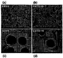
도 3은 본 발명에 따른 샘플 1과 비교 샘플 1의 전자 현미경 사진이다.
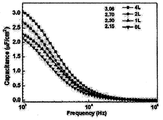
도 4는 본 발명에 따른 샘플 1 내지 3과 비교 샘플 2의 커패시턴스 측정 결과를 나타낸 그래프이다.
도 5는 본 발명에 따른 샘플 1 내지 3과 비교 샘플 2의 절연파괴전압 측정 결과를 나타낸 그래프이다.
이하, 첨부한 도면을 참조하여 본 발명의 실시예에 대해 상세히 설명한다. 본 발명은 다양한 변경을 가할 수 있고 여러 가지 형태를 가질 수 있는 바, 특정 실시예들을 도면에 예시하고 본문에 상세하게 설명하고자 한다. 그러나 이는 본 발명을 특정한 개시 형태에 대해 한정하려는 것이 아니며, 본 발명의 사상 및 기술 범위에 포함되는 모든 변경, 균등물 내지 대체물을 포함하는 것으로 이해되어야 한다. 각 도면을 설명하면서 유사한 참조부호를 유사한 구성요소에 대해 사용하였다.
본 출원에서 사용한 용어는 단지 특정한 실시 예를 설명하기 위해 사용된 것으로서 본 발명을 한정하려는 의도가 아니다. 단수의 표현은 문맥상 명백하게 다르게 뜻하지 않는 한, 복수의 표현을 포함한다. 본 출원에서, "포함하다" 또는 "가지다" 등의 용어는 명세서 상에 기재된 특징, 단계, 동작, 구성요소, 부분품 또는 이들을 조합한 것이 존재함을 지정하려는 것이지, 하나 또는 그 이상의 다른 특징들이나 단계, 동작, 구성요소, 부분품 또는 이들을 조합한 것들의 존재 또는 부가 가능성을 미리 배제하지 않는 것으로 이해되어야 한다.
다르게 정의되지 않는 한, 기술적이거나 과학적인 용어를 포함해서 여기서 사용되는 모든 용어들은 본 발명이 속하는 기술 분야에서 통상의 지식을 가진 자에 의해 일반적으로 이해되는 것과 동일한 의미를 가지고 있다. 일반적으로 사용되는 사전에 정의되어 있는 것과 같은 용어들은 관련 기술의 문맥 상 가지는 의미와 일치하는 의미를 가지는 것으로 해석되어야 하며, 본 출원에서 명백하게 정의하지 않는 한, 이상적이거나 과도하게 형식적인 의미로 해석되지 않는다.
도 1은 본 발명의 일 실시예에 따른 알루미늄 박의 제조 방법을 설명하기 위한 순서도이고, 도 2는 도 1의 제조 방법을 수행하기 위한 알루미늄 박의 제조 장치를 설명하기 위한 개념도이다.
도 1 및 도 2를 참조하면, 알루미늄 박의 제조 장치(200) 중의 진공 조건의 챔버(210)에서 알루미늄 박(TG)을 금속 산화물 졸(212)에 침지시킨다(단계 S110).
이때, 알루미늄 박(TG)은 표면에 형성된 다수의 에칭-포어들을 포함하는 상태로 금속 산화물 졸(212)에 침지된다.
구체적으로, 비어 있는 비진공 상태의 챔버(210) 내에 알루미늄 박(TG)을 배치시키고, 챔버(210) 내를 진공 상태로 만든다. 진공 상태로 만들면서, 알루미늄 박(TG)의 에칭-포어들 내부의 공기를 외부로 배출시킬 수 있다. 이때, 제조 장치(200)의 펌프(240)를 이용하여 챔버(210)를 진공 상태로 만들 수 있고, 펌프(240)와 챔버(210)를 연결하는 튜브에는 밸브가 설치될 수 있다. 진공 상태의 압력은 약 759 토르(Torr) 내지 1 밀리토르(mTorr)일 수 있다. 알루미늄 박 공극내부의 공기를 배출한다. 진공 상태에서, 알루미늄 박(TG)을 금속 산화물 졸(212)에 침지시킨다. 진공 상태를 만들면서, 알루미늄 박(TG)의 에칭-포어들 내부의 공기가 빠져나간 상태이므로 이 침지 공정에서 에칭-포어들 내부로 금속 산화물 졸(212)이 흡입되면서 에칭-포어들 내부의 내벽면이 금속 산화물 졸(212)로 균일하게 코팅될 수 있다.
금속 산화물 졸(212)은 금속 산화물로 이루어진 졸(sol) 상태의 코팅재로서, 예를 들어, 산화지르코늄(ZrO2), 산화티티늄(TiO2), 산화니오븀(Nb2O5), 산화탄탈(Ta2O5), 티탄산바륨(BaTiO3) 등을 들 수 있다. 이들은 각각 단독으로 또는 2 이상을 조합하여 이용할 수 있다. 금속 산화물 졸(212)은 금속 산화물의 전구체를 이용하여 제조할 수 있으며, 금속 산화물 졸(212)의 종류에 따라서 전구체 및 용매의 종류, 농도 및 첨가물의 종류, 배합비 등은 달라질 수 있다.
알루미늄 박(TG)은 챔버(210)에 구비된 지지부(214)에 설치되어 금속 산화물 졸(212)에 침지될 수 있다. 챔버(210)의 전면부는 내부의 코팅 상태를 확인할 수 있는 투명창을 포함하고, 챔버(210)에는 챔버(210) 내부의 압력 상태를 확인할 수 있는 압력 게이지(250)가 설치될 수 있다.
금속 산화물 졸(212)은 코팅재 공급부(220)에 저장된 후, 챔버(210)가 진공 상태가 된 후 공급유로를 통해 챔버(210)로 제공되어 챔버(210)의 내부 공간에 수용됨으로써 알루미늄 박(TG)을 침지시킬 수 있다. 이때, 상기 공급유로에는 밸브가 설치되어 금속 산화물 졸(212)의 유동을 개폐할 수 있다. 즉, 펌프(240)와 챔버(210)를 연결하는 튜브에 구비된 밸브를 닫고, 상기 공급유로와 연결된 밸브를 서서히 개방함으로써 압력 차이에 의해서 금속 산화물 졸(212)이 챔버(210) 내로 제공될 수 있고, 상기 공급유로와 연결된 밸브의 개방량을 통해서 챔버(210) 내의 금속 산화물 졸(212)의 액량을 조절할 수 있다.
금속 산화물 졸(212)에 알루미늄 박(TG)이 침지된 상태로 소정 시간을 유지시킨 후에, 잔여 금속 산화물 졸(212)을 회수하고(단계 S120), 알루미늄 박(TG)에 코팅된 금속 산화물 졸(212)을 건조시킨다(단계 S130).
상기 공급유로와 연결된 밸브를 닫아 금속 산화물 졸(212)의 공급을 중단한 상태에서, 챔버(210)과 공팅재 공급부(220) 사이에 연결된 배출유로와 연결된 밸브를 열어 상기 배출유로를 통해서 잔여 금속 산화물 졸(212)을 다시 코팅재 공급부(220)로 회수한다.
상기 배출유로를 통해서 금속 산화물 졸(212)이 배출되는 속도, 즉 금속 산화물 졸(212)이 챔버(210) 내에 잔존하는 높이를 기준으로, 10 mm/s 초과로 하는 경우, 담금 코팅(dip-coating)에서 알루미늄 박(TG)의 인상 속도가 증가되는 효과를 갖게 되어 알루미늄 박(TG)의 표면에 코팅되는 금속 산화물 졸(212)의 양이 증가하므로 두꺼운 두께의 코팅막이 형성될 수 있으나, 그 두께가 불균일하고 쉽게 균열이 생길 수 있는 단점이 있다. 따라서 금속 산화물 졸(212)이 배출되는 속도는 10 mm/s 이하인 것이 바람직하고, 약 0.2 mm/s 내지 약 10 mm/s일 수 있다.
이때, 잔여 금속 산화물 졸(212)을 회수하기 전에, 알루미늄 박(TG)을 금속 산화물 졸(212)에 침지시킨 상태에서 압력을 가하는 공정을 더 수행할 수 있다. 이 공정은, 금속 산화물 졸(212)의 코팅을 보다 균일하고 용이하게 진행하기 위해서 부가적으로 수행할 수 있는 공정으로서, 약 1 내지 5 기압 정도의 압력을 가할 수 있다. 약 10 분 내지 1 시간동안 가압 공정이 수행될 수 있다. 에칭-포어들의 깊이 및/또는 형상에 의해 코팅이 용이하지 않은 경우, 상기와 같이 가압을 해줌으로써 에칭-포어들 내부의 내벽에 균일하게 금속 산화물 졸(212)을 코팅시킬 수 있다. 에칭-포어들의 깊이가 10 ㎛를 초과하는 경우에는 가압 공정을 수행하는 것이 바람직하다. 가압 공정에서 이용되는 기체는, 불활성 가스로서, 아르곤(Ar), 헬륨(He) 등을 들 수 있다. 압력을 가한 후 일정시간(10~30분) 유지하여 코팅이 진행되도록 한다. 불활성 가스는 챔버(210)와 연결된 가스 공급부(230)를 통해서 제공될 수 있다.
상기에서 설명한 바와 같이, 잔여 금속 산화물 졸(212)을 회수하고, 건조 공정을 수행한다. 건조 공정은 약 100℃ 내지 200℃에서 수행될 수 있고, 약 30 내지 60분 동안 수행될 수 있다. 이에 따라 알루미늄 박(TG)의 표면, 특히 에칭-포어들 내부의 내벽면에 균일하게 금속 산화물 졸(212)이 코팅되어 코팅막을 형성할 수 있다. 상기 코팅막의 두께는, 침지 공정(S110), 회수 공정(S120) 및 건조 공정(130)을 포함하는 사이클 수를 조절함으로써 결정할 수 있다. 즉, 침지 공정(S110), 회수 공정(S120) 및 건조 공정(130)을 한 사이클로 하여, 이 사이클을 몇 번 수행하는지에 따라서 상기 코팅 두께가 결정될 수 있다. 이때, 상기 사이클에는 가압 공정이 더 추가될 수 있다.
이어서, 상기 코팅막이 형성된 알루미늄 박(TG)에 대해서 소결 공정을 수행하고(단계 S140), 소결된 알루미늄 박(TG)에 대해서 양극 산화 공정을 수행함으로써(단계 S150) 본 발명에 따른 알루미늄 박을 제조한다.
구체적으로, 소결 공정은 상기 코팅막을 결정화시키는 공정으로서, 약 350℃ 내지 약 600℃에서 수행될 수 있다. 이때, 소결 공정은 약 10분 내지 약 60분 동안 수행될 수 있다. 소결 공정은 대기압 또는 산소 분위기 하에서 수행될 수 있다.
일례로, 소결 공정은 상기에서 설명한 침지 공정(S110), 회수 공정(S120) 및 건조 공정(130)을 포함하는 사이클이 적어도 1회 이상 수행된 후에, 이어서 수행될 수 있다. 이와 달리, 소결 공정은 상기 사이클에 포함되어 사이클이 반복될 때마다 침지 공정(S110), 회수 공정(S120) 및 건조 공정(130)에 이어서 수행될 수 있다.
상기와 같이 소결 공정이 수행된 후, 소결된 알루미늄 박(TG)에 대해서는 양극 산화 공정이 수행되는데, 이때 양극 산화 공정은 약 100 V 내지 1000V의 전압으로 20 mA/cm2
내지 50 mA/cm2의 전류를 인가하여 알루미늄 박(TG)을 양극 산화시킬 수 있다. 특히, 알루미늄 박(TG)의 에칭-포어들 내부의 내벽면이 소정 두께로 산화되어 산화알루미늄으로 변환되고, 그 위에 코팅막이 금속 산화물층이 형성된 구조가 된다. 상기 코팅막이 균일한 두께를 가지고 알루미늄 박(TG)의 에칭-포어들 내부의 내벽면에 형성되어 있으므로 궁극적으로는 균일한 두께의 금속 산화물층이 상기 내벽면에 형성된 구조로서, 최종적으로 산화알루미늄과 고유전 상수를 갖는 금속 산화물층의 혼합층인 복합 산화물층을 포함하는 알루미늄 박이 형성된다. 이러한 알루미늄 박은 고전압용 전해 커패시터에 적용될 수 있다.
상기에서 설명한 바에 따르면, 다수의 에칭-포어들을 포함하는 다공성 알루미늄 박(TG)에 균일하게 유전 상수가 높은 금속 산화물층을 형성할 수 있다. 에칭-포어들을 통해서 전극의 유효 표면적을 증가시키면서도 동시에 산화알루미늄과 금속 산화물층을 모두 포함하는 복합 산화물층이 형성된 알루미늄 박을 제조할 수 있다. 이와 같은 알루미늄 박은 전극 구조체로서 전해질과 함께 전해 커패시터를 구성함으로써 동일 체적에서 정전 용량을 향상시킬 수 있다. 이에 따라, 알루미늄 전해 커패시터의 사이즈를 감소시킬 수 있어 제품의 시장 경쟁력을 향상시킬 수 있다. 즉, 2개의 전극 구조체들과 그들 사이에 개재된 전해질을 포함하는 전해 커패시터에 있어서, 적어도 1개의 전극 구조체가 본 발명에 따른 알루미늄 박으로 구성될 수 있다.
이하에서는, 구체적인 실시예들 및 비교예를 통해서 본 발명에 대해서 보다 구체적으로 설명하기로 한다.
실시예 1: 샘플 1의 제조
산화지르코늄의 전구체로서, 지르코늄 n-부톡사이드(Zirconium n-butoxide, [Zr[O(CH2)3CH3]4])를 이용하여 0.4 mol/ℓ 농도의 지르코니아 졸 용액을 제조하였다. 상기 지르코니아 졸 용액의 용매는 2-메톡시 에탄올(2-methoxy etanol, [CH3OCH2CH2OH])을 이용하였고, 첨가제는 초산(acetic acid[CH3COOH])을 사용하였다. 상기 지르코니아 졸 용액의 제조에서, 지르코늄과 아세트산의 몰비는 1:6이었고, 상온에서 60분간 교반한 후, 산화지르코늄의 침전을 방지하기 위해서 질산(HNO3)을 첨가하였다.
에칭-포어들이 형성된 알루미늄 박이 챔버 내에 배치된 상태에서 진공 조건(50 mTorr)을 만들고, 약 30분을 유지하여 에칭-포어들 내부의 공기를 배출시킨 후에 상기와 같이 준비된 지르코니아 졸 용액을 챔버로 공급하였다.
상기 지르코니아 졸 용액에 알루미늄 박이 침지된 상태로 15분 동안 유지시킨 후, 아르곤 가스로 3 기압의 압력을 가해 10분간 유지한 후 잔류 지르코니아 졸 용액을 0.5 mm/s로 하강하도록 조절하여 회수하였다. 이어서, 챔버를 개방한 후, 코팅막이 형성된 알루미늄 박을 100℃에서 1시간 건조하였다. 이와 같은, 침지, 가압 및 건조 공정을 4회 수행하였다.
500℃에서 30분간 소결 공정을 수행하여 코팅막을 결정화시키고, 증류수 1 ℓ에 붕산(H3BO3) 100 g을 혼합하여 제조된 pH 3.2의 양극 산화액으로 알루미늄 박을 양극 산화시켜 본 발명의 실시예 1에 따른 샘플 1을 제조하였다. 이때, 양극 산화에서는, 50 mA/cm2의 정전류를 인가하여 100 V까지 양극산화 처리함으로써 수행하였다.
비교예 1: 비교 샘플 1의 제조
에칭-포어들이 형성된 알루미늄 박을, 실시예 1에서의 금속 산화물 졸 용액에 담금 코팅 후 건조 및 양극 산화 공정을 수행하여 비교예에 따른 비교 샘플 1을 준비하였다.
실험 및 평가 1: 코팅 균일성 확인
샘플 1 및 비교 샘플 1 각각에 대해서, 표면층을 연마하여 전자 현미경으로 촬영하였다. 그 결과를 도 3에 나타낸다.
도 3은 본 발명에 따른 샘플 1과 비교 샘플 1의 전자 현미경 사진이다.
도 3에서, (a) 및 (c)는 비교 샘플 1의 전자 현미경 사진들이고, (b) 및 (d)는 샘플 1의 전자 현미경 사진들이다. 이때, (a) 및 (b)의 스케일은 1 ㎛이고, (c) 및 (d)의 스케일은 100 nm이다.
도 3을 참조하면, 단순히 담금 코팅을 통해서 제조한 비교 샘플 1의 경우에는 에칭-포어들의 내벽면에 불균일하게 지르코니아층이 형성된 것을 알 수 있다. (a)를 참조하면, 지르코니아층이 형성되지 않은 에칭-포어들도 확인되고 (c)를 참조하면 두께가 불균일함을 확인할 수 있다.
반면, 진공 상태의 챔버에서 가압 공정까지 수행한 경우에는 (b)에서와 같이 거의 대부분의 에칭-포어들의 내벽면에 지르코니아층이 형성된 것을 알 수 있다. 또한, (d)를 참조하면, 균일한 두께로 에칭-포어의 내벽면에 지르코니아층이 형성된 것을 알 수 있다.
실시예 2 및 3: 샘플 2 및 3의 제조
샘플 1을 제조하는 공정과 실질적으로 동일하되, 침지 공정, 가압 공정, 회수 공정 및 건조 공정을 포함하는 사이클을 1회 수행한 후 소결 및 양극 산화시켜 본 발명의 실시예 2에 따른 샘플 2를 제조하였다.
또한, 샘플 1을 제조하는 공정과 실질적으로 동일하되, 상기 사이클을 2회 수행한 후 소결 및 양극 산화시켜 본 발명의 실시예 3에 따른 샘플 3을 제조하였다.
비교예 2: 비교 샘플 2의 제조
에칭-포어들이 형성된 알루미늄 박을 100V에서 양극 산화시킨 것을 비교 샘플 2로서 준비하였다.
실험 및 평가 2: 커패시턴스 측정
본 발명에 따른 샘플 1 내지 3과 비교 샘플 2 각각에 대한 커패시턴스를 측정하였고, 그 결과를 도 4에 나타낸다. 도 4에서, "0L"은 비교 샘플 2에 대한 것이고, "4L", "1L" 및 "2L"각각은 샘플 1, 2 및 3에 대한 것이다.
도 4는 본 발명에 따른 샘플 1 내지 3과 비교 샘플 2의 커패시턴스 측정 결과를 나타낸 그래프이다.
도 4를 참조하면, 비교 샘플 2(0L)에 비해, 샘플 2(1L), 샘플 3(2L) 및 샘플 1(4L)로 점점 지르코니아층이 두꺼워질수록 비용량이 증가함을 알 수 있다. 특히, 샘플 1(4L)의 경우에는 비교 샘플 2(0L)에 비해서 주파수 1 kHz에서 약 42%의 용량증가를 보임을 확인할 수 있었다. 이는 동일한 용량의 콘덴서 제작시 약 40%의 알루미늄 박의 사용량을 줄일 수 있어 커패시터 제품이 소형화될 수 있음을 보이는 결과이다.
실험 및 평가 3: 내전압 측정
본 발명에 따른 샘플 1 내지 3과 비교 샘플 2 각각에 대한 내전압을 측정하였고, 그 결과를 도 5에 나타낸다. 도 5에서, "0L"은 비교 샘플 2에 대한 것이고, "4L", "1L" 및 "2L"각각은 샘플 1, 2 및 3에 대한 것이다.
도 5는 본 발명에 따른 샘플 1 내지 3과 비교 샘플 2의 내전압 측정 결과를 나타낸 그래프이다.
도 5를 참조하면, 100V로 양극 산화시킨 모든 샘플들, 즉, 샘플 1 내지 3 및 비교 샘플 2 모두에 있어 100 V 이상의 내전압을 나타내는 것을 알 수 있다. 즉, 지르코니아 유무에 상관없이 모두 커패시터에 적용하는데 문제가 없음을 알 수 있다.
상기에서 설명한 바에 따르면, 다수의 에칭-포어들을 포함하는 다공성 알루미늄 박(TG)에 균일하게 유전 상수가 높은 금속 산화물층을 형성할 수 있다. 에칭-포어들을 통해서 전극의 유효 표면적을 증가시키면서도 동시에 산화알루미늄과 금속 산화물층을 모두 포함하는 복합 산화물층이 형성된 알루미늄 박을 제조할 수 있다. 이와 같은 알루미늄 박은 전극 구조체로서 전해질과 함께 전해 커패시터를 구성함으로써 동일 체적에서 정전 용량을 향상시킬 수 있다. 이에 따라, 알루미늄 전해 커패시터의 사이즈를 감소시킬 수 있어 제품의 시장 경쟁력을 향상시킬 수 있다. 즉, 2개의 전극 구조체들과 그들 사이에 개재된 전해질을 포함하는 전해 커패시터에 있어서, 적어도 1개의 전극 구조체가 본 발명에 따른 알루미늄 박으로 구성될 수 있다.
상기에서는 본 발명의 바람직한 실시예를 참조하여 설명하였지만, 해당 기술 분야의 숙련된 당업자는 하기의 특허 청구 범위에 기재된 본 발명의 사상 및 영역으로부터 벗어나지 않는 범위 내에서 본 발명을 다양하게 수정 및 변경시킬 수 있음을 이해할 수 있을 것이다.
Claims (14)
- 진공 상태에서, 다수의 에칭-포어들을 포함하는 다공성 알루미늄 박을 챔버에 수용된 금속 산화물 졸에 함침시키는 함침 단계;상기 챔버 내에 잔류하는 금속 산화물 졸을 배출시키는 회수 단계;금속 산화물 졸이 코팅된 알루미늄 박을 건조시키는 건조 단계;건조된 코팅막을 소결시키는 소결 단계; 및소결된 코팅막이 형성된 알루미늄 박을 양극 산화시켜, 에칭-포어들 내부의 내벽면에 적층된 산화알루미늄층 및 금속 산화층을 포함하는 복합 산화물층을 형성하는 단계를 포함하는,알루미늄 박의 제조 방법.
- 제1항에 있어서,소결 단계를 수행하기 전 또는 소결된 알루미늄 박을 양극 산화시키기 전에, 함침 단계, 회수 단계 및 건조 단계를 포함하는 사이클을 반복하여 수행하는 것을 특징으로 하는,알루미늄 박의 제조 방법.
- 제1항에 있어서,회수 단계를 수행하기 전에, 알루미늄 박이 금속 산화물 졸에 함침된 상태에서 가압하는 가압 단계를 더 포함하는 것을 특징으로 하는,알루미늄 박의 제조 방법.
- 제3항에 있어서,소결 단계를 수행하기 전 또는 소결된 알루미늄 박을 양극 산화시키기 전에, 함침 단계, 가압 단계, 회수 단계 및 건조 단계를 포함하는 사이클을 반복하여 수행하는 것을 특징으로 하는,알루미늄 박의 제조 방법.
- 제1항에 있어서,상기 금속 산화물 졸에 함침시키는 단계는비진공 상태의 챔버 내에 알루미늄 박을 배치시키는 단계;알루미늄 박이 배치된 상태에서 챔버를 진공 상태로 만드는 단계; 및진공 상태의 챔버 내부로 금속 산화물 졸을 제공하는 단계를 포함하는 것을 특징으로 하는,알루미늄 박의 제조 방법.
- 제5항에 있어서,금속 산화물 졸을 수용하는 코팅재 공급부와 진공 상태의 챔버 사이의 압력 차에 의해서 상기 코팅재 공급부의 금속 산화물 졸이 챔버로 공급되는 것을 특징으로 하는,알루미늄 박의 제조 방법.
- 제1항에 있어서,상기 회수 단계는금속 산화물 졸의 배출 속도를 금속 산화물 졸이 챔버 내에서 수용된 높이를 기준으로 0.2 mm/s 내지 10 mm/s로 조절하는 것을 특징으로 하는,알루미늄 박의 제조 방법.
- 제1항에 있어서,상기 소결 단계는 350 ℃ 내지 600 ℃에서 수행되는 것을 특징으로 하는,알루미늄 박의 제조 방법.
- 제1항에 있어서,양극 산화는 100 V 내지 1000V의 전압까지 20 mA/cm2 내지 50 mA/cm2의 전류를 인가함으로써 수행하는 것을 특징으로 하는,알루미늄 박의 제조 방법.
- 다수의 에칭-포어들을 포함하는 다공성 알루미늄 박에 있어서,상기 에칭-포어들 내부의 내벽면에 형성된 알루미나층 상에 균일한 두께로 형성된 금속 산화물층을 포함하는 것을 특징으로 하는,알루미늄 박.
- 제10항에 있어서,상기 금속 산화물층의 두께 편차는 10% 이내인 것을 특징으로 하는,알루미늄 박.
- 제1 전극 구조체, 상기 제1 전극 구조체와 대향하는 제2 전극 구조체 및 상기 제1 전극 구조체와 상기 제2 전극 구조체 사이에 배치된 전해질을 포함하는 전해 커패시터에 있어서,상기 제1 전극 구조체 및 상기 제2 전극 구조체 중 적어도 하나는 에칭-포어들을 포함하는 다공성 알루미늄 박을 포함하되,상기 에칭-포어들 내부의 내벽면에 형성된 알루미나층 상에 균일한 두께로 형성된 금속 산화물층을 포함하는 것을 특징으로 하는,전해 커패시터.
- 다수의 에칭-포어들을 포함하는 다공성 알루미늄 박이 배치되는 챔버;상기 챔버로 금속 산화물 졸을 제공하는 코팅재 공급부; 및상기 챔버를 진공으로 만드는 펌프를 포함하는, 알루미늄 박의 제조 장치.
- 제13항에 있어서,상기 챔버와 연결되고, 알루미늄 박이 금속 산화물 졸에 함침된 상태에서 가압되도록 상기 챔버에 기체를 공급하는 기체 공급부를 더 포함하는 것을 특징으로 하는,알루미늄 박의 제조 장치.
Applications Claiming Priority (2)
| Application Number | Priority Date | Filing Date | Title |
|---|---|---|---|
| KR10-2015-0026906 | 2015-02-26 | ||
| KR1020150026906A KR101729382B1 (ko) | 2015-02-26 | 2015-02-26 | 전해 커패시터용 알루미늄 박의 제조 방법, 고유전 상수를 갖는 알루미늄 박, 이를 포함하는 전해 커패시터 및 알루미늄 박의 제조 장치 |
Publications (1)
| Publication Number | Publication Date |
|---|---|
| WO2016137057A1 true WO2016137057A1 (ko) | 2016-09-01 |
Family
ID=56789514
Family Applications (1)
| Application Number | Title | Priority Date | Filing Date |
|---|---|---|---|
| PCT/KR2015/005087 Ceased WO2016137057A1 (ko) | 2015-02-26 | 2015-05-21 | 전해 커패시터용 알루미늄 박의 제조 방법, 고유전 상수를 갖는 알루미늄 박, 이를 포함하는 전해 커패시터 및 알루미늄 박의 제조 장치 |
Country Status (2)
| Country | Link |
|---|---|
| KR (1) | KR101729382B1 (ko) |
| WO (1) | WO2016137057A1 (ko) |
Cited By (4)
| Publication number | Priority date | Publication date | Assignee | Title |
|---|---|---|---|---|
| CN107195489A (zh) * | 2017-04-21 | 2017-09-22 | 南通星晨电子有限公司 | 一种电容器电解液含浸装置 |
| CN113718310A (zh) * | 2021-08-09 | 2021-11-30 | 中南大学 | 一种高介电常数复合阳极氧化膜的制备方法 |
| CN114843108A (zh) * | 2022-05-18 | 2022-08-02 | 武汉理工大学 | 一种电极箔及其制备方法和应用 |
| WO2024027122A1 (zh) * | 2022-08-02 | 2024-02-08 | 南通海星电子股份有限公司 | 一种高介电复合粉末烧结箔的制备方法 |
Families Citing this family (1)
| Publication number | Priority date | Publication date | Assignee | Title |
|---|---|---|---|---|
| CN110379633B (zh) * | 2019-07-10 | 2021-10-08 | 益阳艾华富贤电子有限公司 | 一种固态电解电容器的含浸方法 |
Citations (5)
| Publication number | Priority date | Publication date | Assignee | Title |
|---|---|---|---|---|
| JPH0917685A (ja) * | 1995-06-27 | 1997-01-17 | Murata Mfg Co Ltd | コンデンサおよびその製造方法 |
| JP2005294401A (ja) * | 2004-03-31 | 2005-10-20 | Sanyo Electric Co Ltd | 固体電解コンデンサおよびその製造方法 |
| JP2006339177A (ja) * | 2005-05-31 | 2006-12-14 | Nichicon Corp | 固体電解コンデンサおよびその製造方法 |
| JP2008010490A (ja) * | 2006-06-27 | 2008-01-17 | Nichicon Corp | 電解コンデンサ用電極の製造方法 |
| KR101432138B1 (ko) * | 2012-09-26 | 2014-08-20 | 성균관대학교산학협력단 | 커패시터 및 이를 제조하는 제조방법 |
-
2015
- 2015-02-26 KR KR1020150026906A patent/KR101729382B1/ko active Active
- 2015-05-21 WO PCT/KR2015/005087 patent/WO2016137057A1/ko not_active Ceased
Patent Citations (5)
| Publication number | Priority date | Publication date | Assignee | Title |
|---|---|---|---|---|
| JPH0917685A (ja) * | 1995-06-27 | 1997-01-17 | Murata Mfg Co Ltd | コンデンサおよびその製造方法 |
| JP2005294401A (ja) * | 2004-03-31 | 2005-10-20 | Sanyo Electric Co Ltd | 固体電解コンデンサおよびその製造方法 |
| JP2006339177A (ja) * | 2005-05-31 | 2006-12-14 | Nichicon Corp | 固体電解コンデンサおよびその製造方法 |
| JP2008010490A (ja) * | 2006-06-27 | 2008-01-17 | Nichicon Corp | 電解コンデンサ用電極の製造方法 |
| KR101432138B1 (ko) * | 2012-09-26 | 2014-08-20 | 성균관대학교산학협력단 | 커패시터 및 이를 제조하는 제조방법 |
Cited By (5)
| Publication number | Priority date | Publication date | Assignee | Title |
|---|---|---|---|---|
| CN107195489A (zh) * | 2017-04-21 | 2017-09-22 | 南通星晨电子有限公司 | 一种电容器电解液含浸装置 |
| CN113718310A (zh) * | 2021-08-09 | 2021-11-30 | 中南大学 | 一种高介电常数复合阳极氧化膜的制备方法 |
| CN114843108A (zh) * | 2022-05-18 | 2022-08-02 | 武汉理工大学 | 一种电极箔及其制备方法和应用 |
| CN114843108B (zh) * | 2022-05-18 | 2023-11-14 | 武汉理工大学 | 一种电极箔及其制备方法和应用 |
| WO2024027122A1 (zh) * | 2022-08-02 | 2024-02-08 | 南通海星电子股份有限公司 | 一种高介电复合粉末烧结箔的制备方法 |
Also Published As
| Publication number | Publication date |
|---|---|
| KR101729382B1 (ko) | 2017-05-02 |
| KR20160104211A (ko) | 2016-09-05 |
Similar Documents
| Publication | Publication Date | Title |
|---|---|---|
| WO2016137057A1 (ko) | 전해 커패시터용 알루미늄 박의 제조 방법, 고유전 상수를 갖는 알루미늄 박, 이를 포함하는 전해 커패시터 및 알루미늄 박의 제조 장치 | |
| CN101552140B (zh) | 用于制造电极箔的方法 | |
| CN101689429B (zh) | 电极箔及其制造方法以及电解电容器 | |
| JP4973229B2 (ja) | 電解コンデンサおよびその製造方法 | |
| US20080123250A1 (en) | High energy density capacitors and methods of manufacture | |
| US8749955B2 (en) | Capacitor | |
| JP2019057703A (ja) | キャパシタ部品 | |
| TW533440B (en) | Method for forming titanium oxide film and titanium electrolytic capacitor | |
| WO2020174751A1 (ja) | 電解コンデンサ用電極箔、電解コンデンサおよびそれらの製造方法 | |
| Du et al. | Fabrication and characterization of the hierarchical AAO film and AAO-MnO2 composite as the anode foil of aluminum electrolytic capacitor | |
| US3397446A (en) | Thin film capacitors employing semiconductive oxide electrolytes | |
| CN1653566A (zh) | 具有高能量密度的电容器 | |
| US20090168299A1 (en) | Method for the production of a coating of a porous, electrically conductive support material with a dielectric, and production of capacitors having high capacity density with the aid of said method | |
| KR101806674B1 (ko) | 금속산화물로 코팅된 전해 커패시터용 알루미늄 박의 고전압 양극산화액 및 이를 이용한 전해 커패시터용 알루미늄 박의 제조 방법 | |
| WO2005101972A2 (en) | Integral separator for electrolytic capacitors | |
| JP5104008B2 (ja) | 電解コンデンサ | |
| JPH05315197A (ja) | 電解コンデンサ用アルミニウム電極の製造方法 | |
| JPH0475645B2 (ko) | ||
| KR101563433B1 (ko) | 커패시터 및 이의 제조 방법 | |
| JPH0653088A (ja) | 電解コンデンサ用アルミニウム電極とその製造方法 | |
| RU2391442C1 (ru) | Способ получения анодной фольги | |
| JP2003146659A (ja) | 複合チタン酸化被膜の形成方法およびチタン電解コンデンサ | |
| CN115335937B (zh) | 电解电容器用电极箔、电解电容器及电解电容器的制造方法 | |
| EP4715851A1 (en) | Capacitor, electrical circuit, circuit board, apparatus, member for capacitors, and method for manufacturing capacitor | |
| US20100046141A1 (en) | Method for coating a porous electrically conductive support material with a dielectric |
Legal Events
| Date | Code | Title | Description |
|---|---|---|---|
| 121 | Ep: the epo has been informed by wipo that ep was designated in this application |
Ref document number: 15883445 Country of ref document: EP Kind code of ref document: A1 |
|
| NENP | Non-entry into the national phase |
Ref country code: DE |
|
| 122 | Ep: pct application non-entry in european phase |
Ref document number: 15883445 Country of ref document: EP Kind code of ref document: A1 |