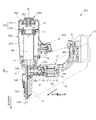
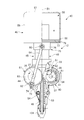
打込機201は、打ち込み対象たる釘11を打撃する打撃機構(シリンダ245、蓄圧容器250、ピストン47、ブレード48を含む)と、打撃機構を駆動するための動力を発生する電動モータ13と、電動モータ13の動力により打撃機構のブレード48を移動させる動力伝達機構と、電動モータ13に電力を供給する蓄電池15と、打撃機構の射出路へ釘11を1本ずつ供給すると共に射出される複数の釘11を保持するマガジン16を有する。釘11は細い丸棒又は角棒の先端を尖らせて後端をフランジ状に幅広くした止具であり、打込機201によって50~110mm程度の釘を打撃することができる。打撃機構は合成樹脂製で筒状の本体ハウジング202の内部に収容される。本体ハウジング202の側方には、作業者が片手で把持するためのグリップ203が設けられ、グリップ203の末端部には蓄電池15の装着部204が設けられる。蓄電池15は、装着部204に対して着脱可能とされる。装着部204には後述するコントローラ(制御部)を搭載するための制御回路基板81が収容される。
The driving machine 201 includes a hitting mechanism (including a cylinder 245, a pressure accumulating vessel 250, a piston 47, and a blade 48) that hits the nail 11 to be driven, an electric motor 13 that generates power for driving the hitting mechanism, A power transmission mechanism that moves the blade 48 of the striking mechanism by the power of the electric motor 13, a storage battery 15 that supplies power to the electric motor 13, and a plurality of nails 11 that are ejected while one nail 11 is fed to the ejection path of the striking mechanism. A magazine 16 for holding the nail 11 is provided. The nail 11 is a stopper having a narrow round bar or square bar with a sharp tip and a wide rear end in a flange shape. A nail of about 50 to 110 mm can be hit by the driving machine 201. The striking mechanism is made of synthetic resin and accommodated in the cylindrical main body housing 202. On the side of the main body housing 202, a grip 203 is provided for an operator to hold with one hand, and a mounting portion 204 for the storage battery 15 is provided at the end of the grip 203. The storage battery 15 can be attached to and detached from the mounting portion 204. The mounting portion 204 accommodates a control circuit board 81 for mounting a controller (control portion) described later.
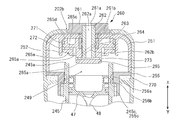
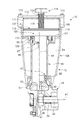
ピストン47の外周面にはシール部材55が取り付けられ、シリンダ245内で中心線B1に沿った軸方向に往復動可能である。ピストン47の下部には、釘11を打ち込むためであって軸方向に細長いブレード48が固定され、ピストン47の移動する空間の上部には空気を溜めておくための蓄圧容器250が設けられる。蓄圧容器250は、開口を下向きにした略カップ状の容器本体部251と、容器本体部251の開口部分を塞ぐと共に円筒状のシリンダ245への取付部が形成されるフランジ部255により形成される。蓄圧容器250の内部空間(空気圧室249)は、外部から取り込まれた空気を加圧された状態に維持する空気圧室249を有し、ピストン47によって空気が圧縮される空間(図2で後述するシリンダ室248)と流体的に接続されている。外部から空気圧室249に空気を取り込むために、蓄圧容器250の上部には外気取込み弁260が設けられる。外気取込み弁260の詳細については後述する。
A seal member 55 is attached to the outer peripheral surface of the piston 47, and can reciprocate in the axial direction along the center line B1 within the cylinder 245. An elongated blade 48 is fixed in the lower portion of the piston 47 in order to drive the nail 11 in the axial direction, and a pressure accumulating container 250 for storing air is provided in the upper portion of the space in which the piston 47 moves. The pressure accumulating container 250 is formed by a substantially cup-shaped container main body 251 with the opening facing downward, and a flange portion 255 that closes the opening of the container main body 251 and is formed with a mounting portion to the cylindrical cylinder 245. . The internal space (pneumatic chamber 249) of the pressure accumulating container 250 has a pneumatic chamber 249 that maintains the air taken in from outside in a pressurized state, and is a space in which air is compressed by the piston 47 (described later in FIG. 2). It is fluidly connected to the cylinder chamber 248). In order to take air into the air pressure chamber 249 from the outside, an outside air intake valve 260 is provided on the upper portion of the pressure accumulating vessel 250. Details of the outside air intake valve 260 will be described later.
蓄電池15は、収容ケースと、収容ケース内に収容した複数の電池セル(図示せず)とを有する。電池セルは、充電及び放電が可能な直流の二次電池であり、電池セルは、リチウムイオン電池、ニッケル水素電池、リチウムイオンポリマー電池、ニッケルカドミウム電池等を用いることができる。装着部204の一部はケーシング233に連続するモータハウジング17と接続される。ここでは本体ハウジング202、グリップ203、装着部204、ケーシング233、モータハウジング17がプラスチック等の合成樹脂製の成形品により製造され、ノーズ部254がアルミ合金又は鉄系の金属により製造され、これらの構成物が打込機201の筐体部分(広義のハウジング)を構成している。
The storage battery 15 has a storage case and a plurality of battery cells (not shown) stored in the storage case. The battery cell is a DC secondary battery that can be charged and discharged, and a lithium ion battery, a nickel hydrogen battery, a lithium ion polymer battery, a nickel cadmium battery, or the like can be used as the battery cell. A part of the mounting portion 204 is connected to the motor housing 17 continuing to the casing 233. Here, the main body housing 202, the grip 203, the mounting portion 204, the casing 233, and the motor housing 17 are manufactured by a molded product made of a synthetic resin such as plastic, and the nose portion 254 is manufactured by an aluminum alloy or an iron-based metal. The component constitutes a casing portion (broadly defined housing) of the driving machine 201.
電動モータ13はブラシレスDCモータであって、モータハウジング17に対して回転不能に固定されるステータ18と、ステータ18の内周側において回転可能に軸支されるロータ19と、を備えている。ステータ18は、積層鉄心からなるステータコアに通電用のコイル21を巻いたものである。ロータ19は、2個の軸受82a、82bにより支持された出力軸24と、出力軸24に固定されたロータコアと永久磁石を備えている。出力軸24は軸線A1を中心として回転可能である。電動モータ13の端部側には、略円環状のインバータ回路基板83が設けられ、後述するインバータ回路を形成するFET(電界効果トランジスタ)やIGBT(絶縁ゲートバイポーラトランジスタ)等の複数のスイッチング素子84が搭載される。また、インバータ回路基板83にはロータ19の回転位置を検出するためのホールIC等の磁気検出素子(図示せず)が設けられる。
The electric motor 13 is a brushless DC motor, and includes a stator 18 that is fixed to the motor housing 17 so as not to rotate, and a rotor 19 that is rotatably supported on the inner peripheral side of the stator 18. The stator 18 is obtained by winding a coil 21 for energization around a stator core made of a laminated iron core. The rotor 19 includes an output shaft 24 supported by two bearings 82a and 82b, a rotor core fixed to the output shaft 24, and a permanent magnet. The output shaft 24 is rotatable about the axis A1. A substantially annular inverter circuit board 83 is provided on the end side of the electric motor 13, and a plurality of switching elements 84 such as FETs (Field Effect Transistors) and IGBTs (Insulated Gate Bipolar Transistors) forming an inverter circuit described later. Is installed. The inverter circuit board 83 is provided with a magnetic detection element (not shown) such as a Hall IC for detecting the rotational position of the rotor 19.
電動モータ13の回転力は減速機27を介して駆動軸234に伝達される。減速機27としては公知の減速機構を用いることができるが、ここでは遊星歯車機構を2段直列に設けることにより出力軸24の回転数を十数分の一程度に減速して駆動軸234を回転させる。駆動軸234の端部には回転体238が固定され、駆動軸234に同期して回転する。回転体238は電動モータ13の動力により打撃機構のブレード48を移動させる動力伝達機構の一部を構成するもので、その構成や動作については図2~図4で後述する。
The rotational force of the electric motor 13 is transmitted to the drive shaft 234 via the speed reducer 27. A known speed reduction mechanism can be used as the speed reducer 27, but here, the planetary gear mechanism is provided in two stages in series to reduce the rotational speed of the output shaft 24 to about one-tenth and to drive the drive shaft 234. Rotate. A rotating body 238 is fixed to the end of the drive shaft 234 and rotates in synchronization with the drive shaft 234. The rotating body 238 constitutes a part of a power transmission mechanism that moves the blade 48 of the striking mechanism by the power of the electric motor 13, and the configuration and operation thereof will be described later with reference to FIGS.
ノーズ部254は、本体ハウジング202の射出方向側に取り付けられるものであり、射出される釘11の射出路を形成する。ノーズ部254には、その先端部分を覆うようにしてプッシュロッド104が設けられている。プッシュロッド104は、ノーズ部254に対して射出方向と同方向及び反対方向に所定の範囲で移動可能であって、打ち込み動作を行う際に用いられる一種の安全装置である。打込機201は、釘11の打ち込みの際に作業者がプッシュロッド104を釘11の打ち込む対象物(被打込み材)に押し当てた状況でなければトリガ(トリガレバー)72を引いても電動モータ13が回転しないように制御される。プッシュロッド104は、射出方向の先端側が何にも接触していないときには圧縮バネ105によって付勢され、射出方向側に位置する。作業者がプッシュロッド104を対象物に押し付けると、圧縮バネ105の力に抗してプッシュロッド104は反射出方向に移動して停止する。プッシュロッド104が後退すると図示しない押し付け検知スイッチがオンになり、その出力が後述するコントローラに伝達される。コントローラはプッシュロッド104が押された状態とトリガ72が引かれた状態の双方が成り立ったときのみ、電動モータ13の起動を許容する。
The nose portion 254 is attached to the injection direction side of the main body housing 202 and forms an injection path for the nail 11 to be injected. The nose portion 254 is provided with a push rod 104 so as to cover the tip portion thereof. The push rod 104 is a kind of safety device that is movable in a predetermined range in the same direction as the injection direction and in the opposite direction with respect to the nose portion 254, and is used when performing a driving operation. The driving machine 201 is electrically driven even when the trigger (trigger lever) 72 is pulled unless the operator presses the push rod 104 against the object (target material to be driven) of the nail 11 when the nail 11 is driven. Control is performed so that the motor 13 does not rotate. The push rod 104 is biased by the compression spring 105 when the tip end side in the injection direction is not in contact with anything, and is located on the injection direction side. When the operator presses the push rod 104 against the object, the push rod 104 moves in the reflecting direction and stops against the force of the compression spring 105. When the push rod 104 moves backward, a pressing detection switch (not shown) is turned on, and the output is transmitted to a controller described later. The controller allows the electric motor 13 to start only when both the state where the push rod 104 is pushed and the state where the trigger 72 is pulled are satisfied.
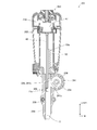
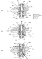
図2は図1のA方向から見た矢視図であって、ピストン47が下死点にある時の状態を示す。本実施例では、ピストン47をシリンダ45内において空気圧室249の圧力を増加させる方向に移動させる移動機構を有する。この移動機構は、電動モータ13の駆動力によって回転する回転体238と、ラック53を有するブレード48により主に構成される。ここでは、外周縁の一部にピニオン(ギヤ)241を有する回転体238を回転させ、ブレード48の長手方向側面に形成されたラック53にピニオン241をかみ合わせることにより、ピストン47を下死点から上死点まで移動させる。回転体238とピニオン241は金属製の一体品で形成され、駆動軸234の回転によって回転体238は、矢印242の方向に又はその反対方向に回転可能である。ピニオン241は、回転体238の外縁部分において、回転角にして約270度分だけ配置される。従って、回転体238が回転すると、ピニオン241の先端歯241aがラック53の上端歯53aとの噛合を開始することにより、ブレード48を上方に移動させることができ、これによりブレード48に固定されたピストン47も上死点側に向けて移動させることができる。
FIG. 2 is an arrow view seen from the direction A in FIG. 1 and shows a state when the piston 47 is at the bottom dead center. In this embodiment, there is a moving mechanism for moving the piston 47 in the cylinder 45 in the direction of increasing the pressure of the pneumatic chamber 249. This moving mechanism is mainly composed of a rotating body 238 that rotates by the driving force of the electric motor 13 and a blade 48 having a rack 53. Here, the rotating body 238 having a pinion (gear) 241 at a part of the outer peripheral edge is rotated, and the pinion 241 is engaged with the rack 53 formed on the longitudinal side surface of the blade 48, whereby the piston 47 is bottom dead centered. To top dead center. The rotating body 238 and the pinion 241 are formed as a single piece of metal, and the rotating body 238 can be rotated in the direction of the arrow 242 or in the opposite direction by the rotation of the drive shaft 234. The pinion 241 is disposed at the outer edge portion of the rotating body 238 by a rotation angle of about 270 degrees. Accordingly, when the rotating body 238 rotates, the tip teeth 241a of the pinion 241 start to engage with the upper end teeth 53a of the rack 53, so that the blade 48 can be moved upward, thereby being fixed to the blade 48. The piston 47 can also be moved toward the top dead center.
図3は回転体238を図2の状態から矢印242の方向に約300度回転した状態を示す図であり、ラック53とすべてのピニオン241の噛合が終わってラック53の下端歯53bとピニオン241の後端歯241bの噛合がまさに外れる直前の状態を示している。ブレード48の先端48bが射出路256を上方側に移動すると、マガジン16から次に打ち込まれる釘11が射出路256内に給送される。図3の状態の直後、つまりピストン47が上死点に到達したら、ピニオン241の後端歯241bとラック53下端歯53bとの接触状態が解除されるため、空気圧室249内の空気を圧縮していたピストン47を支える力が無くなり、ピストン47は空気圧室の圧縮された空気の反発力により下死点に向けて急激に移動を開始する。この時点ではブレード48の先端48bの直下に、頭頂部11aがくるようにマガジン16によって釘11が装填済みなので、ブレード48は釘11を物体に打ち込むことができる。
FIG. 3 is a view showing a state where the rotating body 238 is rotated about 300 degrees from the state of FIG. 2 in the direction of the arrow 242, and the meshing of the rack 53 and all the pinions 241 is completed and the lower end teeth 53 b of the rack 53 and the pinions 241 are shown. A state immediately before the rear end teeth 241b are disengaged is shown. When the tip 48 b of the blade 48 moves upward in the injection path 256, the nail 11 to be driven next from the magazine 16 is fed into the injection path 256. Immediately after the state of FIG. 3, that is, when the piston 47 reaches the top dead center, the contact state between the rear end teeth 241b of the pinion 241 and the lower end teeth 53b of the rack 53 is released, so that the air in the pneumatic chamber 249 is compressed. The force which supported the piston 47 which had been lost is lost, and the piston 47 starts to move toward the bottom dead center due to the repulsive force of the compressed air in the pneumatic chamber. At this time, since the nail 11 has been loaded by the magazine 16 so that the top 11a is located immediately below the tip 48b of the blade 48, the blade 48 can drive the nail 11 into the object.
図4は図3の後の状態であって釘11の打ち込みが完了したあとのノーズ部254を、図1のA方向と反対側から見た矢視図である。釘11の打撃時には、電動モータ13は回転しているため駆動軸234も回転を続けている。しかしながら、回転体238の周方向の1カ所に、駆動軸234と平行して設けられる円柱状のピン235が設けられ、釘11の打ち込みが終わったタイミングでピン235がオフスイッチ236に作用する。オフスイッチ236はノーズ部254の側面に設けられ、その出力がコントローラに接続され、釘11が射出されたタイミングで出力パルスを伝達する。オフスイッチ236の近傍にはプランジャ236aを操作するための操作レバー237が設けられる。回転体238が回転することによりピン235の位置も周方向に移動する。操作レバー237はバネ材等の弾力性を有する金属薄板にて製造されたもので、先端に半円筒状に曲げた部分を有する。回転体238が矢印242の方向に回転すると、駆動軸234と平行に設けられたピン235が操作レバー237の半円筒部に当接し、操作レバー237がピン235に押されて変形することによってオフスイッチ236のプランジャ236aが押される。この押された時点では釘11の打ち込みが完了したあとなので、後述するコントローラはオフスイッチ236の出力信号を受けると電動モータ13への駆動電力の供給を停止する。プランジャ236aが押された後は、操作レバー237とピン235の当接状態が解除されるので、駆動軸234も停止し、回転体238が図4の位置にて停止する。なお、釘11が打ち込まれた時点では、ラック53とピニオン241は非接触状態にある。
4 is an arrow view of the nose portion 254 after the driving of the nail 11 is completed, as viewed from the side opposite to the direction A in FIG. When the nail 11 is hit, the drive shaft 234 continues to rotate because the electric motor 13 is rotating. However, a cylindrical pin 235 provided in parallel with the drive shaft 234 is provided at one place in the circumferential direction of the rotating body 238, and the pin 235 acts on the off switch 236 at the timing when the nail 11 is driven. The off switch 236 is provided on the side surface of the nose portion 254, and its output is connected to the controller and transmits an output pulse at the timing when the nail 11 is ejected. In the vicinity of the off switch 236, an operation lever 237 for operating the plunger 236a is provided. As the rotating body 238 rotates, the position of the pin 235 also moves in the circumferential direction. The operation lever 237 is made of a thin metal plate having elasticity such as a spring material, and has a semi-cylindrical bent portion at the tip. When the rotating body 238 rotates in the direction of the arrow 242, the pin 235 provided in parallel with the drive shaft 234 comes into contact with the semi-cylindrical portion of the operation lever 237, and the operation lever 237 is pushed by the pin 235 and deformed to turn off. The plunger 236a of the switch 236 is pushed. Since the nail 11 has been driven in at this point, the controller, which will be described later, stops supplying drive power to the electric motor 13 when receiving the output signal of the off switch 236. After the plunger 236a is pushed, the contact state between the operation lever 237 and the pin 235 is released, so that the drive shaft 234 is also stopped and the rotating body 238 is stopped at the position shown in FIG. Note that when the nail 11 is driven, the rack 53 and the pinion 241 are in a non-contact state.
釘11が正しく打撃されたか、ブレード48が正しい位置で停止したかは磁気センサ257を用いて検出することができる。磁気センサ257はノーズ部254に取り付けられ、ピストン47が下死点にまで移動した際のラック53の下端歯53bと隣接する歯の間の位置に設けられる。磁気センサ257は、ラック53の磁気センサ257側に突出する歯の接近によってコントローラに信号を送出するものである。尚、図4では模式的に図示したので、磁気センサ257が大きいが、実際にはノーズ部254に内蔵させるように小型化して、リード線も目立たないように配線するものである(よって図1~図3では図示していない)。ピストン47が下死点まで移動すると、ブレード48の下端歯53bだけが磁気センサ257の前を横切るので、磁気センサ257からコントローラに対して1パルス分の出力信号が送られる。よって、コントローラはこの出力信号の有無でブレード48が射出位置まで移動したかを正しく識別できる。この停止した状態は、ピストン47が下死点にある位置なので、作業者がプッシュロッド104を一旦開放してから、次の打撃位置にて再度プッシュロッド104を押しつけてトリガ72を引くことにより、次の打撃動作を開始できる。釘づまりが起きた場合は、磁気センサ257の前をブレード48の下端歯53bが通過しない。これにより、釘づまりを検出したら蓄圧室内の圧力を放出し、放出後に作業者は詰まった釘を取除く作業を行う。
Whether the nail 11 has been hit correctly or whether the blade 48 has stopped at the correct position can be detected using the magnetic sensor 257. The magnetic sensor 257 is attached to the nose portion 254, and is provided at a position between the lower end tooth 53b of the rack 53 and the adjacent tooth when the piston 47 moves to the bottom dead center. The magnetic sensor 257 sends a signal to the controller when a tooth protruding toward the magnetic sensor 257 side of the rack 53 approaches. Since the magnetic sensor 257 is large because it is schematically illustrated in FIG. 4, the magnetic sensor 257 is actually reduced in size so as to be incorporated in the nose portion 254 and wired so that the lead wire is not conspicuous (therefore, FIG. 1). (Not shown in FIG. 3). When the piston 47 moves to the bottom dead center, only the lower end tooth 53b of the blade 48 crosses the front of the magnetic sensor 257, so that an output signal for one pulse is sent from the magnetic sensor 257 to the controller. Therefore, the controller can correctly identify whether the blade 48 has moved to the injection position with or without the output signal. Since this stopped state is a position where the piston 47 is at the bottom dead center, the operator once opens the push rod 104 and then pushes the push rod 104 again at the next striking position to pull the trigger 72. The next striking action can be started. When the clogging occurs, the lower end teeth 53b of the blade 48 do not pass in front of the magnetic sensor 257. As a result, when the nail clogging is detected, the pressure in the pressure accumulating chamber is released, and after the release, the operator removes the clogged nail.
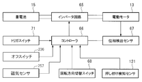
図5は本実施例の打込機201の制御ブロック図である。インバータ回路65は蓄電池15による直流電流から電動モータ13を駆動するための3相交流電流(励磁電流)を生成する回路であり、電動モータ13の後端側に設けられたインバータ回路基板83(図1参照)に搭載される。インバータ回路65は、電動モータ13のステータ18のコイルに接続された6つのスイッチング素子84(図1参照)を備え、複数のスイッチング素子84のオンオフがコントローラ66によって制御される。コントローラ66は釘11の打撃時(第2工程)の電動モータ13の回転制御をすると共に、電動モータ13を用いた空気圧室249の加圧(第1工程)時の回転制御を行う。コントローラ66には、図示しないマイクロコンピュータ(以下、「マイコン」と称す)を含んで構成される。電動モータ13には、ロータ19の回転方向の位相を検出する位相検出センサ67が設けられている。位相検出センサ67は、電動モータ13のロータ19に含まれる永久磁石の磁界を検出する複数のホールIC等を含んで実現でき、コントローラ66は、位相検出センサ67の信号に基づいて、ロータ19の回転方向の位置及び回転数を求めることができる。コントローラ66は、位相検出センサ67の信号及び減速機27の変速比に基づいて、回転体38の回転方向の位置、つまり、回転角度を推定する。
FIG. 5 is a control block diagram of the driving machine 201 of this embodiment. The inverter circuit 65 is a circuit that generates a three-phase alternating current (excitation current) for driving the electric motor 13 from the direct current from the storage battery 15, and an inverter circuit board 83 (see FIG. 5) provided on the rear end side of the electric motor 13. 1). The inverter circuit 65 includes six switching elements 84 (see FIG. 1) connected to the coil of the stator 18 of the electric motor 13, and on / off of the plurality of switching elements 84 is controlled by the controller 66. The controller 66 controls the rotation of the electric motor 13 at the time of hitting the nail 11 (second process) and also performs the rotation control at the time of pressurization (first process) of the pneumatic chamber 249 using the electric motor 13. The controller 66 includes a microcomputer (not shown) (hereinafter referred to as “microcomputer”). The electric motor 13 is provided with a phase detection sensor 67 that detects the phase in the rotational direction of the rotor 19. The phase detection sensor 67 can be realized by including a plurality of Hall ICs or the like that detect the magnetic field of the permanent magnet included in the rotor 19 of the electric motor 13. The controller 66 is based on the signal from the phase detection sensor 67. The position and the number of rotations in the rotation direction can be obtained. Based on the signal from the phase detection sensor 67 and the gear ratio of the speed reducer 27, the controller 66 estimates the position in the rotational direction of the rotating body 38, that is, the rotational angle.
電動モータ13のロータ19の回転方向を切り替える回転方向切替スイッチ68が設けられている。回転方向切替スイッチ68は、作業者により操作される。回転方向切替スイッチ68は正回転及び逆回転の操作位置がある。さらに、釘11の打ち込み完了を検出するオフスイッチ236と、ブレード48が下死点に達したか否かを検出する磁気センサ257の信号がコントローラ66に入力される。コントローラ66は、位相検出センサ67から入力される信号を処理して、ピストン47のシリンダ46の中心線B1方向の位置を推定する。トリガスイッチ71は(図1参照)は、作業者がトリガ72(図1参照)を操作することによりオンオフされるスイッチ機構である。トリガスイッチ71の信号はコントローラ66へ入力される。さらに、プッシュロッド104が物体に押し付けられているか否かを検知する押し付け検知センサ121が設けられており、押し付け検知センサ121から出力される信号は、コントローラ66へ入力される。コントローラ66は、これらのスイッチ及びセンサの信号に基づいて、電動モータ13の回転、停止、回転数、回転方向を制御する。
A rotation direction changeover switch 68 that switches the rotation direction of the rotor 19 of the electric motor 13 is provided. The rotation direction changeover switch 68 is operated by an operator. The rotation direction changeover switch 68 has forward and reverse operation positions. Further, an off switch 236 that detects the completion of driving of the nail 11 and a signal from the magnetic sensor 257 that detects whether or not the blade 48 has reached bottom dead center are input to the controller 66. The controller 66 processes the signal input from the phase detection sensor 67 to estimate the position of the piston 47 in the direction of the center line B1 of the cylinder 46. The trigger switch 71 (see FIG. 1) is a switch mechanism that is turned on and off by an operator operating the trigger 72 (see FIG. 1). A signal from the trigger switch 71 is input to the controller 66. Further, a pressing detection sensor 121 that detects whether or not the push rod 104 is pressed against the object is provided, and a signal output from the pressing detection sensor 121 is input to the controller 66. The controller 66 controls the rotation, stop, rotation speed, and rotation direction of the electric motor 13 based on signals from these switches and sensors.
次に、打込機10の動作及び制御を説明する。コントローラ66は、トリガスイッチ71がオンされると、インバータ回路65を制御してコイル21に電流を供給し、電動モータ13のロータ19を回転させる。コントローラ66は、回転方向切替スイッチ68の信号に基づいて、コイル21に流す電流の向きを制御し、ロータ19の回転方向を決定する。また、コントローラ66は、位相検出センサ67の信号に基づいて、ロータ19の回転方向の位置を検出し、インバータ回路65のスイッチング素子をオンオフするタイミング及びスイッチング素子のオン割合、つまり、デューティ比を制御する。このようにして、ロータ19の単位時間当たりの回転数が制御される。電動モータ13は、コイル21に対する電流の供給向きを切り替えることにより、ロータ19の回転方向を正回転と逆回転とに切り替え可能である。ロータ19が回転すると、出力軸24の回転力は、減速機27を経由して駆動軸234に伝達される。
Next, the operation and control of the driving machine 10 will be described. When the trigger switch 71 is turned on, the controller 66 controls the inverter circuit 65 to supply current to the coil 21 and rotate the rotor 19 of the electric motor 13. The controller 66 controls the direction of the current flowing through the coil 21 based on the signal from the rotation direction changeover switch 68 and determines the rotation direction of the rotor 19. Further, the controller 66 detects the position of the rotor 19 in the rotational direction based on the signal of the phase detection sensor 67, and controls the timing for turning on / off the switching element of the inverter circuit 65 and the ON ratio of the switching element, that is, the duty ratio. To do. In this way, the number of rotations of the rotor 19 per unit time is controlled. The electric motor 13 can switch the rotation direction of the rotor 19 between forward rotation and reverse rotation by switching the direction of current supply to the coil 21. When the rotor 19 rotates, the rotational force of the output shaft 24 is transmitted to the drive shaft 234 via the speed reducer 27.
打込機10を使用して打撃を行う場合には、必要ならば事前に空気圧室249内の空気圧を上昇させる第1工程を行う。第1工程は打撃作業開始前の準備工程であり、空気圧室249の圧力が低くなった場合にだけ行えば良く(例えば数週間~数ヶ月毎)、通常はいきなり第2工程(通常の打ち込み動作)から実行できる。第2工程において、作業者はプッシュロッド104を物体に押し付け、かつ、トリガ72を引くと空気圧室249内の空気圧がさらに上昇して釘11が打撃される。
When hitting using the driving machine 10, the first step of increasing the air pressure in the air pressure chamber 249 is performed in advance if necessary. The first step is a preparatory step prior to the start of the striking work, and should be performed only when the pressure in the pneumatic chamber 249 becomes low (for example, every few weeks to several months). Usually, the second step (normal driving operation) ) Can be executed. In the second step, when the operator presses the push rod 104 against the object and pulls the trigger 72, the air pressure in the air pressure chamber 249 further increases and the nail 11 is hit.
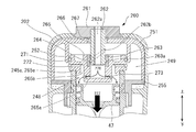
次に、第1工程における空気圧室249の圧力を上昇させる手順を図6~図8を用いて説明する。図6~図8は、図1の蓄圧容器250に設けた外気取込み弁260付近の部分拡大図である。図6は外気取込み弁260が閉じられた状態であって、外気の蓄圧容器250への取り入れが禁止されている状態を示している。外気取込み弁260は蓄圧容器250の上側に設けられた貫通穴251bを貫通させるように設けられる開閉弁機構であって、開状態(図7、図8)にて外気から空気圧室249側への空気の流入を許容し、閉状態(図6)においては外気と空気圧室249内との空気の流れを完全に遮断する。蓄圧容器250は合成樹脂製の本体ハウジング202の内部に収容され、フランジ部255の下側にはクッション材270を設けて蓄圧容器250ががたつかないように保持される。シリンダ245とフランジ部255の円筒部分は、シリンダ245側に形成した雄ねじ245cと、フランジ部255の内周側に形成した雌ねじ255cにより螺合され、さらに、螺合部分の上側に2つのOリング256a、256bを介在させて機密性を高めている。
Next, the procedure for increasing the pressure in the pneumatic chamber 249 in the first step will be described with reference to FIGS. 6 to 8 are partially enlarged views of the vicinity of the outside air intake valve 260 provided in the pressure accumulating vessel 250 of FIG. FIG. 6 shows a state in which the outside air intake valve 260 is closed, and intake of outside air into the pressure accumulating vessel 250 is prohibited. The outside air intake valve 260 is an on-off valve mechanism that is provided so as to pass through a through hole 251b provided on the upper side of the pressure accumulating vessel 250, and from the outside air to the pneumatic chamber 249 side in the open state (FIGS. 7 and 8). Inflow of air is allowed, and in the closed state (FIG. 6), the air flow between the outside air and the pneumatic chamber 249 is completely blocked. The pressure accumulating container 250 is accommodated inside the synthetic resin main body housing 202, and a cushion material 270 is provided below the flange portion 255 so as to prevent the pressure accumulating container 250 from rattling. The cylinder portion of the cylinder 245 and the flange portion 255 is screwed by a male screw 245c formed on the cylinder 245 side and a female screw 255c formed on the inner peripheral side of the flange portion 255, and further, two O-rings are provided above the screwed portion. The confidentiality is enhanced by interposing 256a and 256b.
外気取込み弁260は、弁機構の主構成部品となるセレクタ265と、セレクタ265を保持すると共に軸方向(軸線B1方向)に移動させるための円筒スリーブ262と、円筒スリーブ262の回転力をセレクタ265の軸方向への移動力に変換させる可動機構(264と図7に示す262b、263a)と、円筒スリーブ262を回転させるための切替レバー261を含んで構成される。切替レバー261は本体ハウジング202の上部に開けられた貫通穴202bの内部に配置されるノブであって、中央に外気取入通路262aが形成された中空の円筒スリーブ262を固定する。切替レバー261の上部中央にも貫通穴261aが形成され外気取入通路262aと連通する。円筒スリーブ262は容器本体部251に形成された貫通穴にリング状のメタル266を取り付け、メタル266によりB1軸方向に移動可能なように保持される。切替レバー261と円筒スリーブ262の間には、ワッシャ267が介在される。円筒スリーブ262の下側にはセレクタ265が設けられる。セレクタ265は回転しながら軸方向に移動可能なように構成され、円筒スリーブ262の外周側に当接するカップ状の内壁面を有する。カップ状の内壁面の底部(下側面)付近には、カップ状の内側部分とセレクタ265の外側部分を連通させるための連通路265aが形成される。連通路265aはセレクタ265の軸心から径方向外側に延びる2本又は複数本の貫通穴であって、円筒スリーブ262の下端部がセレクタ265の底面部から離れた際に、連通路265aによって外気取入通路262aと空気圧室249が連通可能となる。連通路265aの外周側出口は、円周方向に連続するように溝部が形成され、溝部にはゴム製のOリング273が配置される。Oリング273は逆止弁の機能を果たし、空気圧室249側から連通路265a側への空気の流れが遮断され、逆に、空気の圧力差がある場合には連通路265a側から空気圧室249側への空気の流れが許容される。シリンダ245にはさらに、円筒状に下から上方向への円筒窪み265bと、円筒窪み265bから径方向外側に延びる2本又は複数本の連通路265cが形成される。連通路265cの外周側出口は、円周方向に連続するように溝部が形成され、溝部にはゴム製であって逆止弁の機能を果たすOリング272が配置される。
The outside air intake valve 260 includes a selector 265 that is a main component of the valve mechanism, a cylindrical sleeve 262 that holds the selector 265 and moves it in the axial direction (in the direction of the axis B1), and the rotational force of the cylindrical sleeve 262 is selected by the selector 265. 7 includes a movable mechanism (264 and 262b and 263a shown in FIG. 7) that converts the moving force in the axial direction of the shaft, and a switching lever 261 for rotating the cylindrical sleeve 262. The switching lever 261 is a knob disposed inside a through hole 202b opened in the upper portion of the main body housing 202, and fixes a hollow cylindrical sleeve 262 having an outside air intake passage 262a formed in the center. A through hole 261a is also formed in the upper center of the switching lever 261 and communicates with the outside air intake passage 262a. The cylindrical sleeve 262 has a ring-shaped metal 266 attached to a through hole formed in the container main body 251 and is held by the metal 266 so as to be movable in the B1 axis direction. A washer 267 is interposed between the switching lever 261 and the cylindrical sleeve 262. A selector 265 is provided below the cylindrical sleeve 262. The selector 265 is configured to be movable in the axial direction while rotating, and has a cup-shaped inner wall surface that contacts the outer peripheral side of the cylindrical sleeve 262. In the vicinity of the bottom (lower side) of the cup-shaped inner wall surface, a communication path 265 a for communicating the cup-shaped inner portion and the outer portion of the selector 265 is formed. The communication path 265a is two or more through holes extending radially outward from the axis of the selector 265. When the lower end of the cylindrical sleeve 262 is separated from the bottom surface of the selector 265, the communication path 265a The intake passage 262a and the pneumatic chamber 249 can communicate with each other. A groove portion is formed at the outer peripheral side outlet of the communication path 265a so as to be continuous in the circumferential direction, and a rubber O-ring 273 is disposed in the groove portion. The O-ring 273 functions as a check valve, and the flow of air from the air pressure chamber 249 side to the communication path 265a side is blocked. Conversely, when there is an air pressure difference, the air pressure chamber 249 from the communication path 265a side. Air flow to the side is allowed. The cylinder 245 is further formed with a cylindrical recess 265b from the bottom to the top in a cylindrical shape, and two or a plurality of communication passages 265c extending radially outward from the cylindrical recess 265b. A groove portion is formed at the outer peripheral side outlet of the communication passage 265c so as to be continuous in the circumferential direction, and an O-ring 272 made of rubber and serving as a check valve is disposed in the groove portion.
円筒スリーブ262の回転力をセレクタ265の軸方向への移動力に変換させる可動機構には、セレクタ265の内周側に設けられるカラー263とスチールボール264が含まれる。カラー263の内周面には、半球状の窪み263a(図7参照)が形成される。円筒スリーブ262の外周面には、周方向及び軸方向に変化しながら回転角で180度分形成されたスプライン溝262bが形成される。スプライン溝262bと窪み263aの間にはスチールボール264が配置される。作業者が切替レバー261を周方向に約180度回転させると、その回転に伴い円筒スリーブ262も回転する。すると、スチールボール264が、斜めに配置されたスプライン溝262bに案内されることによりカラー263が軸方向下側に移動する。この移動後の状態を示すのが図7のセレクタ265の状態である。
The movable mechanism that converts the rotational force of the cylindrical sleeve 262 into the moving force in the axial direction of the selector 265 includes a collar 263 and a steel ball 264 provided on the inner peripheral side of the selector 265. A hemispherical recess 263a (see FIG. 7) is formed on the inner peripheral surface of the collar 263. On the outer peripheral surface of the cylindrical sleeve 262, a spline groove 262b is formed which is formed by a rotation angle of 180 degrees while changing in the circumferential direction and the axial direction. A steel ball 264 is disposed between the spline groove 262b and the recess 263a. When the operator rotates the switching lever 261 about 180 degrees in the circumferential direction, the cylindrical sleeve 262 also rotates with the rotation. Then, the collar 263 moves downward in the axial direction by the steel ball 264 being guided by the spline groove 262b disposed obliquely. The state after this movement is the state of the selector 265 in FIG.
図7において可動機構によりセレクタ265は下方に移動し、セレクタ265の下側に形成された段差部265eがシリンダ245の上端の開口部245aに密接することにより、空気圧室249とシリンダ室248の空間を分離する。この際、セレクタ265の上側外周溝265d(図6参照)に配置されるOリング271は容器本体部251の内周側に形成された円筒部252の内壁部分に当接しているため、空気圧室249は外気あるいはシリンダ室248とは密閉された状態で保たれる。このOリング272によりシリンダ室248から空気圧室249側への空気の流れだけが許容される(但し圧力差がある場合)。
In FIG. 7, the selector 265 is moved downward by the movable mechanism, and a step 265 e formed on the lower side of the selector 265 is brought into close contact with the opening 245 a at the upper end of the cylinder 245, so that the space between the pneumatic chamber 249 and the cylinder chamber 248 is obtained. Isolate. At this time, since the O-ring 271 disposed in the upper outer peripheral groove 265d (see FIG. 6) of the selector 265 is in contact with the inner wall portion of the cylindrical portion 252 formed on the inner peripheral side of the container body portion 251, the pneumatic chamber 249 is kept sealed from the outside air or the cylinder chamber 248. This O-ring 272 allows only the air flow from the cylinder chamber 248 to the pneumatic chamber 249 (when there is a pressure difference).
図7のように切替レバー261が操作され、外気取込み弁260が“開”状態にあるときにピストン47を矢印277の方向に移動させると、シリンダ室248内が負圧になるため、外気取入通路262a、連通路265aを介して矢印276のように外気がシリンダ室248内に導入される。この際、Oリング273は外周側に延びるように変形するので、矢印276の空気の流れを許容する。このようにピストン47が図6の状態(上死点よりも僅かに下側にある状態)から下死点まで移動させることにより外気をシリンダ室248に取り込むことができる。ピストン47が下死点に到達したらピストン47を、再び上死点近く(但し、上死点までは届かない)まで移動させる。その状態が図8である。
When the switching lever 261 is operated as shown in FIG. 7 and the outside air intake valve 260 is in the “open” state, if the piston 47 is moved in the direction of the arrow 277, the inside of the cylinder chamber 248 becomes negative pressure. Outside air is introduced into the cylinder chamber 248 as indicated by an arrow 276 via the inlet passage 262a and the communication passage 265a. At this time, since the O-ring 273 is deformed so as to extend to the outer peripheral side, the air flow of the arrow 276 is allowed. Thus, the outside air can be taken into the cylinder chamber 248 by moving the piston 47 from the state of FIG. 6 (a state slightly below the top dead center) to the bottom dead center. When the piston 47 reaches the bottom dead center, the piston 47 is moved again to near the top dead center (however, it does not reach the top dead center). This state is shown in FIG.
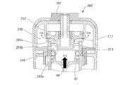
図8においてピストン47を矢印278の方向に移動させるとシリンダ室248の内部の圧力が空気圧室249の内部の圧力よりも十分大きくなるので、矢印279のように円筒窪み265bから連通路265cを介して空気圧室249側に空気が流れる。尚、Oリング273は、空気の圧力により外側から内側に押しつけられるため連通路265aを閉鎖するので、シリンダ室248の空気が外部に放出されることはない。一方、Oリング272は連通路265c側の圧力が高いため径方向外側に移動することにより矢印279の方向の空気の流れを許容する。この結果、空気圧室249内の空気量を増加させて空気圧を高めることができる。
In FIG. 8, when the piston 47 is moved in the direction of the arrow 278, the pressure inside the cylinder chamber 248 becomes sufficiently larger than the pressure inside the pneumatic chamber 249, so that the cylindrical recess 265b passes through the communication passage 265c as shown by the arrow 279. Thus, air flows to the pneumatic chamber 249 side. Since the O-ring 273 is pressed from the outside to the inside by the air pressure, the communication path 265a is closed, so that the air in the cylinder chamber 248 is not released to the outside. On the other hand, since the O-ring 272 has a high pressure on the communication path 265c side, the O-ring 272 moves outward in the radial direction, thereby allowing air flow in the direction of the arrow 279. As a result, the air pressure in the air pressure chamber 249 can be increased to increase the air pressure.
このように第1工程における空気圧室249の空気圧を上昇させる操作を、シリンダ室248においてピストン47を動かすようにして実行する。このピストン47の動力源は、ピストン47又はブレード48を動かすことができれば何を用いても良く、理論的にはブレード48を手で上下方向に移動させるか、あるいは専用の可動工具を用いることでも可能である。しかしながら、本実施例では打撃動作時にブレード48を移動させるための駆動源、ここでは電動モータ13を用いて第1工程における空気圧室249及びシリンダ室248内の加圧を行うようにした。そのため、本実施例では、電動モータ13としてマイコンにて回転位置が精度良く検出でき、正転及び逆転の制御を高精度で行うことができるブラシレスDCモータを用いるようにした。つまり、第1工程時には、電動モータ13を逆転させることにより上死点直前まで到達していたピストン47を、下死点まで下降させる、下死点に到達したら再び電動モータ13を正転させることにより上死点直前まで移動させる。この電動モータ13の逆転及び正転は、ラック53とピニオン241の噛合が外れない範囲内で行うようにし、コントローラ66に含まれるマイコンにより高精度に制御される。このようにピストン室248内でのピストン47による加圧操作(1ストローク分)を複数回繰り返すことにより、空気圧室249の空気圧を3~5気圧程度にまで加圧させることができる。空気圧室249内が所定の空気圧まで加圧されたら、マイコンにより蓄圧モードの実行が終了されるので、作業者は外気取込み弁260の切替レバー261を図6で示したもとの位置に戻す。この状態で釘11の打ち込みの事前準備(蓄圧モード)が完了したことになる。
In this manner, the operation of increasing the air pressure in the air pressure chamber 249 in the first step is executed by moving the piston 47 in the cylinder chamber 248. Any power source can be used for the piston 47 as long as the piston 47 or the blade 48 can be moved. Theoretically, the blade 48 can be moved up and down by hand, or a dedicated movable tool can be used. Is possible. However, in this embodiment, the air pressure chamber 249 and the cylinder chamber 248 are pressurized in the first step by using a drive source for moving the blade 48 during the striking operation, here, the electric motor 13. For this reason, in this embodiment, a brushless DC motor that can accurately detect the rotational position by a microcomputer and can perform forward and reverse control with high accuracy is used as the electric motor 13. That is, in the first step, the piston 47 that has reached the top dead center is lowered by reversing the electric motor 13 to the bottom dead center. When the bottom dead center is reached, the electric motor 13 is rotated forward again. To move to just before top dead center. The reverse rotation and the normal rotation of the electric motor 13 are performed within a range in which the rack 53 and the pinion 241 are not disengaged, and are controlled with high accuracy by a microcomputer included in the controller 66. Thus, by repeating the pressurizing operation (for one stroke) by the piston 47 in the piston chamber 248 a plurality of times, the air pressure in the air pressure chamber 249 can be increased to about 3 to 5 atm. When the inside of the air pressure chamber 249 is pressurized to a predetermined air pressure, the execution of the pressure accumulation mode is terminated by the microcomputer, so that the operator returns the switching lever 261 of the outside air intake valve 260 to the original position shown in FIG. In this state, preliminary preparation (accumulation mode) for driving the nail 11 is completed.
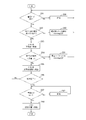
次に、電動モータ13を用いた第1工程での空気圧室249の加圧手順を図9のフローチャートを用いて説明する。図9に示す一連の手順は、コントローラ66に含まれるマイコンによって、あらかじめ格納されたプログラムを用いてソフトウェア的に実行可能である。図9のフローチャートは、図6に示す状態から切替レバー261を回転させて、図7に示すようにセレクタ265を下降させて段差部265eがシリンダ245の開口部245aに当接した状態として、蓄圧モードのスイッチ(切替レバー261)をオン(“開”)にした状態から開始される(ステップ281)。尚、図6~図8では図示されていないが、切替レバー261の位置を検出するセンサを設けて、コントローラ66により切替レバー261が切り替えられたことを検出できるように構成すると良い。
Next, the procedure for pressurizing the pneumatic chamber 249 in the first step using the electric motor 13 will be described with reference to the flowchart of FIG. A series of procedures shown in FIG. 9 can be executed by software using a program stored in advance by a microcomputer included in the controller 66. In the flowchart of FIG. 9, the switch lever 261 is rotated from the state shown in FIG. 6, the selector 265 is lowered as shown in FIG. 7, and the stepped portion 265e is in contact with the opening 245a of the cylinder 245. The mode switch (switching lever 261) is turned on ("open") and is started (step 281). Although not shown in FIGS. 6 to 8, a sensor for detecting the position of the switching lever 261 may be provided so that the controller 66 can detect that the switching lever 261 has been switched.
まず、マイコンは切替レバー261が回転されて蓄圧モードがONになったかどうかを検出する(ステップ281)。蓄圧モードになっていない場合は、作業者が蓄圧モードに切り替えるまで待機する(ステップ289)。蓄圧モードになっているときは、マイコンはマガジン16及び釘の射出路内に釘11が残っていないかを検出する(ステップ282)。この検出のためには、釘11が射出路256に装填されていないかどうか、釘11の有無を検出する公知の止具センサ等を設けると良い。マガジン16又は射出路内に釘11が残っている場合は、釘11が残っている旨のワーニングランプを点滅させ、作業者が釘11を取り出すまで待機する(ステップ290)。ここで、マガジン16及び射出路256内の釘11が無くなったら電動モータ13の回転が可能な状態になる。作業者によりトリガ72が引かれたらマイコンは電動モータ13を逆回転させて、巻き上げ用のカム(回転体238)を逆回転させることによりピストン47を下死点側へ移動させる(ステップ283)ことにより、図7の矢印276のように外気をピストン室248内に吸引する。尚、蓄圧モードにおける最初のカムの逆回転の際は、ピストン47がほとんど下死点位置にあるので、ステップ283は瞬時に終了する。
First, the microcomputer detects whether or not the pressure accumulation mode is turned on by rotating the switching lever 261 (step 281). If not in the pressure accumulation mode, the system waits until the operator switches to the pressure accumulation mode (step 289). When in the pressure accumulation mode, the microcomputer detects whether or not the nail 11 remains in the magazine 16 and the nail injection path (step 282). For this detection, it is preferable to provide a known stopper sensor or the like for detecting whether or not the nail 11 is not loaded in the injection path 256 and whether or not the nail 11 is present. If the nail 11 remains in the magazine 16 or the injection path, a warning lamp indicating that the nail 11 remains is blinked and waits until the operator removes the nail 11 (step 290). Here, when the magazine 16 and the nail 11 in the injection path 256 disappear, the electric motor 13 can be rotated. When the trigger 72 is pulled by the operator, the microcomputer reversely rotates the electric motor 13 and reversely rotates the hoisting cam (rotating body 238) to move the piston 47 to the bottom dead center side (step 283). Thus, outside air is sucked into the piston chamber 248 as indicated by an arrow 276 in FIG. In the reverse rotation of the first cam in the pressure accumulation mode, since the piston 47 is almost at the bottom dead center position, step 283 is instantaneously ended.
次に、マイコンはカム(回転体238)の逆回転の時のモータに流れる電流値Iを検出することによって、射出路内に釘11が詰まっている状態、つまり釘詰まり状態であるかを検出する。これは検出された電流値Iが、釘詰まりを示す電流の閾値I0を越えているか否かで判定できる(ステップ284)。電流値Iは、電動モータ13を駆動させるための制御回路に含まれる電流検出回路を通じてマイコンが常時監視しているので、その検出値を利用すれば、新たな電流検出手段を設ける必要は無い。ここでは、ピストン47を下降させるときに、電動モータ13にてスムーズに下降させることができれば、モータに流れる電流値Iがさほど大きくならないからである。この電流値Iが設定された電流値(閾値I0)を越えた場合は、ピストン47及びブレード48の移動を阻害する原因があるため、釘11が残っている旨のワーニングランプを点滅させ、作業者が釘11を取り出すまで待機する(ステップ291)。
Next, the microcomputer detects the current value I flowing to the motor when the cam (rotating body 238) rotates in reverse, thereby detecting whether the nail 11 is clogged in the injection path, that is, whether the nail is clogged. To do. This can be determined by whether or not the detected current value I exceeds a current threshold value I 0 indicating nail clogging (step 284). Since the microcomputer constantly monitors the current value I through a current detection circuit included in the control circuit for driving the electric motor 13, if the detected value is used, it is not necessary to provide a new current detection means. Here, when the piston 47 is lowered, if the electric motor 13 can be lowered smoothly, the current value I flowing through the motor does not increase so much. When this current value I exceeds the set current value (threshold value I 0 ), there is a cause of obstructing the movement of the piston 47 and the blade 48, so the warning lamp that the nail 11 remains is blinked, Wait until the operator removes the nail 11 (step 291).
次に、マイコンは電動モータ13を正回転(打撃時にピストン47を巻き上げる方向の回転であって、図2の矢印で示す方向への回転)させて、巻き上げ用のカム(回転体238)を正回転させることによりピストン47を下死点から上死点の近傍(手前)まで移動させる(ステップ285)。この移動によって図8で示した矢印249のようにシリンダ室248の空気(外部より吸引した空気)を空気圧室249内に送出することができる。ここでピストン47を上死点まで移動させると、巻き上げ用のカム(回転体238)とブレード48のラック53の係合状態が外れて、ピストン47が蓄圧された空気の圧力で急激に移動してしまう(打撃モードと同じ)ので、上死点の直前位置でピストン47の上昇を停止させることが重要である。このようにピストン47の下降動作(ステップ283)及び上昇動作(ステップ285)によって図7及び図8で示したように、外気取込み弁260を介して外気を吸引して、空気圧室249の空気を増量させて、空気圧を高めることができる。
Next, the microcomputer rotates the electric motor 13 in the forward direction (rotation in the direction in which the piston 47 is wound up when hitting, in the direction indicated by the arrow in FIG. 2), and the cam for rotation (rotating body 238) is moved forward. By rotating, the piston 47 is moved from the bottom dead center to the vicinity of the top dead center (front) (step 285). By this movement, the air in the cylinder chamber 248 (air sucked from the outside) can be sent into the pneumatic chamber 249 as indicated by an arrow 249 shown in FIG. Here, when the piston 47 is moved to the top dead center, the engagement state between the hoisting cam (rotating body 238) and the rack 53 of the blade 48 is disengaged, and the piston 47 moves rapidly with the pressure of the accumulated air. Therefore, it is important to stop the lift of the piston 47 at a position immediately before the top dead center. Thus, as shown in FIGS. 7 and 8 by the lowering operation (step 283) and the raising operation (step 285) of the piston 47, the outside air is sucked through the outside air intake valve 260, and the air in the air pressure chamber 249 is drawn. The air pressure can be increased by increasing the air pressure. *
次に、マイコンはピストン47の下降及び上昇操作により行う蓄圧が完了したか否かを判定する(ステップ286)。この蓄圧(加圧動作)が完了したかどうかは、例えば下記のいずれかの方法により実施できる。(1)ピストン47を下死点側から上死点側へ移動させるときの、電動モータ13に流れる電流値Iを検出して、それが蓄圧動作完了時の閾値I1よりも大きくなったかどうかを判定する。空気圧室249内の圧力(ここでは蓄圧モードにより3~5気圧程度まで加圧することを想定)が上昇すると、ピストン47を下死点側から上死点側へ移動させるときの負荷が大きくなるため、負荷の上昇に伴い電流値Iが増加するためである。(2)空気圧室249内の圧力を測定する図示しない圧力センサを設けて、その圧力Pが設定圧力P0を越えたか否かを検出する。この方法は、空気圧を直接測定するので、一番精度が良い方法である。しかしながら圧力センサを設ける必要があるので、コストの上昇、装置の大型化につながることになる。(3)ピストン47を上死点直前位置から下死点まで戻し、再び下死点から上死点直前位置まで上昇させるという1ストローク分の動作を何回実行したかをマイコンがカウントする。このピストンの往復移動させた回数が、所定回数たる閾値N回分実行されたら蓄圧動作を終了させる。この閾値は例えば3回とすることができる。 以上のいずれかの方法により蓄圧動作が完了したと判断したら(ステップ286)、マイコンは切替レバー261が回転されて蓄圧モードがOFFになったかどうかを検出する(ステップ287)。蓄圧モードのままの場合は、作業者が切替レバー261を操作して蓄圧モードをOFFにするまで待機する(ステップ292)。蓄圧モードがOFFになったとき、つまり切替レバー261が図6の状態に戻されたとき、マイコンはピストン47を初期位置(下死点又は下死点近くの所定位置)に戻して(ステップ288)、第1工程による空気圧室249の蓄圧処理を終了させる。この後、作業者は実際の釘打ち動作(第2工程)を実行することができる。
Next, the microcomputer determines whether or not pressure accumulation performed by the lowering and raising operations of the piston 47 is completed (step 286). Whether or not this pressure accumulation (pressurizing operation) is completed can be carried out, for example, by any of the following methods. (1) Whether or not the current value I flowing through the electric motor 13 when the piston 47 is moved from the bottom dead center side to the top dead center side is detected, and whether or not it has become larger than the threshold value I 1 when the pressure accumulation operation is completed Determine. If the pressure in the pneumatic chamber 249 (here, it is assumed that the pressure is increased to about 3 to 5 atm in the pressure accumulation mode) increases, the load when moving the piston 47 from the bottom dead center to the top dead center increases. This is because the current value I increases as the load increases. (2) provided with a pressure sensor (not shown) for measuring the pressure in the air pressure chamber 249, detects whether the pressure P exceeds the set pressure P 0. This method is the most accurate method because it directly measures the air pressure. However, it is necessary to provide a pressure sensor, which leads to an increase in cost and an increase in the size of the apparatus. (3) The microcomputer counts how many times the operation for one stroke of returning the piston 47 from the position just before the top dead center to the bottom dead center and raising the piston 47 from the position just before the top dead center to the position just before the top dead center is executed. When the number of times the piston has been reciprocated is executed for a predetermined number of times N, the pressure accumulation operation is terminated. This threshold can be set to 3 times, for example. When it is determined that the pressure accumulation operation has been completed by any of the above methods (step 286), the microcomputer detects whether or not the pressure accumulation mode is turned off by rotating the switching lever 261 (step 287). If the pressure accumulation mode remains, the operator waits until the operator operates the switching lever 261 to turn off the pressure accumulation mode (step 292). When the pressure accumulation mode is turned off, that is, when the switching lever 261 is returned to the state shown in FIG. 6, the microcomputer returns the piston 47 to the initial position (bottom dead center or a predetermined position near the bottom dead center) (step 288). ), The pressure accumulation process of the pneumatic chamber 249 in the first step is terminated. Thereafter, the operator can execute an actual nail driving operation (second step).
以上、第一の実施例によれば、電動モータ13により駆動させるピストン47の動きによって空気圧室249内の気体の圧力を高めることができるので、長年の使用による空気圧室内の圧力低下に悩まされることなく、長寿命かつ高性能の打込機を実現できる。
As described above, according to the first embodiment, the pressure of the gas in the pneumatic chamber 249 can be increased by the movement of the piston 47 driven by the electric motor 13, so that the pressure drop in the pneumatic chamber due to many years of use is plagued. Long life and high performance driving machine can be realized.
次に図10及び図11を用いて本発明の第二の実施例を説明する。第二の実施例の打込機301において第一の実施例と異なる点は、空気圧室349の圧力が所定値を越えた場合に、内部の空気を外部に逃がすための手動リーク機構、即ちリークバルブ360を蓄圧容器350に設けたことにある。このため蓄圧容器350の形状を径方向に伸ばして、上面の外気取込み弁260の隣接する位置にリークバルブ360を設けた。外気取込み弁260の構造や機能は、第一の実施例で説明したものと同じである。蓄圧容器350は、第一の実施例と同様に、容器本体部351とフランジ部355にて二分割型式で製造されるが、圧縮空気を貯蔵する容器としては一体式でも分割式でも良く、また、その他の構造でも良い。蓄圧容器350の形状変更に伴い、打込機301の本体ハウジング302の上部部分の形状が変更されているが、蓄圧容器350近傍の形状を除くと、その他の部分は第一の実施例の打込機201と同じ構造である。
Next, a second embodiment of the present invention will be described with reference to FIGS. The driving machine 301 of the second embodiment is different from the first embodiment in that a manual leak mechanism for releasing the internal air to the outside when the pressure in the pneumatic chamber 349 exceeds a predetermined value, that is, a leak The valve 360 is provided in the pressure accumulation container 350. Therefore, the shape of the pressure accumulating vessel 350 is extended in the radial direction, and the leak valve 360 is provided at a position adjacent to the outside air intake valve 260 on the upper surface. The structure and function of the outside air intake valve 260 are the same as those described in the first embodiment. As in the first embodiment, the pressure accumulating vessel 350 is manufactured in a two-split type with a container main body portion 351 and a flange portion 355, but the container for storing compressed air may be an integral type or a divided type. Other structures may be used. The shape of the upper portion of the main body housing 302 of the driving machine 301 has been changed along with the change in the shape of the pressure accumulating vessel 350. Except for the shape near the pressure accumulating vessel 350, the other portions are the same as those in the first embodiment. The structure is the same as the embedded machine 201.
図11はリークバルブ360の詳細構造を示す縦断面図である。リークバルブ360は空気圧室349(図10参照)の圧力が所定値を越えた場合に内部の空気を外部に逃がすという“リリースバルブ”としての機能に加えて、作業者が任意のタイミングで空気圧室349の空気を排出できるという“リークバルブ”としての機能を設けた。リークバルブによる任意排気機能は、ノーズ部254に形成された射出路256(図2参照)に釘11が詰まった際に、詰まった釘11の取り除く作業を行うときに用いると便利である。これは空気圧室349の圧力が高い状態のまま釘11を取り除こうとしても、ブレード48を動かすことが困難になることがあるためである。一方、釘11の取り除き作業の際に空気圧室349の空気を抜くようにすれば、空気圧室349とシリンダ室248の内部が大気圧となるため、作業者が容易にブレード48を動かすことができる。さらに、空気圧室349を大気圧に戻せば、ピストン47を移動させる力が無くなるので、誤って打撃動作が行われる恐れがなくなるので、安全性が一層向上する。
FIG. 11 is a longitudinal sectional view showing the detailed structure of the leak valve 360. The leak valve 360 has a function as a “release valve” that releases internal air to the outside when the pressure in the pneumatic chamber 349 (see FIG. 10) exceeds a predetermined value. A function as a “leak valve” capable of discharging 349 air was provided. The optional exhaust function using the leak valve is convenient when removing the clogged nail 11 when the nail 11 is clogged in the injection path 256 (see FIG. 2) formed in the nose portion 254. This is because it may be difficult to move the blade 48 even if the nail 11 is removed while the pressure in the pneumatic chamber 349 is high. On the other hand, if the air in the pneumatic chamber 349 is removed when the nail 11 is removed, the inside of the pneumatic chamber 349 and the cylinder chamber 248 becomes atmospheric pressure, so that the operator can easily move the blade 48. . Furthermore, if the air pressure chamber 349 is returned to the atmospheric pressure, the force for moving the piston 47 is lost, so there is no possibility that the striking operation is erroneously performed, and the safety is further improved.
図11(1)(2)において、蓄圧容器350の容器本体部351に空気圧室349内の空気の出口となる貫通穴353を形成し、所定の状態の時に貫通穴353からの空気の排出を許可するリークバルブ360を設けた。リークバルブ360は、容器本体部351を内側にカップ状に突出させた太径部351c及び細径部351dと、太径部351c及び細径部351dの内部で軸方向に移動可能な円筒状のプランジャ370と、プランジャ370を容器本体部351に保持するためのプランジャホルダ361と、プランジャ370を移動させるためのプッシュボタン385と、円筒状のプランジャ370の内部に配置されたボール381と、ボール381を所定の方向に付勢するためのプッシャ382を含んで構成される。
11 (1) and 11 (2), a through hole 353 serving as an air outlet in the pneumatic chamber 349 is formed in the container main body 351 of the pressure accumulating container 350, and air is discharged from the through hole 353 in a predetermined state. An allowed leak valve 360 was provided. The leak valve 360 includes a cylindrical portion that can move in the axial direction inside the large diameter portion 351c and the small diameter portion 351d, and a large diameter portion 351c and a small diameter portion 351d that project the container main body portion 351 in a cup shape. Plunger 370, plunger holder 361 for holding plunger 370 in container body 351, push button 385 for moving plunger 370, ball 381 disposed inside cylindrical plunger 370, ball 381 And a pusher 382 for biasing in a predetermined direction.
プランジャ370には複数の通路(連通路371、374)と、ボール381にて弁機構を果たすための絞り部分372が形成され、外周面にはプランジャホルダ361との間の密閉を保つためのゴム製のOリング376~378が設けられる。ボール381は容器本体部351の外側からプランジャ370の内部に挿入され、プッシャ382とコイルバネ383により付勢され、金属プレート384によって保持される。金属プレート384は合成樹脂製のプッシュボタン385により抜け止めされる。尚、プッシュボタン385の下側には止め輪386が挿入される。プランジャホルダ361はプランジャ370を容器本体部351に保持すると共に、プランジャ370の外周側の溝部と共に所定の空気通路を形成したり、又は、閉鎖したりするものである。プランジャホルダ361は、本体ハウジング302の貫通穴302cを貫通させて、容器本体部351の太径部351cに圧入されるものであって、それらの間の気密性を保つためにOリング363が設けられる。また、容器本体部351を軸方向に対して直交方向に延びる排出管路365が設けられる。排出管路365は容器本体部351の一部にドリル等で形成され、本体外とプランジャホルダ361に形成された横穴361cとを連通している。
Plunger 370 is formed with a plurality of passages (communication passages 371 and 374) and a throttle portion 372 for performing a valve mechanism with ball 381, and rubber for maintaining a tight seal with plunger holder 361 on the outer peripheral surface. Made O-rings 376-378 are provided. The ball 381 is inserted into the plunger 370 from the outside of the container body 351, is urged by the pusher 382 and the coil spring 383, and is held by the metal plate 384. The metal plate 384 is prevented from coming off by a push button 385 made of synthetic resin. A retaining ring 386 is inserted below the push button 385. The plunger holder 361 holds the plunger 370 on the container main body 351 and forms a predetermined air passage with the groove on the outer peripheral side of the plunger 370 or closes it. The plunger holder 361 passes through the through hole 302c of the main body housing 302 and is press-fitted into the large diameter portion 351c of the container main body portion 351. An O-ring 363 is provided to maintain airtightness between them. It is done. In addition, a discharge pipe line 365 extending in a direction orthogonal to the axial direction of the container main body 351 is provided. The discharge pipe 365 is formed in a part of the container main body 351 by a drill or the like, and communicates the outside of the main body with the lateral hole 361 c formed in the plunger holder 361.
図11(1)は、打込機301の未使用時、又は、通常の打撃動作が行われている際の状態である。(2)は作業者によって矢印395の方向にプッシュボタン385が押し下げられた状態を示すもので、プッシュボタン385が軸方向下側に移動することで、矢印391に示すように、貫通穴353から排出管路365への空気通路が画定される。ここでは貫通穴353からプランジャホルダ361の下端部と太径部351cの内側の隙間を通って、プランジャホルダ361の内周側の斜面部とOリング377との間に生まれた隙間を通って上方に流れ、軸方向下側から連通するように円周方向に連続する幅広溝375部分に空気が流れて、排出管路365から矢印391のように外部に空気が排出される。この空気の排出時には高圧空気の排出音がするが、この音が止まったら作業者はプッシュボタン385の押し下げを解除すると、プランジャ370はコイルバネ379の復元力によって(1)の状態に戻る。このように、プッシュボタン385を押下することによる蓄圧容器350の減圧は、釘詰まりが起きた場合であって、詰まった釘を取り除く際に操作することができる。
FIG. 11 (1) shows a state when the driving machine 301 is not used or when a normal hitting operation is performed. (2) shows a state in which the push button 385 is pushed down in the direction of the arrow 395 by the operator. When the push button 385 moves downward in the axial direction, as shown by the arrow 391, the push button 385 is removed from the through hole 353. An air passage to the exhaust line 365 is defined. Here, the through hole 353 passes through the gap between the lower end portion of the plunger holder 361 and the inside of the large diameter portion 351c, and passes through the gap created between the inclined surface portion on the inner peripheral side of the plunger holder 361 and the O-ring 377. The air flows through the wide groove 375 continuous in the circumferential direction so as to communicate from the lower side in the axial direction, and the air is discharged to the outside from the discharge pipe 365 as indicated by an arrow 391. When this air is discharged, a high-pressure air discharge sound is generated. When this sound stops, when the operator releases the push button 385, the plunger 370 returns to the state (1) by the restoring force of the coil spring 379. Thus, the pressure reduction of the pressure accumulating vessel 350 by pressing the push button 385 is a case where a nail is clogged and can be operated when removing the clogged nail.
図11(3)は、打込機301の空気圧室349の加圧を行って規定の量以上の空気を入れてしまった際に、リリースバルブとして作用する際の状況を示す図である。本実施例の打込機301は、長さが50~90mm程度の釘の打ち込みを想定しており、蓄圧しておく前準備工程(第1工程)では空気圧室内を5~8気圧程度とし、実際の打ち込みを行う打撃工程(第2工程)では、空気圧室内は最大10~14気圧程度にまで増加する。仮に、第1工程における蓄圧が規定量以上に行われた後に、打撃工程を行うと、空気圧室349の圧力が所定値を越えてしまうことになる。その際には(3)に示す矢印393の経路によって過剰な空気が外部に排出される。(3)の状態ではプッシュボタン385は(1)と同じ通常位置にあるため、(2)で示した排出経路を取ることができない。そこでボール381で閉鎖される絞り部分372とプランジャホルダ361の下端部と太径部351cの内側の隙間との間を空間的に接続する連通路371を設けて、空気圧室349の圧力(矢印392)がボール381にかかるようにした。よってボール381に所定以上の空気圧が掛かるとプッシャ382を介してコイルバネ383を圧縮させることにより、ボール381が絞り部分372から離脱する。するとボール381の周囲を流れて、連通路374を通って矢印393のように過剰な空気が外部に排出される。尚、(3)では矢印393は左向きに排出するように図示しているが、右向きにも同様に排出される。この際、所定量の空気が排出されて空気圧室349の圧力が適正空気圧になるとコイルバネ383のバネ力が空気圧室349の圧力(矢印392)よりも強くなり、ボール381が再び絞り部分372に押しつけられることにより、図11(1)の状態に戻り、空気圧室349内の密閉状態が保たれる。
FIG. 11 (3) is a diagram showing a situation when acting as a release valve when the air pressure chamber 349 of the driving machine 301 is pressurized and air of a predetermined amount or more is introduced. The driving machine 301 of this embodiment assumes driving of a nail having a length of about 50 to 90 mm. In the preparatory step (first step) for accumulating pressure, the pneumatic chamber is set to about 5 to 8 atm. In the striking process (second process) in which actual driving is performed, the air pressure chamber increases to a maximum of about 10 to 14 atm. If the striking process is performed after the accumulated pressure in the first process is over a specified amount, the pressure in the pneumatic chamber 349 will exceed a predetermined value. At that time, excess air is discharged to the outside through a path indicated by an arrow 393 shown in (3). In the state of (3), since the push button 385 is in the same normal position as (1), the discharge path shown in (2) cannot be taken. Therefore, a communication passage 371 that spatially connects the throttle portion 372 closed by the ball 381, the lower end of the plunger holder 361, and the gap inside the large diameter portion 351c is provided, and the pressure (arrow 392) of the pneumatic chamber 349 is provided. ) On the ball 381. Therefore, when a predetermined or higher air pressure is applied to the ball 381, the coil spring 383 is compressed via the pusher 382, so that the ball 381 is detached from the throttle portion 372. Then, the air flows around the ball 381, and excess air is discharged to the outside through the communication path 374 as indicated by an arrow 393. In addition, in (3), the arrow 393 is illustrated so as to be discharged leftward, but the same is discharged to the right. At this time, when a predetermined amount of air is discharged and the pressure in the air pressure chamber 349 becomes an appropriate air pressure, the spring force of the coil spring 383 becomes stronger than the pressure in the air pressure chamber 349 (arrow 392), and the ball 381 is again pressed against the throttle portion 372. As a result, the state of FIG. 11 (1) is restored and the sealed state in the pneumatic chamber 349 is maintained.
以上、第二の実施例によれば釘詰まりが起きて釘の取り出しを行うとき、作業者が空気圧室349の高圧空気を開放することができるので、安全な状態で釘の取り出し作業を行うことができる。また、長期間にわたり打込機を使用しない場合など、作業者の希望により空気圧室349の高圧空気を開放できるので、空気圧室のシール部分や、ピストンのシール部等が早期に経年劣化することを防止できる。さらに、空気圧室349の内部が規定値以上に高圧になったときは、内部の過剰な空気を自動的に排出させることができるので、第1工程での加圧作業を失敗する恐れがない。
As described above, according to the second embodiment, when the nail is clogged and the nail is taken out, the operator can release the high-pressure air in the pneumatic chamber 349, so that the nail is taken out in a safe state. Can do. In addition, when the driving machine is not used for a long period of time, the high pressure air in the pneumatic chamber 349 can be released at the operator's request, so that the seal portion of the pneumatic chamber, the seal portion of the piston, etc. may deteriorate quickly over time. Can be prevented. Furthermore, when the pressure inside the pneumatic chamber 349 becomes higher than a specified value, excess air inside can be automatically discharged, so that the pressurizing operation in the first step does not fail.
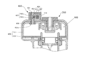
図12は第二の実施例の変形例であり、図11のリークバルブ360を電磁バルブ460に置き換えたものである。電磁バルブ460は容器本体部451に貫通するように配置され、排出される空気の連通路462を形成する排出管461と、連通路462を開放又は遮断するための弁463と、弁463を移動させるソレノイドアクチュエータ464を設けた。排出管461は軸方向中央が閉鎖された略円筒状の部材であり、容器本体部451の貫通穴部451bに装着され、ゴム製のOリング468を介在させたうえで取り付けられる。排出管461の閉鎖部分には、軸方向及び径方向に延びる極細の連通路462a、462bが形成される。連通路462a、462bの径方向に延びる部分は、排出管461の外周側に形成された窪み部分に露出し、その窪み部分を覆うように弁463が配置される。ソレノイドアクチュエータ464は、ハウジング465内に設けられたコイル466の内側において磁力で鉄芯467を移動させる。鉄芯467には弁463が固定され、コイル466に通電することにより弁463が連通路462側に接近するように移動し、コイル466への通電を停止することにより図示しないスプリングの作用により弁463が連通路462から離れる側に移動する。この弁463の連通路462からの離反によって、排出管461の窪み部分と弁463の間に空間が形成されて通路462aと462bが連通されるため、空気圧室449の加圧された空気を排出管461を介して外部に排出させることができる。このようにマイコンの制御によってソレノイドアクチュエータ464を駆動することにより連通路462の開放または遮断の制御が可能になる。
FIG. 12 shows a modification of the second embodiment, in which the leak valve 360 in FIG. 11 is replaced with an electromagnetic valve 460. The electromagnetic valve 460 is disposed so as to penetrate the container main body 451 and moves the discharge pipe 461 that forms the communication path 462 of the discharged air, the valve 463 for opening or closing the communication path 462, and the valve 463. A solenoid actuator 464 is provided. The discharge pipe 461 is a substantially cylindrical member whose center in the axial direction is closed. The discharge pipe 461 is attached to the through hole 451b of the container body 451, and is attached with a rubber O-ring 468 interposed therebetween. In the closed portion of the discharge pipe 461, extremely thin communication passages 462a and 462b extending in the axial direction and the radial direction are formed. Portions extending in the radial direction of the communication passages 462a and 462b are exposed to a recessed portion formed on the outer peripheral side of the discharge pipe 461, and a valve 463 is disposed so as to cover the recessed portion. The solenoid actuator 464 moves the iron core 467 by a magnetic force inside a coil 466 provided in the housing 465. A valve 463 is fixed to the iron core 467, and when the coil 466 is energized, the valve 463 moves so as to approach the communication path 462 side, and when the coil 466 is de-energized, the valve 463 is operated by the action of a spring (not shown). 463 moves to the side away from the communication path 462. By separating the valve 463 from the communication passage 462, a space is formed between the recessed portion of the discharge pipe 461 and the valve 463 so that the passages 462a and 462b communicate with each other, so that the pressurized air in the pneumatic chamber 449 is discharged. It can be discharged to the outside through the tube 461. In this way, by driving the solenoid actuator 464 under the control of the microcomputer, the communication path 462 can be opened or shut off.
以上、第二の実施例の変形例によれば、釘詰まり等の異常が起きて、マイコンが釘の取り出しが必要であると検出したときに、マイコンが電磁バルブ460を操作することにより空気圧室449の高圧空気を開放することができるので、作業者は安全な状態で釘の取り出し作業を行うことができる。また、釘の取り出しが完了した後には、作業者が外気取込み弁260を操作して、第1工程における空気圧室449の圧力を上昇させる蓄圧モードを実行できるので、使い勝手の良い打込機を実現できる。
As described above, according to the modification of the second embodiment, when an abnormality such as a nail clogging occurs and the microcomputer detects that the nail needs to be removed, the microcomputer operates the electromagnetic valve 460 to operate the pneumatic chamber. Since the high-pressure air of 449 can be released, the operator can take out the nail in a safe state. In addition, after the nail removal is completed, the operator can operate the outside air intake valve 260 to execute the pressure accumulation mode in which the pressure in the air pressure chamber 449 in the first step is increased. it can.
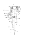
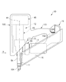
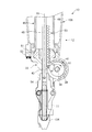
次に図13~図16を用いて本発明の第三の実施例を説明する。図13の基本構成、特にマガジン16等の釘送り機構、電動モータ13による駆動、グリップ101や装着部1の形状、蓄電池15を動力源とする点、蓄電池15が装着部102に対して着脱可能である点等は第一の実施例で説明した打込機201とほぼ同じである。異なる主な点は釘11を打撃する打撃機構12であり、空気圧室を加圧するための機構が異なる。ここでは第一の実施例のようにピストン47を利用して蓄圧を行うのではなく、空気圧室を可動式の第二のシリンダ46にて構成して、シリンダ46を電動モータ13(後述)の駆動力によって上下方向に移動可能とした。また、シリンダ46の形態に合わせてカバー100の形状も異なる。図示しない電動モータ13はモータハウジング17内に設けられており、その構造は図1で説明したものと同型式のブラシレスDCモータである。モータハウジング17に隣接するケーシング33の内部には図1で説明したものと同型式の減速機27が収容され、ケーシング33は筒状のノーズ部54に接続される。
Next, a third embodiment of the present invention will be described with reference to FIGS. The basic configuration of FIG. 13, in particular, a nail feed mechanism such as a magazine 16, driving by the electric motor 13, the shape of the grip 101 and the mounting portion 1, the point that uses the storage battery 15 as a power source, These are substantially the same as the driving machine 201 described in the first embodiment. A different main point is a striking mechanism 12 for striking the nail 11, and a mechanism for pressurizing the pneumatic chamber is different. Here, pressure accumulation is not performed using the piston 47 as in the first embodiment, but the pneumatic chamber is configured by a movable second cylinder 46, and the cylinder 46 is connected to the electric motor 13 (described later). It can be moved up and down by the driving force. Further, the shape of the cover 100 is different depending on the form of the cylinder 46. The electric motor 13 (not shown) is provided in the motor housing 17, and the structure thereof is a brushless DC motor of the same type as that described in FIG. A reduction gear 27 of the same type as that described in FIG. 1 is accommodated in the casing 33 adjacent to the motor housing 17, and the casing 33 is connected to a cylindrical nose portion 54.
図14は図13のA方向から見た側面図であり、一部を断面図にして示す。電動モータ13の回転駆動力は減速機27の出力を介して、駆動軸34と従動軸35に伝達される。ここでは従動軸35の回転によって駆動される第1動力伝達経路と、駆動軸34の回転によって駆動される第2動力伝達経路の2つの動力伝達経路が設けられる。第1動力伝達経路は、従動軸35によって回転されるギヤ44を用いて可動式の第二のシリンダ46の上下方向に移動可能とするものである。第2動力伝達経路は、駆動軸34によって回転されるギヤ41を用いて、ブレード48を上方向に移動させることによりピストン47(図15参照)を下死点から上死点まで移動させる。詳細は後述するが電動モータ13を正方向に回転させると駆動軸34にだけ動力が伝達されギヤ41だけが回転し、反対方向に回転させると従動軸35にだけ動力が伝達されギヤ44だけが回転するように構成される。従って電動モータ13の回転方向を設定することによって、第1動力伝達経路側に動力を伝達するか、第2動力伝達経路側に動力を伝達するかを択一的に選択できる。
FIG. 14 is a side view as seen from the direction A in FIG. The rotational driving force of the electric motor 13 is transmitted to the drive shaft 34 and the driven shaft 35 via the output of the speed reducer 27. Here, two power transmission paths are provided: a first power transmission path driven by the rotation of the driven shaft 35 and a second power transmission path driven by the rotation of the drive shaft 34. The first power transmission path is movable in the vertical direction of the movable second cylinder 46 using the gear 44 rotated by the driven shaft 35. The second power transmission path moves the piston 47 (see FIG. 15) from the bottom dead center to the top dead center by moving the blade 48 upward using the gear 41 rotated by the drive shaft 34. Although details will be described later, when the electric motor 13 is rotated in the forward direction, power is transmitted only to the drive shaft 34 and only the gear 41 is rotated, and when rotated in the opposite direction, power is transmitted only to the driven shaft 35 and only the gear 44 is transmitted. Configured to rotate. Therefore, by setting the rotation direction of the electric motor 13, it is possible to alternatively select whether to transmit power to the first power transmission path side or to transmit power to the second power transmission path side.
駆動軸34は電動モータ13の出力軸24(図1参照)と同心に配置され、軸線A1を中心として回転可能である。駆動軸34には回転体37及び回転体38が取り付けられている。回転体37の外周面にギヤ40が設けられ、ギヤ40によって回転力は従動軸35側に伝達される。回転体37の外周面にギヤ40が設けられている。回転体37と駆動軸34との動力伝達経路を接続または遮断するワンウェイクラッチ39(図15参照)が設けられ、駆動軸34が図14で反時計方向に回転すると、駆動軸34の回転力を回転体37に伝達する。ワンウェイクラッチ39は、駆動軸34が図14で時計方向に回転しても、駆動軸34の回転力を回転体37に伝達しない。つまり、ワンウェイクラッチ39は、駆動軸34の回転方向に応じて、駆動軸34と従動軸35との間の動力伝達経路を接続または遮断する。
The drive shaft 34 is disposed concentrically with the output shaft 24 (see FIG. 1) of the electric motor 13 and is rotatable about the axis A1. A rotating body 37 and a rotating body 38 are attached to the drive shaft 34. A gear 40 is provided on the outer peripheral surface of the rotating body 37, and the rotational force is transmitted to the driven shaft 35 side by the gear 40. A gear 40 is provided on the outer peripheral surface of the rotating body 37. A one-way clutch 39 (see FIG. 15) for connecting or disconnecting the power transmission path between the rotator 37 and the drive shaft 34 is provided, and when the drive shaft 34 rotates counterclockwise in FIG. This is transmitted to the rotating body 37. The one-way clutch 39 does not transmit the rotational force of the drive shaft 34 to the rotating body 37 even if the drive shaft 34 rotates clockwise in FIG. That is, the one-way clutch 39 connects or disconnects the power transmission path between the drive shaft 34 and the driven shaft 35 according to the rotation direction of the drive shaft 34.
回転体38の外周面に、所定角度の範囲内でギヤ41が設けられている。また、回転体38の回転方向において、ギヤ41が設けられていない箇所にローラ42が設けられている。ローラ42の外周面の一部は、回転体38の外周面よりも外側に配置されている。ローラ42は回転可能に支持されている。
A gear 41 is provided on the outer peripheral surface of the rotating body 38 within a predetermined angle range. A roller 42 is provided at a location where the gear 41 is not provided in the rotational direction of the rotating body 38. A part of the outer peripheral surface of the roller 42 is disposed outside the outer peripheral surface of the rotating body 38. The roller 42 is rotatably supported.
従動軸35にギヤ44が設けられている。ギヤ44は、ギヤ40と噛み合っている。ブレード48は、中心線B1に沿って配置され、かつ、軸孔52(図15参照)内で移動可能である。ケーシング33に回転体60の回転を規制する保持部材たる回り止め73が設けられている。回り止め73は、支持軸74を中心として揺動可能である。回り止め73は、ギヤ61に噛み合うことで、回転体60が図14で反時計方向に回転することを防止し、時計方向に回転することを許容する。つまり、ギヤ61と回り止め73とで、ラチェット機構を構成している。ブレード48には、長さ方向にラック53が設けられている。ギヤ41は、ラック53に噛み合うこと、またはラック53から離脱することが可能である。ケーシング33は、筒状のノーズ部54を有し、ブレード48はノーズ部54内で移動可能である。
A gear 44 is provided on the driven shaft 35. The gear 44 meshes with the gear 40. The blade 48 is disposed along the center line B1 and is movable in the shaft hole 52 (see FIG. 15). The casing 33 is provided with a rotation stopper 73 that is a holding member that restricts the rotation of the rotating body 60. The rotation stopper 73 can swing around the support shaft 74. The rotation stopper 73 meshes with the gear 61 to prevent the rotating body 60 from rotating counterclockwise in FIG. 14 and to allow it to rotate clockwise. In other words, the gear 61 and the rotation stopper 73 constitute a ratchet mechanism. The blade 48 is provided with a rack 53 in the length direction. The gear 41 can be engaged with the rack 53 or can be detached from the rack 53. The casing 33 has a cylindrical nose portion 54, and the blade 48 is movable in the nose portion 54.
ノーズ部54は、カバー100(図13参照)の外に露出している。ノーズ部54にプッシュロッド104が設けられている。プッシュロッド104は、ノーズ部54に対して中心線B1に沿った方向に所定の範囲で移動可能である。プッシュロッド104は圧縮バネ105(図15参照)の力で中心線B1に沿った方向に押されて停止している。プッシュロッド104を物体に押し付けると、プッシュロッド104は圧縮バネ105(図15参照)の力に抗して中心線B1方向に移動して停止する。
The nose portion 54 is exposed outside the cover 100 (see FIG. 13). A push rod 104 is provided on the nose portion 54. The push rod 104 is movable within a predetermined range in the direction along the center line B1 with respect to the nose portion 54. The push rod 104 is stopped by being pushed in the direction along the center line B1 by the force of the compression spring 105 (see FIG. 15). When the push rod 104 is pressed against the object, the push rod 104 moves in the direction of the center line B1 against the force of the compression spring 105 (see FIG. 15) and stops.
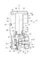
図15は、図13に示す打込機の正面断面図である。打撃機構12は、図15に示すように、第一のシリンダ45、第二のシリンダ46、ピストン47、ブレード48を備えている。シリンダ45及びシリンダ46は、カバー100(図13参照)内に配置されている。シリンダ45は、円筒部49と、円筒部49に連続する外向きのフランジ50と、を備えている。円筒部49の中心線B1は、軸線A1と略直角に交差しており、円筒部49の中心線B1に沿った方向の第1端部(下端部)がケーシング33に固定されている。動力伝達機構14の一部はケーシング33内に設けられている。動力伝達機構14は、互いに平行に配置された駆動軸34及び従動軸35を備えている。駆動軸34は、軸受36を介してケーシング33により回転可能に支持されている。駆動軸34は出力軸24と同心状に配置され、かつ、軸線D1を中心として回転可能である。また、駆動軸34に回転体37及び回転体38が取り付けられている。回転体37は、軸線A1に沿った方向で、回転体38と減速機27との間に配置されている。駆動軸34の回転方向は、電動モータ13のロータ19の回転方向と同じである。回転体38と駆動軸34の間にはワンウェイクラッチ43が設けられる。ワンウェイクラッチ43は、駆動軸34が図14で時計方向に回転すると駆動軸34の回転力を回転体38に伝達し、反時計方向に回転した場合は駆動軸34の回転力を回転体38に伝達しない。
15 is a front sectional view of the driving machine shown in FIG. As shown in FIG. 15, the striking mechanism 12 includes a first cylinder 45, a second cylinder 46, a piston 47, and a blade 48. The cylinder 45 and the cylinder 46 are disposed in the cover 100 (see FIG. 13). The cylinder 45 includes a cylindrical portion 49 and an outward flange 50 that is continuous with the cylindrical portion 49. A center line B <b> 1 of the cylindrical portion 49 intersects the axis A <b> 1 at a substantially right angle, and a first end (lower end) in a direction along the center line B <b> 1 of the cylindrical portion 49 is fixed to the casing 33. A part of the power transmission mechanism 14 is provided in the casing 33. The power transmission mechanism 14 includes a drive shaft 34 and a driven shaft 35 that are arranged in parallel to each other. The drive shaft 34 is rotatably supported by the casing 33 via a bearing 36. The drive shaft 34 is disposed concentrically with the output shaft 24 and is rotatable about the axis D1. A rotating body 37 and a rotating body 38 are attached to the drive shaft 34. The rotating body 37 is disposed between the rotating body 38 and the speed reducer 27 in the direction along the axis A1. The rotation direction of the drive shaft 34 is the same as the rotation direction of the rotor 19 of the electric motor 13. A one-way clutch 43 is provided between the rotating body 38 and the drive shaft 34. When the drive shaft 34 rotates clockwise in FIG. 14, the one-way clutch 43 transmits the rotational force of the drive shaft 34 to the rotating body 38, and when it rotates counterclockwise, the rotational force of the drive shaft 34 is transmitted to the rotating body 38. Do not communicate.
回転体37の外周面にギヤ40が設けられている。回転体37と駆動軸34との動力伝達経路を接続または遮断するワンウェイクラッチ39が設けられている。ワンウェイクラッチ39は、駆動軸34が図2で反時計方向に回転すると、駆動軸34の回転力を回転体37に伝達する。ワンウェイクラッチ39は、駆動軸34が図14で時計方向に回転しても、駆動軸34の回転力を回転体37に伝達しない。つまり、ワンウェイクラッチ39は、駆動軸34の回転方向に応じて、駆動軸34と従動軸35との間の動力伝達経路を接続または遮断する。
A gear 40 is provided on the outer peripheral surface of the rotating body 37. A one-way clutch 39 that connects or disconnects the power transmission path between the rotating body 37 and the drive shaft 34 is provided. The one-way clutch 39 transmits the rotational force of the drive shaft 34 to the rotating body 37 when the drive shaft 34 rotates counterclockwise in FIG. The one-way clutch 39 does not transmit the rotational force of the drive shaft 34 to the rotating body 37 even if the drive shaft 34 rotates clockwise in FIG. That is, the one-way clutch 39 connects or disconnects the power transmission path between the drive shaft 34 and the driven shaft 35 according to the rotation direction of the drive shaft 34.
フランジ50は、シリンダ45の軸線たる中心線B1に沿った方向で円筒部49の第2端部(上端部)に設けられている。また、円筒部49とケーシング33との間には、ゴム状弾性体により一体成形された環状のダンパ51が設けられている。ダンパ51は軸孔52を備えている。
The flange 50 is provided at the second end (upper end) of the cylindrical portion 49 in a direction along the center line B <b> 1 that is the axis of the cylinder 45. Further, between the cylindrical portion 49 and the casing 33, an annular damper 51 integrally formed of a rubber-like elastic body is provided. The damper 51 includes a shaft hole 52.
ピストン47は、円筒部49内で中心線B1に沿った方向に往復動可能であり、ピストン47の外周面にシール部材55が取り付けられている。また、軸形状のブレード48は、ピストン47に接続又は固定されている。シリンダ46は、円筒部56と、円筒部56に連続する円板部57と、を備えている。フランジ50は、円筒部56内に配置されており、シリンダ46は、シリンダ45に対して中心線B1に沿った方向に移動可能である。フランジ50の外周面にシール部材103が取り付けられ、シリンダ46内に空気圧室58が形成されている。空気圧室58は、シリンダ45内に連通している。円筒部56を径方向に貫通する呼吸孔59が設けられている。呼吸孔59は、空気圧室58の内外をつなぐ。シール部材55、103は、空気圧室58を気密にシールする。空気圧室58には、呼吸孔59を介して圧縮性流体である空気が出入りする。
The piston 47 can reciprocate in the direction along the center line B <b> 1 within the cylindrical portion 49, and a seal member 55 is attached to the outer peripheral surface of the piston 47. The shaft-shaped blade 48 is connected to or fixed to the piston 47. The cylinder 46 includes a cylindrical portion 56 and a disc portion 57 that continues to the cylindrical portion 56. The flange 50 is disposed in the cylindrical portion 56, and the cylinder 46 is movable in a direction along the center line B <b> 1 with respect to the cylinder 45. A seal member 103 is attached to the outer peripheral surface of the flange 50, and a pneumatic chamber 58 is formed in the cylinder 46. The pneumatic chamber 58 communicates with the cylinder 45. A breathing hole 59 that penetrates the cylindrical portion 56 in the radial direction is provided. The breathing hole 59 connects the inside and outside of the pneumatic chamber 58. The seal members 55 and 103 hermetically seal the pneumatic chamber 58. Air that is a compressible fluid enters and exits the pneumatic chamber 58 through the breathing hole 59.
ケーシング33の外に露出している箇所の従動軸35に、外周面にギヤ61が設けられた回転体60が取り付けられている。回転体60は従動軸35と共に軸線D1を中心として回転可能である。回転体60において、軸線D1から偏心した位置に支持軸62が設けられている。また、シリンダ46に支持軸63が設けられている。そして、回転体60とシリンダ46とを連結するコンロッド64が設けられている。コンロッド64は、支持軸62、63に対して回動可能に取り付けられ、回転体60と共に通気路を開く開閉機構を構成する。
A rotating body 60 having a gear 61 on the outer peripheral surface is attached to the driven shaft 35 at a location exposed outside the casing 33. The rotating body 60 can rotate around the axis D1 together with the driven shaft 35. In the rotating body 60, a support shaft 62 is provided at a position eccentric from the axis D1. The cylinder 46 is provided with a support shaft 63. A connecting rod 64 that connects the rotating body 60 and the cylinder 46 is provided. The connecting rod 64 is rotatably attached to the support shafts 62 and 63 and constitutes an opening / closing mechanism that opens the air passage together with the rotating body 60.
トリガ72が操作されていない場合、電動モータ13が停止している。また、シリンダ46は、図14及び図15の初期位置で停止している。シリンダ46が初期位置で停止していると、空気圧室58は、呼吸孔59を介して空気圧室58の外につながっている。つまり、空気圧室58及びシリンダ45内の初期圧力は大気圧と同じである。また、ピストン47は、ダンパ51に接触して停止しており、ギヤ41は、ラック53(図14参照)に噛み合っていない。
When the trigger 72 is not operated, the electric motor 13 is stopped. The cylinder 46 is stopped at the initial position shown in FIGS. When the cylinder 46 is stopped at the initial position, the pneumatic chamber 58 is connected to the outside of the pneumatic chamber 58 via the breathing hole 59. That is, the initial pressure in the pneumatic chamber 58 and the cylinder 45 is the same as the atmospheric pressure. Further, the piston 47 is stopped in contact with the damper 51, and the gear 41 is not engaged with the rack 53 (see FIG. 14).
作業者は、打撃を行う前の準備工程(第1工程)において回転方向切替スイッチ68(図5参照)を操作して、駆動軸34の回転方向を、図14で反時計方向に設定し、トリガ72に操作力を加える。なお、第1工程では、プッシュロッド104は物体に押し付けなくて良いが、押しつけないと動かないようにしても良い。すると、トリガスイッチ71がオンされると電動モータ13が回転する。ここで、駆動軸34は、電動モータ13の回転力で図14の反時計方向に回転し、駆動軸34の回転力は、ワンウェイクラッチ39を介して従動軸35に伝達され、従動軸35及び回転体60が、図14で時計方向に一体回転する。
The operator operates the rotation direction changeover switch 68 (see FIG. 5) in the preparation step (first step) before hitting, and sets the rotation direction of the drive shaft 34 in the counterclockwise direction in FIG. An operating force is applied to the trigger 72. In the first step, the push rod 104 does not have to be pressed against the object, but may not move unless pressed. Then, when the trigger switch 71 is turned on, the electric motor 13 rotates. Here, the drive shaft 34 is rotated counterclockwise in FIG. 14 by the rotational force of the electric motor 13, and the rotational force of the drive shaft 34 is transmitted to the driven shaft 35 via the one-way clutch 39. The rotating body 60 integrally rotates clockwise in FIG.
回転体60が図14で時計方向に回転すると、回転体60の回転力はコンロッド64を介してシリンダ46に伝達され、シリンダ46は中心線B1に沿って矢印B方向(射出方向)側に動作し、図14、図15に示す初期位置からケーシング33に近づく向きで下降する。シリンダ46が下降し、呼吸孔59が、中心線B1に沿った方向で、シール部材103とケーシング33との間へ到達すると、フランジ50は、呼吸孔59と空気圧室58とを遮断する。つまり、呼吸孔59は閉じられ、空気圧室58及びシリンダ45内が気密となる。このため、空気圧室58及びシリンダ45内の圧力は、シリンダ46の下降行程で上昇する。その結果、空気圧室58及びシリンダ45内の圧力は、大気圧よりも高い第1圧力になる。
When the rotating body 60 rotates in the clockwise direction in FIG. 14, the rotational force of the rotating body 60 is transmitted to the cylinder 46 via the connecting rod 64, and the cylinder 46 moves in the direction of arrow B (injection direction) along the center line B1. Then, it descends in the direction approaching the casing 33 from the initial position shown in FIGS. When the cylinder 46 is lowered and the breathing hole 59 reaches between the seal member 103 and the casing 33 in the direction along the center line B1, the flange 50 blocks the breathing hole 59 and the pneumatic chamber 58 from each other. That is, the breathing hole 59 is closed, and the air pressure chamber 58 and the cylinder 45 are hermetically sealed. For this reason, the pressure in the pneumatic chamber 58 and the cylinder 45 rises as the cylinder 46 descends. As a result, the pressure in the pneumatic chamber 58 and the cylinder 45 becomes the first pressure higher than the atmospheric pressure.
そして、コントローラ66は、従動軸35の回転角度が、図14で回転を開始した位置から、180未満の所定角度回転した位置になると、電動モータ13を停止する。つまり、シリンダ46は、円板部57がシリンダ45のフランジ50に接触する前(下死点)付近で停止する。シリンダ46の円板部57は、空気圧室58の圧力を受けており、シリンダ46は、中心線B1に沿って上昇する向きに付勢されている。シリンダ46が受ける付勢力は、コンロッド64を介して回転体60に伝達される。つまり、回転体60は、図14で反時計方向の回転力を受けている。
The controller 66 stops the electric motor 13 when the rotation angle of the driven shaft 35 reaches a position rotated by a predetermined angle less than 180 from the position where the rotation starts in FIG. In other words, the cylinder 46 stops in the vicinity (bottom dead center) before the disk portion 57 contacts the flange 50 of the cylinder 45. The disc part 57 of the cylinder 46 receives the pressure of the pneumatic chamber 58, and the cylinder 46 is urged in the direction of rising along the center line B1. The urging force received by the cylinder 46 is transmitted to the rotating body 60 via the connecting rod 64. That is, the rotating body 60 receives a counterclockwise rotational force in FIG.
次いで、作業者は、打撃工程(第2工程)を行うために回転方向切替スイッチ68を操作して、電動モータ13の回転方向を、第1工程とは逆に設定する。電動モータ13は、回転方向を設定した時点では停止している。そして、電動モータ13は、プッシュロッド104が物体に押し付けられた状態のときにトリガ72が操作されると回転し、駆動軸34は図14で時計方向に回転する。駆動軸34が図8で時計方向に回転すると、ワンウェイクラッチ39は、駆動軸34の回転力を従動軸35に伝達しない。
Next, the operator operates the rotation direction changeover switch 68 to perform the striking process (second process), and sets the rotation direction of the electric motor 13 to be opposite to the first process. The electric motor 13 is stopped when the rotation direction is set. The electric motor 13 rotates when the trigger 72 is operated while the push rod 104 is pressed against the object, and the drive shaft 34 rotates clockwise in FIG. When the drive shaft 34 rotates clockwise in FIG. 8, the one-way clutch 39 does not transmit the rotational force of the drive shaft 34 to the driven shaft 35.
駆動軸34が、図14で時計方向に回転すると、ギヤ41がラック53に噛み合い、駆動軸34の回転力は、ピストン47を上昇させる力に変換される。したがって、空気圧室58及びシリンダ45内の圧力がさらに上昇する。つまり、空気圧室58及びシリンダ45内の圧力は、第1圧力よりも高い第2圧力となる。そして、ピストン47が円板部57に最も近づいた上死点に到達すると、ギヤ41がラック53から離れる。
When the drive shaft 34 rotates clockwise in FIG. 14, the gear 41 meshes with the rack 53, and the rotational force of the drive shaft 34 is converted into a force that raises the piston 47. Accordingly, the pressure in the pneumatic chamber 58 and the cylinder 45 further increases. That is, the pressure in the pneumatic chamber 58 and the cylinder 45 is a second pressure higher than the first pressure. When the piston 47 reaches the top dead center closest to the disc portion 57, the gear 41 is separated from the rack 53.
すると、ピストン47は空気圧室58及びシリンダ45内の空気圧でダンパ51に向けて急速に下降し、ブレード48は、釘11を打撃して物体に打ち込む。そして、ピストン47はダンパ51に衝突して停止する。電動モータ13はギヤ41がラック53から離れた後も回転し、ギヤ41が所定の位置まで到達したら、即ちギヤ41がラック53に噛み合う前に電動モータ13は停止する。その後、作業者がプッシュロッド104を物体から離すことにより釘11の打ち込み動作が終了する。
Then, the piston 47 is rapidly lowered toward the damper 51 by the air pressure in the air pressure chamber 58 and the cylinder 45, and the blade 48 strikes the nail 11 and drives it into the object. Then, the piston 47 collides with the damper 51 and stops. The electric motor 13 rotates even after the gear 41 is separated from the rack 53, and the electric motor 13 stops when the gear 41 reaches a predetermined position, that is, before the gear 41 is engaged with the rack 53. Thereafter, when the operator releases the push rod 104 from the object, the driving operation of the nail 11 is completed.
作業者は次の打ち込み位置にてプッシュロッド104が物体に押しつけてトリガ72を引くと、電動モータ13が回転して回転体38が図14で時計方向に回転し、ギヤ41がラック53に噛み合い、ピストン47が上昇することにより、前述と同様の作用で釘11が撃ち込まれる。
When the operator pushes the trigger 72 by pushing the push rod 104 against the object at the next driving position, the electric motor 13 rotates and the rotating body 38 rotates clockwise in FIG. 14, and the gear 41 engages with the rack 53. As the piston 47 rises, the nail 11 is shot by the same action as described above.
尚、打込機10は釘11がマガジン16にセットされていない状態であって、ピストン47が停止している時に作業者が回り止め73を手で掴み、図14で時計方向に回動させて、回り止め73とギヤ61とを離れさせることにより、空気圧室58及びシリンダ45内の圧力を低下することができる。
In the driving machine 10, the nail 11 is not set in the magazine 16, and when the piston 47 is stopped, the operator grasps the rotation stopper 73 by hand and rotates it clockwise in FIG. 14. Thus, by separating the rotation stopper 73 and the gear 61, the pressure in the pneumatic chamber 58 and the cylinder 45 can be reduced.
上記のように、空気圧室58を呼吸孔59につなげることにより空気圧室58及びシリンダ45内の圧力を低下させることができるので、釘11が詰まった場合に容易に釘11を取り除くことができる。 また、打込機10の保管時に、空気圧室58の空気圧を抜くことができるので、空気室の高圧を維持するためのシール部材を設ける必要がない。
As described above, since the pressure in the pneumatic chamber 58 and the cylinder 45 can be reduced by connecting the pneumatic chamber 58 to the breathing hole 59, the nail 11 can be easily removed when the nail 11 is clogged. Moreover, since the air pressure of the air pressure chamber 58 can be released when the driving machine 10 is stored, it is not necessary to provide a seal member for maintaining the high pressure of the air chamber.
第四の実施例に相当する打込機は、図17~図18に示されている。図17の打込機10は、第三の実施例に示す打込機10と同じ構造及び同じ要素を含む。シリンダ45は円筒状であり、実施例3で説明したフランジ50は設けられていないかわりに、シリンダ45に取り付けた隔壁75を有する。隔壁75は、シリンダ45の円筒部49の外周面に沿って移動可能な円筒部76と、円筒部76に連続された外向きのフランジ77と、を備えている。フランジ77の外径は、円筒部56の内径未満である。隔壁75は、シリンダ45及びシリンダ46に対して、中心線B1に沿った方向に移動可能である。
A driving machine corresponding to the fourth embodiment is shown in FIGS. The driving machine 10 of FIG. 17 includes the same structure and the same elements as the driving machine 10 shown in the third embodiment. The cylinder 45 has a cylindrical shape, and has a partition wall 75 attached to the cylinder 45 instead of being provided with the flange 50 described in the third embodiment. The partition wall 75 includes a cylindrical portion 76 that can move along the outer peripheral surface of the cylindrical portion 49 of the cylinder 45, and an outward flange 77 that is continuous with the cylindrical portion 76. The outer diameter of the flange 77 is less than the inner diameter of the cylindrical portion 56. The partition wall 75 is movable with respect to the cylinder 45 and the cylinder 46 in a direction along the center line B1.
円筒部76の内周面には、シール部材78が取り付けられており、シール部材78は、円筒部49の外周面と、隔壁75との間を、気密にシールする。また、フランジ77の外周面にシール部材79が取り付けられている。シール部材79は、円筒部56の内周面と、フランジ77との間を、気密にシールする。さらに、円筒部76の外周面に支持軸80が設けられており、コンロッド64は、支持軸80に回動可能に連結されている。つまり、回転体60と隔壁75とが、コンロッド64を介して動力伝達可能に連結されている。中心線B1の径方向で、支持軸80及びコンロッド64の配置範囲は、円筒部56の内径未満である。
A seal member 78 is attached to the inner peripheral surface of the cylindrical portion 76, and the seal member 78 hermetically seals between the outer peripheral surface of the cylindrical portion 49 and the partition wall 75. A seal member 79 is attached to the outer peripheral surface of the flange 77. The seal member 79 hermetically seals between the inner peripheral surface of the cylindrical portion 56 and the flange 77. Further, a support shaft 80 is provided on the outer peripheral surface of the cylindrical portion 76, and the connecting rod 64 is rotatably connected to the support shaft 80. That is, the rotating body 60 and the partition 75 are connected via the connecting rod 64 so as to be able to transmit power. The arrangement range of the support shaft 80 and the connecting rod 64 is less than the inner diameter of the cylindrical portion 56 in the radial direction of the center line B1.
まず、空気圧室58の空気圧を上昇させる第1工程を行う。第2工程では、空気圧室58の空気圧をさらに上昇させ、かつ、釘11を打撃する。作業者は、回転方向切替スイッチ68を操作して電動モータ13の回転方向を切り替え、第1工程における駆動軸34の回転方向を、図17で反時計方向に設定する。
First, the 1st process which raises the air pressure of the air pressure chamber 58 is performed. In the second step, the air pressure in the air pressure chamber 58 is further increased and the nail 11 is hit. The operator operates the rotation direction changeover switch 68 to switch the rotation direction of the electric motor 13 and sets the rotation direction of the drive shaft 34 in the first step to the counterclockwise direction in FIG.
隔壁75は、駆動軸34が回転を開始する前に、図17の初期位置で停止しているものとする。隔壁75が初期位置で停止していると、空気圧室58は、呼吸孔59を介して空気圧室58の外につながっている。つまり、空気圧室58及びシリンダ45内の圧力は大気圧と同じである。また、ピストン47は、ダンパ51に接触して停止している。
It is assumed that the partition 75 is stopped at the initial position in FIG. 17 before the drive shaft 34 starts to rotate. When the partition wall 75 is stopped at the initial position, the pneumatic chamber 58 is connected to the outside of the pneumatic chamber 58 through the breathing hole 59. That is, the pressure in the pneumatic chamber 58 and the cylinder 45 is the same as the atmospheric pressure. Further, the piston 47 comes into contact with the damper 51 and stops.
そして、プッシュロッド104が物体に押し付けられていない状態で、トリガ72に操作力が加えられると、電動モータ13が回転し、駆動軸34が図17で反時計方向に回転する。すると、実施例3の打込機10と同様の原理で、回転体60が図17で時計方向に回転する。回転体60の回転力は、コンロッド64により中心線B1に沿った方向の動作力に変換される。このため、隔壁75は、中心線B1に沿って上昇する。隔壁75が上昇して、シール部材79が、中心線B1に沿った方向で、呼吸孔59と円板部57との間へ到達すると、空気圧室58及びシリンダ45内が気密となる。このため、隔壁75が上昇することに伴い、空気圧室58及びシリンダ45内の圧力は上昇する。つまり、空気圧室58及びシリンダ45内の圧力は、大気圧よりも高い第1圧力となる。
Then, when an operating force is applied to the trigger 72 while the push rod 104 is not pressed against the object, the electric motor 13 rotates and the drive shaft 34 rotates counterclockwise in FIG. Then, the rotating body 60 rotates clockwise in FIG. 17 on the same principle as the driving machine 10 of the third embodiment. The rotational force of the rotating body 60 is converted by the connecting rod 64 into an operating force in the direction along the center line B1. For this reason, the partition 75 rises along the center line B1. When the partition wall 75 rises and the seal member 79 reaches between the breathing hole 59 and the disc portion 57 in the direction along the center line B1, the inside of the pneumatic chamber 58 and the cylinder 45 becomes airtight. For this reason, the pressure in the pneumatic chamber 58 and the cylinder 45 increases as the partition wall 75 rises. That is, the pressure in the pneumatic chamber 58 and the cylinder 45 becomes a first pressure higher than the atmospheric pressure.
そして、従動軸35の回転角度が、図17で回転を開始した位置から、180未満の所定角度回転した図18の位置になると、電動モータ13が停止される。つまり、隔壁75は、上死点に到達する前に停止する。隔壁75のフランジ77は、空気圧室58の圧力を受けており、隔壁75は、中心線B1に沿ってケーシング33に近づく向きに付勢されている。隔壁75が受ける付勢力は、コンロッド64を介して回転体60に伝達される。つまり、回転体60は、図17の反時計方向の回転力を受けている。
Then, when the rotation angle of the driven shaft 35 reaches the position of FIG. 18 rotated by a predetermined angle less than 180 from the position where the rotation starts in FIG. 17, the electric motor 13 is stopped. That is, the partition 75 stops before reaching the top dead center. The flange 77 of the partition wall 75 receives the pressure of the pneumatic chamber 58, and the partition wall 75 is urged toward the casing 33 along the center line B1. The biasing force received by the partition wall 75 is transmitted to the rotating body 60 through the connecting rod 64. That is, the rotating body 60 receives a counterclockwise rotational force in FIG.
次いで、作業者は、第2工程を行うために回転方向切替スイッチ68を操作して、電動モータ13の回転方向を切り替える。以降の第2工程の動作は第三の実施例と同様である。
Next, the operator operates the rotation direction switch 68 to perform the second step, and switches the rotation direction of the electric motor 13. Subsequent operations in the second step are the same as those in the third embodiment.
第四の実施例の打込機10は、隔壁75が中心線B1に沿った方向に上昇及び下降しても、中心線B1に沿った方向における打込機10の全長は不変である。打込機10の全長は、プッシュロッド104の先端から、シリンダ45の上端までの高さである。
In the driving machine 10 of the fourth embodiment, even if the partition wall 75 rises and falls in the direction along the center line B1, the total length of the driving machine 10 in the direction along the center line B1 is unchanged. The total length of the driving machine 10 is the height from the tip of the push rod 104 to the upper end of the cylinder 45.
本発明の第五の実施例に相当する打込機は、図19、図20に示されている。図19に示す打込機10は、第四の実施例の打込機10と同じ構造の電動モータ13、減速機27、回転体38、ピストン47、ローラ42、ブレード48、シリンダ45を用いることができるが、第四の実施例の第1動力伝達経路部分(従動軸35、回転体37、ワンウェイクラッチ43、コンロッド64)を備えていない。その代わりに、打込機10は、ケーシング33に固定された外筒106を備えており、シリンダ45は外筒106内に配置されている。外筒106内に内筒107が設けられている。シリンダ45は、中心線B1に沿った方向で、内筒107とケーシング33との間に配置されている。
A driving machine corresponding to the fifth embodiment of the present invention is shown in FIGS. The driving machine 10 shown in FIG. 19 uses the electric motor 13, the speed reducer 27, the rotating body 38, the piston 47, the roller 42, the blade 48, and the cylinder 45 having the same structure as the driving machine 10 of the fourth embodiment. However, the first power transmission path portion (the driven shaft 35, the rotating body 37, the one-way clutch 43, the connecting rod 64) of the fourth embodiment is not provided. Instead, the driving machine 10 includes an outer cylinder 106 fixed to the casing 33, and the cylinder 45 is disposed in the outer cylinder 106. An inner cylinder 107 is provided in the outer cylinder 106. The cylinder 45 is disposed between the inner cylinder 107 and the casing 33 in a direction along the center line B1.
内筒107は、大径部108及び小径部109を備えている。小径部109は、中心線B1に沿った方向で、大径部108とケーシング33との間に配置されている。大径部108の内径は、小径部109の内径よりも大きい。さらに、内筒107は、大径部108と小径部109とを接続する接続部117を有する。接続部117は環状である。大径部108を径方向に貫通する呼吸孔111が設けられている。シリンダ45の長さ方向の端部は、小径部109に固定されている。シリンダ45の外周面と、小径部109の内周面との間をシールするシール部材110が設けられている。
The inner cylinder 107 includes a large diameter portion 108 and a small diameter portion 109. The small diameter portion 109 is disposed between the large diameter portion 108 and the casing 33 in the direction along the center line B1. The inner diameter of the large diameter portion 108 is larger than the inner diameter of the small diameter portion 109. Furthermore, the inner cylinder 107 has a connection portion 117 that connects the large diameter portion 108 and the small diameter portion 109. The connection part 117 is annular. A breathing hole 111 penetrating the large-diameter portion 108 in the radial direction is provided. The end of the cylinder 45 in the length direction is fixed to the small diameter portion 109. A seal member 110 that seals between the outer peripheral surface of the cylinder 45 and the inner peripheral surface of the small diameter portion 109 is provided.
外筒106にホルダ112が固定されている。ホルダ112を外筒106に固定するねじ部材113が設けられている。内筒107は、ホルダ112により、中心線B1に沿った方向で外筒106に対して位置決め固定されている。呼吸孔111は外筒106内を介して外筒106の外部につながっている。
A holder 112 is fixed to the outer cylinder 106. A screw member 113 for fixing the holder 112 to the outer cylinder 106 is provided. The inner cylinder 107 is positioned and fixed with respect to the outer cylinder 106 by a holder 112 in a direction along the center line B1. The breathing hole 111 is connected to the outside of the outer cylinder 106 via the inside of the outer cylinder 106.
また、ホルダ112にプランジャ114が取り付けられている。プランジャ114は、ねじ部材を用いた機構であり、プランジャ114の軸部115の雄ねじが形成されている。ホルダ112に雌ねじ孔116が設けられており、軸部115は雌ねじ孔116へ挿入されている。作業者はプランジャ114を手動で正逆回転することができ、プランジャ114は、いずれの方向に回転された場合も、中心線B1に沿った方向に移動可能である。プランジャ114は、回転方向が異なると、中心線B1に沿って移動する向きが異なる。
A plunger 114 is attached to the holder 112. The plunger 114 is a mechanism using a screw member, and a male screw of the shaft portion 115 of the plunger 114 is formed. The holder 112 is provided with a female screw hole 116, and the shaft portion 115 is inserted into the female screw hole 116. The operator can manually rotate the plunger 114 forward and backward, and the plunger 114 can move in the direction along the center line B1 when rotated in any direction. When the rotation direction of the plunger 114 is different, the direction in which the plunger 114 moves along the center line B1 is different.
軸部115の先端に可動隔壁118が取り付けられている。可動隔壁118は、大径部108内に配置されている。可動隔壁118は、軸部115に対して中心線B1を中心として回転可能な円板である。可動隔壁118の外径は、大径部108の内径未満であり、可動隔壁118の外周面に環状のシール部材119が取り付けられている。大径部108内において、可動隔壁118と接続部117との間の空間から、シリンダ45内に亘って空気圧室120が形成されている。シール部材55、110、119は、空気圧室120を気密にシールする。呼吸孔111は、空気圧室120の内外をつなぐ。
A movable partition wall 118 is attached to the tip of the shaft portion 115. The movable partition wall 118 is disposed in the large diameter portion 108. The movable partition wall 118 is a disc that can rotate around the center line B <b> 1 with respect to the shaft portion 115. The outer diameter of the movable partition wall 118 is less than the inner diameter of the large-diameter portion 108, and an annular seal member 119 is attached to the outer peripheral surface of the movable partition wall 118. In the large diameter portion 108, a pneumatic chamber 120 is formed from the space between the movable partition wall 118 and the connection portion 117 to the inside of the cylinder 45. The seal members 55, 110, and 119 hermetically seal the pneumatic chamber 120. The breathing hole 111 connects the inside and outside of the pneumatic chamber 120.
図20において回転体38を含む第2動力伝達経路部分の構成及び動作は、第三~第四の実施例と同様である。但し、電動モータ13の回転方向を切り替えるための回転方向切替スイッチ68は不要であるので設けられない。
In FIG. 20, the configuration and operation of the second power transmission path portion including the rotating body 38 are the same as those in the third to fourth embodiments. However, since the rotation direction changeover switch 68 for switching the rotation direction of the electric motor 13 is unnecessary, it is not provided.
作業者は、打込機10を使用する場合、プッシュロッド104を物体に押し付ける前に、空気圧室120の空気圧を上昇させる第1工程を行う。作業者は、第2工程で空気圧室120の空気圧をさらに上昇させ、かつ、プッシュロッド104を物体に押し付けて、釘11を打撃する。作業者が第1工程を行う前に、駆動軸34が停止している。また、ピストン47は、図14で中心線B1の右側に示すようにダンパ51に接触している。さらに、可動隔壁118は、図14で二点鎖線にて示す位置に停止している。つまり、空気圧室120は、呼吸孔111を介して外筒106の外につながっており、空気圧室120の圧力は大気圧と同じである。
When the operator uses the driving machine 10, the operator performs the first step of increasing the air pressure in the air pressure chamber 120 before pressing the push rod 104 against the object. The worker further increases the air pressure in the air pressure chamber 120 in the second step, and presses the push rod 104 against the object to hit the nail 11. Before the worker performs the first step, the drive shaft 34 is stopped. Further, the piston 47 is in contact with the damper 51 as shown on the right side of the center line B1 in FIG. Further, the movable partition 118 is stopped at the position indicated by the two-dot chain line in FIG. That is, the pneumatic chamber 120 is connected to the outside of the outer cylinder 106 through the breathing hole 111, and the pressure of the pneumatic chamber 120 is the same as the atmospheric pressure.
第1工程では、作業者がスパナ等を用いてプランジャ114を所定方向に回転させて、プランジャ114を中心線B1に沿った方向に移動させる。第1工程では、プランジャ114はシリンダ45に近づく向きで下降する。すると、可動隔壁118は、空気圧室120と呼吸孔111とを遮断し、可動隔壁118の移動に伴って空気圧室120の圧力が上昇する。作業者は、可動隔壁118を中心線B1に沿った方向の所定位置で停止する。このため、空気圧室120の圧力は、大気圧よりも高い第1圧力に維持される。
In the first step, the operator rotates the plunger 114 in a predetermined direction using a spanner or the like, and moves the plunger 114 in the direction along the center line B1. In the first step, the plunger 114 descends in a direction approaching the cylinder 45. Then, the movable partition wall 118 blocks the pneumatic chamber 120 and the breathing hole 111, and the pressure of the pneumatic chamber 120 increases as the movable partition wall 118 moves. The operator stops the movable partition wall 118 at a predetermined position in the direction along the center line B1. For this reason, the pressure of the pneumatic chamber 120 is maintained at the first pressure higher than the atmospheric pressure.
第2工程での動作は第三及び第四の実施例と同様である。第五の実施例における打込機10は、プランジャ114を前述とは逆方向に回転させ、プランジャ114をシリンダ45から離れる向きで中心線B1方向に移動させることにより空気圧室120の圧力を低下させることができる。プランジャ114と共に可動隔壁118がシリンダ45から離れる向きで上昇すると、シール部材119が中心線B1方向で、呼吸孔111とホルダ112との間に至り、呼吸孔111は空気圧室120とつながる。このため、空気圧室120の空気圧は低下し、大気圧と同じになる。したがって、第五の実施例の打込機10は、実施例4の打込機10と同じ効果を得られる。
The operation in the second step is the same as in the third and fourth embodiments. The driving machine 10 in the fifth embodiment reduces the pressure of the pneumatic chamber 120 by rotating the plunger 114 in the direction opposite to that described above and moving the plunger 114 in the direction of the center line B1 away from the cylinder 45. be able to. When the movable partition wall 118 rises in the direction away from the cylinder 45 together with the plunger 114, the seal member 119 reaches the breathing hole 111 and the holder 112 in the direction of the center line B1, and the breathing hole 111 is connected to the pneumatic chamber 120. For this reason, the air pressure in the air pressure chamber 120 decreases and becomes the same as the atmospheric pressure. Therefore, the driving machine 10 of the fifth embodiment can obtain the same effects as the driving machine 10 of the fourth embodiment.
本発明の打込機は、上記実施形態に限定されるものではなく、その要旨を逸脱しない範囲で種々変更可能である。例えば、駆動軸に動力伝達するモータは、電動モータの他、エンジン、油圧モータ、空気圧モータであっても良い。電動モータは、ブラシ付きモータまたはブラシレスモータの何れでもよい。電動モータの電源は、直流電源または交流電源のいずれでもよい。さらに、空気圧室58及びシリンダ45内に、初期圧力が大気圧より高く、かつ、第1圧力以下となる圧縮空気を充填しておいてもよい。
The driving machine of the present invention is not limited to the above-described embodiment, and various modifications can be made without departing from the gist thereof. For example, the motor that transmits power to the drive shaft may be an engine, a hydraulic motor, or a pneumatic motor in addition to the electric motor. The electric motor may be either a brush motor or a brushless motor. The power source of the electric motor may be either a DC power source or an AC power source. Furthermore, the pneumatic chamber 58 and the cylinder 45 may be filled with compressed air whose initial pressure is higher than atmospheric pressure and lower than the first pressure.
また、各実施例を説明する各図の打込機10は、中心線B1を上下方向、つまり、垂直方向として示してあるが、打込機10は、中心線B1を垂直方向に対して傾斜させて使用できる。さらに、打込機で打ち込む対象物は、シャフト形状の釘の他、コ字形状の釘を含む。また、シャフト形状の釘は、頭部の有る釘、または頭部の無い釘を含む。さらに、本発明における第1圧力及び第2圧力は、固定値ではなく、可動部材の動作量、受圧面積等の条件により異なる。
Moreover, although the driving machine 10 of each figure explaining each Example has shown centerline B1 as an up-down direction, ie, a perpendicular direction, the driving machine 10 inclines centerline B1 with respect to a perpendicular direction. Can be used. Further, the object to be driven by the driving machine includes a U-shaped nail in addition to the shaft-shaped nail. The shaft-shaped nail includes a nail with a head or a nail without a head. Furthermore, the first pressure and the second pressure in the present invention are not fixed values, but differ depending on conditions such as the operation amount of the movable member and the pressure receiving area.
第三及び第四の打込機10は、電動モータ13のロータ19の回転方向を切り替えて、駆動軸34の回転方向を切り替えている。これに対して、電動モータ13と駆動軸34との間の動力伝達経路に、回転方向切替機構を設け、回転方向切替機構を制御すれば、電動モータ13の回転方向を切り替えることなく、駆動軸34の回転方向を切り替え可能である。
The third and fourth driving machines 10 switch the rotation direction of the drive shaft 34 by switching the rotation direction of the rotor 19 of the electric motor 13. On the other hand, if a rotation direction switching mechanism is provided in the power transmission path between the electric motor 13 and the drive shaft 34 and the rotation direction switching mechanism is controlled, the drive shaft can be switched without switching the rotation direction of the electric motor 13. The rotation direction of 34 can be switched.
10…打込機、11…釘(止具)、11a…頭頂部、12…打撃機構、13…電動モータ、14…動力伝達機構、15…蓄電池、16…マガジン、17…モータハウジング、18…ステータ、19…ロータ、21…コイル、24…出力軸、27…減速機、33…ケーシング、34…駆動軸、35…従動軸、36…軸受、37…回転体、38…回転体、39…ワンウェイクラッチ、40…ギヤ、41…ギヤ、42…ローラ、43…ワンウェイクラッチ、44…ギヤ、45…シリンダ、46…シリンダ、47…ピストン、48…ブレード、48b…先端、49…円筒部、50…フランジ、51…ダンパ、52…軸孔、53…ラック、53a…上端歯、53b…下端歯、54…ノーズ部、55…シール部材、56…円筒部、57…円板部、58…空気圧室、59…呼吸孔、60…回転体、61…ギヤ、62…支持軸、63…支持軸、64…コンロッド、65…インバータ回路、66…コントローラ、67…位相検出センサ、68…回転方向切替スイッチ 、71…トリガスイッチ、72…トリガ(トリガレバー)、73…回り止め、74…支持軸、75…隔壁、76…円筒部、77…フランジ、78,79…シール部材、80…支持軸、81…制御回路基板、82a,82b…軸受、83…インバータ回路基板、84…スイッチング素子、100…カバー、101…グリップ、103…シール部材、104…プッシュロッド、105…圧縮バネ、106…外筒、107…内筒、108…大径部、109…小径部、110…シール部材、111…呼吸孔、112…ホルダ、113…部材、114…プランジャ、115…軸部、116…孔、117…接続部、118…可動隔壁、119…シール部材、120…空気圧室、121…検知センサ、201…打込機、202…本体ハウジング、202b…貫通穴、203…グリップ、204…装着部、233…ケーシング、234…駆動軸、235…ピン、236…オフスイッチ、236a…プランジャ、237…操作レバー、238…回転体、241…ピニオン、241a…先端歯、241b…後端歯、245…シリンダ、245a…開口部、245c…雄ねじ、267…ワッシャ、248…シリンダ室、249…空気圧室、250…蓄圧容器、251…容器本体部、251b…貫通穴、252…円筒部、254…ノーズ部、255…フランジ部、255c…雌ねじ、256…射出路、257…磁気センサ、260…外気取込み弁、261…切替レバー、261a…貫通穴、262…円筒スリーブ、262a…外気取入通路、262b…スプライン溝、263…カラー、264…スチールボール、265…セレクタ、265a…連通路、265b…円筒窪み、265c…連通路、265d…外周溝、265e…段差部、266…メタル、270…クッション材、271~273…Oリング、301…打込機、302…本体ハウジング、302c…貫通穴、303…グリップ部、349…空気圧室、350…蓄圧容器、351…容器本体部、351c…太径部、351d…細径部、353…貫通穴、355…フランジ部、360…リークバルブ、361…(リーク)プランジャホルダ、361c…横穴、363…リング、365…排出管路、365a…先端部分、370…(リーク)プランジャ、371…連通路、372…絞り部分、374…連通路、375…幅広溝、376~377…Oリング、379…コイルバネ、381…ボール、382…プッシャ、383…コイルバネ、384…金属プレート、385…プッシュボタン、386…止め輪、449…空気圧室、450…蓄圧容器、451…容器本体部、451b…貫通穴部、455…フランジ部、460…電磁バルブ、461…排出管、462…連通路、463…弁、464…ソレノイドアクチュエータ、465…ハウジング、466…コイル、467…鉄芯、468…Oリング
DESCRIPTION OF SYMBOLS 10 ... Driving machine, 11 ... Nail (stopper), 11a ... Top part, 12 ... Blowing mechanism, 13 ... Electric motor, 14 ... Power transmission mechanism, 15 ... Storage battery, 16 ... Magazine, 17 ... Motor housing, 18 ... Stator, 19 ... rotor, 21 ... coil, 24 ... output shaft, 27 ... speed reducer, 33 ... casing, 34 ... drive shaft, 35 ... driven shaft, 36 ... bearing, 37 ... rotating body, 38 ... rotating body, 39 ... One-way clutch, 40 ... gear, 41 ... gear, 42 ... roller, 43 ... one-way clutch, 44 ... gear, 45 ... cylinder, 46 ... cylinder, 47 ... piston, 48 ... blade, 48b ... tip, 49 ... cylindrical part, 50 ... Flange, 51 ... Damper, 52 ... Shaft hole, 53 ... Rack, 53a ... Top tooth, 53b ... Bottom tooth, 54 ... Nose part, 55 ... Seal member, 56 ... Cylindrical part, 57 ... Disc part, 58 ... Empty Pressure chamber, 59 ... breathing hole, 60 ... rotating body, 61 ... gear, 62 ... support shaft, 63 ... support shaft, 64 ... connecting rod, 65 ... inverter circuit, 66 ... controller, 67 ... phase detection sensor, 68 ... rotational direction Changeover switch 71 ... Trigger switch 72 ... Trigger (trigger lever) 73 ... Rotation stop 74 ... Support shaft 75 ... Partition wall 76 ... Cylinder portion 77 ... Flange 78,79 ... Seal member 80 ... Support shaft 81 ... Control circuit board, 82a, 82b ... Bearing, 83 ... Inverter circuit board, 84 ... Switching element, 100 ... Cover, 101 ... Grip, 103 ... Seal member, 104 ... Push rod, 105 ... Compression spring, 106 ... Outside Cylinder, 107 ... Inner cylinder, 108 ... Large diameter portion, 109 ... Small diameter portion, 110 ... Seal member, 111 ... Breathing hole, 112 ... Holder, 113 ... Member, 1 DESCRIPTION OF SYMBOLS 4 ... Plunger, 115 ... Shaft part, 116 ... Hole, 117 ... Connection part, 118 ... Movable partition, 119 ... Sealing member, 120 ... Air pressure chamber, 121 ... Detection sensor, 201 ... Driving machine, 202 ... Main body housing, 202b ... through hole, 203 ... grip, 204 ... mounting part, 233 ... casing, 234 ... drive shaft, 235 ... pin, 236 ... off switch, 236a ... plunger, 237 ... operating lever, 238 ... rotating body, 241 ... pinion, 241a ... front teeth, 241b ... rear end teeth, 245 ... cylinder, 245a ... opening, 245c ... male screw, 267 ... washer, 248 ... cylinder chamber, 249 ... pneumatic chamber, 250 ... pressure accumulating container, 251 ... container body, 251b ... Through hole, 252 ... cylindrical portion, 254 ... nose portion, 255 ... flange portion, 255c ... female screw, 256 ... injection path, 2 57 ... Magnetic sensor, 260 ... Outside air intake valve, 261 ... Switching lever, 261a ... Through hole, 262 ... Cylindrical sleeve, 262a ... Outside air intake passage, 262b ... Spline groove, 263 ... Collar, 264 ... Steel ball, 265 ... Selector 265a ... Communication passage, 265b ... Cylindrical depression, 265c ... Communication passage, 265d ... Outer peripheral groove, 265e ... Step portion, 266 ... Metal, 270 ... Cushion material, 271 to 273 ... O-ring, 301 ... Driver, 302 ... Main body housing, 302c ... through hole, 303 ... grip portion, 349 ... pneumatic chamber, 350 ... accumulator, 351 ... container body portion, 351c ... large diameter portion, 351d ... small diameter portion, 353 ... through hole, 355 ... flange portion 360 ... Leak valve, 361 ... (leak) plunger holder, 361c ... Side hole, 363 ... Ring, 365 ... Outlet passage, 365a ... tip portion, 370 ... (leak) plunger, 371 ... communication passage, 372 ... throttle portion, 374 ... communication passage, 375 ... wide groove, 376-377 ... O-ring, 379 ... coil spring, 381 ... ball , 382 ... Pusher, 383 ... Coil spring, 384 ... Metal plate, 385 ... Push button, 386 ... Retaining ring, 449 ... Pneumatic chamber, 450 ... Pressure accumulating container, 451 ... Container body part, 451b ... Through hole part, 455 ... Flange part 460 ... Solenoid valve, 461 ... Discharge pipe, 462 ... Communication path, 463 ... Valve, 464 ... Solenoid actuator, 465 ... Housing, 466 ... Coil, 467 ... Iron core, 468 ... O-ring rod