JP2012187640A - Hammering tool - Google Patents
Hammering tool Download PDFInfo
- Publication number
- JP2012187640A JP2012187640A JP2009173703A JP2009173703A JP2012187640A JP 2012187640 A JP2012187640 A JP 2012187640A JP 2009173703 A JP2009173703 A JP 2009173703A JP 2009173703 A JP2009173703 A JP 2009173703A JP 2012187640 A JP2012187640 A JP 2012187640A
- Authority
- JP
- Japan
- Prior art keywords
- driving tool
- tool according
- driving
- compression
- piston
- Prior art date
- Legal status (The legal status is an assumption and is not a legal conclusion. Google has not performed a legal analysis and makes no representation as to the accuracy of the status listed.)
- Pending
Links
Images


Classifications
-
- B—PERFORMING OPERATIONS; TRANSPORTING
- B25—HAND TOOLS; PORTABLE POWER-DRIVEN TOOLS; MANIPULATORS
- B25C—HAND-HELD NAILING OR STAPLING TOOLS; MANUALLY OPERATED PORTABLE STAPLING TOOLS
- B25C1/00—Hand-held nailing tools; Nail feeding devices
- B25C1/04—Hand-held nailing tools; Nail feeding devices operated by fluid pressure, e.g. by air pressure
-
- B—PERFORMING OPERATIONS; TRANSPORTING
- B25—HAND TOOLS; PORTABLE POWER-DRIVEN TOOLS; MANIPULATORS
- B25C—HAND-HELD NAILING OR STAPLING TOOLS; MANUALLY OPERATED PORTABLE STAPLING TOOLS
- B25C1/00—Hand-held nailing tools; Nail feeding devices
- B25C1/06—Hand-held nailing tools; Nail feeding devices operated by electric power
Abstract
Description
本発明は、被加工材に釘等の止具の打込み作業を行う電気−空圧式打込み工具に関する。 The present invention relates to an electro-pneumatic driving tool for driving a stopper such as a nail into a workpiece.
従来の電気−空圧式打込み工具は、例えば特公平7−47270号公報(特許文献1)に記載されている。特許文献1に記載の打込み工具は、バッテリで駆動する電動モータ及び当該電動モータで駆動される圧縮装置を搭載する構成であり、圧縮装置により生成された圧縮空気を打撃用のシリンダ内に供給し、この供給された圧縮空気によって打込み機構を作動させて止具を打込むように構成されている。
上記のように、バッテリで駆動する電動モータ及び圧縮装置をそれぞれ搭載した電気−空圧式打込み工具によれば、外部電源から電力を供給する電源コード、及び外部の空気供給源から圧縮空気を供給するエアホースが不要となり、作業がし易いという長所を得ることができる。
A conventional electro-pneumatic driving tool is described in, for example, Japanese Patent Publication No. 7-47270 (Patent Document 1). The driving tool described in Patent Document 1 includes a battery-driven electric motor and a compression device driven by the electric motor, and supplies compressed air generated by the compression device into a striking cylinder. The stopper is driven by operating the driving mechanism with the supplied compressed air.
As described above, according to the electro-pneumatic driving tool equipped with the electric motor driven by the battery and the compression device, the power cord for supplying power from the external power source and the compressed air from the external air supply source are supplied. The advantage that the air hose is unnecessary and the operation is easy can be obtained.
しかしながら、従来の電気−空圧式打込み工具では、例えば圧縮装置の作動が途中で停止したような場合、次の起動時に圧縮装置に残留する圧縮空気が原因となってモータ等に過大な負荷が作用する可能性がある。 However, in the conventional electro-pneumatic driving tool, for example, when the operation of the compression device stops halfway, an excessive load acts on the motor or the like due to the compressed air remaining in the compression device at the next start-up. there's a possibility that.
特公平7−47270号公報 Japanese Patent Publication No. 7-47270
本発明は、上記の問題に鑑み、打込み工具において、圧縮空気の残留回避に資する技術を提供することをその目的とする。 In view of the above problems, an object of the present invention is to provide a technique that contributes to avoidance of residual compressed air in a driving tool.
上記課題を達成するため、本発明に係る打込み工具の好ましい形態は、シリンダと、ピストンと、バッテリと、バッテリから供給される電力で駆動されるモータと、モータによって駆動されて圧縮室の容積変化によって圧縮空気を生成する圧縮装置と、圧縮室の圧縮空気をシリンダ内に供給する圧縮空気供給経路と、圧縮空気供給経路を開放及び閉鎖する開閉装置と、モータの駆動と停止を制御するための制御部材とを有する。ピストンは、シリンダに摺動自在に収容された摺動部及び当該摺動部に設けられるとともに止具を打込む長尺状の打込み部を備えている。そして、圧縮装置によって圧縮された圧縮室内の圧縮空気を開閉装置の開放動作を介してシリンダ内へと供給し、当該圧縮空気によってピストンを直線状に移動させ、当該ピストンの打込み部により止具の打込み作業を遂行する構成とされる。なお、本発明における「打込み工具」は、典型的には、釘打機ないしタッカーがこれに該当し、「止具」としては、先端を尖らせた直線棒状のものであって、頭部に笠を有するもの、あるいは有しないもの、更にはU字状のステープル等を、広く包含する。なお、本発明における「制御部材」とは、典型的にはモータを通電駆動するべく、手指により引き操作されるトリガ、及び被加工材に対する押し付けによって当該押し付け方向と逆方向に後退動作されるコンタクトアーム等の作業者により操作可能とされた操作部材のほか、当該トリガ及びコンタクトアームによってオン位置とオフ位置間で動作されるモータ駆動用スイッチ等、モータの通電駆動に関連する部材を広く包含する。 In order to achieve the above object, preferred embodiments of the driving tool according to the present invention include a cylinder, a piston, a battery, a motor driven by electric power supplied from the battery, and a volume change of the compression chamber driven by the motor. A compressor for generating compressed air, a compressed air supply path for supplying compressed air in the compression chamber into the cylinder, an opening / closing device for opening and closing the compressed air supply path, and for controlling driving and stopping of the motor And a control member. The piston includes a sliding portion that is slidably accommodated in the cylinder, and a long driving portion that is provided on the sliding portion and drives a stopper. Then, the compressed air in the compression chamber compressed by the compression device is supplied into the cylinder through the opening operation of the opening / closing device, the piston is moved linearly by the compressed air, and the stopper is moved by the driving portion of the piston. The driving operation is performed. The “driving tool” in the present invention typically corresponds to a nailing machine or a tucker, and the “stopper” is a straight bar having a pointed tip and is attached to the head. Widely includes those having or not having a shade and U-shaped staples. The “control member” in the present invention is typically a trigger that is pulled by a finger to drive the motor and a contact that is retracted in a direction opposite to the pressing direction by pressing the workpiece. In addition to operation members that can be operated by an operator such as an arm, widely includes members related to energization driving of the motor, such as a motor drive switch operated between an on position and an off position by the trigger and contact arm. .
本発明に係る打込み工具の好ましい形態によれば、特徴的構成として、圧縮室又はシリンダ内と大気とを連通する大気開放通路を有し、大気開放通路には、当該大気連通経路の開放及び閉鎖を切替可能な大気開放バルブが設けられた構成とされる。なお、大気開放バルブは、ソレノイドバルブであることが好ましい。 According to a preferred embodiment of the driving tool according to the present invention, the characteristic configuration includes an atmosphere opening passage that communicates the inside of the compression chamber or the cylinder with the atmosphere, and the atmosphere opening passage includes opening and closing of the atmosphere communication path. It is set as the structure provided with the atmospheric | air-release valve | bulb which can be switched. The atmosphere release valve is preferably a solenoid valve.
本発明によれば、圧縮室又はシリンダ内と大気とを連通する大気開放通路に大気開放バルブを設けたことで、圧縮室又は打撃シリンダ内を大気に対して開放状態と閉鎖状態とに切替えることができる。従って、大気開放バルブが閉鎖側に切替えられた状態では、打込み工具を定常的に動作させることができる。ピストンの打込み部による止具の打込み動作が終了すると、その後、圧縮装置が圧縮室の容積を増大する側に動作し、そのとき、ピストンは圧縮室の容積増大に伴い当該圧縮室及びシリンダ内に生ずる負圧によって打込み動作前の初期位置に戻される。このため、ピストンの当該初期位置への復帰を待って大気開放バルブが開放側に切替わるように設定することで、ピストンを確実に初期位置に復帰させることが可能となる。すなわち、打込み工具の定常動作時には、大気開放バルブは止具の打込み動作毎に止具の打込み動作の正常サイクルをキープする部材として機能する。 According to the present invention, the air release valve is provided in the air release passage that communicates the inside of the compression chamber or the cylinder with the atmosphere, so that the inside of the compression chamber or the impact cylinder is switched between the open state and the closed state with respect to the atmosphere. Can do. Therefore, the driving tool can be steadily operated in a state where the atmosphere release valve is switched to the closed side. When the stopper driving operation by the piston driving portion is completed, the compression device then operates to increase the compression chamber volume. At that time, the piston moves into the compression chamber and the cylinder as the compression chamber volume increases. The generated negative pressure returns to the initial position before the driving operation. For this reason, it is possible to reliably return the piston to the initial position by setting the air release valve to switch to the open side after waiting for the piston to return to the initial position. In other words, during the steady operation of the driving tool, the air release valve functions as a member that keeps the normal cycle of the driving operation of the stopper every time the stopper is driven.
一方、大気開放バルブが開放側に切替えられた状態では、圧縮室又はシリンダ内を大気に開放させることができる。このため、例えば圧縮装置が圧縮動作途中で停止したときに大気開放バルブが開放側に切替わるように設定することで、次の起動時において、圧縮室の残留圧縮空気に起因してモータ等に過大な負荷が作用することを回避し、モータ等を過負荷から保護することが可能となる。また、圧縮室に圧縮空気が残留しているような場合には、圧縮空気供給経路の開閉装置が開放動作されると、圧縮室からシリンダへと圧縮空気が供給されて不測の打込み動作が遂行されてしまう可能性があるが、本発明によれば、このような不測の打込み動作を回避することができる。 On the other hand, in a state where the atmosphere release valve is switched to the open side, the compression chamber or the cylinder can be opened to the atmosphere. For this reason, for example, by setting the air release valve to switch to the open side when the compression device stops in the middle of the compression operation, the motor or the like is caused by residual compressed air in the compression chamber at the next start-up. It is possible to prevent an excessive load from acting and protect the motor and the like from the overload. In addition, when compressed air remains in the compression chamber, when the open / close device of the compressed air supply path is opened, compressed air is supplied from the compression chamber to the cylinder, and an unexpected driving operation is performed. However, according to the present invention, such an unexpected driving operation can be avoided.
本発明に係る打込み工具の更なる形態によれば、バッテリ、モータ、圧縮装置、開閉装置、ピストン及び制御部材で定義される内部機構が所定の動作状態のときに、大気開放バルブを切替える構成とされる。なお、本発明における「所定の動作状態」とは、典型的には、内部機構の全てが定常動作状態にあるとき、及び内部機構の少なくとも一つが定常動作状態とは異なる非定常動作状態となったとき、のいずれの動作状態も好適に包含する。
本発明によれば、内部機構が所定の動作状態のときに大気開放バルブを切替えることができる。
According to the further form of the driving tool according to the present invention, when the internal mechanism defined by the battery, the motor, the compression device, the opening / closing device, the piston, and the control member is in a predetermined operation state, the atmosphere release valve is switched. Is done. The “predetermined operation state” in the present invention typically means that when all of the internal mechanisms are in a steady operation state, and at least one of the internal mechanisms is in an unsteady operation state different from the steady operation state. Any of the operating states is suitably included.
According to the present invention, the air release valve can be switched when the internal mechanism is in a predetermined operation state.
本発明に係る打込み工具の更なる形態によれば、内部機構の動作状態を検知する検知手段を有し、当該検知手段が内部機構の所定の動作状態を検知したときに大気開放バルブを切替える構成とされる。 According to the further form of the driving tool which concerns on this invention, it has a detection means which detects the operation state of an internal mechanism, The structure which switches an air release valve when the said detection means detects the predetermined operation state of an internal mechanism It is said.
本発明に係る打込み工具の更なる形態によれば、所定の動作状態は、モータの駆動と停止を制御する制御部材の動作状態で定められる。典型的には、作業者が制御部材の操作途中で当該操作を止めた場合がこれに該当する。このような動作状態が行われた場合に、大気開放バルブが開放側に切替わり、圧縮室又はシリンダの圧縮空気を大気に放出させ、残留圧縮空気に起因する過負荷からモータ等を保護できるとともに、止具の不測の打込みを回避することができる。また、本発明に係る制御部材は、作業者による引き操作によってモータを通電駆動させ、引き操作の解除によってモータを停止させるトリガによって構成されることが好ましい。 According to the further form of the driving tool which concerns on this invention, a predetermined operation state is defined by the operation state of the control member which controls a drive and a stop of a motor. Typically, this corresponds to the case where the operator stops the operation during the operation of the control member. When such an operating state is performed, the atmosphere release valve is switched to the open side, and the compressed air in the compression chamber or cylinder is released to the atmosphere, so that the motor and the like can be protected from overload caused by residual compressed air. Unexpected driving of fasteners can be avoided. In addition, the control member according to the present invention is preferably configured by a trigger that energizes the motor by a pulling operation by an operator and stops the motor by releasing the pulling operation.
また、本発明に係る内部機構の所定の動作状態については、モータの駆動と停止を制御する制御部材の動作状態で定められる以外に、下記のような様々な形態として設定することが可能とされる。
1つには、圧縮装置の動作状態で定められる。典型的には、モータの回転出力を圧縮装置に伝達する動力伝達機構が動作途中で停止したような場合(内部機構が非定常動作状態になったとき)、あるいは圧縮装置がレシプロタイプの場合であれば、圧縮用ピストンを直線動作させるクランク機構が圧縮動作途中で停止したような場合(内部機構が非定常動作状態になったとき)、更には圧縮用ピストンが初期位置に復帰した場合(内部機構が定常動作状態のとき)がこれに該当する。
他の1つには、止具の打込みを行うピストンの動作状態で定められる。典型的には、ピストンが動作途中で停止したような場合(内部機構が非定常動作状態になったとき)、あるいは打込み動作の1サイクルが終了した時点でピストンが初期位置に復帰している場合(内部機構が定常動作状態のとき)がこれに該当する。
更に他の1つには、圧縮室の圧力値で定められる。典型的には、圧縮室の圧力が異常に上昇したような場合(内部機構が非定常動作状態になったとき)がこれに該当する。
更に他の1つには、開閉装置の動作状態で定められる。典型的には、開閉装置が本来開放動作すべきタイミングで開放動作しなかった場合(内部機構が非定常動作状態になったとき)がこれに該当する。
更に他の1つには、圧縮装置へのエネルギの供給状態で定められる。なお、ここでいうエネルギは、圧縮装置を駆動するべくモータによって当該圧縮装置へと出力される回転力、及びモータを駆動するべく当該モータに対しバッテリから供給される電力等である。従って、内部機構の所定の動作状態は、例えばモータの駆動に関する電流値又は電圧値、あるいは温度値等として設定することが可能であり、これらの測定値が予め定めた設定値を超えた場合(内部機構が非定常動作状態になったとき)に大気開放バルブが開放側に切替わるように構成することができる。
The predetermined operating state of the internal mechanism according to the present invention can be set in various forms as described below, in addition to being determined by the operating state of the control member that controls the driving and stopping of the motor. The
One is determined by the operating state of the compressor. Typically, when the power transmission mechanism that transmits the rotational output of the motor to the compressor stops during operation (when the internal mechanism is in an unsteady operation state), or when the compressor is a reciprocating type If the crank mechanism that linearly moves the compression piston stops in the middle of the compression operation (when the internal mechanism is in an unsteady operation state), the compression piston returns to the initial position (internal This is the case when the mechanism is in a steady operating state.
The other is determined by the operating state of the piston that drives the stopper. Typically, when the piston stops in the middle of operation (when the internal mechanism is in an unsteady operation state), or when the piston returns to the initial position when one cycle of the driving operation is completed (When the internal mechanism is in a steady operation state) corresponds to this.
Still another is determined by the pressure value in the compression chamber. Typically, this is the case when the pressure in the compression chamber rises abnormally (when the internal mechanism is in an unsteady operation state).
Still another one is determined by the operating state of the switchgear. Typically, this corresponds to the case where the opening / closing device does not perform the opening operation at the timing when the opening / closing device should originally perform the opening operation (when the internal mechanism is in an unsteady operation state).
The other is determined by the state of energy supply to the compressor. Here, the energy is the rotational force output to the compression device by the motor to drive the compression device, the electric power supplied from the battery to the motor to drive the motor, and the like. Therefore, the predetermined operating state of the internal mechanism can be set as, for example, a current value or a voltage value related to driving of the motor, or a temperature value, and when these measured values exceed a predetermined set value ( The atmospheric release valve can be configured to switch to the open side when the internal mechanism is in an unsteady operation state.
本発明に係る打込み工具の更なる形態によれば、請求項4及び請求項6〜10において定められる所定の動作状態のうちの複数要素の相関状態によって定められる。本発明によれば、複数の条件が揃った場合に、大気開放バルブを切替え作動する構成とすることで、当該大気開放バルブの過敏な動作を回避できる。 According to the further form of the driving tool which concerns on this invention, it determines with the correlation state of the several element of the predetermined operation states defined in Claim 4 and Claims 6-10. According to the present invention, it is possible to avoid a sensitive operation of the atmosphere release valve by switching the atmosphere release valve when a plurality of conditions are met.
本発明によれば、打込み工具において、圧縮空気の残留回避に資する技術が提供されることとなった。 According to the present invention, in the driving tool, a technique that contributes to avoidance of residual compressed air is provided.
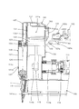
以下、本発明の実施形態につき、図1〜図5を参照しつつ詳細に説明する。本実施の形態は、電気−空気式打込み工具の一例として電気−空気式釘打機を用いて説明する。図1に示すように、釘打機100は、概括的に見て、工具本体としての本体部101と、作業者が握る長尺状のハンドル部103と、被加工材に打ち込まれる止具としての釘nが装填されるマガジン105とを主体として構成される。ハンドル部103は、本体部101の長軸方向(図1〜図5の上下方向)の一端側(図示上側)の側面部から当該長軸方向と交差する側方(図示右側)に向って突き出る状態で一体状に設けられている。ハンドル部103の突出側端部には、駆動モータ111の電源となる充電式のバッテリパック110が装着されている。なお、図1〜図5には釘打機100の下向き状態、すなわち本体部101の先端部(図示下端部)が被加工材に向けられた状態が示される。このため、図1〜図5において下向き方向が釘nの打込み(発射)方向(長軸方向)であり、ドライバ125による釘nの打撃方向となる。
Hereinafter, embodiments of the present invention will be described in detail with reference to FIGS. This embodiment will be described using an electro-pneumatic nailing machine as an example of an electro-pneumatic driving tool. As shown in FIG. 1, the nailing
本体部101は、釘打込み機構120の打撃用シリンダ121及び圧縮装置130の圧縮用シリンダ131が一体状に形成された本体ハウジング107と、駆動モータ111が収容されたモータハウジング109とを主体として構成される。モータハウジング109は、本体ハウジング107の先端側(下端側)において、ハンドル部103に対し所定の間隔を置いて概ね並行に配置されるとともに、長軸方向の一端側が本体ハウジング107に連接され、他端側がハンドル部103の突出側端部に連接されている。
The
本体ハウジング107における打撃用シリンダ121の先端部(図1〜図5において下方)には、釘nの射出口を構成するドライバガイド141が配置されている。マガジン105は、本体部101の最先端側において、モータハウジング109に近接した状態で当該モータハウジング109と概ね並行に配置され、釘供給側先端部がドライバガイド141に連結され、他端側がモータハウジング109の他端部に連接されている。なお、マガジン105には、便宜上図示を省略するが、釘nを供給方向(図1〜図5において左方)に押すためのプッシャプレートが備えられ、このプッシャプレートによって釘nがドライバガイド141の打込み通路141aに打込み方向と交差する方向から1本ずつ供給されるよう構成されている。なお、説明の便宜上、本体部101の長軸方向の先端側(図示下側)を前、その反対側を後という。
A
釘打込み機構120の打撃用シリンダ121と、圧縮装置130の圧縮用シリンダ131とは、それらの長軸方向が互いに平行となるように形成されている。打撃用シリンダ121内には、釘nを打撃動作する打撃用ピストン123が長軸方向に摺動自在に収容されている。打撃用シリンダ121は、本発明における「シリンダ」に対応する。打撃用ピストン123は、打撃用シリンダ121内に摺動自在に収容されたピストン本体部124と、当該ピストン本体部124に一体状に設けられ、釘nを打撃動作するための長尺状のドライバ125とからなり、打撃用シリンダ121の長軸方向に直線状に移動し、ドライバ125がドライバガイド141の打込み通路141a内を前方に移動して釘nを打込む作動部材として機能する。打撃用ピストン123は、本発明における「ピストン」に対応し、ピストン本体部124は、本発明における「摺動部」に対応し、ドライバ125は、本発明における「打込み部」に対応する。打撃用シリンダ121及び打撃用ピストン123によって釘打込み機構120が構成される。
The
圧縮装置130の圧縮用シリンダ131内には、圧縮用ピストン133が長軸方向に摺動自在に収容され、当該圧縮用ピストン133は、駆動モータ111からクランク機構115を介して駆動される。駆動モータ111は回転軸線が圧縮用シリンダ131の長軸方向と交差するようにモータハウジング109内に配置されている。そして、駆動モータ111の回転出力は、歯車減速機構113によって適宜減速されるとともに、運動変換機構としてのクランク機構115によって直線運動に変換されて圧縮用ピストン133を直線状に往復運動させる。これにより圧縮用シリンダ131の内部空間である圧縮室131aの容積が変化し、圧縮用ピストン133が圧縮室131aを減少する後方側へと移動することで圧縮室131aの空気が圧縮される。すなわち、本実施の形態では、圧縮装置130として、圧縮用シリンダ131、圧縮用ピストン133及びクランク機構115を主体として構成されるレシプロ式の圧縮装置が用いられている。
A
なお、クランク機構115は、歯車減速機構113によって減速回転されるクランク軸115aと、クランク軸115aの回転中心から偏心した位置に設けられた偏心ピン115bと、偏心ピン115bに一端が相対回動自在に連接され、他端が圧縮用ピストン133に相対回動自在に連接された連接ロッド115cとによって構成されており、圧縮用シリンダ131の前方領域において、本体ハウジング107の内部に収容されている。
The
なお、駆動モータ111は、ハンドル部103に支軸103cを支点にして回動自在に設けたトリガ103a及び本体部101の先端領域に設けられるコンタクトアーム(本実施の形態では、ドライバガイド141がコンタクトアームの機能を兼ね備える構成とされる)によって駆動と停止が制御される構成とされる。すなわち、ハンドル部103には、手指により操作可能なトリガ103aと、当該トリガ103aが引き操作されることで駆動モータ111を通電駆動するオン状態に投入され、引き操作が解除されることで駆動モータ111を停止するオフ状態に切替わるモータ駆動用のトリガスイッチ103bが設置されている。
The
他方、コンタクトアームを兼ねるドライバガイド141(以下の説明では、ドライバガイド141がコンタクトアームとして機能する場合に限り、コンタクトアーム141という)は、釘nの長軸方向(打撃方向)に移動可能に取り付けられ、便宜上図示を省略するバネにより先端側に突出するように付勢されている。コンタクトアーム141が突出位置にあるときは、便宜上図示を省略するモータ駆動用のコンタクトアームスイッチがオフ状態とされ、コンタクトアーム141が本体ハウジング107側に移動されたときに、コンタクトアームスイッチがオン状態とされる。そして、駆動モータ111は、トリガスイッチ103bとコンタクトアームスイッチが共にオン状態に切替えられたときに通電駆動され、いずれか一方、又は双方がオフ状態に切替えられたとき停止される。トリガ103a及びコンタクトアーム141が、本発明における「制御部材」に対応する。
On the other hand, a
本体ハウジング107には、圧縮用シリンダ131の圧縮室131aと打撃用シリンダ121の内部とを連通する連通路135と、当該連通路135を開放及び閉鎖するメインバルブ137が設けられている。連通路135は、本発明における「圧縮空気供給経路」に対応し、メインバルブ137は、本発明における「開閉装置」に対応する。釘打機100は、図1に示すように、打撃用ピストン123が最後端位置(図示上端位置)へと移動され、かつ圧縮用ピストン133が最前端位置(下死点)へと移動された状態が初期位置として定められている。メインバルブ137は、圧縮用シリンダ131のシリンダヘッド側に設けられるとともに、非通電時に閉じる電気的駆動弁としてのノーマルクローズタイプのソレノイドバルブによって構成されており、圧縮用ピストン133が最後端位置へと移動された上死点付近において連通路135を開放する構成とされる。従って、メインバルブ137が連通路135を開放すると、圧縮用ピストン133で圧縮された圧縮室131a内の圧縮空気が打撃用シリンダ121へと供給され、この供給された圧縮空気によって打撃用ピストン123が前方へと移動され、ドライバ125によって釘nを打撃し、被加工材に釘nを打込む。
The
打撃用シリンダ121には、釘打ち作業終了時、あるいは終了直前において、打撃用シリンダ121内の圧縮空気を大気中に逃がす逆止弁127a付きの逃し孔127が形成されている。当該逃し孔127は、打撃用ピストン123が最前端位置へと移動(図3に示す位置参照)されたときに、当該打撃用ピストン123のピストン本体部124が通過して打撃用シリンダ121内部を大気に連通させる位置に設けられる。すなわち、ドライバ125による釘打ちが終了すると同時に大気と打撃用シリンダ121の内部とを連通する構成とされ、これによって打撃終了と同時に打撃用シリンダ121内の圧縮空気は、大気中に放出される。なお、逆止弁127aは、打撃用シリンダ121の外側において、逃し孔127を塞ぐように配置された板バネによって構成されており、大気中の空気が逃し孔127から打撃用シリンダ121内に流入(逆流)することを規制する。
The hitting
圧縮動作後の圧縮用ピストン133が前方へと移動すると、圧縮室131aの容積が増加され、これによって当該圧縮室131a及び打撃用シリンダ121内が負圧化し、当該負圧によって打撃用ピストン123が後方へと移動される構成とされる(図4参照)。また、圧縮用シリンダ131には、圧縮用ピストン133が初期位置としての最前端位置(下死点)に置かれたときに、当該圧縮用ピストン133のピストン本体部133aが通過することで大気と圧縮室131aとを連通する外気補給口139が設けられる。そして、メインバルブ137は、圧縮用ピストン133のピストン本体部133aが外気補給口139を通過して最前端位置(下死点)に置かれたとき、連通路135を閉鎖するように構成される。このように、本実施の形態に係る釘打機100による釘打ち動作は、圧縮用ピストン133が一往復すると、打撃用ピストン123のドライバ125が一回の釘打込み動作を行うように構成されている。
When the
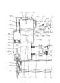
次に上記のように構成された釘打機100の作用および使用方法につき説明する。図1に示す初期状態において、コンタクトアーム141が被加工材に押し付けられてコンタクトアームスイッチがオン状態とされるとともに、トリガ103aが引き操作されてトリガスイッチ103bがオン状態に切替えられると、駆動モータ111が通電駆動される。これによって歯車減速機構113を介してクランク機構115が駆動され、圧縮用ピストン133が後方へと移動を開始し、外気補給口139による圧縮室131aと大気との連通が遮断される。このとき、メインバルブ137は、連通路135を閉鎖しており、このため、圧縮室131aの容積が減少され、圧縮室131a内に閉じ込められた空気が圧縮される。圧縮途中の状態が図2に示される。
Next, the operation and method of use of the nailing
圧縮用ピストン133が最後端位置に接近した圧縮動作の上死点付近でメインバルブ137が通電されて連通路135を開放する。このため、圧縮室131a内の圧縮空気が連通路135を経て打撃用シリンダ121内へと供給され、当該圧縮空気によって打撃用ピストン123が前方へ移動される。そして、前方へと移動された打撃用ピストン123のドライバ125がドライバガイド141の打込み通路141aに待機している釘nを打撃し、これを被加工材に打込む。この状態が図3に示される。
The
打撃用ピストン123のピストン本体部124が逃し孔127を通過すると、打撃用シリンダ121内の圧縮空気が逃し孔127を通して大気中に放出される。と同時に最後端位置の圧縮用ピストン133が方向を転換して前方へと移動される。この前方への移動により圧縮室131aの容積が増加されて当該圧縮室131aが負圧化され、当該負圧が連通路135及び打撃用シリンダ121内を通じて打撃用ピストン123に作用する。これによって打撃用ピストン123が吸引され、後方の打撃前の位置へと戻される。この戻し途中状態が図4に示される。
When the piston
なお、圧縮用ピストン133が初期位置としての圧縮開始前の位置(下死点)に復帰すると、外気補給口139が開き、圧縮室131a内に大気中の空気が補給される。また、圧縮用ピストン133が圧縮開始前の位置に復帰すると、トリガスイッチ103b及びコンタクトアームスイッチのオン状態に維持されていても、駆動モータ111に対する通電が遮断され、駆動モータ111が停止され、同時にメインバルブ137に対する通電が遮断され、当該メインバルブ137が連通路135を閉鎖する。かくして、釘打ち動作の1サイクルが終了する。
When the
なお、駆動モータ111に対する通電の遮断、及びメインバルブ137に対する通電とその遮断については、便宜上図示を省略するが、例えば、クランク軸115aの回転角度、あるいは偏心ピン115bの位置等を適宜位置検知センサーによって検知し、当該検知信号に基づき、少なくとも駆動モータ111を制御するべく設けられる制御装置(コントローラ)によって制御されるように構成される。
The illustration of the interruption of energization to the
上記のように、本実施の形態に係る電気−空圧式の釘打機100は、バッテリパック110を電源として駆動する駆動モータ111を用いて圧縮装置130を駆動し、そして当該圧縮装置130によって生成した圧縮空気を用いて打撃用ピストン123を直線状に移動させて釘nをドライバ125によって打込む構成としている。このため、外部の電源を釘打機に供給するための電源コード、及び外部の圧縮空気源から圧縮空気を釘打機に供給するためのエアホースのいずれもが不要とされた、コードレスでかつホースレスの釘打機が構成されることとなり、使用性の高い釘打機が提供される。
As described above, the electro-
ところで、上記のように構成され、かつ作用する釘打機100においては、釘打ち動作に関連する機能部材としての、トリガ103a、駆動モータ111、圧縮装置130、釘打込み機構120等によって構成される釘打機100の内部機構のうち、少なくとも一つが正常な動作状態として許容される範囲から逸脱した動作状態(以下、この動作状態を非定常動作状態という)になることが考えられる。その一例としては、例えば圧縮装置130の圧縮途中において、作業者がコンタクトアーム141の被加工材に対する押し付け動作を解除すること、あるいはトリガ103aの引き操作を解除することが考えられる。つまり釘打ち動作を途中で止める場合がある。この場合、圧縮室131a内に圧縮空気が貯留した状態で駆動モータ111が停止することになる。そして、この状態で、メインバルブ137が何らかの原因で不用意に開かれると、圧縮室131aの圧縮空気が打撃用シリンダ121に供給されてしまい、予期しない打撃動作が行なわれる可能性があり、一方、メインバルブ137が開かれない場合には、次の起動時に圧縮室131a内に残留する圧縮空気が原因となって駆動モータ111あるいは圧縮装置130等に過大な負荷が作用する可能性がある。
By the way, the nailing
そこで、上記のような不具合を解決するべく、本実施の形態では、圧縮装置130の圧縮室131aの圧力を大気に開放可能な大気開放バルブ151を設けている。そして、圧縮装置130の圧縮途中において、作業者がトリガ103aの引き操作を解除した場合、あるいはコンタクトアーム141の被加工材に対する押し付け動作を解除した場合に、大気開放バルブ151を開くことで大気開放通路153を通じて圧縮室131aの圧力を大気に開放し、これによって打撃用ピストン123へのエネルギ伝達を遮断する構成としている。大気開放バルブ151は、本発明における「大気開放バルブ」に対応し、大気開放通路153は、本発明における「大気開放経路」に対応し、大気開放バルブ151と大気開放通路153により大気開放装置が構成される。また、圧縮装置130の圧縮途中において、作業者がトリガ103aの引き操作を解除した場合、あるいはコンタクトアーム141の被加工材に対する押し付け動作を解除した場合が、本発明における「内部機構の所定の動作状態」に対応する。
Therefore, in order to solve the above-described problems, in the present embodiment, an
図1〜図5に示すように、圧縮用シリンダ131の後端部(ヘッド側)には、圧縮室131a内の圧力を大気に開放する大気開放通路153と、当該大気開放通路153を開放及び閉鎖する大気開放バルブ151が設けられている。大気開放バルブ151は、非通電時に大気開放通路153を開放する電気的駆動弁としてのノーマルオープンタイプのソレノイドバルブによって構成されており、通電時に大気開放通路153を閉鎖するように構成される。
As shown in FIGS. 1 to 5, at the rear end portion (head side) of the
そして、本実施の形態では、トリガ103aが引き操作されてトリガスイッチ103bがオン状態とされ、かつコンタクトアーム141が被加工材に押し付けられてコンタクトアームスイッチがオン状態とされたとき(駆動モータ111が通電駆動されたとき)に、大気開放バルブ151が通電状態とされ、トリガスイッチ103b又はコンタクトアームスイッチのいずれか一方がオフ状態とされたときに、大気開放バルブ151が非通電状態とされるよう構成される。トリガ103a、トリガスイッチ103b、コンタクトアーム141及びコンタクトアームスイッチが、本発明における「制御部材」に対応に対応する。
In the present embodiment, when the trigger 103a is pulled and the
本実施の形態は、上記のように構成したものである。従って、作業者が釘打ち作業するべく、コンタクトアーム141を被加工材に押し付けるとともに、トリガ103aを引き操作すると、コンタクトアームスイッチとトリガスイッチ103bが共にオン状態となる。このため、大気開放バルブ151が通電されることで、当該大気開放バルブ151が閉じ側に作動され、大気開放通路153を閉鎖する。このとき、前述したようにコンタクトアームスイッチとトリガスイッチ103bが共にオン状態とされることで駆動モータ111が通電駆動されるので、圧縮装置130、釘打込み機構120を介して一連の釘打ち動作が遂行されることになる。
The present embodiment is configured as described above. Therefore, when the operator pushes the
一方、作業者が動作途中でトリガ103aの引き操作を解除すると、あるいは被加工材に対するコンタクトアーム141の押し付け動作を解除すると、トリガスイッチ103bあるいはコンタクトアームスイッチがオフ状態とされ、駆動モータ111が停止するため、通常であれば、圧縮装置130の圧縮室131a内に圧縮空気が貯留されたままとなる。しかるに、本実施の形態によれば、トリガスイッチ103bあるいはコンタクトアームスイッチがオフ状態とされることで、大気開放バルブ151が非通電となり、大気開放バルブ151が開き側に作動され(内蔵バネによる)、大気開放通路153を開放する。この状態が図5に示される。すなわち、大気開放バルブ151は、トリガ103a又はコンタクトアーム141の操作解除動作に連動して開き側に切替えられる。このため、圧縮室131aの圧縮空気が大気に放出され、圧縮装置130から釘打込み機構120へのエネルギ伝達が遮断されることになる。従って、圧縮装置130の圧縮途中での停止状態において、メインバルブ137が開放されても、ドライバ125による釘打ち動作が遂行されることがない。すなわち、本実施の形態によれば、大気開放バルブ151を開放側に作動させることで、釘nの打込み動作を不能化し、釘nの不測の打込み動作を防止することができる。また、次の起動時に圧縮室131a内に残留する圧縮空気が原因となって駆動モータ111あるいは圧縮装置130等に過大な負荷が作用することもなく、駆動モータ111あるいは圧縮装置130等を過負荷から保護することができる。
On the other hand, when the operator cancels the pulling operation of the trigger 103a during the operation, or cancels the pressing operation of the
また、本実施の形態では、釘打ち終了時においては、打撃用ピストン123が釘打ち動作前の初期位置に復帰したことを適宜位置検知センサーによって検知したとき、当該検知信号に基づいて前記制御装置(コントローラ)が大気開放バルブ151を開放側に切替えるように構成されている。このように、打撃用ピストン123の初期位置への復帰を待って大気開放バルブ151が開放側に切替わる構成としたことにより、打撃用ピストン123が初期位置に復帰するまで圧縮室131a及び打撃用シリンダ121内の負圧状態を確実に維持する。すなわち、定常動作状態では、大気開放バルブ151は釘打込み動作の正常サイクルをキープする部材として機能する。なお、このときの、大気開放バルブ151のコントローラの指令による開放側への切替わりは、作業者によるトリガ103aの引き操作及びコンタクトアーム141の被加工材に対する押し付け動作がそれぞれ継続されることでトリガスイッチ103b及びコンタクトアーム141が共にオン状態にあっても遂行されるように構成される。
In the present embodiment, when the nail driving is finished, when the position detection sensor appropriately detects that the
次に、本発明の他の実施形態につき説明する。図6に示す変形例では、釘打込み機構120における打撃用シリンダ121のシリンダヘッド側に大気開放バルブ151を設ける構成としている。圧縮室131aと打撃用シリンダ121内とをつなぐ連通路135の空気流れ方向の途中領域に、当該連通路135と大気とを連通する大気開放通路153が設定され、当該大気開放通路153が大気開放バルブ151によって開放及び閉鎖される構成としている。大気開放バルブ151は、ノーマルオープンタイプのソレノイドバルブとして構成される。また、大気開放バルブ151が開き側に動作されたときには、メインバルブ137も同じく開き側に動作されるように構成される。なお、上記以外の構成については、前述した実施の形態と同様に構成される。
Next, another embodiment of the present invention will be described. In the modification shown in FIG. 6, the
従って、本実施の形態によれば、作業者が動作途中でトリガ103aの引き操作を解除した場合には、あるいは被加工材に対するコンタクトアーム141の押し付け動作を解除した場合には、メインバルブ137が開き側に作動して連通路135を開放するとともに、大気開放バルブ151が開き側に作動して大気開放通路153を開放する。この状態が図6に示される。このため、圧縮室131a及び打撃用シリンダ121内が共に大気に連通されることになり、圧縮装置130と釘打込み機構120間でのエネルギ伝達を遮断し、ドライバ125による釘nの不測の打込み動作を防止することができる。
Therefore, according to the present embodiment, when the operator releases the pulling operation of the trigger 103a during the operation, or when the pressing operation of the
次に、大気開放バルブ15を開放側に切替える条件を定める「内部機構の所定の動作状態、換言すれば非定常動作状態」に関する変形例につき説明する。 Next, a modified example relating to “a predetermined operating state of the internal mechanism, in other words, an unsteady operating state” that defines a condition for switching the atmosphere release valve 15 to the open side will be described.
〔変形例1〕
変形例1では、便宜上図示を省略するが、内部機構の非定常動作状態は、作業者によって操作可能とされた駆動モータ111の駆動と停止を制御する制御部材としてのトリガ103a又はコンタクトアーム141の動作状態によって定められる。具体的には、トリガ103a又はコンタクトアーム141のいずれか一方が当該スイッチをオン状態に投入する位置に不意にロックされて初期位置に復帰できなくなったとき、あるいはトリガ103a又はコンタクトアーム141が復帰したにも拘らず、それらによって操作されたスイッチのオン状態が維持されたままであるときに、トリガ103a又はコンタクトアーム141が非定常動作状態にあると設定する。そして、このことを検知する検知装置を設け、当該検知装置の検知に基づき制御装置によって大気開放バルブ15を開放側に切替える構成とされる。
[Modification 1]
In the first modification, although not shown for convenience, the unsteady operation state of the internal mechanism is that the trigger 103a or the
〔変形例2〕
変形例2では、便宜上図示を省略するが、内部機構の非定常動作状態は、圧縮装置130の動作状態で定められる。具体的には、駆動モータ111の回転出力を圧縮装置130に伝達する歯車減速機構113によって構成される動力伝達機構、あるいはクランク機構115が動作途中で停止したときに、圧縮装置130が非定常動作状態にあると設定する。そして、このことを検知する検知装置を設け、当該検知装置の検知に基づき制御装置によって大気開放バルブ151を開放側に切替える構成とされる。
[Modification 2]
In Modification 2, although not shown for convenience, the unsteady operation state of the internal mechanism is determined by the operation state of the
〔変形例3〕
変形例3では、便宜上図示を省略するが、内部機構の非定常動作状態は、圧縮室131aの圧力値で定められる。具体的には、圧縮室131aの圧力が異常に上昇し、当該上昇圧力が予め定めた設定圧力に達したとき、あるいは超えたときに、圧縮室131aの圧力が非定常状態にあると設定する。そして、このことを検知する検知装置を設け、当該検知装置の検知に基づき制御装置によって大気開放バルブ15を開放側に切替える構成とされる。
[Modification 3]
In modification 3, although illustration is omitted for convenience, the unsteady operation state of the internal mechanism is determined by the pressure value of the
〔変形例4〕
変形例3では、便宜上図示を省略するが、内部機構の非定常動作状態は、メインバルブ137の動作状態で定められる。具体的には、メインバルブ137が本来開放動作すべきタイミング(圧縮用ピストン133が下死点に接近した状態)で開放動作しなかったときに、メインバルブ137が作動不良であると設定する。そして、このことを検知する検知装置を設け、当該検知装置の検知に基づき制御装置によって大気開放バルブ151を開放側に切替える構成とされる。
[Modification 4]
In Modification 3, although not shown for convenience, the unsteady operation state of the internal mechanism is determined by the operation state of the
〔変形例5〕
変形例5では、便宜上図示を省略するが、内部機構の非定常動作状態は、内部機構の温度値で定められる。具体的には、内部機構のうちの圧縮装置130、駆動モータ111、あるいはバッテリパック110の温度値が異常に高くなったようなときに、圧縮装置130、駆動モータ111、あるいはバッテリパック110が異常な状態にあると設定する。そして、このことを検知する検知装置を設け、当該検知装置の検知に基づき制御装置によって大気開放バルブ151を開放側に切替える構成とされる。上記の圧縮装置130、駆動モータ111、あるいはバッテリパック110の温度値が、本発明における「エネルギの供給状態」に対応する。
[Modification 5]
In modification 5, although illustration is omitted for convenience, the unsteady operation state of the internal mechanism is determined by the temperature value of the internal mechanism. Specifically, when the temperature value of the
〔変形例6〕
変形例6では、便宜上図示を省略するが、内部機構の非定常動作状態は、内部機構の電流値又は電圧値で定められる。具体的には、バッテリパック110から駆動モータ111へと供給される電流値又は電圧値が、予め定めた設定値を超えるような異常な値を示したときに、バッテリパック110又は駆動モータ111が異常な状態にあると設定する。そして、このことを検知する検知装置を設け、当該検知装置の検知に基づき制御装置によって大気開放バルブ151を開放側に切替える構成とされる。上記のバッテリパック110から駆動モータ111へと供給される電流値又は電圧値が、本発明における「エネルギの供給状態」に対応する。
[Modification 6]
In modification 6, although illustration is omitted for convenience, the unsteady operation state of the internal mechanism is determined by the current value or voltage value of the internal mechanism. Specifically, when the current value or voltage value supplied from the
なお、大気開放バルブ151は、上述した内部機構の非定常動作状態のうちの、一つの非定常動作状態が検知されたときに切替わる構成してもよいし、複数の非定常動作状態が検知されたときに切替わるように構成してもよい。
The
100 釘打機(打込み工具)
101 本体部
103 ハンドル部
103a トリガ
103b トリガスイッチ
103c 支軸
105 マガジン
107 本体ハウジング
109 モータハウジング
110 バッテリパック
111 駆動モータ(モータ)
113 歯車減速機構
115 クランク機構
115a クランク軸
115b 偏心ピン
115c 連接ロッド
120 釘打込み機構
121 打撃用シリンダ(シリンダ)
123 打撃用ピストン(ピストン)
124 ピストン本体部(摺動部)
125 ドライバ(打込み部)
127 逃し孔
127a 逆止弁
130 圧縮装置
131 圧縮用シリンダ
133 圧縮用ピストン
133a ピストン本体部
135 連通路(圧縮空気供給経路)
137 メインバルブ(開閉装置)
139 外気補給口
141 ドライバガイド(コンタクトアーム)
141a 打込み通路
151 大気開放バルブ
153 大気開放通路
100 nailing machine (driving tool)
101
113
123 Stroke piston (piston)
124 Piston body (sliding part)
125 driver (driving part)
127 Relief hole
137 Main valve (opening / closing device)
139 Outside
141a Implanting
Claims (12)
前記シリンダに摺動自在に収容された摺動部及び当該摺動部に設けられるとともに止具を打込む長尺状の打込み部を備えたピストンと、
バッテリと、
前記バッテリから供給される電力で駆動されるモータと、
前記モータによって駆動されて圧縮室の容積変化により圧縮空気を生成する圧縮装置と、
前記圧縮室の空気を前記シリンダ内に供給する圧縮空気供給経路と、
前記圧縮空気供給経路を開放及び閉鎖する開閉装置と、
前記モータの駆動と停止を制御するための制御部材と、
を有し、
前記圧縮装置によって圧縮された前記圧縮室内の圧縮空気を前記開閉装置の開放動作を介して前記シリンダ内へと供給し、当該圧縮空気によって前記ピストンを直線状に移動させ、当該ピストンの打込み部により前記止具の打込み作業を遂行する打込み工具であって、
前記圧縮室又はシリンダ内と大気とを連通する大気開放経路を有し、前記大気開放経路には、当該大気開放経路の開放及び閉鎖を切替可能な大気開放バルブが設けられていることを特徴とする打込み工具。 A cylinder,
A piston provided with a sliding portion that is slidably accommodated in the cylinder, and a long driving portion that is provided on the sliding portion and drives a stopper;
Battery,
A motor driven by electric power supplied from the battery;
A compressor that is driven by the motor to generate compressed air by changing the volume of the compression chamber;
A compressed air supply path for supplying air in the compression chamber into the cylinder;
An opening and closing device for opening and closing the compressed air supply path;
A control member for controlling driving and stopping of the motor;
Have
Compressed air in the compression chamber compressed by the compression device is supplied into the cylinder through an opening operation of the opening / closing device, and the piston is moved linearly by the compressed air, and is driven by a driving portion of the piston. A driving tool for performing the driving operation of the stopper,
An air release path that communicates the inside of the compression chamber or cylinder and the atmosphere, and the atmosphere release path is provided with an atmosphere release valve that can switch between opening and closing of the atmosphere release path. Driving tool to do.
前記バッテリ、前記モータ、前記圧縮装置、前記開閉装置、前記ピストン及び前記制御部材で定義される内部機構の所定の動作状態に応じて前記大気開放バルブを切替えることを特徴とする打込み工具。 The driving tool according to claim 1,
A driving tool for switching the atmosphere release valve according to a predetermined operation state of an internal mechanism defined by the battery, the motor, the compression device, the switching device, the piston, and the control member.
前記内部機構の動作状態を検知する検知手段を有し、当該検知手段が前記内部機構の所定の動作状態を検知したときに前記大気開放バルブを切替えることを特徴とする打込み工具。 The driving tool according to claim 2,
A driving tool comprising detecting means for detecting an operating state of the internal mechanism, and switching the atmosphere release valve when the detecting means detects a predetermined operating state of the internal mechanism.
前記所定の動作状態は、前記モータの駆動と停止を制御する前記制御部材の動作状態で定められることを特徴とする打込み工具。 The driving tool according to claim 2,
The driving tool according to claim 1, wherein the predetermined operation state is determined by an operation state of the control member that controls driving and stopping of the motor.
前記制御部材は、作業者による引き操作によって前記モータを通電駆動させ、引き操作の解除によって前記モータを停止させるトリガであることを特徴とする打込み工具。 The driving tool according to claim 4,
The driving tool, wherein the control member is a trigger that energizes and drives the motor by a pulling operation by an operator and stops the motor by releasing the pulling operation.
前記所定の動作状態は、前記圧縮装置の動作状態で定められることを特徴とする打込み工具。 A driving tool according to claim 3, wherein
The driving tool according to claim 1, wherein the predetermined operation state is determined by an operation state of the compression device.
前記所定の動作状態は、前記ピストンの動作状態で定められることを特徴とする打込み工具。 A driving tool according to claim 3, wherein
The driving tool according to claim 1, wherein the predetermined operation state is determined by an operation state of the piston.
前記所定の動作状態は、前記圧縮室の圧力値で定められることを特徴とする打込み工具。 The position setting tool according to claim 3,
The driving tool according to claim 1, wherein the predetermined operation state is determined by a pressure value of the compression chamber.
前記所定の動作状態は、前記開閉装置の動作状態で定められることを特徴とする打込み工具。 A driving tool according to claim 3, wherein
The driving tool according to claim 1, wherein the predetermined operating state is determined by an operating state of the switchgear.
前記所定の動作状態は、前記圧縮装置へのエネルギの供給状態で定められることを特徴とする打込み工具。 A driving tool according to claim 3, wherein
The driving tool according to claim 1, wherein the predetermined operation state is determined by a supply state of energy to the compression device.
前記所定の動作状態は、請求項4及び請求項6〜10において定められる所定の動作状態のうちの複数要素の相関状態によって定められることを特徴とする打込み工具。 A driving tool according to claim 3, wherein
The predetermined operation state is determined by a correlation state of a plurality of elements among the predetermined operation states defined in claims 4 and 6 to 10.
前記大気開放バルブは、ソレノイドバルブであることを特徴とする打込み工具。 The driving tool according to claim 1 or 2,
The driving tool according to claim 1, wherein the air release valve is a solenoid valve.
Priority Applications (3)
| Application Number | Priority Date | Filing Date | Title |
|---|---|---|---|
| JP2009173703A JP2012187640A (en) | 2009-07-24 | 2009-07-24 | Hammering tool |
| JP2011523588A JPWO2011010512A1 (en) | 2009-07-24 | 2010-06-09 | Driving tool |
| PCT/JP2010/059787 WO2011010512A1 (en) | 2009-07-24 | 2010-06-09 | Hammering tool |
Applications Claiming Priority (1)
| Application Number | Priority Date | Filing Date | Title |
|---|---|---|---|
| JP2009173703A JP2012187640A (en) | 2009-07-24 | 2009-07-24 | Hammering tool |
Publications (1)
| Publication Number | Publication Date |
|---|---|
| JP2012187640A true JP2012187640A (en) | 2012-10-04 |
Family
ID=43498988
Family Applications (2)
| Application Number | Title | Priority Date | Filing Date |
|---|---|---|---|
| JP2009173703A Pending JP2012187640A (en) | 2009-07-24 | 2009-07-24 | Hammering tool |
| JP2011523588A Pending JPWO2011010512A1 (en) | 2009-07-24 | 2010-06-09 | Driving tool |
Family Applications After (1)
| Application Number | Title | Priority Date | Filing Date |
|---|---|---|---|
| JP2011523588A Pending JPWO2011010512A1 (en) | 2009-07-24 | 2010-06-09 | Driving tool |
Country Status (2)
| Country | Link |
|---|---|
| JP (2) | JP2012187640A (en) |
| WO (1) | WO2011010512A1 (en) |
Families Citing this family (15)
| Publication number | Priority date | Publication date | Assignee | Title |
|---|---|---|---|---|
| JP5859372B2 (en) * | 2012-04-27 | 2016-02-10 | 株式会社マキタ | Driving tool |
| JP2014108495A (en) * | 2012-12-03 | 2014-06-12 | Makita Corp | Driving tool |
| US9662777B2 (en) | 2013-08-22 | 2017-05-30 | Techtronic Power Tools Technology Limited | Pneumatic fastener driver |
| WO2015037299A1 (en) * | 2013-09-10 | 2015-03-19 | 株式会社マキタ | Driving tool |
| WO2016136632A1 (en) * | 2015-02-26 | 2016-09-01 | 日立工機株式会社 | Driving machine |
| CN113084757A (en) * | 2015-04-30 | 2021-07-09 | 工机控股株式会社 | Driving machine |
| WO2017056810A1 (en) * | 2015-09-30 | 2017-04-06 | 日立工機株式会社 | Driver |
| CN108058142A (en) * | 2016-11-09 | 2018-05-22 | 创科(澳门离岸商业服务)有限公司 | For the control system of gas spring fastener driver |
| US11110577B2 (en) | 2017-11-16 | 2021-09-07 | Milwaukee Electric Tool Corporation | Pneumatic fastener driver |
| WO2019208102A1 (en) * | 2018-04-24 | 2019-10-31 | 工機ホールディングス株式会社 | Driving tool |
| DE102018117519A1 (en) * | 2018-07-19 | 2020-01-23 | Prebena Wilfried Bornemann Gmbh & Co. Kg | Compressed air driven device |
| US11819989B2 (en) | 2020-07-07 | 2023-11-21 | Techtronic Cordless Gp | Powered fastener driver |
| CA3167425A1 (en) * | 2021-07-16 | 2023-01-16 | Techtronic Cordless Gp | Powered fastener driver |
| WO2023176711A1 (en) * | 2022-03-16 | 2023-09-21 | 工機ホールディングス株式会社 | Work machine |
| CN115119627B (en) * | 2022-08-10 | 2023-06-09 | 徐帅 | Cutting knife blocking prevention header for harvester and working method thereof |
Family Cites Families (3)
| Publication number | Priority date | Publication date | Assignee | Title |
|---|---|---|---|---|
| JPS58188175U (en) * | 1982-06-07 | 1983-12-14 | マックス株式会社 | pneumatic nailer safety valve |
| JPH0747270B2 (en) * | 1986-09-13 | 1995-05-24 | 松下電工株式会社 | Battery powered nailer |
| JP3676879B2 (en) * | 1995-07-25 | 2005-07-27 | 株式会社マキタ | Fastener driving tool |
-
2009
- 2009-07-24 JP JP2009173703A patent/JP2012187640A/en active Pending
-
2010
- 2010-06-09 JP JP2011523588A patent/JPWO2011010512A1/en active Pending
- 2010-06-09 WO PCT/JP2010/059787 patent/WO2011010512A1/en active Application Filing
Also Published As
| Publication number | Publication date |
|---|---|
| WO2011010512A1 (en) | 2011-01-27 |
| JPWO2011010512A1 (en) | 2012-12-27 |
Similar Documents
| Publication | Publication Date | Title |
|---|---|---|
| JP2012187640A (en) | Hammering tool | |
| WO2011010511A1 (en) | Hammering tool | |
| JP2012148346A (en) | Hammering tool | |
| US10286534B2 (en) | Driving tool | |
| JP2011025362A (en) | Driving tool | |
| JP6408944B2 (en) | Driving tool | |
| US9943952B2 (en) | Driving tool | |
| USRE44001E1 (en) | Fastener driving apparatus | |
| US10272553B2 (en) | Driving tool | |
| EP3156180B1 (en) | Fastener driving machine | |
| JP6950423B2 (en) | Driving tool | |
| JP2011025363A (en) | Hammering tool | |
| JP6833565B2 (en) | Driving tool | |
| US20110180581A1 (en) | Resetting and Driving Mechanism for Nail Driving Rod in Pneumatic Nailer having Embedded Air Compressor | |
| US7422134B2 (en) | Variable outward clinch stapler | |
| WO2013168719A1 (en) | Driving tool | |
| JP7108369B2 (en) | Air nailer with single shot and contact trigger | |
| JP2014108495A (en) | Driving tool | |
| US10118283B2 (en) | Hand-held tool | |
| TWI769320B (en) | Break in tool | |
| CN218927701U (en) | Blank fire locking and last position fastener retention mechanism for power fastener driver | |
| JP2012148347A (en) | Hammering tool | |
| JP3948349B2 (en) | Air nailer | |
| CN111727106A (en) | Driving machine | |
| CN219649807U (en) | Nail gun and electric tool |