WO2016136536A1 - 作業車両 - Google Patents
作業車両 Download PDFInfo
- Publication number
- WO2016136536A1 WO2016136536A1 PCT/JP2016/054469 JP2016054469W WO2016136536A1 WO 2016136536 A1 WO2016136536 A1 WO 2016136536A1 JP 2016054469 W JP2016054469 W JP 2016054469W WO 2016136536 A1 WO2016136536 A1 WO 2016136536A1
- Authority
- WO
- WIPO (PCT)
- Prior art keywords
- vehicle
- work
- lift cylinder
- imaging unit
- work vehicle
- Prior art date
- Legal status (The legal status is an assumption and is not a legal conclusion. Google has not performed a legal analysis and makes no representation as to the accuracy of the status listed.)
- Ceased
Links
Images









Classifications
-
- E—FIXED CONSTRUCTIONS
- E02—HYDRAULIC ENGINEERING; FOUNDATIONS; SOIL SHIFTING
- E02F—DREDGING; SOIL-SHIFTING
- E02F3/00—Dredgers; Soil-shifting machines
- E02F3/04—Dredgers; Soil-shifting machines mechanically-driven
- E02F3/76—Graders, bulldozers, or the like with scraper plates or ploughshare-like elements; Levelling scarifying devices
- E02F3/80—Component parts
-
- E—FIXED CONSTRUCTIONS
- E02—HYDRAULIC ENGINEERING; FOUNDATIONS; SOIL SHIFTING
- E02F—DREDGING; SOIL-SHIFTING
- E02F3/00—Dredgers; Soil-shifting machines
- E02F3/04—Dredgers; Soil-shifting machines mechanically-driven
- E02F3/76—Graders, bulldozers, or the like with scraper plates or ploughshare-like elements; Levelling scarifying devices
- E02F3/80—Component parts
- E02F3/815—Blades; Levelling or scarifying tools
Definitions
- the present invention relates to a work vehicle.
- the work vehicle has an actuator for driving the work machine.
- an actuator for driving the work machine For example, a pair of left and right lift cylinders for operating the work implement up and down are attached to both sides of the vehicle body (Patent Document 1).
- the load applied to the work machine is transmitted to the vehicle body of the work vehicle via the lift cylinder.
- the pair of lift cylinders are arranged apart from each other on the left and right, different magnitude loads may be applied to the vehicle body from the respective lift cylinders.
- a lift cylinder can be placed in the center of the work vehicle to improve the load balance. However, in this case, it becomes difficult to grasp the area in front of the work vehicle by the lift cylinder.
- An object of the present invention is to provide a work vehicle that can easily grasp the state of the area in front of the work vehicle and improve the balance of the load transmitted from the work machine to the vehicle body.
- a work vehicle includes a vehicle body, a work implement, a lift cylinder, an imaging unit, and a support member.
- the work machine is provided in front of the vehicle body.
- the lift cylinder is attached to the center of the vehicle body in the vehicle width direction.
- the lift cylinder moves the working machine up and down.
- the support member is attached to a central portion of the vehicle main body in the vehicle width direction and extends upward from the vehicle main body.
- the imaging unit is supported by the support member and images an area in front of the vehicle main body.
- a penetration part is formed in the support member.
- the lift cylinder is disposed through the penetration.
- the area in front of the vehicle main body can be imaged by the imaging unit.
- the lift cylinder is attached to the center of the vehicle body in the vehicle width direction.
- the balance of the load transmitted to a vehicle body from a working machine can be improved.
- the operator of the work vehicle can grasp the situation ahead of the work vehicle from the image taken by the imaging unit. Therefore, even if the lift cylinder and the support member are attached to the central portion in the vehicle width direction of the vehicle main body, the decrease in forward visibility is not a problem. Furthermore, the lift cylinder is disposed in the penetrating portion of the support member. Therefore, interference with the support member of the lift cylinder can be avoided, and the support member and the lift cylinder can be arranged in a compact manner.
- the vehicle body may have a mount member.
- a lift cylinder may be attached to the mount member.
- the support member may be attached to the mount member. In this case, the support member and the lift cylinder can be arranged in a compact manner. In addition, the support member can be firmly supported.
- the vehicle body may have a universal joint that supports the lift cylinder so as to be able to rotate back and forth and right and left.
- the support member may be attached to the mount member via a universal joint. In this case, the movement of the lift cylinder is absorbed by the universal joint. Thereby, the load transmitted from the lift cylinder to the vehicle main body can be further reduced.
- the support member may include a pillar portion that extends upward from the vehicle main body and a flange portion that extends forward from the pillar portion.
- the imaging unit may include a work machine imaging unit supported by the collar unit. In this case, it is possible to easily grasp the situation in front of the work implement by imaging the area in front of the work implement with the work implement imaging unit.
- a work vehicle includes a vehicle main body, a work implement, a lift cylinder, an imaging unit, and a support member.
- the work machine is provided in front of the vehicle body.
- the lift cylinder is attached to the center of the vehicle body in the vehicle width direction.
- the lift cylinder moves the working machine up and down.
- the support member is attached to a central portion of the vehicle main body in the vehicle width direction and extends upward from the vehicle main body.
- the imaging unit is supported by the support member and images an area in front of the vehicle main body.
- a penetration part is formed in the support member.
- the lift cylinder is disposed through the penetration.
- the support member has a column portion extending upward from the vehicle main body and a first beam portion extending from the column portion in the vehicle width direction.
- a penetration part is formed by the pillar part and the first beam part.
- the lift cylinder is disposed through the penetration.
- the imaging unit can image the area in front of the vehicle body. Thereby, the condition of the area
- the lift cylinder is attached to the center of the vehicle body in the vehicle width direction. Thereby, compared with the case where a pair of lift cylinder is arrange
- the operator of the work vehicle can grasp the situation ahead of the work vehicle from the image taken by the imaging unit. Therefore, even if the lift cylinder is attached to the center of the vehicle main body in the vehicle width direction, the decrease in forward visibility is not a problem. Furthermore, the lift cylinder is disposed in the penetrating portion of the support member. Therefore, interference with the support member of the lift cylinder is avoided.
- the imaging unit may include a work machine imaging unit supported by the first beam unit. In this case, it is possible to easily grasp the situation in front of the work implement by imaging the area in front of the work implement with the work implement imaging unit.
- the vehicle body may have a mount member.
- a lift cylinder may be attached to the mount member.
- the support member may be attached to the mount member.
- the support member and the lift cylinder can be arranged in a compact manner.
- the support member can be firmly supported.
- the vehicle main body may have a universal joint that supports the lift cylinder so as to be pivotable in the front-rear and left-right directions.
- the shift cylinder may be attached to the mount member via a universal joint. In this case, the movement of the lift cylinder is absorbed by the universal joint. Thereby, the load transmitted from the lift cylinder to the vehicle main body can be further reduced.
- the front surface of the column part may be inclined forward and upward from the vehicle body.
- the movable range of the work machine disposed in front of the column part can be expanded.
- the buttocks may have a tapered shape toward the front. Thereby, the load to the attachment part to the vehicle main body of a support member can be reduced.
- the work vehicle may further include a headlamp supported by the first beam portion. This improves work efficiency at night and in dark places.
- the work vehicle may further include a revolving light.
- the support member may further include a second beam portion extending inward in the vehicle width direction from the left column portion and the right column portion above the first beam portion.
- the rotating lamp may be supported by the second beam portion.
- the upper end of the rotating lamp should be located above the upper end of the lift cylinder. Thereby, since the rotating lamp is not obstructed by the lift cylinder, the visibility of the rotating lamp is improved.
- the vehicle body may have a universal joint and a mount member.
- the universal joint supports the lift cylinder so as to be rotatable in the front-rear and left-right directions.
- a lift cylinder is attached to the mount member via a universal joint. In this case, the movement of the lift cylinder is absorbed by the universal joint. Thereby, the load transmitted from the lift cylinder to the vehicle main body can be further reduced.
- the imaging unit may include a front imaging unit arranged in front of the lift cylinder. In this case, the situation of the area in front of the lift cylinder can be easily grasped.
- the lift cylinder may overlap the support member in the vehicle side view.
- the support member and the lift cylinder can be arranged in a compact manner.
- the work vehicle may further include a communication unit and a control unit.
- the communication unit communicates with an external remote control device.
- the communication unit transmits the image data captured by the imaging unit to the remote control device.
- the communication unit receives an operation signal for operating the work vehicle from the remote control device.
- the control unit controls the work vehicle based on an operation signal from the remote operation device.
- the operator of the work vehicle can remotely operate the work vehicle with the remote control device while viewing the image captured by the imaging unit.
- the present invention it is possible to provide a work vehicle that can easily grasp the state of the area in front of the work vehicle and improve the balance of the load transmitted from the work machine to the vehicle body.
- 1 is a perspective view of a work vehicle according to a first embodiment.
- 1 is a side view of a work vehicle according to a first embodiment.
- 1 is a plan view of a work vehicle according to a first embodiment.
- It is a block diagram which shows the control system of a work vehicle. It is a block diagram which shows the structure for producing
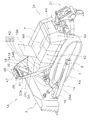
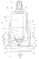
- It is a perspective view of the support member concerning a 1st embodiment.
- FIG. 1 It is a perspective view which shows the structure around the supporting member and lift cylinder which concern on 1st Embodiment. It is sectional drawing of the supporting member and lift cylinder which concern on 1st Embodiment. It is a perspective view of a joint main part. It is a perspective view which shows the actual condition of a work vehicle. It is a figure which shows an example of the image imaged by the surrounding imaging part mounted in the working vehicle shown in FIG. It is a figure which shows an example of a surrounding synthetic
- FIG. 1 is a perspective view of a work vehicle 1 according to the first embodiment.
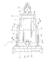
- FIG. 2 is a side view of the work vehicle 1 according to the first embodiment.
- FIG. 3 is a plan view of the work vehicle 1 according to the first embodiment.
- the work vehicle 1 is a bulldozer.
- the work vehicle 1 is a vehicle that does not include a cab. As will be described later, the work vehicle 1 can be remotely operated.
- the work vehicle 1 includes a vehicle main body 2 and a work implement 3.
- the vehicle body 2 includes a traveling device 4 and an engine room 5.
- the traveling device 4 is a device for causing the work vehicle 1 to travel.
- the traveling device 4 has crawler belts 4a and 4b.
- the crawler belt 4 a is provided on the left side of the vehicle body 2.
- the crawler belt 4 b is provided on the right side portion of the vehicle main body 2.
- the work vehicle 1 travels by driving the crawler belts 4a and 4b.
- the front means the direction where the lift cylinder is arrange
- back means the opposite direction.
- left and right shall mean the right and left direction in the state which faced the above-mentioned front.
- the engine room 5 is arranged on the front part of the vehicle body 2.
- An engine 11 (see FIG. 4) is disposed in the engine chamber 5.
- the vehicle main body 2 has a rear housing portion 6, a right housing portion 7, and a left housing portion 8.
- the engine room 5, the rear housing part 6, the right housing part 7, and the left housing part 8 are arranged so as to surround the maintenance area MA.
- the engine room 5 is disposed in front of the maintenance area MA.
- the rear housing portion 6 is disposed behind the maintenance area MA.
- the right accommodating portion 7 is disposed on the right side of the maintenance area MA.
- the left accommodating portion 8 is disposed on the left side of the maintenance area MA.
- the rear container 6 is a fuel tank.
- a configuration may be employed in which the fuel tank is accommodated in the rear accommodating portion 6.
- a cooling device such as a radiator is disposed in the right accommodating portion 7.
- a hydraulic oil tank is disposed in the left accommodating portion 8.
- the thing accommodated in each accommodating part 6-8 is not restricted to these things, You may change.
- the lid member 10 is disposed above the maintenance area MA.
- the lid member 10 is disposed so that the maintenance area MA can be opened and closed.
- 1 illustrates a state where the lid member 10 is opened
- FIGS. 2 and 3 illustrate a state where the lid member 10 is closed.
- the engine room 5 and the accommodating part 7 are provided with doors (not shown) for opening and closing the engine room 5 and the accommodating part 7 facing the maintenance area MA.
- the operator can access the engine room 5 and the inside of the storage part 7 from the maintenance area MA by opening the doors of the engine room 5 and the storage part 7.
- the work machine 3 is disposed in front of the vehicle body 2.
- the work machine 3 is disposed in front of the engine room 5.
- the work machine 3 is a blade.
- the work machine 3 is supported by the left arm 14 and the right arm 15.
- the left arm 14 is attached to the left side of the vehicle body 2.
- the right arm 15 is attached to the right side of the vehicle body 2.
- the work machine 3 is provided with a left tilt cylinder 16, a right tilt cylinder 17, and a lift cylinder 18.
- the left tilt cylinder 16 is attached to the left side of the vehicle body 2.
- the right tilt cylinder 17 is attached to the left side of the vehicle body 2.
- the left tilt cylinder 16 and the right tilt cylinder 17 are driven by hydraulic oil from the hydraulic pump 12.
- the left tilt cylinder 16 and the right tilt cylinder 17 operate the working machine 3 to the left and right.
- the lift cylinder 18 is attached to the center of the vehicle body 2 in the vehicle width direction.
- the lift cylinder 18 is attached to the vehicle main body 2 while being inclined in the front-rear direction of the vehicle main body 2.
- only one lift cylinder 18 is provided.
- the lift cylinder 18 is disposed in front of the engine compartment 5.
- the lift cylinder 18 is disposed behind the work machine 3.
- the lift cylinder 18 is driven by hydraulic oil from the hydraulic pump 12.
- the lift cylinder 18 moves the work machine 3 up and down.
- Work vehicle 1 includes a ripper device 31.
- the ripper device 31 is disposed behind the vehicle body 2.
- the ripper device 31 is attached to the vehicle body 2. Note that the ripper device may be omitted.
- FIG. 4 is a block diagram showing a control system of the work vehicle 1.
- the work vehicle 1 includes a hydraulic pump 12 and a pump capacity control unit 19.
- the hydraulic pump 12 discharges hydraulic oil by being driven by the engine 11.
- the hydraulic pump 12 is a variable displacement pump, and the pump displacement control unit 19 controls the discharge displacement of the hydraulic pump 12.
- the work vehicle 1 has a work implement control valve 20 and a hydraulic actuator 21.
- the hydraulic actuator 21 is driven by the hydraulic oil discharged from the hydraulic pump 12.
- the hydraulic actuator 21 includes the lift cylinder 18 and the left and right tilt cylinders 16 and 17 described above.
- the work machine control valve 20 controls supply and discharge of hydraulic oil to the hydraulic actuator 21.
- the work vehicle 1 has a power transmission device 13 and a clutch control valve 22.
- the power transmission device 13 includes, for example, a transmission and a torque converter.
- the clutch control valve 22 controls switching of a shift clutch, a forward / reverse clutch, a steering clutch, and the like included in the power transmission device 13.
- Work vehicle 1 has an imaging unit 23.
- the imaging unit 23 acquires an image around the work vehicle 1. The imaging unit will be described in detail later.
- Work vehicle 1 includes a vehicle control unit 24 and a communication unit 25.
- the communication unit 25 is connected to an antenna 99 (see FIG. 1) mounted on the vehicle body 2.
- the communication unit 25 communicates with the communication unit 27 of the remote operation device 26 by radio.
- the remote control device 26 is disposed in a management center remote from the work site where the work vehicle 1 is used.
- the remote control device 26 may be portable and may be arranged at a work site.
- the vehicle control unit 24 includes an arithmetic device such as a CPU, a memory such as a RAM or a ROM, or a storage device such as a hard disk.
- the vehicle control unit 24 is programmed to control the work vehicle 1 based on an operation signal from the remote operation device 26. Further, the vehicle control unit 24 acquires the image data acquired by the imaging unit 23 via wired or wireless. The vehicle control unit 24 transmits the image data captured by the imaging unit 23 to the communication unit 27 of the remote operation device 26 via the communication unit 25.
- the remote operation device 26 includes a remote control unit 28 and an operation unit 29.
- the remote control unit 28 includes an arithmetic device such as a CPU, a memory such as a RAM or a ROM, or a storage device such as a hard disk.
- the operation unit 29 is operated by an operator who drives the work vehicle 1.
- the operation unit 29 includes an accelerator operation device for adjusting the output of the engine 11.
- the operation unit 29 includes a work machine operation device for operating the work machine 3.
- the operation unit 29 includes a steering operation device for changing the traveling direction of the work vehicle 1 to the left and right.
- the remote control unit 28 transmits an operation signal indicating the operation content by the operation unit 29 to the communication unit 25 of the work vehicle 1 via the communication unit 27.
- the remote operation device 26 has a display unit 30.
- the display unit 30 is configured by a display such as a CRT, LCD, or OELD, for example.
- the display unit 30 is not limited to these displays, and may be other types of displays.
- the communication unit 27 of the remote operation device 26 receives the image data captured by the imaging unit 23 from the communication unit 25 of the work vehicle 1.
- the remote control unit 28 is programmed to generate a display image indicating the periphery of the work vehicle 1 based on the image data captured by the imaging unit 23 and display the display image on the display unit 30.
- the operator operates the operation unit 29 while viewing the display image. Thereby, an operation signal is transmitted from the communication unit 27 of the remote operation device 26, and the communication unit 25 of the work vehicle 1 receives the operation signal from the remote operation device 26.
- the vehicle control unit 24 controls the engine 11, the pump capacity control unit 19, the work implement control valve 20, the clutch control valve 22, and the like described above based on the operation signal. Thereby, the operator can operate the work vehicle 1 remotely.
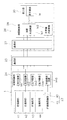
- FIG. 5 is a block diagram illustrating a configuration and a processing flow for generating a display image.
- the imaging unit 23 mounted on the work vehicle 1 includes a surrounding imaging unit 40 and a work implement imaging unit 45.
- the surrounding imaging unit 40 images a region around the vehicle body 2. That is, the surrounding imaging unit 40 images the front, rear, left, and right areas of the vehicle body 2.
- the work machine imaging unit 45 images the area in front of the work machine 3 and the work machine 3.
- the surrounding imaging unit 40 includes a front imaging unit 41, a left imaging unit 42, a right imaging unit 43, and a rear imaging unit 44.
- a camera equipped with a fisheye lens can be employed as the front imaging unit 41, the left imaging unit 42, the right imaging unit 43, and the rear imaging unit 44.
- the front imaging unit 41 is attached to the support member 33.
- the front imaging unit 41 is disposed in front of the lift cylinder 18.
- the front imaging unit 41 images the front of the vehicle body 2.
- the left imaging unit 42 is attached to the left side of the vehicle body 2.
- the left imaging unit 42 images the left side of the vehicle body 2.
- the right imaging unit 43 is attached to the right side of the vehicle body 2.
- the right imaging unit 43 images the right side of the vehicle body 2.
- the rear imaging unit 44 is attached to the rear part of the vehicle body 2.
- the rear imaging unit 44 images the rear of the vehicle body 2.
- the work machine imaging unit 45 is a camera having a lens with a normal angle of view.
- the work machine imaging unit 45 is disposed above the work machine 3.
- the work implement imaging unit 45 is disposed above the upper end of the work implement 3.
- the work machine imaging unit 45 is disposed above the front imaging unit 41.
- the work machine imaging unit 45 is disposed in front of the front imaging unit 41.
- the work machine imaging unit 45 is supported by the support member 33.
- the front imaging unit 41 and the work machine imaging unit 45 are attached to the support member 33.
- the support member 33 is attached to the front portion of the vehicle body 2.
- the support member 33 is attached to the center of the vehicle body 2 in the vehicle width direction.
- the support member 33 is formed of a bent sheet metal.
- the support member 33 includes a column part 34 and a flange part 35.
- the column part 34 extends upward from the vehicle body 2.
- the column part 34 has a tapered shape toward the upper side.
- the column portion 34 is disposed in front of the engine compartment 5.
- the column part 34 is disposed behind the work machine 3.
- the front imaging unit 41 is attached to the column part 34.
- the front imaging unit 41 is attached to the front surface of the column part 34.
- the collar portion 35 extends forward from the column portion 34.
- the collar portion 35 is located above the work machine 3.
- the collar portion 35 has a tapered shape toward the front.
- the collar unit 35 supports the work machine imaging unit 45.
- the work machine imaging unit 45 is attached to the tip of the collar unit 35. Specifically, the work machine imaging unit 45 is attached to the lower surface of the distal end portion of the flange portion 35.
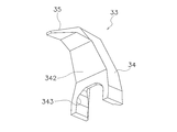
- FIG. 6 and 7 are perspective views of the support member 33.
- a through portion 341 is formed on the back surface of the column portion 34.
- the penetration part 341 has a shape that is recessed forward.
- the penetrating part 341 extends in the vertical direction and penetrates the support member 33 in the vertical direction.
- the front surface 342 of the pillar portion 34 is inclined forward and upward from the vehicle body 2.
- a recess 343 is formed in the lower part of the front surface 342 of the column part 34.
- the recess 343 has a shape that is recessed upward.
- the penetrating part 341 communicates with the concave part 343.
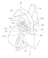
- FIG. 8 and 9 are perspective views of the support member 33 and the lift cylinder 18.
- FIG. 10 is a cross-sectional view of the support member 33.
- the lift cylinder 18 is disposed in the penetrating portion 341. For this reason, as shown in FIG. 2, the lift cylinder 18 overlaps the column part 34 in the vehicle side view.
- the lift cylinder 18 passes through the penetrating part 341 and protrudes upward from the support member 33.
- the lift cylinder 18 passes through the penetration part 341 and protrudes downward from the support member 33.
- the vehicle body 2 includes a mount member 36 and a universal joint 37.
- the mount member 36 is disposed in front of the engine compartment 5.
- the mount member 36 is connected to a vehicle body frame (not shown) in the vehicle main body 2.
- the lift cylinder 18 is attached to the mount member 36 via a universal joint 37.
- the column portion 34 of the support member 33 is attached to the mount member 36.
- the column portion 34 is disposed on the mount member 36.
- the bottom of the pillar 34 is attached to the mount member 36.
- the universal joint 37 supports the lift cylinder 18 so as to be turnable in the front-rear and left-right directions.
- the universal joint 37 is disposed in the recess 343.
- the universal joint 37 includes a joint main body 51, a left shaft support portion 52, a right shaft support portion 53, a front shaft support portion 54, and a rear shaft support portion 55.
- FIG. 11 is a perspective view of the joint body 51.
- the joint body 51 has an opening 511.
- the opening 511 penetrates the joint main body 51 in the vertical direction.
- the lift cylinder 18 is passed through the opening 511.
- the joint body 51 has a left rotation shaft portion 512 and a right rotation shaft portion 513.
- the left rotation shaft portion 512 and the right rotation shaft portion 513 are arranged with an interval in the vehicle width direction.
- An opening 511 is disposed between the left rotation shaft portion 512 and the right rotation shaft portion 513.
- the left rotation shaft portion 512 and the right rotation shaft portion 513 extend in the vehicle width direction.
- the left rotation shaft portion 512 is rotatably supported by the left shaft support portion 52.
- the right rotation shaft portion 513 is rotatably supported by the right shaft support portion 53.
- the lift cylinder 18 is supported by the universal joint 37 so as to be pivotable back and forth.
- the joint body 51 has a front mounting portion 514 and a rear mounting portion 515.
- the front mounting portion 514 and the rear mounting portion 515 are arranged with a space in the front-rear direction.
- An opening 511 is disposed between the front mounting portion 514 and the rear mounting portion 515.
- a front shaft support portion 54 is attached to the front attachment portion 514.
- the front shaft support portion 54 rotatably supports a front rotation shaft portion 181 provided in the lift cylinder 18.
- the front rotating shaft 181 protrudes forward from the lift cylinder 18.
- a rear shaft support portion 55 is attached to the rear attachment portion 515.
- the rear shaft support portion 55 rotatably supports a rear rotation shaft portion 182 provided in the lift cylinder 18.
- the rear rotating shaft portion 182 protrudes rearward from the lift cylinder 18.
- the lift cylinder 18 is supported by the universal joint 37 so as to be rotatable left and right.
- the vehicle control unit 24 acquires image data around the vehicle body 2 from the surrounding imaging unit 40. That is, as shown in FIG. 5, the vehicle control unit 24 includes a front image Im1, a left image Im2, and a left imaging unit 42, a left imaging unit 42, a right imaging unit 43, and a rear imaging unit 44. The right image Im3 and the rear image Im4 are acquired.
- the front image Im1 is an image in front of the vehicle body 2.
- the left image Im ⁇ b> 2 is a left image of the vehicle body 2.
- the right image Im3 is a right image of the vehicle body 2.
- the rear image Im4 is an image behind the vehicle body 2.
- the vehicle control unit 24 acquires the image data of the area in front of the work machine 3 from the work machine imaging unit 45. That is, the vehicle control unit 24 acquires the pre-work machine image Im5 from the work machine imaging unit 45.
- the work implement front image Im5 is an image in front of the work implement 3 including the work implement 3.
- the vehicle control unit 24 sends the front image Im1, the left image Im2, the right image Im3, the rear image Im4, and the work implement front image Im5 to the remote control unit 28 via the communication unit 25.
- the remote control unit 28 generates a surrounding composite image Is1 from the images Im1-Im4 captured by the surrounding imaging unit 40.
- the surrounding composite image Is1 is an image showing the surroundings of the work vehicle 1 in a bird's-eye view, and is combined with the vehicle model M1.
- the vehicle model M1 is a model that indicates the shape of the work vehicle 1.
- the remote control unit 28 generates a work implement composite image Is2 from the work implement pre-image Im5 captured by the work implement image capture unit 45.
- the work implement composite image Is2 is an image showing a region in front of the work implement 3, and is combined with the vehicle model M1 and the surrounding composite image Is1.
- FIG. 12 is a perspective view showing an actual situation of the work vehicle 1.
- FIG. 13 shows an example of an image taken by the surrounding imaging unit 40 mounted on the work vehicle 1 in the state shown in FIG. Specifically, FIG. 13A is a front image Im1 captured by the front imaging unit 41.
- FIG. 13B is a left image Im ⁇ b> 2 captured by the left imaging unit 42.
- FIG. 13C is a right image Im3 captured by the right imaging unit 43.
- FIG. 13D is a rear image Im4 captured by the rear imaging unit 44.
- the remote control unit 28 generates the surrounding composite image Is1 by projecting the image acquired from the surrounding imaging unit 40 onto the first projection plane A1.
- FIG. 14 shows an example of the surrounding composite image Is1 generated by the remote control unit 28.
- the first projection plane A1 has a hemispherical curved surface A11 surrounding the vehicle model M1 and a plane A12 corresponding to the ground surface.
- the vehicle model M1 is disposed on the plane A12.
- the first projection plane A1 has a mesh structure, and the remote control unit 28 projects the image acquired from the surrounding imaging unit 40 onto the first projection plane A1 by texture mapping. Thus, the surrounding composite image Is1 is generated.
- the front image Im1, the left image Im2, the right image Im3, and the rear image Im4 are projected on the first projection plane A1 as a surrounding composite image Is1 of the vehicle model M1. It is synthesized. However, since the rear image (see FIG. 13A) of the work machine 3 is reflected in the front image Im1, a part of the front of the work machine 3 including the front surface of the work machine 3 becomes a blind spot. Therefore, as shown in FIG. 14, the image Imw in front of the work implement 3 (the hatched portion in FIG. 14) is missing or not displayed accurately only with the surrounding image Is1.
- FIG. 15 is a diagram illustrating an example of the pre-worker image Im5 captured by the work implement imaging unit 45.
- the pre-work machine image Im ⁇ b> 5 includes an image Ima that shows the front surface of the work machine 3 and an image Imb that shows the ground surface located in front of the work machine 3.
- the work implement pre-image Im ⁇ b> 5 is as shown in FIG. 15.
- An image Imx showing the work object X is included.
- the remote control unit 28 projects the work implement pre-image Im5 captured by the work implement imaging unit 45 onto the second projection plane A2, thereby generating the work implement composite image Is2.
- the second projection plane A2 is disposed on the front surface of the work machine 3 of the vehicle model M1 and the ground surface positioned in front of the work machine 3 of the vehicle model M1.
- the display unit 30 displays the display image Is.
- FIG. 18 is a diagram illustrating an example of the display image Is. As shown in FIG. 18, the display image Is is three-dimensionally represented so that the work vehicle 1 and its surroundings can be seen from diagonally forward.
- the display image Is includes the vehicle model M1, the surrounding composite image Is1, and the work implement composite image Is2 generated as described above.
- the situation around the work vehicle 1 imaged by the surrounding imaging unit 40 is displayed as the surrounding composite image Is1 around the vehicle model M1.
- the situation in front of the work machine 3 imaged by the work machine imaging unit 45 is displayed as a work machine composite image Is2 on the front surface of the work machine 3 of the vehicle model M1 and the ground surface below the work machine 3.
- the display image Is is updated in real time and displayed as a moving image.
- the situation around the work vehicle 1 can be easily grasped from the display image Is.
- the work machine imaging unit 45 attached to the collar part 35 of the support member 33 can image a region in front of the work machine 3 that becomes a blind spot only with the surrounding imaging unit 40. Thereby, the state of the area
- the lift cylinder 18 is attached to the center of the vehicle body 2 in the vehicle width direction. Thereby, compared with the case where a pair of left and right lift cylinders are arranged apart from each other in the left and right, it is possible to reduce the load caused by the twist transmitted from the work implement 3 to the vehicle main body 2.
- the operator of the work vehicle 1 can grasp the situation in front of the work machine 3 from the display image Is. For this reason, even if the lift cylinder 18 is attached to the center of the vehicle body 2 in the vehicle width direction, a decrease in forward visibility is not a problem.
- the lift cylinder 18 is disposed in the penetrating portion 341 of the support member 33. Therefore, interference between the lift cylinder 18 and the support member 33 can be avoided, and the support member 33 and the lift cylinder 18 can be arranged in a compact manner.
- the column part 34 is attached to the mount member 36. For this reason, the support member 33 can be firmly supported. Further, the support member 33 and the lift cylinder 18 can be arranged in a compact manner. In particular, the lift cylinder 18 is disposed in the penetrating portion 341 of the column portion 34, and the column portion 34 and the lift cylinder 18 overlap in a vehicle side view. For this reason, the support member 33 and the lift cylinder 18 can be arrange
- the lift cylinder 18 is attached to the mount member 36 via a universal joint 37. For this reason, the load transmitted from the lift cylinder 18 to the vehicle main body 2 can be further reduced by rotating the lift cylinder 18 back and forth and right and left.
- the front surface 342 of the column part 34 is inclined forward and upward from the vehicle body 2. For this reason, the movable range of the working machine 3 arranged in front of the column part 34 can be expanded. Thereby, the amount of soil which can be carried by the working machine 3 at the time of excavation can be increased.
- the collar part 35 has a tapered shape toward the front. Thereby, the load to the attachment part to the vehicle main body 2 of the support member 33 can be reduced. In other words, the flange 35 has a shape that becomes thicker toward the rear. For this reason, the work implement imaging unit 45 can be firmly supported, and the vibration of the work implement imaging unit 45 can be suppressed small.
- FIG. 19 is a perspective view of the work vehicle 1 according to the second embodiment.
- FIG. 20 is a side view of the work vehicle 1 according to the second embodiment.
- FIG. 21 is a plan view of a work vehicle 1A according to the second embodiment.
- the same components as those in the first embodiment are denoted by the same reference numerals, and detailed description thereof is omitted.
- the work vehicle 1A is a bulldozer.
- the work vehicle 1A is a vehicle that does not include a driver's cab.
- the work vehicle 1A can be operated remotely.
- the work vehicle 1 ⁇ / b> A includes a vehicle body 2 ⁇ / b> A and a work machine 3.
- the vehicle main body 2A has an engine room 5A instead of the engine room 5 of the first embodiment.
- the engine room 5A differs from the engine room 5 according to the first embodiment in the shape of the exterior member 60 that covers the engine room 5A. In the top view, the length of the exterior member 60 in the vehicle width direction becomes shorter toward the front.
- the exterior member 60 includes a center front part 61, a left side part 62, and a right side part 63.
- the center front part 61 is a wall part of the front end of the engine compartment 5A.
- the central front portion 61 corresponds to a central portion in the vehicle width direction of the vehicle main body 2A to which the lift cylinder 18 is attached.
- the left side portion 62 is also located rearward and on the left side of the central front portion 61.
- the left side portion 62 is, for example, a left side wall that extends rearward and leftward from the central front portion 61 in a top view.
- the central front portion 61 is also located rearward and on the right side.
- the right side portion 63 is, for example, a right side wall that extends rearward and rightward from the central front portion 61 in a top view.
- the engine chamber 5A is the same as the engine chamber 5 of the first embodiment in other points.
- the vehicle body 2A includes a rear housing portion 6A, a right housing portion 7, and a left housing portion 8.
- the engine compartment 5A, the rear housing portion 6A, the right housing portion 7, and the left housing portion 8 are arranged so as to surround the maintenance area MA.
- the engine room 5A is disposed in front of the maintenance area MA.
- the rear housing portion 6A is disposed behind the maintenance area MA.
- the rear container 6A is a fuel tank or a structure in which the fuel tank is accommodated.
- the rear housing portion 6A protrudes rearward compared to the rear housing portion 6 according to the first embodiment.
- the lid member 10A is disposed above the maintenance area MA. 10 A of cover members are arrange
- FIG. 1 illustrates a state where the lid member 10A is opened
- FIGS. 2 and 3 illustrate a state where the lid member 10A is closed.
- the lid member 10A is different from the lid member 10 of the first embodiment in that it opens upward and forward.
- the work vehicle 1A further includes a headlamp 46 and a rotating lamp 47.
- the headlamp 46, the rotating lamp 47, the front imaging unit 41, and the work implement imaging unit 45 are attached to the support member 33A.
- 33 A of supporting members are attached to the front part of 2 A of vehicle main bodies. Specifically, the support member 33 ⁇ / b> A is attached to the left side portion 62 and the right side portion 63.
- the support member 33A is formed of a plate-like member.
- the support member 33A includes a left column portion 34L, a right column portion 34R, a first beam portion 38, and a second beam portion 39.
- the left column portion 34L and the right column portion 34R are collectively referred to as a column portion 34A.
- the left column part 34L and the right column part 34R are symmetrical.
- the left column portion 34L extends upward and forward from the left side portion 62.
- the right column portion 34R extends upward and forward from the right side portion 63. That is, the column portion 34A extends upward from the vehicle body 2A.
- the front surface 342A of the left column portion 34L is inclined forward and upward from the vehicle body 2A.
- the front surface of the right column portion 34R is inclined forward and upward from the vehicle body 2A. That is, the front surface of the column portion 34A is inclined forward and upward from the vehicle body 2A.
- the lift cylinder 18 overlaps the left column part 34L. Although not shown, the lift cylinder 18 overlaps the right column portion 34R in the vehicle side view. That is, in the vehicle side view, the lift cylinder 18 overlaps the column portion 34A. When viewed from the side of the vehicle, the lift cylinder 18 overlaps the support member 33A.
- the left column portion 34L extends in the right direction (the direction toward the vehicle width direction center of the vehicle main body 2A) as it goes forward.
- the right column portion 34R extends to the left (in the direction toward the center in the vehicle width direction of the vehicle main body 2A) as it goes forward. That is, the column portion 34A extends toward the center in the vehicle width direction of the vehicle main body 2A as it goes forward.
- the left column portion 34L and the right column portion 34R are bent toward the center in the vehicle width direction of the first beam portion 38 at the connection portion with the first beam portion 38. That is, the column portion 34 ⁇ / b> A is bent toward the center in the vehicle width direction of the first beam portion 38 at the connection portion with the first beam portion 38.
- the left column portion 34L and the right column portion 34R have a shape that tapers upward. That is, the column portion 34A has a shape that tapers upward.
- the left column portion 34L and the right column portion 34R are arranged on the front side of the engine room 5A. That is, the column portion 34A is disposed on the front side of the engine room 5A.
- the left column portion 34L and the right column portion 34R are disposed behind the work implement 3. That is, the column portion 34 ⁇ / b> A is disposed behind the work machine 3.
- the first beam portion 38 is connected to the left column portion 34L and the right column portion 34R, and extends inward in the vehicle width direction from the left column portion 34L and the right column portion 34R. That is, the first beam portion 38 extends from the column portion 34A in the vehicle width direction.
- the support member 33 ⁇ / b> A forms a penetrating portion 341 ⁇ / b> A by the left column portion 34 ⁇ / b> L, the right column portion 34 ⁇ / b> R, and the first beam portion 38.
- the lift cylinder 18 is disposed through the penetrating portion 341A.
- the first beam portion 38 is located above the work machine 3.
- the first beam portion 38 supports the front imaging unit 41, the work machine imaging unit 45, and the headlamp 46.
- FIG. 22 is an enlarged perspective view near the upper end of the support member 33A according to the second embodiment. In FIG. 22, the illustration of the engine chamber 5A behind the support member 33A is omitted.
- the front imaging unit 41 and the work machine imaging unit 45 are arranged side by side at the center of the first beam unit 38 in the vehicle width direction. Specifically, the work machine imaging unit 45 is disposed immediately above the first beam unit 38, and the front imaging unit 41 is disposed immediately above the work machine imaging unit 45.
- the front imaging unit 41 may employ a camera equipped with a lens having a normal angle of view, but may be a camera equipped with a fisheye lens.
- the optical axis of the front imaging unit 41 is slightly below the front.
- the work machine imaging unit 45 is a camera including a lens having a normal angle of view.
- the optical axis of the work machine imaging unit 45 is directed downward from the optical axis of the front imaging unit 41.
- Both the work machine imaging unit 45 and the front imaging unit 41 are disposed in front of the lift cylinder 18.
- a headlamp 46 is disposed on the side of the front imaging unit 41 and the work machine imaging unit 45.
- the three headlamps 46 are arranged on the left and right sides of the front imaging unit 41 and the work machine imaging unit 45, respectively, but are not limited thereto.
- the second beam portion 39 is connected to the upper ends of the left column portion 34L and the right column portion 34R. That is, the second beam portion 39 is connected to the upper end of the column portion 34A.
- the second beam portion 39 extends inward in the vehicle width direction from the upper ends of the left column portion 34L and the right column portion 34R above the first beam portion 38. That is, the second beam portion 39 extends in the vehicle width direction from the upper end of the column portion 34A above the first beam portion 38.
- the second beam portion 39 supports the rotating lamp 47.
- the rotating lamp 47 is disposed on the second beam portion 39. Therefore, as indicated by a two-dot chain line in FIG. 20, the upper end of the rotating lamp 47 is located above the upper end of the lift cylinder 18. For this reason, the rotating lamp 47 is not blocked by the lift cylinder 18. Therefore, the visibility of the rotating lamp 47 is improved.
- the lift cylinder 18 is supported by the same mount member 36 and universal joint 37 as in the first embodiment. Therefore, the lift cylinder 18 is attached to the center of the vehicle body 2 in the vehicle width direction. The lift cylinder 18 is attached to the vehicle main body 2 while being inclined in the front-rear direction of the vehicle main body 2.
- control system of the work vehicle 1A in the second embodiment the configuration and processing for generating a display image are the same as those in the first embodiment.
- the work vehicle 1A according to the second embodiment described above also has the same effects as the work vehicle 1 according to the first embodiment. That is, even in the work vehicle 1A, the situation around the work vehicle 1A can be easily grasped from the display image Is.
- the work machine imaging unit 45 attached to the first beam portion 38 of the support member 33 ⁇ / b> A can image a region in front of the work machine 3 that becomes a blind spot only with the surrounding imaging unit 40.
- the lift cylinder 18 is attached to the center of the vehicle body 2A in the vehicle width direction. Therefore, compared with the case where a pair of left and right lift cylinders are arranged apart from each other on the left and right, it is possible to reduce the load caused by the twist transmitted from work implement 3 to vehicle body 2A.
- the operator of the work vehicle 1A can grasp the situation ahead of the work machine 3 from the display image Is. Therefore, even if the lift cylinder 18 is attached to the center portion in the vehicle width direction of the vehicle main body 2A, the decrease in forward visibility is not a problem.
- the lift cylinder 18 is disposed in the penetrating portion 341A of the support member 33A. Therefore, interference with the support member 33A of the lift cylinder 18 is avoided.
- the front surface of the column part 34A is inclined forward and upward from the vehicle body 2A. For this reason, the movable range of the working machine 3 arranged in front of the column part 34A can be expanded. Thereby, the amount of soil which can be carried by the working machine 3 at the time of excavation can be increased.
- the column part 34A has a shape that tapers upward. Thereby, the load to the attachment part of 2 A of vehicle main bodies of 33 A of support members can be reduced. In other words, the column portion 34A has a shape that becomes thicker downward. For this reason, the front imaging unit 41 and the work implement imaging unit 45 can be firmly supported, and vibrations of the front imaging unit 41 and the work implement imaging unit 45 can be suppressed to be small.
- the work vehicle is not limited to a bulldozer, but may be another type of work vehicle such as a wheel loader.
- the work vehicle is not limited to a remotely operated vehicle.
- a cab is provided in the vehicle main body 2, and a device similar to the remote control device 26 may be arranged in the cab.
- the operator can easily operate the work vehicle while viewing the display image.
- the display image generation method is not limited to the method of the above embodiment, and may be changed.
- the shapes of the first projection plane A1 and the second projection plane A2 may be changed.
- the number of imaging units of the surrounding imaging unit 40 is not limited to four, but may be three or less, or five or more.
- the arrangement of the imaging units of the surrounding imaging unit 40 is not limited to the arrangement of the above-described embodiment, and may be a different arrangement.
- Each imaging unit of the surrounding imaging unit 40 is not limited to a camera equipped with a fisheye lens, but may be another type of imaging device.
- the front imaging unit 41 is not limited to the support member 33 and may be attached to other parts. For example, the front imaging unit 41 may be attached to the vehicle body 2.
- the number of work implement imaging units 45 is not limited to one, and may be two or more.
- the arrangement of the work machine imaging unit 45 is not limited to the arrangement of the above embodiment, and may be a different arrangement.
- the structure of the support members 33 and 33A is not limited to the structure of the above embodiment, and may be changed.
- the column portion 34 may be attached to a portion other than the mount member 36.
- the left column portion 34L and the right column portion 34R may be attached not to the side wall of the engine compartment 5A but to a more inside position.
- the lift cylinder 18 may be attached to the mount member 36 without using the universal joint 37.
- the shapes of the pillar 34, the left pillar 34L, and the right pillar 34R may be changed.
- the shape of the collar part 35, the 1st beam part 38, and the 2nd beam part 39 may be changed.
- the work implement 3 may be removed from the work vehicle 1. Further, the ripper device 31 (see FIG. 2) may be removed from the work vehicle 1. Similarly, as shown in FIG. 24, the work implement 3 (see FIG. 20) may be removed from the work vehicle 1A. Further, the ripper device 31 (see FIG. 20) may be removed from the work vehicle 1A.
- the present invention it is possible to provide a work vehicle that can easily grasp the state of the area in front of the work vehicle and improve the balance of the load transmitted from the work machine to the vehicle body.
Landscapes
- Engineering & Computer Science (AREA)
- Mechanical Engineering (AREA)
- Mining & Mineral Resources (AREA)
- Civil Engineering (AREA)
- General Engineering & Computer Science (AREA)
- Structural Engineering (AREA)
- Component Parts Of Construction Machinery (AREA)
Abstract
リフトシリンダは、車両本体の車幅方向における中央部に取り付けられる。リフトシリンダは、作業機を上下に動作させる。支持部材は、車両本体の車幅方向における中央部に取り付けられ、車両本体から上方に向かって延びる。撮像部は、支持部材に支持され、車両本体の前方の領域を撮像する。支持部材には、貫通部が形成されている。リフトシリンダは、貫通部を通して配置される。
Description
本発明は、作業車両に関する。
作業車両は、作業機を駆動するためのアクチュエータを備えている。例えば、作業機を上下に動作させるための左右一対のリフトシリンダが車体の両側部に取り付けられる(特許文献1)。
しかし、作業機を用いて掘削等の作業が行われる場合、作業機に加わる負荷は、リフトシリンダを介して作業車両の車体に伝わる。このとき、一対のリフトシリンダが左右に離れて配置されていると、それぞれのリフトシリンダから異なる大きさ負荷が車体に加わる可能性がある。
負荷バランス改善のため、作業車両の中央にリフトシリンダを配置することも可能である。しかし、この場合、リフトシリンダによって作業車両の前方の領域を把握しにくくなる。
本発明の課題は、作業車両の前方の領域の状況を容易に把握することができると共に、作業機から車体に伝わる負荷のバランスを改善することができる作業車両を提供することにある。
本発明の第1の態様に係る作業車両は、車両本体と、作業機と、リフトシリンダと、撮像部と、支持部材と、を備える。作業機は、車両本体の前方に設けられる。リフトシリンダは、車両本体の車幅方向における中央部に取り付けられる。リフトシリンダは、作業機を上下に動作させる。支持部材は、車両本体の車幅方向における中央部に取り付けられ、車両本体から上方に向かって延びる。撮像部は、支持部材に支持され、車両本体の前方の領域を撮像する。支持部材には、貫通部が形成されている。リフトシリンダは、貫通部を通して配置される。
第1の態様に係る作業車両では、撮像部によって、車両本体の前方の領域を撮像することができる。これにより、車両本体の前方の領域の状況を容易に把握することができる。また、リフトシリンダは、車両本体の車幅方向における中央部に取り付けられる。これにより、一対のリフトシリンダが左右に離れて配置される場合と比べて、作業機から車体に伝わる負荷のバランスを改善することができる。
また、作業車両のオペレータは、撮像部によって撮像された画像によって作業車両の前方の状況を把握することができる。そのため、リフトシリンダ及び支持部材が車両本体の車幅方向における中央部に取り付けられても、前方視界性の低下は問題とならない。さらに、リフトシリンダは、支持部材の貫通部に配置される。そのため、リフトシリンダの支持部材への干渉を回避すると共に、支持部材とリフトシリンダとをコンパクトに配置することができる。
車両本体は、マウント部材を有してもよい。マウント部材にはリフトシリンダが取り付けられてもよい。支持部材は、マウント部材に取り付けられてもよい。この場合、支持部材とリフトシリンダとをコンパクトに配置することができる。また、支持部材を強固に支持することができる。
車両本体は、リフトシリンダを前後左右に回動可能に支持する自在継手を有してもよい。支持部材は、自在継手を介してマウント部材に取り付けられてもよい。この場合、リフトシリンダの動きが自在継手によって吸収される。これにより、リフトシリンダから車両本体に伝わる負荷をさらに軽減することができる。
支持部材は、車両本体から上方に向かって延びる柱部と、柱部から前方に延びる桿部と、を有してもよい。撮像部は、桿部に支持される作業機撮像部を有してもよい。この場合、作業機撮像部によって、作業機の前方の領域を撮像することで、作業機の前方の状況を容易に把握することができる。
本発明の第2の態様に係る作業車両は、車両本体と、作業機と、リフトシリンダと、撮像部と、支持部材と、を備える。作業機は、車両本体の前方に設けられる。リフトシリンダは、車両本体の車幅方向における中央部に取り付けられる。リフトシリンダは、作業機を上下に動作させる。支持部材は、車両本体の車幅方向における中央部に取り付けられ、車両本体から上方に向かって延びる。撮像部は、支持部材に支持され、車両本体の前方の領域を撮像する。支持部材には、貫通部が形成されている。リフトシリンダは、貫通部を通して配置される。
支持部材は、車両本体から上方に向かって延びる柱部と、柱部から車幅方向に延びる第1梁部と、を有する。柱部と前記第1梁部とによって貫通部が形成される。リフトシリンダは、貫通部を通して配置される。
第2の態様に係る作業車両でも、撮像部によって、車両本体の前方の領域を撮像することができる。これにより、車両本体の前方の領域の状況を容易に把握することができる。また、リフトシリンダは、車両本体の車幅方向における中央部に取り付けられる。これにより、一対のリフトシリンダが左右に離れて配置される場合と比べて、作業機から車体に伝わる負荷のバランスを改善することができる。
また、作業車両のオペレータは、撮像部によって撮像された画像によって作業車両の前方の状況を把握することができる。そのため、リフトシリンダが車両本体の車幅方向における中央部に取り付けられても、前方視界性の低下は問題とならない。さらに、リフトシリンダは、支持部材の貫通部に配置される。そのため、リフトシリンダの支持部材への干渉を回避される。
撮像部は、第1梁部に支持される作業機撮像部を有してもよい。この場合、作業機撮像部によって、作業機の前方の領域を撮像することで、作業機の前方の状況を容易に把握することができる。
第1の態様、第2の態様のいずれの作業車両においても、車両本体は、マウント部材を有してもよい。マウント部材にはリフトシリンダが取り付けられてもよい。第1の態様の作業車両においては、支持部材は、マウント部材に取り付けられてもよい。この場合、支持部材とリフトシリンダとをコンパクトに配置することができる。また、支持部材を強固に支持することができる。
第1の態様、第2の態様のいずれの作業車両においても、車両本体は、リフトシリンダを前後左右に回動可能に支持する自在継手を有してもよい。シフトシリンダは、自在継手を介してマウント部材に取り付けられてもよい。この場合、リフトシリンダの動きが自在継手によって吸収される。これにより、リフトシリンダから車両本体に伝わる負荷をさらに軽減することができる。
第1の態様、第2の態様のいずれの作業車両においても、柱部の前面は、車両本体から前方且つ上方に向かって傾斜していてもよい。この場合、柱部の前方に配置される作業機の可動範囲を拡大することができる。
第1の態様の作業車両においては、桿部は、前方に向かって先細りの形状を有してもよい。これにより、支持部材の車両本体への取付部分への負荷を軽減することができる。
第2の態様の作業車両においては、作業車両は、第1梁部に支持される前照灯をさらに備えるとよい。これにより、夜間や暗い場所での作業効率が向上する。
第2の態様の作業車両においては、作業車両は、回転灯をさらに備えるとよい。支持部材は、第1梁部の上方において、左柱部及び右柱部から車幅方向内方に延びる第2梁部をさらに有するとよい。回転灯は第2梁部に支持されるとよい。これにより、回転灯が高い位置に配置されるので、回転灯の視認性が向上する。
回転灯の上端は、リフトシリンダの上端よりも上方に位置するとよい。これにより、回転灯がリフトシリンダに遮られないので、回転灯の視認性が向上する。
第1の態様、第2の態様のいずれの作業車両においても、車両本体は、自在継手とマウント部材とを有してもよい。自在継手は、リフトシリンダを前後左右に回動可能に支持する。マウント部材は、自在継手を介してリフトシリンダが取り付けられる。この場合、リフトシリンダの動きが自在継手によって吸収される。これにより、リフトシリンダから車両本体に伝わる負荷をさらに軽減することができる。
第1の態様、第2の態様のいずれの作業車両においても、撮像部は、リフトシリンダの前方に配置される前撮像部を有してもよい。この場合、リフトシリンダの前方の領域の状況を容易に把握することができる。
第1の態様、第2の態様のいずれの作業車両においても、車両側面視において、リフトシリンダは、支持部材と重なってもよい。この場合、支持部材とリフトシリンダとをコンパクトに配置することができる。
第1の態様、第2の態様のいずれの作業車両においても、作業車両は、通信部と制御部とをさらに備えてもよい。通信部は、外部の遠隔操作装置と通信を行う。通信部は、撮像部が撮像した画像データを遠隔操作装置に送信する。通信部は、遠隔操作装置から作業車両を操作するための操作信号を受信する。制御部は、遠隔操作装置からの操作信号に基づいて作業車両の制御を行う。
この場合、作業車両のオペレータは、撮像部が撮像した画像を見ながら、遠隔操作装置によって遠隔から作業車両を操作することができる。
本発明によれば、作業車両の前方の領域の状況を容易に把握することができると共に、作業機から車体に伝わる負荷のバランスを改善することができる作業車両を提供することができる。
<第1実施形態>
以下、図面を参照して、実施形態に係る作業車両について説明する。図1は、第1実施形態に係る作業車両1の斜視図である。図2は、第1実施形態に係る作業車両1の側面図である。図3は、第1実施形態に係る作業車両1の平面図である。本実施形態において、作業車両1はブルドーザである。作業車両1は、運転室を備えていない車両である。後述するように、作業車両1は、遠隔から操作可能である。作業車両1は、車両本体2と作業機3とを有する。
以下、図面を参照して、実施形態に係る作業車両について説明する。図1は、第1実施形態に係る作業車両1の斜視図である。図2は、第1実施形態に係る作業車両1の側面図である。図3は、第1実施形態に係る作業車両1の平面図である。本実施形態において、作業車両1はブルドーザである。作業車両1は、運転室を備えていない車両である。後述するように、作業車両1は、遠隔から操作可能である。作業車両1は、車両本体2と作業機3とを有する。
車両本体2は、走行装置4とエンジン室5とを有する。走行装置4は、作業車両1を走行させるための装置である。走行装置4は、履帯4a,4bを有している。履帯4aは、車両本体2の左側部に設けられる。履帯4bは、車両本体2の右側部に設けられる。履帯4a,4bが駆動されることにより作業車両1が走行する。
なお、本実施形態において前方とは、車両本体2に対してリフトシリンダが配置されている方向を意味し、後方はその反対の方向を意味する。また、左右とは、前述の前方を向いた状態での左右の方向を意味するものとする。
エンジン室5は、車両本体2の前部上に配置されている。エンジン室5内には、エンジン11(図4参照)が配置されている。
車両本体2は、後収容部6と、右収容部7と、左収容部8とを有する。エンジン室5と、後収容部6と、右収容部7と、左収容部8とは、整備エリアMAの周囲を囲むように配置される。エンジン室5は、整備エリアMAの前方に配置されている。後収容部6は、整備エリアMAの後方に配置されている。右収容部7は、整備エリアMAの右方に配置されている。左収容部8は、整備エリアMAの左方に配置されている。
例えば、後収容部6は燃料タンクである。後収容部6に燃料タンクが収容される構成であってもよい。右収容部7には、ラジエータなどの冷却装置が配置される。左収容部8には、作動油タンクが配置される。ただし、各収容部6-8に収容される物はこれらの物に限らず、変更されてもよい。
整備エリアMAの上方には、蓋部材10が配置される。蓋部材10は、整備エリアMAを開閉可能に配置される。なお、図1では、蓋部材10が開かれている状態が図示されており、図2及び図3では、蓋部材10が閉じられている状態が図示されている。
エンジン室5、及び、収容部7には、整備エリアMAに面してエンジン室5、及び、収容部7を開閉するための扉(図示せず)が設けられている。作業者は、エンジン室5、及び、収容部7の扉を開くことによって整備エリアMAからエンジン室5、及び、収容部7の内部にアクセスすることができる。
作業機3は、車両本体2の前方に配置される。作業機3は、エンジン室5の前方に配置されている。本実施形態において、作業機3は、ブレードである。作業機3は、左アーム14及び右アーム15によって支持されている。左アーム14は、車両本体2の左側部に取り付けられている。右アーム15は、車両本体2の右側部に取り付けられている。
作業機3には、左チルトシリンダ16と、右チルトシリンダ17と、リフトシリンダ18とが取り付けられている。左チルトシリンダ16は、車両本体2の左側部に取り付けられている。右チルトシリンダ17は、車両本体2の左側部に取り付けられている。左チルトシリンダ16と右チルトシリンダ17とは、油圧ポンプ12からの作動油によって駆動される。左チルトシリンダ16と右チルトシリンダ17とは、作業機3を左右に動作させる。
リフトシリンダ18は、車両本体2の車幅方向における中央部に取り付けられる。リフトシリンダ18は、車両本体2の前後方向に傾斜させて車両本体2に取り付けられる。作業車両1では、リフトシリンダ18が1つのみ設けられている。リフトシリンダ18は、エンジン室5の前方に配置される。リフトシリンダ18は、作業機3の後方に配置される。リフトシリンダ18は、油圧ポンプ12からの作動油によって駆動される。リフトシリンダ18は、作業機3を上下に動作させる。
作業車両1は、リッパ装置31を備える。リッパ装置31は、車両本体2の後方に配置される。リッパ装置31は、車両本体2に取り付けられる。なお、リッパ装置は、省略されてもよい。
図4は、作業車両1の制御系を示すブロック図である。図4に示すように、作業車両1は、油圧ポンプ12とポンプ容量制御部19を有する。油圧ポンプ12は、エンジン11によって駆動されることで作動油を吐出する。油圧ポンプ12は可変容量ポンプであり、ポンプ容量制御部19は、油圧ポンプ12の吐出容量を制御する。
作業車両1は、作業機制御弁20と油圧アクチュエータ21とを有する。油圧アクチュエータ21は、油圧ポンプ12から吐出された作動油によって駆動される。例えば、油圧アクチュエータ21は、上述したリフトシリンダ18と左右のチルトシリンダ16,17とを含む。作業機制御弁20は、油圧アクチュエータ21への作動油の供給と排出とを制御する。
作業車両1は、動力伝達装置13とクラッチ制御弁22とを有する。動力伝達装置13は、例えばトランスミッションとトルクコンバーターとを含む。クラッチ制御弁22は、動力伝達装置13に含まれる変速クラッチ、前後進クラッチ、ステアリングクラッチなどの切換を制御する。
作業車両1は、撮像部23を有する。撮像部23は、作業車両1の周囲の画像を取得する。撮像部については後に詳細に説明する。
作業車両1は、車両制御部24と通信部25とを備える。通信部25は、車両本体2に搭載されたアンテナ99(図1参照)に接続される。通信部25は、遠隔操作装置26の通信部27と無線により通信を行う。例えば、遠隔操作装置26は、作業車両1が用いられる作業現場から離れた管理センター内に配置される。或いは、遠隔操作装置26は、持ち運び可能であってもよく、作業現場に配置されてもよい。
車両制御部24は、CPUなどの演算装置と、RAM或いはROMなどのメモリ、或いは、ハードディスクなどのストレージ装置によって構成される。車両制御部24は、遠隔操作装置26からの操作信号に基づいて、作業車両1を制御するようにプログラムされている。また、車両制御部24は、有線又は無線を介して撮像部23が取得した画像データを取得する。車両制御部24は、撮像部23が撮像した画像データを通信部25を介して遠隔操作装置26の通信部27に送信する。
遠隔操作装置26は、遠隔制御部28と操作部29とを有する。遠隔制御部28は、CPUなどの演算装置と、RAM或いはROMなどのメモリ、或いは、ハードディスクなどのストレージ装置によって構成される。
操作部29は、作業車両1を運転するオペレータによって操作される。例えば、操作部29は、エンジン11の出力を調節するためのアクセル操作装置を含む。操作部29は、作業機3を操作するための作業機操作装置を含む。操作部29は、作業車両1の進行方向を左右に変更するためのステアリング操作装置を含む。遠隔制御部28は、操作部29による操作内容を示す操作信号を、通信部27を介して、作業車両1の通信部25に送信する。
遠隔操作装置26は、表示部30を有する。表示部30は、例えばCRT、LCD或いはOELDなどのディスプレイによって構成される。ただし、表示部30はこれらのディスプレイに限らず、他の種類のディスプレイであってもよい。
遠隔操作装置26の通信部27は、撮像部23が撮像した画像データを作業車両1の通信部25から受信する。遠隔制御部28は、撮像部23が撮像した画像データに基づいて、作業車両1の周囲を示す表示画像を生成し、表示部30に表示するようにプログラムされている。
オペレータは、表示画像を見ながら、操作部29を操作する。これにより、遠隔操作装置26の通信部27から操作信号が送信され、作業車両1の通信部25は、遠隔操作装置26からの操作信号を受信する。車両制御部24は、操作信号に基づいて、上述したエンジン11、ポンプ容量制御部19、作業機制御弁20、クラッチ制御弁22などを制御する。これにより、オペレータは、作業車両1を遠隔から操作することができる。
次に、表示画像を生成するための構成及び処理について詳細に説明する。図5は、表示画像を生成するための構成及び処理の流れを示すブロック図である。図5に示すように、作業車両1に搭載されている撮像部23は、周囲撮像部40と作業機撮像部45とを有する。周囲撮像部40は、車両本体2の周囲の領域を撮像する。すなわち、周囲撮像部40は、車両本体2の前後左右の領域を撮像する。作業機撮像部45は、作業機3の前方の領域と作業機3とを撮像する。
詳細には、周囲撮像部40は、前撮像部41と、左撮像部42と、右撮像部43と、後撮像部44とを含む。前撮像部41と、左撮像部42と、右撮像部43と、後撮像部44としては、例えば、魚眼レンズを搭載したカメラを採用することができる。図2に示すように、前撮像部41は、支持部材33に取り付けられる。前撮像部41は、リフトシリンダ18の前方に配置される。前撮像部41は、車両本体2の前方を撮像する。左撮像部42は、車両本体2の左側部に取り付けられる。左撮像部42は、車両本体2の左方を撮像する。図3に示すように、右撮像部43は、車両本体2の右側部に取り付けられる。右撮像部43は、車両本体2の右方を撮像する。後撮像部44は、車両本体2の後部に取り付けられる。後撮像部44は、車両本体2の後方を撮像する。
作業機撮像部45は、通常画角のレンズを備えるカメラである。作業機撮像部45は、作業機3の上方に配置されている。詳細には、作業機撮像部45は、作業機3の上端よりも上方に配置されている。作業機撮像部45は、前撮像部41よりも上方に配置される。作業機撮像部45は、前撮像部41よりも前方に配置される。作業機撮像部45は、支持部材33に支持されている。
前撮像部41と作業機撮像部45とは、支持部材33に取り付けられている。支持部材33は、車両本体2の前部に取り付けられる。支持部材33は、車両本体2の車幅方向における中央部に取り付けられる。支持部材33は、屈曲した板金によって形成されている。支持部材33は、柱部34と桿部35とを有する。
柱部34は、車両本体2から上方に向かって延びている。柱部34は、上方に向かって先細りの形状を有する。柱部34は、エンジン室5の前方に配置される。柱部34は、作業機3の後方に配置される。前撮像部41は、柱部34に取り付けられる。前撮像部41は、柱部34の前面に取り付けられる。
桿部35は、柱部34から前方に延びている。桿部35は、作業機3の上方に位置する。桿部35は、前方に向かって先細りの形状を有する。桿部35は、作業機撮像部45を支持する。作業機撮像部45は、桿部35の先端部に取り付けられる。詳細には、作業機撮像部45は、桿部35の先端部の下面に取り付けられる。
図6及び図7は、支持部材33の斜視図である。図6に示すように、柱部34の背面には、貫通部341が形成されている。貫通部341は、前方へ向かって凹んだ形状を有する。貫通部341は、上下方向に延びており、支持部材33を上下方向に貫通している。
図2に示すように、柱部34の前面342は、車両本体2から前方且つ上方に向かって傾斜している。柱部34の前面342の下部には、凹部343が形成されている。凹部343は、上方へ向かって凹んだ形状を有する。貫通部341は、凹部343に連通している。
図8及び図9は、支持部材33およびリフトシリンダ18の斜視図である。図10は、支持部材33の断面図である。図9及び図10に示すように、リフトシリンダ18は、貫通部341に配置される。このため、図2に示すように、車両側面視において、リフトシリンダ18は、柱部34と重なる。リフトシリンダ18は、貫通部341を通り、支持部材33から上方に突出している。リフトシリンダ18は、貫通部341を通り、支持部材33から下方に突出している。
図8から図10に示すように、車両本体2は、マウント部材36と自在継手37とを有する。マウント部材36はエンジン室5の前方に配置されている。マウント部材36は、車両本体2内において図示しない車体フレームに連結されている。マウント部材36には、自在継手37を介して、リフトシリンダ18が取り付けられる。支持部材33の柱部34は、マウント部材36に取り付けられる。柱部34は、マウント部材36上に配置されている。柱部34の底部はマウント部材36に取り付けられる。
自在継手37は、リフトシリンダ18を前後左右に回動可能に支持する。自在継手37は、凹部343に配置される。自在継手37は、継手本体51と、左軸支部52と、右軸支部53と、前軸支部54と、後軸支部55と、を有する。
図11は、継手本体51の斜視図である。図11に示すように、継手本体51は、開口511を有する。開口511は、継手本体51を上下方向に貫通している。開口511には、リフトシリンダ18が通される。継手本体51は、左回転軸部512と右回転軸部513とを有する。左回転軸部512と右回転軸部513とは、車幅方向に間隔を空けて配置されている。左回転軸部512と右回転軸部513との間には、開口511が配置される。左回転軸部512と右回転軸部513とは、車幅方向に延びている。左回転軸部512は左軸支部52に回転可能に支持される。右回転軸部513は右軸支部53に回転可能に支持される。これにより、リフトシリンダ18が自在継手37によって前後に回動可能に支持される。
継手本体51は、前取付部514と後取付部515とを有する。前取付部514と後取付部515とは、前後方向に間隔を空けて配置されている。前取付部514と後取付部515との間には、開口511が配置される。前取付部514には、前軸支部54が取り付けられる。図8および図10に示すように、前軸支部54は、リフトシリンダ18に設けられた前回転軸部181を回転可能に支持する。前回転軸部181はリフトシリンダ18から前方へ突出している。後取付部515には、後軸支部55が取り付けられる。図9および図10に示すように、後軸支部55は、リフトシリンダ18に設けられた後回転軸部182を回転可能に支持する。後回転軸部182はリフトシリンダ18から後方へ突出している。これにより、リフトシリンダ18が自在継手37によって左右に回動可能に支持される。
次に、表示画像を生成するための処理について詳細に説明する。まず、撮像部41-45による撮像が行われる。車両制御部24は、周囲撮像部40から車両本体2の周囲の画像データを取得する。すなわち、図5に示すように、車両制御部24は、前撮像部41と、左撮像部42と、右撮像部43と、後撮像部44とから、前方画像Im1と、左方画像Im2と、右方画像Im3と、後方画像Im4と、を取得する。
前方画像Im1は、車両本体2の前方の画像である。左方画像Im2は、車両本体2の左方の画像である。右方画像Im3は、車両本体2の右方の画像である。後方画像Im4は、車両本体2の後方の画像である。
また、車両制御部24は、作業機撮像部45から作業機3の前方の領域の画像データを取得する。すなわち、車両制御部24は、作業機撮像部45から作業機前画像Im5を取得する。作業機前画像Im5は、作業機3を含む作業機3の前方の画像である。
車両制御部24は、前方画像Im1と、左方画像Im2と、右方画像Im3と、後方画像Im4と、作業機前画像Im5とを通信部25を介して遠隔制御部28に送る。
遠隔制御部28は、周囲撮像部40によって撮像された画像Im1-Im4から周囲合成画像Is1を生成する。周囲合成画像Is1は、作業車両1の周囲を俯瞰的に示す画像であり、車両モデルM1と合成される。車両モデルM1は、作業車両1の形状を示すモデルである。
遠隔制御部28は、作業機撮像部45によって撮像された作業機前画像Im5から作業機合成画像Is2を生成する。作業機合成画像Is2は、作業機3の前方の領域を示す画像であり、車両モデルM1及び周囲合成画像Is1と合成される。
図12は、作業車両1の実際の状況を示す斜視図である。図13は、図12に示す状態の作業車両1に搭載された周囲撮像部40によって撮像された画像の一例を示す。詳細には、図13(A)は、前撮像部41によって撮像された前方画像Im1である。図13(B)は、左撮像部42によって撮像された左方画像Im2である。図13(C)は、右撮像部43によって撮像された右方画像Im3である。図13(D)は、後撮像部44によって撮像された後方画像Im4である。
図14に示すように、遠隔制御部28は、第1投影面A1に、周囲撮像部40から取得された画像を投影することで周囲合成画像Is1を生成する。図14は、遠隔制御部28によって生成された周囲合成画像Is1の一例を示す。
第1投影面A1は、車両モデルM1を取り囲む半球状の曲面A11と、地表面に相当する平面A12とを有する。車両モデルM1は、平面A12上に配置される。図示を省略するが、第1投影面A1は、メッシュ構造を有しており、遠隔制御部28は、第1投影面A1に、周囲撮像部40から取得された画像をテクスチャマッピングにより投影することで、周囲合成画像Is1を生成する。
図14に示すように、前方画像Im1と、左方画像Im2と、右方画像Im3と、後方画像Im4とが、第1投影面A1上に投影されて、車両モデルM1の周囲合成画像Is1として合成されている。ただし、前方画像Im1には、作業機3の後部画像(図13(A)参照)が映り込んでいるため、作業機3の前面を含む作業機3の前方の一部が死角となる。そのため、図14に示すように、周囲画像Is1のみでは、作業機3の前方の画像Imw(図14の斜線ハッチング部分)が欠落するか、或いは正確に表示されない。
図15は、作業機撮像部45によって撮像された作業機前画像Im5の一例を示す図である。図15に示すように、作業機前画像Im5は、作業機3の前面を示す画像Imaと、作業機3の前方に位置する地表面を示す画像Imbとを含む。なお、図16に示すように、実際の作業車両1が、土砂などの作業対象物Xを作業機3によって運んでいる場合には、作業機前画像Im5には、図15に示すように、作業対象物Xを示す画像Imxが含まれる。
遠隔制御部28は、図17に示すように、第2投影面A2に、作業機撮像部45が撮像した作業機前画像Im5を投影することで、作業機合成画像Is2を生成する。第2投影面A2は、車両モデルM1の作業機3の前面と、車両モデルM1の作業機3の前方に位置する地表面とに配置される。
表示部30は、表示画像Isを表示する。図18は、表示画像Isの一例を示す図である。図18に示すように、表示画像Isは、作業車両1及びその周囲を斜め前上方から見るように三次元的に表される。表示画像Isは、上述のように生成された、車両モデルM1と、周囲合成画像Is1と、作業機合成画像Is2と、を含む。詳細には、表示画像Isでは、周囲撮像部40によって撮像された作業車両1の周囲の状況が、車両モデルM1の周囲に周囲合成画像Is1として表示される。また、作業機撮像部45によって撮像された作業機3の前方の状況が、作業機合成画像Is2として車両モデルM1の作業機3の前面と、その下方の地表面とに表示される。表示画像Isは、リアルタイムに更新され、動画として表示される。
以上説明した第1実施形態に係る作業車両1では、表示画像Isによって作業車両1の周囲の状況を容易に把握することができる。特に、支持部材33の桿部35に取り付けられた作業機撮像部45によって、周囲撮像部40のみでは死角となる作業機3の前方の領域を撮像することができる。これにより、作業機3の前方の領域の状況を容易に把握することができる。
また、リフトシリンダ18は、車両本体2の車幅方向における中央部に取り付けられる。これにより、左右一対のリフトシリンダが左右に離れて配置される場合と比べて、作業機3から車両本体2に伝わる捩れによる負荷を軽減することができる。
また、作業車両1のオペレータは、表示画像Isによって作業機3の前方の状況を把握することができる。そのため、リフトシリンダ18が車両本体2の車幅方向における中央部に取り付けられても、前方視界性の低下は問題とならない。
さらに、リフトシリンダ18は、支持部材33の貫通部341に配置される。そのため、リフトシリンダ18の支持部材33への干渉を回避すると共に、支持部材33とリフトシリンダ18とをコンパクトに配置することができる。
柱部34は、マウント部材36に取り付けられる。このため、支持部材33を強固に支持することができる。また、支持部材33とリフトシリンダ18とをコンパクトに配置することができる。特に、柱部34の貫通部341にリフトシリンダ18が配置されており、車両側面視において柱部34とリフトシリンダ18とが重なる。このため、支持部材33とリフトシリンダ18とをコンパクトに配置することができる。
リフトシリンダ18は、自在継手37を介してマウント部材36に取り付けられる。このため、リフトシリンダ18が前後左右に回動することで、リフトシリンダ18から車両本体2に伝わる負荷をさらに軽減することができる。
柱部34の前面342は、車両本体2から前方且つ上方に向かって傾斜している。このため、柱部34の前方に配置される作業機3の可動範囲を拡大することができる。これにより、掘削時に作業機3によって運ぶことができる土量を増大させることができる。
桿部35は、前方に向かって先細りの形状を有している。これにより、支持部材33の車両本体2への取付部分への負荷を軽減することができる。また、言い換えると、桿部35は後方に向かって太くなる形状を有している。このため、作業機撮像部45を強固に支持することができ、作業機撮像部45の振動を小さく抑えることができる。
<第2実施形態>
上述のような効果を奏する作業車両は、第1実施形態に係る車両に限られない。第2実施形態では、特に、支持部材33の形状が第1実施形態と異なる作業車両について説明する。図19は、第2実施形態に係る作業車両1の斜視図である。図20は、第2実施形態に係る作業車両1の側面図である。図21は、第2実施形態に係る作業車両1Aの平面図である。第2実施形態では、第1実施形態と同一の構成については同じ符号を振っており、詳細な説明を省略する。
上述のような効果を奏する作業車両は、第1実施形態に係る車両に限られない。第2実施形態では、特に、支持部材33の形状が第1実施形態と異なる作業車両について説明する。図19は、第2実施形態に係る作業車両1の斜視図である。図20は、第2実施形態に係る作業車両1の側面図である。図21は、第2実施形態に係る作業車両1Aの平面図である。第2実施形態では、第1実施形態と同一の構成については同じ符号を振っており、詳細な説明を省略する。
本実施形態においても、作業車両1Aはブルドーザである。作業車両1Aは、運転室を備えていない車両である。第1実施形態と同様に、作業車両1Aは、遠隔から操作可能である。作業車両1Aは、車両本体2Aと作業機3とを有する。車両本体2Aは、第1実施形態のエンジン室5に代えて、エンジン室5Aを有する。エンジン室5Aは、エンジン室5Aを覆う外装部材60の形状の点で、第1実施形態に係るエンジン室5と異なる。上面視で、外装部材60の車幅方向の長さは、前方に向かうほど短くなる。
図21を参照すると、外装部材60は、中央前部61と、左側部62と、右側部63とを含む。中央前部61とは、エンジン室5A前端の壁部である。中央前部61は、リフトシリンダ18が取り付けられる車両本体2Aの車幅方向における中央部に相当する。左側部62は、中央前部61も後方且つ左側に位置する。左側部62は、例えば、上面視で、中央前部61から後方且つ左方向に延びる左側壁である。右側部63は、中央前部61も後方且つ右側に位置する。右側部63は、例えば、上面視で、中央前部61から後方且つ右方向に延びる右側壁である。エンジン室5Aは、その他の点において第1実施形態のエンジン室5と同じである。
車両本体2Aは、後収容部6Aと、右収容部7と、左収容部8とを有する。エンジン室5Aと、後収容部6Aと、右収容部7と、左収容部8とは、整備エリアMAの周囲を囲むように配置される。エンジン室5Aは、整備エリアMAの前方に配置されている。後収容部6Aは、整備エリアMAの後方に配置されている。
本実施形態においても、後収容部6Aは燃料タンクであるか、燃料タンクが収容される構成である。後収容部6Aは、第1実施形態に係る後収容部6と比べて、後方に迫り出している。
整備エリアMAの上方には、蓋部材10Aが配置される。蓋部材10Aは、整備エリアMAを開閉可能に配置される。なお、図1では、蓋部材10Aが開かれている状態が図示されており、図2及び図3では、蓋部材10Aが閉じられている状態が図示されている。蓋部材10Aは、上方且つ前方に向かって開く点で、第1実施形態の蓋部材10と異なる。
第2実施形態において、作業車両1Aは、前照灯46と回転灯47とをさらに備える。前照灯46と回転灯47と前撮像部41と作業機撮像部45とは、支持部材33Aに取り付けられている。支持部材33Aは、車両本体2Aの前部に取り付けられる。具体的には、支持部材33Aは、左側部62及び右側部63に取り付けられる。支持部材33Aは、板状部材によって形成されている。支持部材33Aは、左柱部34Lと右柱部34Rと第1梁部38と第2梁部39とを有する。なお、第2実施形態では、左柱部34Lと右柱部34Rと総称して、柱部34Aと呼ぶ。
左柱部34Lと右柱部34Rは、左右対称である。左柱部34Lは、左側部62から上方且つ前方に向かって延びている。右柱部34Rは、右側部63から上方且つ前方に向かって延びている。つまり、柱部34Aは、車両本体2Aから上方に向かって延びる。図20を参照すると、左柱部34Lの前面342Aは、車両本体2Aから前方且つ上方に向かって傾斜している。左柱部34Lと同様に、右柱部34Rの前面は、車両本体2Aから前方且つ上方に向かって傾斜している。つまり、柱部34Aの前面は、車両本体2Aから前方且つ上方に向かって傾斜している。
車両側面視において、リフトシリンダ18は、左柱部34Lと重なる。図示しないが、車両側面視において、リフトシリンダ18は、右柱部34Rと重なる。つまり、車両側面視において、リフトシリンダ18は、柱部34Aと重なる。車両側面視において、リフトシリンダ18は、支持部材33Aと重なる。
図21を参照すると、左柱部34Lは、前方に向かうにつれ、右方向(車両本体2Aの車幅方向中央に向かう方向)に向かうように延びる。右柱部34Rは、前方に向かうにつれ、左方向(車両本体2Aの車幅方向中央に向かう方向)に向かうように延びる。つまり、柱部34Aは、前方に向かうにつれ、車両本体2Aの車幅方向中央に向かうように延びる。左柱部34L及び右柱部34Rは、第1梁部38との接続部分において、第1梁部38の車幅方向中央に向かって屈曲する。つまり、柱部34Aは、第1梁部38との接続部分において、第1梁部38の車幅方向中央に向かって屈曲する。左柱部34L及び右柱部34Rは、上方に向かって先細りの形状を有する。つまり、柱部34Aは、上方に向かって先細りの形状を有する。
左柱部34L及び右柱部34Rは、エンジン室5Aの前側に配置される。つまり、柱部34Aは、エンジン室5Aの前側に配置される。左柱部34L及び右柱部34Rは、作業機3の後方に配置される。つまり、柱部34Aは、作業機3の後方に配置される。
第1梁部38は、左柱部34L及び右柱部34Rと接続し、左柱部34L及び右柱部34Rから車幅方向内方に延びている。つまり、第1梁部38は、柱部34Aから車幅方向に延びる。図19を参照すると、支持部材33Aは、左柱部34Lと右柱部34Rと第1梁部38とによって貫通部341Aを形成する。リフトシリンダ18は、貫通部341Aを通して配置される。
第1梁部38は、作業機3の上方に位置する。第1梁部38は、前撮像部41と、作業機撮像部45と、前照灯46とを支持する。図22は、第2実施形態に係る支持部材33Aの上端付近の拡大斜視図である。図22では、支持部材33Aの後方のエンジン室5Aの図示を省略している。図22を参照すると、前撮像部41及び作業機撮像部45は、第1梁部38の車幅方向中央において上下に並んで配置される。具体的には、作業機撮像部45は、第1梁部38の直上に配置され、前撮像部41は、作業機撮像部45の直上に配置されている。
前撮像部41は、例えば、通常画角のレンズを備えるカメラを採用することができるが、魚眼レンズを搭載したカメラであってもよい。前撮像部41の光軸は、前方よりもやや下方に向けられている。作業機撮像部45は、通常画角のレンズを備えるカメラである。作業機撮像部45の光軸は、前撮像部41の光軸よりも下方に向けられている。作業機撮像部45と前撮像部41とは、ともに、リフトシリンダ18の前方に配置される。
前撮像部41及び作業機撮像部45の側方には、前照灯46が配置されている。図22の例では、前照灯46は、前撮像部41及び作業機撮像部45の左右側に、それぞれ、3つずつ配置されているが、必ずしもそれに限られない。
第2梁部39は、左柱部34L及び右柱部34Rの上端と接続する。つまり、第2梁部39は、柱部34Aの上端と接続する。第2梁部39は、第1梁部38の上方において、左柱部34L及び右柱部34Rの上端から車幅方向内方に延びている。つまり、第2梁部39は、第1梁部38の上方において、柱部34Aの上端から車幅方向に延びている。第2梁部39は、回転灯47を支持する。回転灯47は、第2梁部39上に配置される。したがって、図20において二点鎖線で示すように、回転灯47の上端は、リフトシリンダ18の上端よりも上方に位置する。このため、回転灯47は、リフトシリンダ18に遮られない。したがって、回転灯47の視認性が向上する。
第2実施形態においても、リフトシリンダ18は、第1実施形態と同じマウント部材36及び自在継手37によって支持されている。したがって、リフトシリンダ18は、車両本体2の車幅方向における中央部に取り付けられる。リフトシリンダ18は、車両本体2の前後方向に傾斜させて車両本体2に取り付けられる。
第2実施形態における作業車両1Aの制御系、表示画像を生成するための構成及び処理は、第1実施形態と同じである。
以上説明した第2実施形態に係る作業車両1Aも、第1実施形態に係る作業車両1と同様の効果を奏する。つまり、作業車両1Aでも、表示画像Isによって作業車両1Aの周囲の状況を容易に把握することができる。特に、支持部材33Aの第1梁部38に取り付けられた作業機撮像部45によって、周囲撮像部40のみでは死角となる作業機3の前方の領域を撮像することができる。
また、リフトシリンダ18は、車両本体2Aの車幅方向における中央部に取り付けられる。これにより、左右一対のリフトシリンダが左右に離れて配置される場合と比べて、作業機3から車両本体2Aに伝わる捩れによる負荷を軽減することができる。
また、作業車両1Aのオペレータは、表示画像Isによって作業機3の前方の状況を把握することができる。そのため、リフトシリンダ18が車両本体2Aの車幅方向における中央部に取り付けられても、前方視界性の低下は問題とならない。
さらに、リフトシリンダ18は、支持部材33Aの貫通部341Aに配置される。そのため、リフトシリンダ18の支持部材33Aへの干渉が回避される。
柱部34Aの前面は、車両本体2Aから前方且つ上方に向かって傾斜している。このため、柱部34Aの前方に配置される作業機3の可動範囲を拡大することができる。これにより、掘削時に作業機3によって運ぶことができる土量を増大させることができる。
柱部34Aは、上方に向かって先細りの形状を有している。これにより、支持部材33Aの車両本体2Aの取付部分への負荷を軽減することができる。また、言い換えると、柱部34Aは下方に向かって太くなる形状を有している。このため、前撮像部41及び作業機撮像部45を強固に支持することができ、前撮像部41及び作業機撮像部45の振動を小さく抑えることができる。
以上、本発明の実施形態について説明したが、本発明は上記実施形態に限定されるものではなく、発明の要旨を逸脱しない範囲で種々の変更が可能である。
作業車両は、ブルドーザに限らず、ホイールローダなどの他の種類の作業車両であってもよい。作業車両は、遠隔操作される車両に限らない。例えば、有人の作業車両と同様に、車両本体2に運転室が設けられており、運転室内に遠隔操作装置26と同様の装置が配置されてもよい。それにより、オペレータは、表示画像を見ながら、作業車両を容易に操作することができる。
表示画像の生成方法は、上記の実施形態の方法に限らず、変更されてもよい。例えば、第1投影面A1及び第2投影面A2の形状が変更されてもよい。
周囲撮像部40の撮像部の数は、4つに限らず、3つ以下、或いは5つ以上であってもよい。周囲撮像部40の各撮像部の配置は、上記の実施形態の配置に限らず、異なる配置であってもよい。周囲撮像部40の各撮像部は、魚眼レンズを搭載したカメラに限らず、他の種類の撮像装置であってもよい。前撮像部41は、支持部材33に限らず、他の部分に取り付けられてもよい。例えば、前撮像部41は、車両本体2に取り付けられてもよい。
作業機撮像部45の数は、1つに限らず、2つ以上であってもよい。作業機撮像部45の配置は、上記の実施形態の配置に限らず、異なる配置であってもよい。
支持部材33、33Aの構造は、上記の実施形態の構造に限らず、変更されてもよい。例えば、柱部34は、マウント部材36以外の部分に取り付けられてもよい。左柱部34L及び右柱部34Rは、エンジン室5Aの側壁ではなく、より内側の位置に取り付けられてもよい。リフトシリンダ18は、自在継手37を介さずにマウント部材36に取り付けられてもよい。柱部34、左柱部34L及び右柱部34Rの形状が変更されてもよい。或いは、桿部35、第1梁部38、及び第2梁部39の形状が変更されてもよい。
図23に示すように、作業車両1から作業機3(図2、参照)が取り外されていてもよい。また、作業車両1からリッパ装置31(図2参照)が取り外されてもよい。同様に、図24に示すように、作業車両1Aから作業機3(図20、参照)が取り外されていてもよい。また、作業車両1Aからリッパ装置31(図20参照)が取り外されてもよい。
本発明によれば、作業車両の前方の領域の状況を容易に把握することができると共に、作業機から車体に伝わる負荷のバランスを改善することができる作業車両を提供することができる。
2、2A 車両本体
3 作業機
18 リフトシリンダ
24 車両制御部
25 通信部
26 遠隔操作装置
33、33A 支持部材
34、34A 柱部
341、341A 貫通部
35 桿部
36 マウント部材
37 自在継手
38 第1梁部
39 第2梁部
41 前撮像部
45 作業機撮像部
46 前照灯
47 回転灯
3 作業機
18 リフトシリンダ
24 車両制御部
25 通信部
26 遠隔操作装置
33、33A 支持部材
34、34A 柱部
341、341A 貫通部
35 桿部
36 マウント部材
37 自在継手
38 第1梁部
39 第2梁部
41 前撮像部
45 作業機撮像部
46 前照灯
47 回転灯
Claims (19)
- 車両本体と、
前記車両本体の前方に設けられる作業機と、
前記車両本体の車幅方向における中央部において、前記車両本体の前後方向に傾斜させて取り付けられ、前記作業機を上下に動作させるリフトシリンダと、
前記車両本体の車幅方向における中央部に取り付けられ、前記車両本体から上方に向かって延びる支持部材と、
前記支持部材に支持され、前記車両本体の前方の領域を撮像する撮像部と、
を備え、
前記支持部材には、貫通部が形成されており、
前記リフトシリンダは、前記貫通部を通して配置される、
作業車両。 - 前記撮像部は、前記リフトシリンダの前方に配置される前撮像部を有する、
請求項1に記載の作業車両。 - 前記支持部材は、
前記車両本体から上方に向かって延びる柱部と、
前記柱部から前方に延びる桿部と、
を有し、
前記撮像部は、前記桿部に支持される作業機撮像部を有する、
請求項1又は2に記載の作業車両。 - 前記車両本体は、前記リフトシリンダが取り付けられるマウント部材を有し、
前記支持部材は、前記マウント部材に取り付けられる、
請求項1から3のいずれかに記載の作業車両。 - 前記車両本体は、前記リフトシリンダを前後左右に回動可能に支持する自在継手を有し、
前記リフトシリンダは、前記自在継手を介して前記マウント部材に取り付けられる、
請求項4に記載の作業車両。 - 前記柱部の前面は、前記車両本体から前方且つ上方に向かって傾斜している、
請求項3に記載の作業車両。 - 前記桿部は、前方に向かって先細りの形状を有する、
請求項3又は6に記載の作業車両。 - 車両側面視において、前記リフトシリンダは、前記支持部材と重なる、
請求項1から7のいずれかに記載の作業車両。 - 外部の遠隔操作装置と通信を行い、前記撮像部が撮像した画像データを前記遠隔操作装置に送信し、前記遠隔操作装置から前記作業車両を操作するための操作信号を受信する通信部と、
前記遠隔操作装置からの操作信号に基づいて前記作業車両の制御を行う制御部と、
を備える請求項1から8のいずれかに記載の作業車両。 - 車両本体と、
前記車両本体の前方に設けられる作業機と、
前記車両本体の車幅方向における中央部において、前記車両本体の前後方向に傾斜させて取り付けられ、前記作業機を上下に動作させるリフトシリンダと、
前記車両本体に取り付けられ、前記車両本体から上方に向かって延びる支持部材と、
前記支持部材に支持され、前記車両本体の前方の領域を撮像する撮像部と、
を備え、
前記支持部材は、
前記車両本体から上方に向かって延びる柱部と、
前記柱部から車幅方向に延びる第1梁部と、
を有し、
前記柱部と前記第1梁部とによって貫通部が形成され、
前記リフトシリンダは、前記貫通部を通して配置される、
作業車両。 - 前記撮像部は、前記リフトシリンダの前方に配置される前撮像部をさらに有する、
請求項10に記載の作業車両。 - 前記撮像部は、前記第1梁部に支持される作業機撮像部を有する、
請求項10または11に記載の作業車両。 - 前記柱部の前面は、前記車両本体から前方且つ上方に向かって傾斜している、
請求項10から12のいずれかに記載の作業車両。 - 前記第1梁部に支持される前照灯をさらに備える、
請求項10から13のいずれかに記載の作業車両。 - 回転灯をさらに備え、
前記支持部材は、前記第1梁部の上方において、前記柱部から車幅方向に延びる第2梁部をさらに有し、
前記回転灯は、前記第2梁部に支持される、
請求項10から14のいずれかに記載の作業車両。 - 前記回転灯の上端は、前記リフトシリンダの上端よりも上方に位置する、
請求項10から15のいずれかに記載の作業車両。 - 車両側面視において、前記リフトシリンダは、前記支持部材と重なる、
請求項10から16のいずれかに記載の作業車両。 - 前記車両本体は、
前記リフトシリンダを前後左右に回動可能に支持する自在継手と、
前記自在継手を介して前記リフトシリンダが取り付けられるマウント部材と、
を有する、
請求項10から17のいずれかに記載の作業車両。 - 外部の遠隔操作装置と通信を行い、前記撮像部が撮像した画像データを前記遠隔操作装置に送信し、前記遠隔操作装置から前記作業車両を操作するための操作信号を受信する通信部と、
前記遠隔操作装置からの操作信号に基づいて前記作業車両の制御を行う制御部と、
を備える請求項10から18のいずれかに記載の作業車両。
Priority Applications (1)
| Application Number | Priority Date | Filing Date | Title |
|---|---|---|---|
| US15/536,370 US10385546B2 (en) | 2015-02-23 | 2016-02-16 | Work vehicle |
Applications Claiming Priority (4)
| Application Number | Priority Date | Filing Date | Title |
|---|---|---|---|
| JP2015-033294 | 2015-02-23 | ||
| JP2015033294 | 2015-02-23 | ||
| JP2015208832A JP2016156262A (ja) | 2015-02-23 | 2015-10-23 | 作業車両 |
| JP2015-208832 | 2015-10-23 |
Publications (1)
| Publication Number | Publication Date |
|---|---|
| WO2016136536A1 true WO2016136536A1 (ja) | 2016-09-01 |
Family
ID=56788599
Family Applications (1)
| Application Number | Title | Priority Date | Filing Date |
|---|---|---|---|
| PCT/JP2016/054469 Ceased WO2016136536A1 (ja) | 2015-02-23 | 2016-02-16 | 作業車両 |
Country Status (1)
| Country | Link |
|---|---|
| WO (1) | WO2016136536A1 (ja) |
Cited By (1)
| Publication number | Priority date | Publication date | Assignee | Title |
|---|---|---|---|---|
| CN108633293A (zh) * | 2017-02-09 | 2018-10-09 | 株式会社小松制作所 | 作业车辆以及显示装置 |
Citations (4)
| Publication number | Priority date | Publication date | Assignee | Title |
|---|---|---|---|---|
| JPH0554496U (ja) * | 1991-12-27 | 1993-07-20 | 株式会社日立物流 | フォークリフトの前方視認性改善装置 |
| US20070012465A1 (en) * | 2005-07-15 | 2007-01-18 | Weirich Timothy J | Implement lift cylinder support |
| WO2013031427A1 (ja) * | 2011-08-31 | 2013-03-07 | 株式会社小松製作所 | 建設機械 |
| JP5602929B1 (ja) * | 2013-11-08 | 2014-10-08 | 株式会社小松製作所 | モータグレーダのリッパー装置およびこれを備えたモータグレーダ |
-
2016
- 2016-02-16 WO PCT/JP2016/054469 patent/WO2016136536A1/ja not_active Ceased
Patent Citations (4)
| Publication number | Priority date | Publication date | Assignee | Title |
|---|---|---|---|---|
| JPH0554496U (ja) * | 1991-12-27 | 1993-07-20 | 株式会社日立物流 | フォークリフトの前方視認性改善装置 |
| US20070012465A1 (en) * | 2005-07-15 | 2007-01-18 | Weirich Timothy J | Implement lift cylinder support |
| WO2013031427A1 (ja) * | 2011-08-31 | 2013-03-07 | 株式会社小松製作所 | 建設機械 |
| JP5602929B1 (ja) * | 2013-11-08 | 2014-10-08 | 株式会社小松製作所 | モータグレーダのリッパー装置およびこれを備えたモータグレーダ |
Cited By (1)
| Publication number | Priority date | Publication date | Assignee | Title |
|---|---|---|---|---|
| CN108633293A (zh) * | 2017-02-09 | 2018-10-09 | 株式会社小松制作所 | 作业车辆以及显示装置 |
Similar Documents
| Publication | Publication Date | Title |
|---|---|---|
| JP2016156262A (ja) | 作業車両 | |
| CN104303497B (zh) | 自行式工业机械的显示装置 | |
| CN104380724B (zh) | 自行式工业机械的显示装置 | |
| JP6071786B2 (ja) | 作業機械の周囲監視装置 | |
| JP2013253402A (ja) | 作業機械の周囲監視装置 | |
| CN105009572B (zh) | 作业机械的周围监视装置 | |
| WO2016031009A1 (ja) | 作業車両の表示システム、表示制御装置、作業車両、及び表示制御方法 | |
| US10450719B2 (en) | Bulldozer | |
| WO2017069218A1 (ja) | 履帯式トラクタ | |
| WO2013099491A1 (ja) | ショベルの画像表示装置 | |
| US10787127B2 (en) | Display system for work vehicle | |
| WO2016140042A1 (ja) | 作業車両及びリッパ装置 | |
| AU2020212836B2 (en) | System and method for work machine | |
| JP7377626B2 (ja) | 建設機械 | |
| US10207577B2 (en) | Tractor | |
| JP2019163600A (ja) | 建設機械 | |
| JP2016160649A (ja) | 作業車両及びリッパ装置 | |
| JP7605659B2 (ja) | 検知部取付構造及び作業機械 | |
| JP6926039B2 (ja) | 建設機械 | |
| JP2026017625A (ja) | 作業機械 | |
| JP2021006696A (ja) | 建設機械 | |
| WO2025146790A1 (ja) | 建設機械 | |
| WO2025187318A1 (ja) | 俯瞰画像出力装置、俯瞰画像表示システム、作業機 | |
| JP2022157015A (ja) | 建設機械 |
Legal Events
| Date | Code | Title | Description |
|---|---|---|---|
| 121 | Ep: the epo has been informed by wipo that ep was designated in this application |
Ref document number: 16755283 Country of ref document: EP Kind code of ref document: A1 |
|
| NENP | Non-entry into the national phase |
Ref country code: DE |
|
| 122 | Ep: pct application non-entry in european phase |
Ref document number: 16755283 Country of ref document: EP Kind code of ref document: A1 |