WO2016136266A1 - 冷媒蒸発器 - Google Patents
冷媒蒸発器 Download PDFInfo
- Publication number
- WO2016136266A1 WO2016136266A1 PCT/JP2016/001023 JP2016001023W WO2016136266A1 WO 2016136266 A1 WO2016136266 A1 WO 2016136266A1 JP 2016001023 W JP2016001023 W JP 2016001023W WO 2016136266 A1 WO2016136266 A1 WO 2016136266A1
- Authority
- WO
- WIPO (PCT)
- Prior art keywords
- tank
- refrigerant
- heat exchange
- leeward
- drainage channel
- Prior art date
- Legal status (The legal status is an assumption and is not a legal conclusion. Google has not performed a legal analysis and makes no representation as to the accuracy of the status listed.)
- Ceased
Links
Images


Classifications
-
- F—MECHANICAL ENGINEERING; LIGHTING; HEATING; WEAPONS; BLASTING
- F25—REFRIGERATION OR COOLING; COMBINED HEATING AND REFRIGERATION SYSTEMS; HEAT PUMP SYSTEMS; MANUFACTURE OR STORAGE OF ICE; LIQUEFACTION SOLIDIFICATION OF GASES
- F25B—REFRIGERATION MACHINES, PLANTS OR SYSTEMS; COMBINED HEATING AND REFRIGERATION SYSTEMS; HEAT PUMP SYSTEMS
- F25B39/00—Evaporators; Condensers
- F25B39/02—Evaporators
-
- F—MECHANICAL ENGINEERING; LIGHTING; HEATING; WEAPONS; BLASTING
- F25—REFRIGERATION OR COOLING; COMBINED HEATING AND REFRIGERATION SYSTEMS; HEAT PUMP SYSTEMS; MANUFACTURE OR STORAGE OF ICE; LIQUEFACTION SOLIDIFICATION OF GASES
- F25B—REFRIGERATION MACHINES, PLANTS OR SYSTEMS; COMBINED HEATING AND REFRIGERATION SYSTEMS; HEAT PUMP SYSTEMS
- F25B5/00—Compression machines, plants or systems, with several evaporator circuits, e.g. for varying refrigerating capacity
- F25B5/04—Compression machines, plants or systems, with several evaporator circuits, e.g. for varying refrigerating capacity arranged in series
-
- F—MECHANICAL ENGINEERING; LIGHTING; HEATING; WEAPONS; BLASTING
- F28—HEAT EXCHANGE IN GENERAL
- F28D—HEAT-EXCHANGE APPARATUS, NOT PROVIDED FOR IN ANOTHER SUBCLASS, IN WHICH THE HEAT-EXCHANGE MEDIA DO NOT COME INTO DIRECT CONTACT
- F28D1/00—Heat-exchange apparatus having stationary conduit assemblies for one heat-exchange medium only, the media being in contact with different sides of the conduit wall, in which the other heat-exchange medium is a large body of fluid, e.g. domestic or motor car radiators
- F28D1/02—Heat-exchange apparatus having stationary conduit assemblies for one heat-exchange medium only, the media being in contact with different sides of the conduit wall, in which the other heat-exchange medium is a large body of fluid, e.g. domestic or motor car radiators with heat-exchange conduits immersed in the body of fluid
- F28D1/04—Heat-exchange apparatus having stationary conduit assemblies for one heat-exchange medium only, the media being in contact with different sides of the conduit wall, in which the other heat-exchange medium is a large body of fluid, e.g. domestic or motor car radiators with heat-exchange conduits immersed in the body of fluid with tubular conduits
- F28D1/0408—Multi-circuit heat exchangers, e.g. integrating different heat exchange sections in the same unit or heat exchangers for more than two fluids
- F28D1/0426—Multi-circuit heat exchangers, e.g. integrating different heat exchange sections in the same unit or heat exchangers for more than two fluids with units having particular arrangement relative to the large body of fluid, e.g. with interleaved units or with adjacent heat exchange units in common air flow or with units extending at an angle to each other or with units arranged around a central element
- F28D1/0435—Combination of units extending one behind the other
-
- F—MECHANICAL ENGINEERING; LIGHTING; HEATING; WEAPONS; BLASTING
- F28—HEAT EXCHANGE IN GENERAL
- F28D—HEAT-EXCHANGE APPARATUS, NOT PROVIDED FOR IN ANOTHER SUBCLASS, IN WHICH THE HEAT-EXCHANGE MEDIA DO NOT COME INTO DIRECT CONTACT
- F28D1/00—Heat-exchange apparatus having stationary conduit assemblies for one heat-exchange medium only, the media being in contact with different sides of the conduit wall, in which the other heat-exchange medium is a large body of fluid, e.g. domestic or motor car radiators
- F28D1/02—Heat-exchange apparatus having stationary conduit assemblies for one heat-exchange medium only, the media being in contact with different sides of the conduit wall, in which the other heat-exchange medium is a large body of fluid, e.g. domestic or motor car radiators with heat-exchange conduits immersed in the body of fluid
- F28D1/04—Heat-exchange apparatus having stationary conduit assemblies for one heat-exchange medium only, the media being in contact with different sides of the conduit wall, in which the other heat-exchange medium is a large body of fluid, e.g. domestic or motor car radiators with heat-exchange conduits immersed in the body of fluid with tubular conduits
- F28D1/053—Heat-exchange apparatus having stationary conduit assemblies for one heat-exchange medium only, the media being in contact with different sides of the conduit wall, in which the other heat-exchange medium is a large body of fluid, e.g. domestic or motor car radiators with heat-exchange conduits immersed in the body of fluid with tubular conduits the conduits being straight
- F28D1/05308—Assemblies of conduits connected side by side or with individual headers, e.g. section type radiators
-
- F—MECHANICAL ENGINEERING; LIGHTING; HEATING; WEAPONS; BLASTING
- F28—HEAT EXCHANGE IN GENERAL
- F28D—HEAT-EXCHANGE APPARATUS, NOT PROVIDED FOR IN ANOTHER SUBCLASS, IN WHICH THE HEAT-EXCHANGE MEDIA DO NOT COME INTO DIRECT CONTACT
- F28D1/00—Heat-exchange apparatus having stationary conduit assemblies for one heat-exchange medium only, the media being in contact with different sides of the conduit wall, in which the other heat-exchange medium is a large body of fluid, e.g. domestic or motor car radiators
- F28D1/02—Heat-exchange apparatus having stationary conduit assemblies for one heat-exchange medium only, the media being in contact with different sides of the conduit wall, in which the other heat-exchange medium is a large body of fluid, e.g. domestic or motor car radiators with heat-exchange conduits immersed in the body of fluid
- F28D1/04—Heat-exchange apparatus having stationary conduit assemblies for one heat-exchange medium only, the media being in contact with different sides of the conduit wall, in which the other heat-exchange medium is a large body of fluid, e.g. domestic or motor car radiators with heat-exchange conduits immersed in the body of fluid with tubular conduits
- F28D1/053—Heat-exchange apparatus having stationary conduit assemblies for one heat-exchange medium only, the media being in contact with different sides of the conduit wall, in which the other heat-exchange medium is a large body of fluid, e.g. domestic or motor car radiators with heat-exchange conduits immersed in the body of fluid with tubular conduits the conduits being straight
- F28D1/0535—Heat-exchange apparatus having stationary conduit assemblies for one heat-exchange medium only, the media being in contact with different sides of the conduit wall, in which the other heat-exchange medium is a large body of fluid, e.g. domestic or motor car radiators with heat-exchange conduits immersed in the body of fluid with tubular conduits the conduits being straight the conduits having a non-circular cross-section
- F28D1/05366—Assemblies of conduits connected to common headers, e.g. core type radiators
- F28D1/05391—Assemblies of conduits connected to common headers, e.g. core type radiators with multiple rows of conduits or with multi-channel conduits combined with a particular flow pattern, e.g. multi-row multi-stage radiators
-
- F—MECHANICAL ENGINEERING; LIGHTING; HEATING; WEAPONS; BLASTING
- F28—HEAT EXCHANGE IN GENERAL
- F28D—HEAT-EXCHANGE APPARATUS, NOT PROVIDED FOR IN ANOTHER SUBCLASS, IN WHICH THE HEAT-EXCHANGE MEDIA DO NOT COME INTO DIRECT CONTACT
- F28D21/00—Heat-exchange apparatus not covered by any of the groups F28D1/00 - F28D20/00
- F28D2021/0019—Other heat exchangers for particular applications; Heat exchange systems not otherwise provided for
- F28D2021/0061—Other heat exchangers for particular applications; Heat exchange systems not otherwise provided for for phase-change applications
- F28D2021/0064—Vaporizers, e.g. evaporators
Definitions
- the present disclosure relates to a refrigerant evaporator that performs heat exchange between a fluid to be cooled and a refrigerant.
- the refrigerant evaporator described in Patent Literature 1 includes a first heat exchange unit and a second heat exchange unit that exchange heat with air of a fluid to be cooled.
- the 1st heat exchange part and the 2nd heat exchange part are arranged facing the flow direction of air.
- the first heat exchange part is partitioned into a first core part and a second core part in a direction orthogonal to the air flow direction.
- the second heat exchange part is also divided into a first core part and a second core part in a direction orthogonal to the air flow direction.
- the first core part of the first heat exchange part faces the first core part of the second heat exchange part in the air flow direction.
- the second core part of the first heat exchange part faces the second core part of the second heat exchange part in the air flow direction.
- the refrigerant evaporator described in Patent Literature 1 includes a pair of tanks provided at both ends in the vertical direction of the first heat exchange unit and a pair of tanks provided at both ends in the vertical direction of the second heat exchange unit. .
- the refrigerant evaporator described in Patent Document 1 includes a replacement tank between a tank provided vertically below the first heat exchange unit and a tank provided vertically below the second heat exchange unit. Yes.
- the refrigerant flows from a tank on the upper side in the vertical direction of the second heat exchange unit to the first core unit and the second core unit of the second heat exchange unit.
- the refrigerant that has flowed into the first core portion of the second heat exchange section passes through the replacement tank and the vertically lower tank of the first heat exchange section from the first lower heat tank of the second heat exchange section. It flows to the second core part of the exchange part.
- the refrigerant that has flowed into the second core part of the second heat exchanging part is transferred from the tank on the lower side in the vertical direction of the second heat exchanging part to the first heat through the tank on the lower side in the vertical direction of the first heat exchanging part.
- the refrigerant that has flowed into the first core part of the first heat exchange part and the refrigerant that has flowed into the second core part of the first heat exchange part are discharged through a tank vertically above the second heat exchange part.
- An object of the present disclosure is to provide a refrigerant evaporator that can suppress freeze cracking.
- a refrigerant evaporator that performs heat exchange between a fluid to be cooled and a refrigerant includes: a first heat exchange unit that exchanges heat between the fluid to be cooled and the refrigerant;
- the second heat exchanging part is arranged opposite to the first heat exchanging part, and the refrigerant flows inside and exchanges heat between the fluid to be cooled and the refrigerant, and the lower part of the first heat exchanging part.
- a gap is formed between the first tank, the second tank, and the third tank. At least one of the junction between the first tank and the third tank and the junction between the second tank and the third tank is formed with a drainage channel for discharging water stored in the gap.
- a refrigerant evaporator that performs heat exchange between a fluid to be cooled and a refrigerant includes: a first heat exchange unit that exchanges heat between the fluid to be cooled and the refrigerant;
- the second heat exchanging part is arranged opposite to the first heat exchanging part, and the refrigerant flows inside and exchanges heat between the fluid to be cooled and the refrigerant, and the lower part of the first heat exchanging part.
- At least one opening is formed in the connecting portion.
- At least one of the joint between the first tank and the third tank and the joint between the second tank and the third tank has passed through the opening in a portion that is below the opening formed in the connecting portion.
- a drainage channel for discharging water is formed.
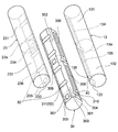
- the perspective view which shows schematic structure of the refrigerant evaporator concerning 1st Embodiment.
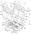
- the perspective view which shows the disassembled perspective structure of the refrigerant evaporator of 1st Embodiment.
- the perspective view which shows the disassembled perspective structure of the windward distribution tank of the refrigerant
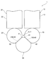
- the perspective view which shows typically the flow of the refrigerant
- the side view which shows the structure of the drainage channel of the refrigerant evaporator of 1st Embodiment.
- the side view which shows the structure of the drainage channel of the 1st modification of the refrigerant evaporator of 1st Embodiment The side view which shows the structure of the drainage channel of the 2nd modification of the refrigerant evaporator of 1st Embodiment.
- the side view which shows the structure of the drainage channel of the 5th modification of the refrigerant evaporator of 1st Embodiment Sectional drawing which shows the cross-section of the windward distribution tank of the refrigerant evaporator concerning 2nd Embodiment, a leeward collection tank, and a replacement tank.
- the refrigerant evaporator 1 of the present embodiment shown in FIG. 1 is used in a refrigeration cycle of a vehicle air conditioner that adjusts the temperature in the passenger compartment.
- the refrigerant evaporator 1 is a cooling heat exchanger that cools air by absorbing heat from air blown into the passenger compartment and evaporating liquid-phase refrigerant.
- the refrigeration cycle includes, in addition to the refrigerant evaporator 1, a compressor, a radiator, an expansion valve, and the like (not shown).
- the refrigerant evaporator 1 includes two evaporation units 10 and 20 and a replacement tank 30.
- the evaporation units 10 and 20 are arranged on the upstream side and the downstream side with respect to the air flow direction X.
- the air flow direction X is a direction orthogonal to the vertical directions Y1 and Y2.
- the evaporator 10 disposed on the upstream side in the air flow direction X is referred to as “windward evaporator 10”.
- the evaporation unit 20 disposed on the downstream side in the air flow direction X is referred to as a “leeward side evaporation unit 20”.
- the windward evaporator 10 includes a windward collecting tank 11, a windward heat exchange unit 12, and a windward distribution tank 13.
- the windward collecting tank 11, the windward heat exchange unit 12, and the windward distribution tank 13 are arranged in this order in the vertical direction downward Y1.
- the windward side heat exchanging part 12 has a cuboid shape.
- the windward heat exchange unit 12 is arranged so that the air flow direction X is the thickness direction.
- a windward distribution tank 13 is attached to an end surface 12d on the Y1 side in the vertical lower direction of the windward heat exchange unit 12.
- a windward collecting tank 11 is attached to an end face 12 e on the Y2 side in the vertical direction of the windward heat exchange unit 12.
- the windward heat exchange unit 12 has a structure in which a plurality of tubes 12a and a plurality of fins 12b are alternately stacked in the horizontal direction. In addition, illustration of the tube 12a and the fin 12b is abbreviate
- the tube 12a has a flat cross section and is arranged to extend in the vertical directions Y1 and Y2.
- a flow path through which a refrigerant flows is formed inside the tube 12a.
- the fins 12b are so-called corrugated fins formed by bending a thin metal plate.
- the fin 12b is arrange
- the windward heat exchange unit 12 is partitioned into a first windward core portion 121 and a second windward core portion 122 in the stacking direction of the tubes 12 a and the fins 12 b.
- the windward heat exchange unit 12 includes side plates 12c at both ends in the stacking direction of the tubes 12a and the fins 12b.
- the side plate 12 c is a member for reinforcing the windward heat exchange unit 12.
- the windward distribution tank 13 is formed of a cylindrical member having a refrigerant flow path therein. Both ends in the axial direction of the upwind distribution tank 13 are closed. As shown in FIG. 2, the upwind distribution tank 13 has a partition plate 13 a at the center in the axial direction. The partition plate 13 a partitions the internal flow path of the windward distribution tank 13 into a first distribution unit 131 and a second distribution unit 132. A plurality of through holes (not shown) are formed on the outer peripheral surface of the windward distribution tank 13 into which the end of the tube 12a on the lower side Y1 in the vertical direction is inserted.
- the internal flow path of the first distribution part 131 communicates with the tube 12a of the first upwind core part 121
- the internal flow path of the second distribution part 132 communicates with the tube 12a of the second upwind core part 122.
- the first distribution unit 131 distributes the refrigerant to the tube 12 a of the first upwind core unit 121.
- the second distribution unit 132 distributes the refrigerant to the tube 12 a of the second upwind core unit 122.
- a flat joint 133 is formed on the outer peripheral surface of the upwind distribution tank 13 so as to extend in the axial direction.
- the joining part 133 is a part to which the replacement tank 30 is joined.
- a through hole 134 that penetrates the internal flow path of the first distribution unit 131 is formed in the joint portion 133.
- the through hole 134 serves as a flow path for guiding the refrigerant in the replacement tank 30 to the first distributor 131.
- a through hole 135 that penetrates the internal flow path of the second distributor 132 is formed in the joint 133.
- the through hole 135 serves as a flow path for guiding the refrigerant in the replacement tank 30 to the second distributor 132.
- the windward collecting tank 11 is formed of a cylindrical member having a refrigerant flow path therein. One end in the axial direction of the windward collecting tank 11 is closed. A refrigerant discharge port 11 a is formed at the other axial end of the windward collecting tank 11. The refrigerant discharge port 11a is connected to the suction side of a compressor (not shown). Further, on the outer peripheral surface of the windward collecting tank 11, a plurality of through holes (not shown) into which the ends on the Y2 side in the vertical direction of the tube 12a are inserted are formed.
- the internal flow path of the windward collecting tank 11 is communicated with the tube 12a of the first windward core part 121 and the tube 12a of the second windward core part 122 through the through holes. That is, the refrigerant flowing through the tube 12 a of the first upwind core portion 121 and the refrigerant flowing through the tube 12 a of the second upwind core portion 122 are collected in the upwind collecting tank 11. The refrigerant collected in the windward collecting tank 11 is guided to the compressor through the refrigerant discharge port 11a.
- the leeward evaporation unit 20 includes a leeward distribution tank 21, a leeward heat exchange unit 22, and a leeward collecting tank 23.
- the leeward side distribution tank 21, the leeward side heat exchange unit 22, and the leeward side collecting tank 23 are arranged in this order in the vertical direction downward Y1.
- the leeward side heat exchanging unit 22 has substantially the same structure as the leeward side heat exchanging unit 12. That is, the leeward side heat exchanging portion 22 has a rectangular parallelepiped shape, and is arranged such that the air flow direction X is the thickness direction.
- the leeward side heat exchanging section 22 has a structure in which a plurality of tubes 22a and a plurality of fins 22b are alternately stacked in the horizontal direction, and has side plates 22c at both ends in the stacking direction of the tubes 22a and the fins 22b. is doing.
- a leeward side collective tank 23 is attached to the end surface 22d of the leeward side heat exchanging unit 22 on the lower side Y1 in the vertical direction.
- a leeward distribution tank 21 is attached to an end face 22e on the Y2 side in the vertical direction of the leeward heat exchange unit 22. Further, as shown in FIG. 2, the leeward side heat exchanging unit 22 includes a first leeward side core portion 221 that faces the first leeward side core portion 121 in the air flow direction X and a second leeward side core portion 122. The second leeward core 222 is opposed to the second leeward core 222.
- the leeward side distribution tank 21 is formed of a cylindrical member having a refrigerant flow path therein. One end of the leeward side distribution tank 21 in the axial direction is closed. A refrigerant inlet 21 a is formed at the other axial end of the leeward distribution tank 21. Low-pressure refrigerant decompressed by an expansion valve (not shown) flows into the refrigerant inlet 21a. Further, on the outer peripheral surface of the leeward side distribution tank 21, a plurality of through holes (not shown) into which the end portion on the Y2 side in the vertical direction of the tube 22a is inserted are formed.
- the internal flow path of the leeward side distribution tank 21 is communicated with the tube 22a of the first leeward side core portion 221 and the tube 22a of the second leeward side core portion 222 through this through hole. That is, the refrigerant flowing into the leeward distribution tank 21 from the refrigerant inlet 21 a is distributed to the tube 22 a of the first leeward core portion 221 and the tube 22 a of the second leeward core portion 222.
- the leeward side collecting tank 23 is formed of a cylindrical member having a refrigerant flow path therein. Both axial ends of the leeward collecting tank 23 are closed.
- the leeward side collective tank 23 has a partition plate 23a at the center in the axial direction. As shown in FIG. 2, the partition plate 23 a partitions the internal flow path of the leeward collecting tank 23 into a first collecting portion 231 and a second collecting portion 232. Further, on the outer peripheral surface of the leeward side collective tank 23, a plurality of through holes (not shown) into which the ends of the tubes 22a on the lower side Y1 in the vertical direction are inserted are formed.
- the internal flow path of the first collecting portion 231 communicates with the tube 22a of the first leeward core portion 221 and the internal flow passage of the second collective portion 232 communicates with the tube 22a of the second leeward core portion 222.
- the refrigerant flowing through the tube 22 a of the first leeward core portion 221 is collected in the first collecting portion 231.
- the refrigerant flowing through the tube 22 a of the second leeward core portion 222 is collected in the second collecting portion 232.
- a planar joint 233 is formed on the outer peripheral surface of the leeward collecting tank 23 so as to extend in the axial direction.
- the joint part 233 is a part to which the replacement tank 30 is joined.
- a through hole 234 that penetrates the internal flow path of the first collecting portion 231 is formed in the joint portion 233.
- the through hole 234 serves as a flow path for guiding the refrigerant in the first collecting portion 231 to the replacement tank 30.
- a through hole 235 that penetrates the internal flow path of the second collecting portion 232 is formed in the joint portion 233.
- the through hole 235 serves as a flow path for guiding the refrigerant in the second collecting portion 232 to the replacement tank 30.
- the leeward side collective tank 23 corresponds to the first tank
- the leeward side heat exchange unit 12 corresponds to the second tank.
- the leeward heat exchange unit 22 corresponds to a first heat exchange unit
- the leeward heat exchange unit 12 corresponds to a second heat exchange unit.
- the replacement tank 30 is provided between the leeward distribution tank 13 and the leeward collective tank 23.
- the replacement tank 30 corresponds to a third tank.
- the replacement tank 30 is formed of a cylindrical member having a refrigerant flow path therein.
- a partition member 301 is provided inside the replacement tank 30. The partition member 301 partitions the internal space of the replacement tank 30 into a first refrigerant channel 302 and a second refrigerant channel 303.
- a planar joint 304 to which the joint 133 of the upwind distribution tank 13 is joined and a joint 233 of the leeward collective tank 23 are joined to the outer peripheral surface of the replacement tank 30. And a planar joining portion 305 are formed.
- a through-hole 306 that penetrates the first coolant channel 302 is formed in the joint 304.
- the through hole 306 is arranged so as to be connected to the through hole 134 of the upwind distribution tank 13.
- a through hole 307 that penetrates through the first coolant channel 302 is formed in the joint portion 305.
- the through hole 307 is arranged so as to be connected to the through hole 235 of the leeward collecting tank 23. That is, the refrigerant collected in the second collecting portion 232 of the leeward collecting tank 23 flows into the first refrigerant flow path 302 through the through hole 235 of the leeward collecting tank 23 and the through hole 307 of the replacement tank 30.
- the refrigerant flowing into the first refrigerant flow path 302 is guided to the first distribution part 131 of the upwind distribution tank 13 through the through hole 306 of the replacement tank 30 and the through hole 134 of the upwind distribution tank 13.
- a through hole 308 that penetrates the second coolant channel 303 is formed in the joint 304.
- the through hole 308 is arranged so as to be connected to the through hole 135 of the upwind distribution tank 13.
- a through hole 309 that penetrates the second refrigerant flow path 303 is formed in the joint portion 305.
- the through hole 309 is arranged so as to be connected to the through hole 234 of the leeward collecting tank 23. That is, the refrigerant collected in the first collecting portion 231 of the leeward side collecting tank 23 flows into the second refrigerant flow path 303 through the through hole 234 of the leeward side collecting tank 23 and the through hole 309 of the replacement tank 30.
- the refrigerant flowing into the second refrigerant flow path 303 is guided to the second distribution part 132 of the upwind distribution tank 13 through the through hole 308 of the replacement tank 30 and the through hole 135 of the upwind distribution tank 13.
- the replacement tank 30 functions as a portion that guides the refrigerant collected in the leeward collecting tank 23 to the leeward distribution tank 13.
- the replacement tank 30 functions as a portion that exchanges the refrigerant flow in the leeward heat exchange unit 22 and the refrigerant flow in the leeward heat exchange unit 12 in the stacking direction of the tubes 12a and 22a.
- the refrigerant depressurized by an expansion valve (not shown) is introduced into the leeward distribution tank 21 from the refrigerant inflow port 21a as indicated by an arrow A in FIG.
- This refrigerant is distributed inside the leeward distribution tank 21 and flows into the first leeward core portion 221 and the second leeward core portion 222 of the leeward distribution tank 21 as indicated by arrows B and C.
- the refrigerant flowing through the tube 22 a of the first leeward core portion 221 is collected in the first collecting portion 231 of the leeward collecting tank 23 as indicated by an arrow D.
- the refrigerant collected in the first collecting portion 231 flows into the second distribution portion 132 of the upwind distribution tank 13 through the second refrigerant flow path 303 of the replacement tank 30 as indicated by an arrow F.
- the refrigerant flowing into the second distribution unit 132 flows into the second upwind core unit 122 as indicated by the arrow H.
- the refrigerant flowing through the tube 22a of the second leeward core portion 222 is collected in the second collecting portion 232 of the leeward collecting tank 23 as indicated by an arrow E.
- the refrigerant collected in the second collecting portion 232 flows into the first distribution portion 131 of the upwind distribution tank 13 through the first refrigerant flow path 302 of the replacement tank 30 as indicated by an arrow G.
- the refrigerant flowing into the first distribution unit 131 flows into the first upwind core unit 121 as indicated by the arrow I.
- the refrigerant flowing through the first windward core portion 121 and the second windward core portion 122 is collected in the windward collecting tank 11 as indicated by arrows K and J. As indicated by an arrow L, the refrigerant collected in the windward collecting tank 11 is supplied from the refrigerant discharge port 11a of the windward collecting tank 11 to the suction side of a compressor (not shown).
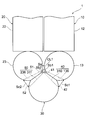
- the condensed water flows downward Y1 in the vertical direction.
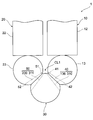
- the condensed water may be stored in a gap CL ⁇ b> 1 between the leeward distribution tank 13, the leeward collecting tank 23, and the replacement tank 30. If the condensed water stored in the gap CL1 freezes as the temperature decreases, there is a risk that so-called freeze cracking will occur, in which the tanks 13, 23, 30 are damaged by the volume expansion of the water.
- the refrigerant evaporator 1 of the present embodiment is provided with a drainage structure for discharging condensed water stored in the gap CL1. Next, details of the drainage structure will be described.
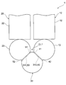
- a plurality of drain grooves 310 are formed in the joint portion 304 of the replacement tank 30 along the slope of the joint portion 304. Further, a drainage groove 136 is formed at a position corresponding to the drainage groove 310 of the joining part 304 of the replacement tank 30 at the joining part 133 of the upwind distribution tank 13. As shown in FIG. 5, linear drainage is performed by a space surrounded by a drainage groove 310 formed in the joint 304 of the replacement tank 30 and a drainage groove 136 formed in the joint 133 of the upwind distribution tank 13. A path 40 is configured. An inlet 41 that opens to the gap CL1 is formed at one end of the drainage channel 40.
- a discharge port 42 that opens into a space on the Y1 side in the vertical direction of the upwind distribution tank 13 is formed.
- the discharge port 42 is disposed on the Y1 side below the gap CL1 in the vertical direction.
- a plurality of drain grooves 311 are formed in the joint portion 305 of the replacement tank 30 along the slope of the joint portion 305. Further, a drainage groove 236 is formed at a position corresponding to the drainage groove 311 of the junction 305 of the replacement tank 30 at the junction 233 of the leeward side collecting tank 23. As shown in FIG. 5, linear drainage is performed by a space surrounded by a drainage groove 311 formed at the junction 305 of the replacement tank 30 and a drainage groove 236 formed at the junction 233 of the leeward side collecting tank 23.
- a path 50 is configured. At one end portion of the drainage channel 50, an inflow port 51 that opens to the gap CL1 is formed.
- a discharge port 52 that opens into a space on the Y1 side in the vertical direction of the leeward side collecting tank 23 is formed.
- the discharge port 52 is disposed on the lower side Y1 in the vertical direction than the gap CL1.
- the drainage grooves 310 and 311 of the replacement tank 30, the drainage groove 136 of the upwind distribution tank 13, and the drainage groove 236 of the leeward side collecting tank 23 are not shown.
- the condensed water stored in the gap CL1 is discharged to the outside through the drainage channel 40 or the drainage channel 50. Therefore, it is difficult for the condensed water to be stored in the gap CL1, and thus it is possible to suppress the freezing crack caused by the freezing of the condensed water.
- the discharge port 42 of the drainage channel 40 and the discharge port 52 of the drainage channel 50 are arranged on the lower Y1 side in the vertical direction than the gap CL1.
- the cross-sectional area of the discharge port 42 of the drainage channel 40 is larger than the cross-sectional area of the inlet 41 of the drainage channel 40.
- the sectional area of the outlet 52 of the drainage channel 50 is larger than the sectional area of the inlet 51 of the drainage channel 50.
- the drainage channels 40 and 50 may be configured only by drainage grooves 310 and 311 formed in the replacement tank 30. Further, as shown in FIG. 8, the drainage channel 40 may be configured only by a drainage groove 136 formed in the windward distribution tank 13. Furthermore, the drainage channel 50 may be configured only by the drainage groove 236 formed in the leeward side collecting tank 23. In short, at least one of the joints 133 and 304 between the windward distribution tank 13 and the replacement tank 30 and the joints 233 and 305 between the leeward collecting tank 23 and the replacement tank 30 shown in FIG. The drainage channel for discharging the stored water should just be formed.
- the drainage channels 40 and 50 may have an arc shape.
- the shapes of the drainage channels 40 and 50 are not limited to the shapes shown in FIGS. 5 to 9 and can be changed as appropriate.
- the cross-sectional area of the gap where the windward distribution tank 13 and the windward collective tank 23 are closest to each other is set to “Sa”. Further, the sectional area of the inlet 41 of the drainage channel 40 is set to “Sb1”, and the sectional area of the discharge port 42 of the drainage channel 40 is set to “Sc1”. Further, the cross-sectional area of the inflow port 51 of the drainage channel 50 is set to “Sb2”, and the cross-sectional area of the discharge port 52 of the drainage channel 50 is set to “Sc2”.
- cross-sectional areas Sa, Sb1, Sb2, Sc1, and Sc2 are set so as to satisfy the following relational expressions f1 and f2.
- the oblique posture indicates a posture in which the longitudinal direction of the tubes 12a and 22a intersects the vertical direction.
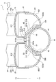
- the leeward distribution tank 13 and the leeward collective tank 23 of the present embodiment are integrally formed.
- the leeward distribution tank 13 and the leeward collective tank 23 are configured to include a core plate 61 and a tank main body 62.
- the tube 12a of the windward heat exchange unit 12 and the tube 22a of the leeward heat exchange unit 22 are inserted and joined to the core plate 61.
- the core plate 61 has a substantially W-shaped cross section. Specifically, the core plate 61 has an upwind tube bonding surface 611 and a leeward tube bonding surface 612.
- the tube 12a of the windward heat exchange unit 12 is inserted and joined to the windward tube joining surface 611.
- the tube 22a of the leeward side heat exchange unit 22 is inserted and joined to the leeward side tube joining surface 612.
- the core plate 61 has a core plate side convex portion 613 disposed between the two tube joint surfaces 611 and 612.
- the core plate side convex part 613 protrudes on the opposite side to the heat exchange parts 12 and 22 from the two tube joint surfaces 611 and 612.
- the core plate-side convex portion 613 is formed with a plurality of openings 613a in the longitudinal direction, that is, in a direction orthogonal to both the air flow direction X and the vertical directions Y1 and Y2.
- the tank main body 62 constitutes a space in the tank together with the core plate 61.
- the space in the tank indicates the first distribution unit 131 and the second distribution unit 132 of the upwind distribution tank 31 and the first collection unit 231 and the second collection unit 232 of the leeward collection tank 23 shown in FIG. .
- the tank body 62 has a substantially W-shaped cross section.
- the tank body 62 includes a windward tank body 621 and a leeward tank body 622.
- the windward side tank main body part 621 constitutes the first distribution part 131 and the second distribution part 132 together with the windward side tube joint surface 611.
- the leeward tank body 622 constitutes a first collecting part 231 and a second collecting part 232 together with the leeward tube joining surface 612.
- the tank main body 62 has a tank main body portion-side convex portion 623 disposed between the two tank main body portions 621 and 622.
- the tank main body side convex portion 623 protrudes further toward the windward side heat exchange unit 12 and the leeward side heat exchange unit 22 than the two tank main body portions 621 and 622.
- a plurality of openings 623a are formed in the tank main body side convex portion 623 in the longitudinal direction, that is, in a direction orthogonal to both the air flow direction X and the vertical directions Y1 and Y2.
- the core plate side convex portion 613 of the core plate 61 and the tank main body side convex portion 623 of the tank main body portion 62 are joined.
- a space formed by the core plate 61 and the tank main body 62 is partitioned into the windward distribution tank 13 and the leeward collecting tank 23.
- the core plate-side convex portion 613 and the tank main body-side convex portion 623 function as a connecting portion 70 that connects the windward distribution tank 13 and the leeward collective tank 23.
- the opening 613a and the opening 623a are arranged so that at least a part of each other overlaps. Thereby, the opening 613a and the opening 623a function as a drainage hole through which condensed water generated on the outer surfaces of the windward heat exchange unit 12 and the leeward heat exchange unit 22 is drained based on heat exchange between the refrigerant and the air. .
- a space CL2 is formed between the upper part of the replacement tank 30 and the tank body 62.
- the space CL2 is communicated with the space in which the windward side heat exchanging unit 12 and the leeward side heat exchanging unit 22 are arranged through the opening 613a and the opening 623a.
- the space CL2 is disposed on the lower side Y1 in the vertical direction than the opening 613a and the opening 623a.
- a joint portion 621a and a joint portion 622a are formed on the outer surface of the tank main body portion 62 located outside when assembled to the core plate 61.
- the joining part 621a is a part joined to the joining part 304 of the replacement tank 30.
- the joint portion 622a is a portion joined to the joint portion 305 of the replacement tank 30.
- the drainage groove 621b is formed in the joining part 621a at a position corresponding to the drainage groove 310 of the joining part 304 of the replacement tank 30.
- a linear drainage channel 40 is constituted by a space surrounded by the drainage groove 310 formed in the joint 304 of the replacement tank 30 and the drainage groove 621b.
- the drainage channel 40 is formed in a portion below the openings 613 a and 623 a formed in the connecting portion 70.
- an inflow port 41 that opens to the space CL2 is formed.
- a discharge port 42 that opens into a space on the Y1 side in the vertical direction of the upwind distribution tank 13 is formed.
- the discharge port 42 is disposed on the lower side Y1 in the vertical direction than the space CL2.
- the space where the windward side heat exchanging unit 12 and the leeward side heat exchanging unit 22 are arranged communicates with the drainage channel 40 via the opening 613a, the opening 623a, and the space CL2.
- the drainage groove 622b is formed in the joint part 622a at a position corresponding to the drainage groove 311 of the joint part 305 of the replacement tank 30.
- a linear drainage channel 50 is configured by a space surrounded by the drainage groove 311 formed in the joint portion 305 of the replacement tank 30 and the drainage groove 622b.
- the drainage channel 50 is formed in a portion below the openings 613 a and 623 a formed in the connecting portion 70.
- An inlet 51 that opens to the space CL2 is formed at one end of the drainage channel 50.
- a discharge port 52 that opens into a space on the Y1 side in the vertical direction of the leeward side collecting tank 23 is formed.
- the discharge port 52 is disposed on the lower Y1 side in the vertical direction than the space CL2.
- the space in which the windward side heat exchange unit 12 and the leeward side heat exchange unit 22 are arranged communicates with the drainage channel 50 through the opening 613a, the opening 623a, and the space CL2.
- the cross-sectional area of at least one of the inlet 41 of the drainage channel 40 and the inlet 51 of the drainage channel 50 is larger than each opening area of the opening 613a and the opening 623a. Thereby, the drainage of the condensed water which flows into space CL2 from the opening part 613a and the opening part 623a can be improved.
- the cross-sectional area of the discharge port 42 of the drainage channel 40 is desirably larger than the cross-sectional area of the inlet 41 of the drainage channel 40.
- the cross-sectional area of the discharge port 52 of the drainage channel 50 is desirably larger than the cross-sectional area of the inlet 51 of the drainage channel 50.
- a through hole serving as a flow path for guiding the refrigerant to the second distributor 132 is formed.
- the joint 622a has a through-hole serving as a flow path for guiding the refrigerant in the first collecting portion 231 to the replacement tank 30, and the replacement tank in which the refrigerant in the second collecting portion 232 is replaced.
- a through hole serving as a flow path for leading to 30 is formed.
- the cross-sectional area of at least one of the inlet 41 of the drainage channel 40 and the inlet 51 of the drainage channel 50 is larger than each opening area of the opening 613a and the opening 623a.
- the refrigerant evaporator 1 of each embodiment may have a structure having only one of the drainage channel 40 and the drainage channel 50.
- the fluid to be cooled in the refrigerant evaporator 1 is not limited to air, and an appropriate fluid can be used.
Landscapes
- Engineering & Computer Science (AREA)
- Physics & Mathematics (AREA)
- Mechanical Engineering (AREA)
- Thermal Sciences (AREA)
- General Engineering & Computer Science (AREA)
- Heat-Exchange Devices With Radiators And Conduit Assemblies (AREA)
- Details Of Heat-Exchange And Heat-Transfer (AREA)
Priority Applications (3)
| Application Number | Priority Date | Filing Date | Title |
|---|---|---|---|
| CN201680006394.9A CN107208943B (zh) | 2015-02-27 | 2016-02-25 | 制冷剂蒸发器 |
| DE112016000954.2T DE112016000954T5 (de) | 2015-02-27 | 2016-02-25 | Kältemittel-Verdampfer |
| US15/536,597 US20170328615A1 (en) | 2015-02-27 | 2016-02-25 | Refrigerant evaporator |
Applications Claiming Priority (2)
| Application Number | Priority Date | Filing Date | Title |
|---|---|---|---|
| JP2015-038169 | 2015-02-27 | ||
| JP2015038169 | 2015-02-27 |
Publications (1)
| Publication Number | Publication Date |
|---|---|
| WO2016136266A1 true WO2016136266A1 (ja) | 2016-09-01 |
Family
ID=56788526
Family Applications (1)
| Application Number | Title | Priority Date | Filing Date |
|---|---|---|---|
| PCT/JP2016/001023 Ceased WO2016136266A1 (ja) | 2015-02-27 | 2016-02-25 | 冷媒蒸発器 |
Country Status (5)
| Country | Link |
|---|---|
| US (1) | US20170328615A1 (enExample) |
| JP (1) | JP6558268B2 (enExample) |
| CN (1) | CN107208943B (enExample) |
| DE (1) | DE112016000954T5 (enExample) |
| WO (1) | WO2016136266A1 (enExample) |
Cited By (2)
| Publication number | Priority date | Publication date | Assignee | Title |
|---|---|---|---|---|
| JP2016164486A (ja) * | 2015-02-27 | 2016-09-08 | 株式会社デンソー | 冷媒蒸発器 |
| JP2017032262A (ja) * | 2015-02-27 | 2017-02-09 | 株式会社デンソー | 冷媒蒸発器 |
Families Citing this family (2)
| Publication number | Priority date | Publication date | Assignee | Title |
|---|---|---|---|---|
| US11035620B1 (en) * | 2020-11-19 | 2021-06-15 | Richard W. Trent | Loop heat pipe transfer system with manifold |
| WO2024224637A1 (ja) * | 2023-04-28 | 2024-10-31 | 三菱電機株式会社 | 熱交換器及び冷凍サイクル装置 |
Citations (5)
| Publication number | Priority date | Publication date | Assignee | Title |
|---|---|---|---|---|
| JP2003214794A (ja) * | 2002-01-23 | 2003-07-30 | Denso Corp | 熱交換器 |
| JP2010197019A (ja) * | 2009-02-27 | 2010-09-09 | Showa Denko Kk | エバポレータ |
| JP2013061136A (ja) * | 2011-09-15 | 2013-04-04 | Keihin Thermal Technology Corp | 車両用空調装置のクーリングユニット |
| JP2013096653A (ja) * | 2011-11-01 | 2013-05-20 | Denso Corp | 冷媒蒸発器 |
| JP2014228234A (ja) * | 2013-05-24 | 2014-12-08 | 株式会社デンソー | 冷媒蒸発器 |
Family Cites Families (11)
| Publication number | Priority date | Publication date | Assignee | Title |
|---|---|---|---|---|
| JP3575497B2 (ja) * | 1994-10-06 | 2004-10-13 | 株式会社デンソー | 受液器一体型冷媒凝縮器およびその製造方法 |
| JP2001050686A (ja) * | 1999-08-05 | 2001-02-23 | Denso Corp | 蒸発器 |
| JP3797109B2 (ja) * | 2001-01-19 | 2006-07-12 | 株式会社デンソー | 蒸発器 |
| JP2006029765A (ja) * | 2004-06-15 | 2006-02-02 | Showa Denko Kk | 熱交換器 |
| CN101115963A (zh) * | 2004-12-16 | 2008-01-30 | 昭和电工株式会社 | 蒸发器 |
| JP2006194576A (ja) * | 2004-12-16 | 2006-07-27 | Showa Denko Kk | エバポレータ |
| US20130006794A1 (en) * | 2011-06-30 | 2013-01-03 | Microsoft Corporation | Online marketplace with offer/bid pooling |
| JP5796518B2 (ja) * | 2012-03-06 | 2015-10-21 | 株式会社デンソー | 冷媒蒸発器 |
| JP5983387B2 (ja) * | 2012-12-14 | 2016-08-31 | 株式会社デンソー | 熱交換器 |
| JP6558269B2 (ja) * | 2015-02-27 | 2019-08-14 | 株式会社デンソー | 冷媒蒸発器 |
| JP6558268B2 (ja) * | 2015-02-27 | 2019-08-14 | 株式会社デンソー | 冷媒蒸発器 |
-
2016
- 2016-02-23 JP JP2016032052A patent/JP6558268B2/ja active Active
- 2016-02-25 DE DE112016000954.2T patent/DE112016000954T5/de not_active Ceased
- 2016-02-25 US US15/536,597 patent/US20170328615A1/en not_active Abandoned
- 2016-02-25 WO PCT/JP2016/001023 patent/WO2016136266A1/ja not_active Ceased
- 2016-02-25 CN CN201680006394.9A patent/CN107208943B/zh active Active
Patent Citations (5)
| Publication number | Priority date | Publication date | Assignee | Title |
|---|---|---|---|---|
| JP2003214794A (ja) * | 2002-01-23 | 2003-07-30 | Denso Corp | 熱交換器 |
| JP2010197019A (ja) * | 2009-02-27 | 2010-09-09 | Showa Denko Kk | エバポレータ |
| JP2013061136A (ja) * | 2011-09-15 | 2013-04-04 | Keihin Thermal Technology Corp | 車両用空調装置のクーリングユニット |
| JP2013096653A (ja) * | 2011-11-01 | 2013-05-20 | Denso Corp | 冷媒蒸発器 |
| JP2014228234A (ja) * | 2013-05-24 | 2014-12-08 | 株式会社デンソー | 冷媒蒸発器 |
Cited By (2)
| Publication number | Priority date | Publication date | Assignee | Title |
|---|---|---|---|---|
| JP2016164486A (ja) * | 2015-02-27 | 2016-09-08 | 株式会社デンソー | 冷媒蒸発器 |
| JP2017032262A (ja) * | 2015-02-27 | 2017-02-09 | 株式会社デンソー | 冷媒蒸発器 |
Also Published As
| Publication number | Publication date |
|---|---|
| DE112016000954T5 (de) | 2017-11-09 |
| JP6558268B2 (ja) | 2019-08-14 |
| US20170328615A1 (en) | 2017-11-16 |
| CN107208943B (zh) | 2020-08-14 |
| JP2016164486A (ja) | 2016-09-08 |
| CN107208943A (zh) | 2017-09-26 |
Similar Documents
| Publication | Publication Date | Title |
|---|---|---|
| US20160223231A1 (en) | Heat exchanger and air conditioner | |
| US10337808B2 (en) | Condenser | |
| WO2017018127A1 (ja) | 熱交換器 | |
| JP6558268B2 (ja) | 冷媒蒸発器 | |
| WO2014041771A1 (ja) | 熱交換器 | |
| CN104769383B (zh) | 冷媒蒸发器 | |
| US20160109168A1 (en) | Refrigerant evaporator | |
| US20070084589A1 (en) | Evaporator | |
| JP6558269B2 (ja) | 冷媒蒸発器 | |
| JP6341099B2 (ja) | 冷媒蒸発器 | |
| CN105229394B (zh) | 制冷剂蒸发器 | |
| JP6717256B2 (ja) | 冷媒蒸発器およびその製造方法 | |
| CN107208948B (zh) | 制冷剂蒸发器 | |
| US12092403B2 (en) | Heat exchanger | |
| JP7146139B1 (ja) | 熱交換器及び空気調和装置 | |
| JP6613996B2 (ja) | 冷媒蒸発器 | |
| WO2016067551A1 (ja) | 積層型熱交換器 | |
| JP6477314B2 (ja) | 冷媒蒸発器 | |
| JP6432275B2 (ja) | 冷媒蒸発器 | |
| JP6536455B2 (ja) | 冷媒蒸発器 | |
| JP6597458B2 (ja) | 冷媒蒸発器 |
Legal Events
| Date | Code | Title | Description |
|---|---|---|---|
| 121 | Ep: the epo has been informed by wipo that ep was designated in this application |
Ref document number: 16755016 Country of ref document: EP Kind code of ref document: A1 |
|
| WWE | Wipo information: entry into national phase |
Ref document number: 15536597 Country of ref document: US |
|
| WWE | Wipo information: entry into national phase |
Ref document number: 112016000954 Country of ref document: DE |
|
| 122 | Ep: pct application non-entry in european phase |
Ref document number: 16755016 Country of ref document: EP Kind code of ref document: A1 |