WO2016136232A1 - 一軸アクチュエータ装置 - Google Patents
一軸アクチュエータ装置 Download PDFInfo
- Publication number
- WO2016136232A1 WO2016136232A1 PCT/JP2016/000928 JP2016000928W WO2016136232A1 WO 2016136232 A1 WO2016136232 A1 WO 2016136232A1 JP 2016000928 W JP2016000928 W JP 2016000928W WO 2016136232 A1 WO2016136232 A1 WO 2016136232A1
- Authority
- WO
- WIPO (PCT)
- Prior art keywords
- timing belt
- tension
- motor
- axis actuator
- actuator device
- Prior art date
- Legal status (The legal status is an assumption and is not a legal conclusion. Google has not performed a legal analysis and makes no representation as to the accuracy of the status listed.)
- Ceased
Links
Images




Classifications
-
- F—MECHANICAL ENGINEERING; LIGHTING; HEATING; WEAPONS; BLASTING
- F16—ENGINEERING ELEMENTS AND UNITS; GENERAL MEASURES FOR PRODUCING AND MAINTAINING EFFECTIVE FUNCTIONING OF MACHINES OR INSTALLATIONS; THERMAL INSULATION IN GENERAL
- F16H—GEARING
- F16H7/00—Gearings for conveying rotary motion by endless flexible members
- F16H7/08—Means for varying tension of belts, ropes or chains
-
- F—MECHANICAL ENGINEERING; LIGHTING; HEATING; WEAPONS; BLASTING
- F16—ENGINEERING ELEMENTS AND UNITS; GENERAL MEASURES FOR PRODUCING AND MAINTAINING EFFECTIVE FUNCTIONING OF MACHINES OR INSTALLATIONS; THERMAL INSULATION IN GENERAL
- F16H—GEARING
- F16H19/00—Gearings comprising essentially only toothed gears or friction members and not capable of conveying indefinitely-continuing rotary motion
- F16H19/02—Gearings comprising essentially only toothed gears or friction members and not capable of conveying indefinitely-continuing rotary motion for interconverting rotary or oscillating motion and reciprocating motion
Definitions
- the present invention relates to a single-axis actuator device that inputs driving force from an output shaft of a motor to an input shaft of a single-axis actuator via a timing belt.
- a single-axis actuator device includes a single-axis actuator having a slide table and a slide table moving structure in which a ball screw mechanism and a linear motion guide mechanism are combined; A motor having an output shaft arranged in parallel with an input shaft of the actuator, and a timing belt mechanism connecting the output shaft of the motor and the input shaft of the single-axis actuator; And a ball screw mechanism for moving the slide table while the linear motion guide mechanism guides the slide table on the axis of the single axis.
- a tension adjusting unit for adjusting the tension of the serial timing belt.
- the tension adjustment unit that adjusts the tension of the timing belt since the tension adjustment unit that adjusts the tension of the timing belt is provided, the tension of the timing belt can be appropriately adjusted. And since this tension adjustment part is provided in the position between the motor and the uniaxial actuator, the tension adjustment part does not affect the external dimensions of the uniaxial actuator device. Therefore, the single-axis actuator device can be made compact while making it possible to adjust the tension of the timing belt.
- the tension adjustment unit includes an adjustment bolt that adjusts the tension of the timing belt, and a lock nut that fixes the position of the adjustment bolt.
- the tension of the timing belt can be adjusted by the adjustment bolt, and the position of the adjustment bolt after adjustment can be fixed by the lock nut. Therefore, it is suitable for preventing or suppressing the loosening of the adjustment bolt due to vibration, aging or the like.
- the tension of the timing belt can be adjusted in a compact configuration.
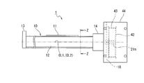
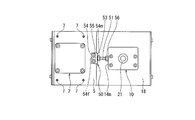
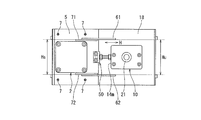
- FIG. 2 is a right side view of FIG. 1 and illustrates a state in which a casing surrounding a timing belt mechanism is removed. It is an enlarged view of the ZZ cross section of FIG. It is a figure explaining the 1st modification of this invention, and the figure respond
- the single-axis actuator device 1 includes a motor 2, a single-axis actuator 10 and a timing belt mechanism 40.
- the motor 2 has its flange 3 attached to the motor bracket 5 with a bolt 9.
- the motor 2 has an output shaft 4 at one end surface, and the output shaft 4 projects to the opposite side of the motor bracket 5.
- the single axis actuator 10 has a slide table 11 and a slide table moving structure for moving the slide table 11.
- the slide table moving structure is configured by combining a ball screw mechanism 20 and a linear motion guide mechanism 30.
- the uniaxial actuator 1 includes an elongated housing 12 having a substantially U-shaped recess 12 u extending in the longitudinal direction at the center of the upper surface. Bearing blocks 13 and 14 are mounted on both ends of the housing 12 respectively.
- the guide rail 31 of the linear motion guide mechanism 30 is fixed to the bottom surface 12 d of the recess 12 u over substantially the entire length in the longitudinal direction.
- the slider 32 of the linear motion guide mechanism 30 is straddled over the guide rail 31 via a rolling element (not shown), as shown in FIG.
- a rolling element circulating mechanism (not shown) for circulating the rolling elements is provided.
- FIG. 5 illustrates a dustproof cover member that covers the gap between the slide table 11 and the opening of the recess 12 u of the housing 12, the cover member is not illustrated in FIG. 1.
- a circular through hole 11b is formed at the center of the slide table 11 at a position above the slider 32 along the axial direction, and a cylindrical ball is formed in the through hole 11b.
- the screw nut 22 is fixed.
- a long screw shaft 21 penetrates the ball screw nut 22 along the axial direction.
- the screw shaft 21 is provided in the recess 12 u of the housing 12, and the bearing blocks 13 and 14 provided at both ends in the longitudinal direction of the housing 12 have their both ends rotatably supported. It is done.
- a thread groove is formed on the outer peripheral surface of the screw shaft 21.
- the ball screw nut 22 shown in FIG. 5 a screw groove (not shown) opposed to the screw groove of the screw shaft 21 is formed.
- the screw shaft 21 and the ball screw nut 22 are screwed together via a plurality of balls (not shown) disposed rotatably between both screw grooves.
- the ball screw nut 22 is provided with a ball circulating mechanism (not shown) for circulating a plurality of balls.
- the screw shaft 21 is an input shaft of the uniaxial actuator 10.
- the end of the screw block 21 on the bearing block 14 side fixed to the uniaxial actuator bracket 18 side is an input portion 21 n, and this input portion 21 n is a bearing block It projects from 14 to the timing belt mechanism 40 side.
- the bearing block 14 supporting the side of the input unit 21 n is attached to the uniaxial actuator bracket 18 with a bolt 21 k as shown in FIG. 4.
- the single-axis actuator bracket 18 is attached to the motor bracket 5 by four bracket fixing bolts 6.
- female screws 7 are equally distributed in four places in the diagonal direction around the position of the axis line CL2 shown in FIG. 1 on the motor bracket 5.
- the uniaxial actuator bracket 18 is disposed in the tensioning direction H of the timing belt 43 (horizontal direction in FIG. 4) at a position facing each female screw 7 of the motor bracket 5 (see FIG. Long holes 8 are respectively extended along the same.
- the two opposing brackets 5 and 18 can be firmly fixed to each other by retightening the four bracket fixing bolts 6 after adjustment by the tension adjustment unit 50 described later.
- the axis line CL2 of the output shaft 4 of the motor 2 is disposed in parallel with the axis line CL1 of the screw shaft 21 which is the input axis of the uniaxial actuator 10.
- the timing belt mechanism 40 connects the output shaft 4 of the motor 2 and the screw shaft 21 which is the input shaft of the uniaxial actuator 10 so as to be able to transmit the driving force.
- the timing belt mechanism 40 includes a drive pulley 41 coaxially fixed to the output shaft 4 of the motor 2, a driven pulley 42 coaxially fixed to the input portion 21 n of the screw shaft 21, and the drive pulley 41. And a timing belt 43 extended over the driven pulley 42.
- the periphery of the timing belt mechanism 40 is entirely covered by a removable casing 44 formed in a rectangular box shape.
- the input portion 21 n of the single-axis actuator 10 and the output shaft 4 of the motor 2 are mutually connected via the timing belt 43 and the output belt of the motor 2 is operated by the timing belt mechanism 40.
- the driving force from 4 is input to the screw shaft 21 of the uniaxial actuator 10.
- the single-axis actuator device 1 is a tension adjustment unit 50 that adjusts the tension of the timing belt 43 of the timing belt mechanism 40 to a position between the motor 2 and the single-axis actuator 10. Is equipped.
- the tension adjustment unit 50 of the present embodiment has an adjustment bolt 51 for adjusting the tension of the timing belt 43 and a lock nut 53 for fixing the position of the adjustment bolt 51.
- the tension adjustment unit 50 has a rectangular parallelepiped attachment block 54 for holding the tension adjustment bolt 51.
- the base end of the mounting block 54 is fixed to the end near the uniaxial actuator of the motor bracket 5 with two upper and lower mounting bolts 55 (see FIG. 3), and horizontally toward the opposite side to the timing belt mechanism 40 It is overhanging.
- a female thread 54 f is formed on the leading end side of the mounting block 54 along the tensioning direction H of the timing belt 43.
- One end of a tension adjustment bolt 51 is screwed into the female screw 54 f.
- the tension adjustment bolt 51 is a threaded rod in which an external thread 51m is formed over the entire length.
- the two nuts 56 and 57 are screwed into the tension adjustment bolt 51.
- One of the two nuts 56, 57 is a tension adjustment nut 56.
- the tension adjustment nut 56 is fixed so as to abut on the side surface 14m of the bearing block 14 of the uniaxial actuator 10 (surface facing the motor 2), and the tension adjustment bolt 51 is tightened by the tension adjustment nut 56 It is designed to adjust the tension of the Another nut 53 is a lock nut.
- the lock nut 53 is fixed so as to abut on the side surface 54 m of the mounting block 54, and can hold the positions of the tension adjustment nut 56 and the adjustment bolt 51 more securely.
- an inlay fitting portion 54k for fitting the motor bracket 5 and the uniaxial actuator bracket 18 is provided at the base of the mounting block 54.
- the inlay fitting portion 54k allows the motor bracket 5 and the uniaxial actuator bracket 18 to move relative to each other in the tensioning direction H of the timing belt 43, while the motor bracket 5 and the uniaxial actuator bracket 18 face each other.
- a fitting structure for restraining mutual movement In the (arrangement direction H and the orthogonal direction), there is provided a fitting structure for restraining mutual movement.
- the tension adjustment unit 50 resists the belt reaction force of the timing belt stretched by the tension by the tightening of the tension adjustment bolt 51 by the fitting structure of the inlay fitting portion 54k, and the output shaft 4 of the motor 2 Is maintained by the tension adjustment unit 50 so that the distance L between the axis CL2 of the motor and the axis CL1 of the screw shaft 21 which is the input shaft of the uniaxial actuator 10 does not change due to the rotation and vibration of the motor 2. It is possible to hold two axes parallel to the screw shaft 21 which is an input axis of the single axis actuator 10.
- the method of tensioning the timing belt 43 by the tension adjustment unit 50 of the single-axis actuator device 1 and the function / effect will be described.
- the operator When adjusting the tension of the timing belt 43 with the single-axis actuator device 1, first, the operator temporarily tightens the four bracket fixing bolts 6 to set the motor bracket in the tensioning direction H of the timing belt 43. The mutual movement of the 5 and 1 axis actuator brackets 18 is made acceptable. Next, the operator tightens the tension adjustment nut 56 so as to abut on the side surface 14 m of the bearing block 14 of the uniaxial actuator 10.
- the motor bracket 5 and the uniaxial actuator bracket 18 slide relative to each other in the stretching direction H in the adjustment range of the elongated hole 8 by the tension of the tension adjustment bolt 51 due to the tightening of the tension adjustment bolt 51. Therefore, the tension of the timing belt 43 can be adjusted.
- the operator determines the position where the tension of the timing belt 43 becomes an appropriate tension by tightening and adjusting the tension adjustment bolt 51, and fixes the tension adjustment nut 56 at that position.
- the single-axis actuator device 1 can stretch the timing belt 43 with an appropriate tension. As described above, since the single-axis actuator device 1 includes the tension adjustment unit 50 that adjusts the tension of the timing belt 43, the tension of the timing belt 43 can be appropriately adjusted.
- the tension adjustment unit 50 since the tension adjustment unit 50 is provided at a position between the motor 2 and the uniaxial actuator 10, the tension adjustment unit 50 affects the external dimensions of the uniaxial actuator device 1. I will not give it. Therefore, according to the single-axis actuator device 1, the single-axis actuator device 1 can be configured to be compact while making it possible to adjust the tension of the timing belt 43.
- the tension adjustment unit 50 has the adjustment bolt 51 for adjusting the tension of the timing belt 43 and the lock nut 53 for fixing the position of the adjustment bolt 51, the tension of the timing belt 43 is caused by the tension of the adjustment bolt 51.
- the tension can be adjusted, and furthermore, the position of the adjustment bolt 51 after adjustment can be more reliably fixed by the lock nut 53. Therefore, the uniaxial actuator device 1 is suitable for preventing or suppressing the loosening of the adjustment bolt 51 due to vibration, aging or the like.
- the single-axis actuator device 1 is provided with an in-row fitting portion 54k at the base of the mounting block 54, and the in-row fitting portion 54k extends in the tensioning direction H of the timing belt 43 with the motor bracket 5 and the single-axis actuator bracket 18 In the facing direction of the motor bracket 5 and the uniaxial actuator bracket 18, there is provided a fitting structure for restraining mutual movement while allowing mutual movement.
- the single-axis actuator device 1 during the tensioning operation of the timing belt 43, the output shaft 4 of the motor 2 is resisted against the belt reaction force of the timing belt 43 tensioned by the tension of the tension adjustment bolt 51. And the screw shaft 21 of the single-axis actuator 10 can be held parallel to each other. As described above, according to this single-axis actuator device 1, the tension of the timing belt 43 can be adjusted with a compact configuration.
- the single-axis actuator device according to the present invention is not limited to the above embodiment, and it goes without saying that various modifications can be made without departing from the spirit of the present invention.
- a various guide structure is employable.
- a pair of motor-side guide plates 71 and 72 which are vertically separated are provided, and a pair of uniaxial-axis-actuator guide plates 61 and 62 which are vertically separated are provided on the uniaxial actuator bracket 18 to configure a guide structure which can slide mutually.
- the guide plates 61, 62, 71, 72 are provided as the guide members constituting the guide structure, but the invention is not limited thereto.
- the motor bracket 5 and the uniaxial actuator bracket 18 are mutually provided.
- a rod or other member may be used as the guide member.
- the guide plates 61, 62, 71, 72 are all mounted in parallel along the stretching direction H, and further, the opposing distance Hs between the pair of motor guide plates 71, 72 and the pair of uniaxial actuator guides
- the plate 61, 62 mutual n opposing distance Hu is set to the same fitting dimension as the inlay fitting portion 54k.
- FIG. 7 shows a modification of the tension adjustment unit.
- a hexagonal bolt 81 is used as the adjustment bolt.
- a cylindrical member 83 is provided between the mounting block 54 and the bearing block 14 as a member corresponding to the tension adjusting nut.
- a female screw 83m is formed along the central axis, and a male screw 81n at the tip of the hexagonal bolt 81 is screwed with the female screw 83m.
- the cylindrical member 83 has a flange 83f at one end, and the flange 83f is disposed opposite to the mounting block 54 side.
- two disc springs 84 and 85 are interposed between the flange 83 f and the mounting block 54.
- the hexagonal bolt 81 is used as an adjustment bolt and the hexagonal bolt 81 is screwed to the cylindrical member 83 and tightened, the two disc springs 84 and 85 interposed are compressed Be done. Therefore, by appropriately tightening the hexagonal bolt 81, the tension of the timing belt 43 can be adjusted by the elastic force of the two disc springs 84 and 85 interposed. In the example shown in the figure, two disc springs 84 and 85 are interposed. However, the present invention is not limited thereto. If tension of the timing belt 43 can be adjusted by the elastic force of the springs, Various springs, such as a spring washer and a cylindrical coil spring, can be used. Also, the number of springs interposed is of course not limited to two, and may be one or three or more.
Landscapes
- Engineering & Computer Science (AREA)
- General Engineering & Computer Science (AREA)
- Mechanical Engineering (AREA)
- Transmission Devices (AREA)
- Devices For Conveying Motion By Means Of Endless Flexible Members (AREA)
Abstract
タイミングベルトの張力をコンパクトな構成で調整する。モータ(2)と一軸アクチュエータ(10)との間の位置に、タイミングベルト(43)の張力を調整する張力調整部(50)を設けた。
Description
本発明は、モータの出力軸からの駆動力を、タイミングベルトを介して一軸アクチュエータの入力軸に入力する一軸アクチュエータ装置に関する。
この種の一軸アクチュエータ装置として、例えば特許文献1ないし2に記載の技術が開示されている。これら文献に記載されるように、この種の一軸アクチュエータ装置は、モータの出力軸と一軸アクチュエータの入力軸との間にタイミングベルトが架け渡され、モータの出力軸からの駆動力が一軸アクチュエータの入力軸に入力されるようになっている。
しかし、特許文献1記載の技術では、タイミングベルトは、「張力がかかった状態に取り付けられる」と記載されるものの、同文献の開示からは、タイミングベルトの張力を調整するための構造が不明である。そのため、タイミングベルトの張力を適切に調整する上で検討の余地がある。
これに対し、特許文献2記載の技術では、タイミングベルトを有するタイミングベルト機構が折り返しボックス内に収容され、モータがL金具を介して折り返しボックスに取付けられている。そして、L金具の外側面には調整ねじが外側面から張り出して取り付けられ、この調整ねじを締め込んで、調整ねじの先端を折り返しボックスの外側面に押し付けることにより、タイミングベルトの張力を調整可能になっている。
これに対し、特許文献2記載の技術では、タイミングベルトを有するタイミングベルト機構が折り返しボックス内に収容され、モータがL金具を介して折り返しボックスに取付けられている。そして、L金具の外側面には調整ねじが外側面から張り出して取り付けられ、この調整ねじを締め込んで、調整ねじの先端を折り返しボックスの外側面に押し付けることにより、タイミングベルトの張力を調整可能になっている。
しかしながら、特許文献2記載の技術では、調整ねじがL金具の外側面から張り出して取り付けられているので、一軸アクチュエータ装置の外形寸法が大きくなるという問題がある。また、張り出している調整ねじが他の部材と干渉するおそれがある。さらに、調整ねじで押し付けた力で調整位置を保持するものの、振動や経時変化等により調整ねじが緩むおそれがある。
そこで、本発明は、このような問題点に着目してなされたものであって、タイミングベルトの張力をコンパクトな構成で調整し得る一軸アクチュエータ装置を提供することを課題とする。
そこで、本発明は、このような問題点に着目してなされたものであって、タイミングベルトの張力をコンパクトな構成で調整し得る一軸アクチュエータ装置を提供することを課題とする。
上記課題を解決するために、本発明の一態様に係る一軸アクチュエータ装置は、スライドテーブルと、ボールねじ機構と直動案内機構とが組み合わされたスライドテーブル移動構造とを有する一軸アクチュエータと、該一軸アクチュエータの入力軸と並行に配置される出力軸を有するモータと、前記モータの出力軸と前記一軸アクチュエータの入力軸とを繋ぐタイミングベルト機構とを備え、前記タイミングベルト機構により前記モータの出力軸からの駆動力が前記一軸アクチュエータの入力軸にタイミングベルトを介して入力されて、前記スライドテーブルを一の軸線上で前記直動案内機構により案内しつつ前記ボールねじ機構により移動させる一軸アクチュエータ装置であって、前記モータと前記一軸アクチュエータとの間の位置に、前記タイミングベルトの張力を調整する張力調整部を有することを特徴とする。
本発明の一態様に係る一軸アクチュエータ装置によれば、タイミングベルトの張力を調整する張力調整部を有するので、タイミングベルトの張力を適切に調整することができる。そして、この張力調整部は、モータと一軸アクチュエータとの間の位置に設けられているので、一軸アクチュエータ装置の外形寸法に張力調整部が影響を与えることがない。よって、タイミングベルトの張力を調整可能としつつ、一軸アクチュエータ装置をコンパクトに構成することができる。
ここで、本発明の一態様に係る一軸アクチュエータ装置において、前記張力調整部は、前記タイミングベルトの張力を調整する調整用ボルトと、該調整用ボルトの位置を固定するロックナットとを有することは好ましい。
このような構成であれば、調整用ボルトによってタイミングベルトの張力を調整可能とし、さらに、ロックナットによって、調整後の調整用ボルトの位置を固定することができる。そのため、振動や経時変化等による調整用ボルトの緩みを防止または抑制する上で好適である。
このような構成であれば、調整用ボルトによってタイミングベルトの張力を調整可能とし、さらに、ロックナットによって、調整後の調整用ボルトの位置を固定することができる。そのため、振動や経時変化等による調整用ボルトの緩みを防止または抑制する上で好適である。
上述のように、本発明によれば、タイミングベルトの張力をコンパクトな構成で調整することができる。
以下、本発明の一実施形態について、図面を適宜参照しつつ説明する。なお、図面は模式的なものである。そのため、厚みと平面寸法との関係、比率等は現実のものとは異なることに留意すべきであり、図面相互間においても互いの寸法の関係や比率が異なる部分が含まれている。また、以下に示す実施形態は、本発明の技術的思想を具体化するための装置や方法を例示するものであって、本発明の技術的思想は、構成部品の材質、形状、構造、配置等を下記の実施形態に特定するものではない。
図1に示すように、この一軸アクチュエータ装置1は、モータ2、一軸アクチュエータ10およびタイミングベルト機構40を備える。モータ2は、自身のフランジ3がモータブラケット5にボルト9で取り付けられている。モータ2は、一端面に出力軸4を有し、出力軸4は、モータブラケット5の反対側まで張り出している。
一軸アクチュエータ10は、スライドテーブル11と、スライドテーブル11を移動させるスライドテーブル移動構造とを有する。スライドテーブル移動構造は、ボールねじ機構20と直動案内機構30とが組み合わされて構成されている。
一軸アクチュエータ10は、スライドテーブル11と、スライドテーブル11を移動させるスライドテーブル移動構造とを有する。スライドテーブル移動構造は、ボールねじ機構20と直動案内機構30とが組み合わされて構成されている。
詳しくは、本実施形態の一軸アクチュエータ1は、長手方向に延びる略U字状の凹部12uを上面中央部に有する長尺な筐体12を備える。筐体12の両端には、軸受ブロック13,14がそれぞれ装着されている。筐体12の凹部12u内には、凹部12uの底面12dに、直動案内機構30の案内レール31が長手方向の略全長に亘って固定されている。
案内レール31上には、図5に筐体12の断面を示すように、直動案内機構30のスライダ32が、転動体(不図示)を介して跨設されている。スライダ32内には、転動体を循環させるための転動体循環機構(不図示)が設けられている。
案内レール31上には、図5に筐体12の断面を示すように、直動案内機構30のスライダ32が、転動体(不図示)を介して跨設されている。スライダ32内には、転動体を循環させるための転動体循環機構(不図示)が設けられている。
スライダ32の上部には、ブロック状のスライドテーブル11が固定されている。スライドテーブル11は、直動案内機構30のスライダ32と一体に案内レール31に沿ってスライド移動可能になっている。なお、図5では、スライドテーブル11と筐体12の凹部12uの開口部との隙間を覆う防塵用のカバー部材を図示しているが、図1ではカバー部材の図示を省略している。
さらに、スライドテーブル11の中央には、図5に示すように、スライダ32よりも上方の位置に、軸方向に沿って円形の貫通孔11bが形成され、この貫通孔11bに、円筒状のボールねじナット22が固定されている。ボールねじナット22には、長尺なねじ軸21が軸方向に沿って貫通している。
さらに、スライドテーブル11の中央には、図5に示すように、スライダ32よりも上方の位置に、軸方向に沿って円形の貫通孔11bが形成され、この貫通孔11bに、円筒状のボールねじナット22が固定されている。ボールねじナット22には、長尺なねじ軸21が軸方向に沿って貫通している。
ねじ軸21は、図1に示すように、筐体12の凹部12u内に設けられ、筐体12の長手方向両端部に設けられた軸受ブロック13,14に、自身両端部が回転自在に支持されている。ねじ軸21の外周面には、ねじ溝が形成されている。一方、図5に示したボールねじナット22の内周面には、ねじ軸21のねじ溝に対向するねじ溝(不図示)が形成されている。ねじ軸21とボールねじナット22とは、両ねじ溝間に転動自在に配設された複数のボール(不図示)を介して螺合している。また、ボールねじナット22には、複数のボールを循環させるためのボール循環機構(不図示)が設けられている。
ここで、ねじ軸21は、一軸アクチュエータ10の入力軸になっている。図1に示すように、本実施形態では、ねじ軸21は、一軸アクチュエータブラケット18側に固定された軸受ブロック14側の端部が入力部21nとなっており、この入力部21nが、軸受ブロック14からタイミングベルト機構40側に張り出している。
入力部21nの側を支持する軸受ブロック14は、図4に示すように、一軸アクチュエータブラケット18にボルト21kで取り付けられている。また、一軸アクチュエータブラケット18は、4本のブラケット固定ボルト6によって、モータブラケット5に取り付けられる。モータブラケット5には、図1に示す軸線CL2の位置を中心として、図3に示すように、対角線方向の4か所に雌ねじ7が等配して設けられている。
入力部21nの側を支持する軸受ブロック14は、図4に示すように、一軸アクチュエータブラケット18にボルト21kで取り付けられている。また、一軸アクチュエータブラケット18は、4本のブラケット固定ボルト6によって、モータブラケット5に取り付けられる。モータブラケット5には、図1に示す軸線CL2の位置を中心として、図3に示すように、対角線方向の4か所に雌ねじ7が等配して設けられている。
また、一軸アクチュエータブラケット18には、モータブラケット5の各雌ねじ7(図1参照)に対向する位置に、図4に示すように、タイミングベルト43の張設方向H(同図の水平方向)に沿って長穴8がそれぞれ延設されている。これにより、対面する二つのブラケット5、18の相互は、後述する張力調整部50での調整後に、4本のブラケット固定ボルト6を増し締めすることによって強固に固定可能になっている。
上記構成により、図1に示すように、モータ2の出力軸4の軸線CL2は、一軸アクチュエータ10の入力軸であるねじ軸21の軸線CL1と並行に配置される。そして、上記タイミングベルト機構40は、モータ2の出力軸4と一軸アクチュエータ10の入力軸であるねじ軸21とを駆動力を伝達可能に繋いでいる。
上記構成により、図1に示すように、モータ2の出力軸4の軸線CL2は、一軸アクチュエータ10の入力軸であるねじ軸21の軸線CL1と並行に配置される。そして、上記タイミングベルト機構40は、モータ2の出力軸4と一軸アクチュエータ10の入力軸であるねじ軸21とを駆動力を伝達可能に繋いでいる。
本実施形態では、タイミングベルト機構40は、モータ2の出力軸4に同軸に固定される駆動プーリ41と、ねじ軸21の入力部21nに同軸に固定される従動プーリ42と、駆動プーリ41と従動プーリ42とに架け渡されるタイミングベルト43とを有する。なお、タイミングベルト機構40の周囲は、直方体状の箱型に形成された着脱可能なケーシング44によって全体が覆われている。
この一軸アクチュエータ装置1は、上述の構成により、一軸アクチュエータ10の入力部21nとモータ2の出力軸4とは、相互にタイミングベルト43を介して連結され、タイミングベルト機構40によりモータ2の出力軸4からの駆動力が一軸アクチュエータ10のねじ軸21に入力される。
この一軸アクチュエータ装置1は、上述の構成により、一軸アクチュエータ10の入力部21nとモータ2の出力軸4とは、相互にタイミングベルト43を介して連結され、タイミングベルト機構40によりモータ2の出力軸4からの駆動力が一軸アクチュエータ10のねじ軸21に入力される。
これにより、回転駆動力が入力軸であるねじ軸21に入力されると、回転駆動力は、ボールねじ機構20によりボールねじナット22の直線方向への推進力に変換され、ボールねじナット22と一体に設けられたスライドテーブル11が、一の軸線CL1上で直動案内機構30により案内されつつボールねじ機構20により移動するようになっている。
ここで、この一軸アクチュエータ装置1は、図1および図3に示すように、モータ2と一軸アクチュエータ10との間の位置に、タイミングベルト機構40のタイミングベルト43の張力を調整する張力調整部50を備えている。本実施形態の張力調整部50は、タイミングベルト43の張力を調整する調整用ボルト51と、調整用ボルト51の位置を固定するロックナット53とを有する。
ここで、この一軸アクチュエータ装置1は、図1および図3に示すように、モータ2と一軸アクチュエータ10との間の位置に、タイミングベルト機構40のタイミングベルト43の張力を調整する張力調整部50を備えている。本実施形態の張力調整部50は、タイミングベルト43の張力を調整する調整用ボルト51と、調整用ボルト51の位置を固定するロックナット53とを有する。
詳しくは、この張力調整部50は、張力調整ボルト51を保持するための直方体状の取付けブロック54を有する。取付けブロック54の基端部は、モータブラケット5の一軸アクチュエータ寄りの端部に、上下二本の取付けボルト55(図3参照)で固定され、タイミングベルト機構40とは反対側に向けて水平に張り出している。
取付けブロック54の先端側には、雌ねじ54fがタイミングベルト43の張設方向Hに沿って形成されている。雌ねじ54fには、張力調整ボルト51の一端がねじ込まれる。張力調整ボルト51は、全長に亘って雄ねじ51mが形成されているねじ棒である。張力調整ボルト51には、二つのナット56、57が螺合されている。二つのナット56、57の一方が張力調整ナット56である。
取付けブロック54の先端側には、雌ねじ54fがタイミングベルト43の張設方向Hに沿って形成されている。雌ねじ54fには、張力調整ボルト51の一端がねじ込まれる。張力調整ボルト51は、全長に亘って雄ねじ51mが形成されているねじ棒である。張力調整ボルト51には、二つのナット56、57が螺合されている。二つのナット56、57の一方が張力調整ナット56である。
張力調整ナット56は、一軸アクチュエータ10の軸受ブロック14の側面(モータ2に対向する面)14mに当接するように固定され、張力調整ナット56の締め込みによる張力調整ボルト51の突っ張りによってタイミングベルト43の張力を調整するようになっている。他のナット53はロックナットである。ロックナット53は、取付けブロック54の側面54mに当接するように固定され、張力調整ナット56および調整用ボルト51の位置をより確実に保持可能になっている。
取付けブロック54の基部には、モータブラケット5と一軸アクチュエータブラケット18とを嵌合させるインロー嵌合部54kが設けられている。このインロー嵌合部54kは、タイミングベルト43の張設方向Hには、モータブラケット5と一軸アクチュエータブラケット18との相互の移動を許容しつつ、モータブラケット5と一軸アクチュエータブラケット18との対面する方向(張設方向Hと直交方向)には、相互の移動を拘束する嵌合構造を有する。
取付けブロック54の基部には、モータブラケット5と一軸アクチュエータブラケット18とを嵌合させるインロー嵌合部54kが設けられている。このインロー嵌合部54kは、タイミングベルト43の張設方向Hには、モータブラケット5と一軸アクチュエータブラケット18との相互の移動を許容しつつ、モータブラケット5と一軸アクチュエータブラケット18との対面する方向(張設方向Hと直交方向)には、相互の移動を拘束する嵌合構造を有する。
これにより、この張力調整部50は、インロー嵌合部54kの嵌合構造によって、張力調整ボルト51の締め付けによる突っ張りによって張設されたタイミングベルトのベルト反力に抗し、モータ2の出力軸4の軸線CL2と一軸アクチュエータ10の入力軸であるねじ軸21の軸線CL1との距離Lが、モータ2の回転、振動により変化しないように張力調整部50によって維持し、モータ2の出力軸4と一軸アクチュエータ10の入力軸であるねじ軸21との二軸の並行を保持可能になっている。
次に、この一軸アクチュエータ装置1の張力調整部50によるタイミングベルト43の張設方法および作用・効果について説明する。
この一軸アクチュエータ装置1でタイミングベルト43の張力を調整する際は、まず、作業者は、4本のブラケット固定ボルト6を仮締め状態にして、タイミングベルト43の張設方向Hに対し、モータブラケット5と一軸アクチュエータブラケット18相互の移動を許容可能な状態とする。
次いで、作業者は、一軸アクチュエータ10の軸受ブロック14の側面14mに、張力調整ナット56を当接するように締め込む。これにより、張力調整ボルト51の締め付けによる張力調整ボルト51の突っ張りによって、モータブラケット5と一軸アクチュエータブラケット18とは、長穴8の調整範囲で張設方向Hに相対的にスライド移動する。そのため、タイミングベルト43の張力を調整することができる。作業者は、張力調整ボルト51の締め付け加減により、タイミングベルト43の張力が適切な張力となる位置を決定し、その位置にて張力調整ナット56を固定する。
この一軸アクチュエータ装置1でタイミングベルト43の張力を調整する際は、まず、作業者は、4本のブラケット固定ボルト6を仮締め状態にして、タイミングベルト43の張設方向Hに対し、モータブラケット5と一軸アクチュエータブラケット18相互の移動を許容可能な状態とする。
次いで、作業者は、一軸アクチュエータ10の軸受ブロック14の側面14mに、張力調整ナット56を当接するように締め込む。これにより、張力調整ボルト51の締め付けによる張力調整ボルト51の突っ張りによって、モータブラケット5と一軸アクチュエータブラケット18とは、長穴8の調整範囲で張設方向Hに相対的にスライド移動する。そのため、タイミングベルト43の張力を調整することができる。作業者は、張力調整ボルト51の締め付け加減により、タイミングベルト43の張力が適切な張力となる位置を決定し、その位置にて張力調整ナット56を固定する。
次いで、作業者は、取付けブロック54の側面54mにロックナット53が当接するようにロックナット53を締め込んで、張力調整ナット56および調整用ボルト51の位置をより確実に保持する。次いで、作業者は、タイミングベルト43の張力が適切な張力であることを確認しつつ、4本のブラケット固定ボルト6を所定トルクで本締めする。これにより、この一軸アクチュエータ装置1は、タイミングベルト43を適切な張力で張り渡すことができる。
このように、この一軸アクチュエータ装置1は、タイミングベルト43の張力を調整する張力調整部50を有するので、タイミングベルト43の張力を適切に調整することができる。そして、この一軸アクチュエータ装置1によれば、張力調整部50は、モータ2と一軸アクチュエータ10との間の位置に設けられているので、一軸アクチュエータ装置1の外形寸法に張力調整部50が影響を与えることがない。よって、この一軸アクチュエータ装置1によれば、タイミングベルト43の張力を調整可能としつつ、一軸アクチュエータ装置1をコンパクトに構成することができる。
このように、この一軸アクチュエータ装置1は、タイミングベルト43の張力を調整する張力調整部50を有するので、タイミングベルト43の張力を適切に調整することができる。そして、この一軸アクチュエータ装置1によれば、張力調整部50は、モータ2と一軸アクチュエータ10との間の位置に設けられているので、一軸アクチュエータ装置1の外形寸法に張力調整部50が影響を与えることがない。よって、この一軸アクチュエータ装置1によれば、タイミングベルト43の張力を調整可能としつつ、一軸アクチュエータ装置1をコンパクトに構成することができる。
さらに、張力調整部50は、タイミングベルト43の張力を調整する調整用ボルト51と、調整用ボルト51の位置を固定するロックナット53とを有するので、調整用ボルト51の突っ張りによってタイミングベルト43の張力を調整可能とし、さらに、ロックナット53によって、調整後の調整用ボルト51の位置をより確実に固定することができる。そのため、この一軸アクチュエータ装置1によれば、振動や経時変化等による調整用ボルト51の緩みを防止または抑制する上で好適である。
また、この一軸アクチュエータ装置1は、取付けブロック54の基部にインロー嵌合部54kが設けられ、インロー嵌合部54kは、タイミングベルト43の張設方向Hには、モータブラケット5と一軸アクチュエータブラケット18と相互の移動を許容しつつ、モータブラケット5と一軸アクチュエータブラケット18との対面する方向には、相互の移動を拘束する嵌合構造を有する。
また、この一軸アクチュエータ装置1は、取付けブロック54の基部にインロー嵌合部54kが設けられ、インロー嵌合部54kは、タイミングベルト43の張設方向Hには、モータブラケット5と一軸アクチュエータブラケット18と相互の移動を許容しつつ、モータブラケット5と一軸アクチュエータブラケット18との対面する方向には、相互の移動を拘束する嵌合構造を有する。
よって、この一軸アクチュエータ装置1によれば、タイミングベルト43の張設作業中において、張力調整ボルト51の突っ張りによって張設されたタイミングベルト43のベルト反力に抗して、モータ2の出力軸4と一軸アクチュエータ10のねじ軸21との二軸の並行を保持することができる。
以上説明したように、この一軸アクチュエータ装置1によれば、タイミングベルト43の張力をコンパクトな構成で調整することができる。なお、本発明に係る一軸アクチュエータ装置は、上記実施形態に限定されるものではなく、本発明の趣旨を逸脱しなければ種々の変形が可能であることは勿論である。
以上説明したように、この一軸アクチュエータ装置1によれば、タイミングベルト43の張力をコンパクトな構成で調整することができる。なお、本発明に係る一軸アクチュエータ装置は、上記実施形態に限定されるものではなく、本発明の趣旨を逸脱しなければ種々の変形が可能であることは勿論である。
例えば、上記実施形態では、取付けブロック54の基部に、インロー嵌合部54kを設けた例を説明したが、これに限定されず、種々の案内構造を採用することができる。
例えば、上記インロー嵌合部54kに加えて、または、インロー嵌合部54kに替えて、図6に変形例を示すように、タイミングベルト43の張設方向Hに沿って、モータブラケット5に、上下に離隔した一対のモータ側ガイド板71,72を設けるとともに、一軸アクチュエータブラケット18に、上下に離隔した一対の一軸アクチュエータ側ガイド板61,62を設けて相互にスライド移動可能な案内構造を構成してもよい。
例えば、上記インロー嵌合部54kに加えて、または、インロー嵌合部54kに替えて、図6に変形例を示すように、タイミングベルト43の張設方向Hに沿って、モータブラケット5に、上下に離隔した一対のモータ側ガイド板71,72を設けるとともに、一軸アクチュエータブラケット18に、上下に離隔した一対の一軸アクチュエータ側ガイド板61,62を設けて相互にスライド移動可能な案内構造を構成してもよい。
なお、同図の例では、案内構造を構成するガイド部材として、ガイド板61,62、71,72を設けた例を示したが、これに限らず、モータブラケット5と一軸アクチュエータブラケット18相互をスライド移動可能な案内構造を構成可能であれば、ガイド部材として、棒材等その他の部材を用いてもよい。
各ガイド板61,62、71,72は、全て張設方向Hに沿って平行に装着されており、さらに、一対のモータ側ガイド板71,72相互の対向距離Hsと一対の一軸アクチュエータ側ガイド板61,62相互n対向距離Huとは、インロー嵌合部54k同様の嵌合寸法に設定されている。
各ガイド板61,62、71,72は、全て張設方向Hに沿って平行に装着されており、さらに、一対のモータ側ガイド板71,72相互の対向距離Hsと一対の一軸アクチュエータ側ガイド板61,62相互n対向距離Huとは、インロー嵌合部54k同様の嵌合寸法に設定されている。
よって、このような案内構造であっても、タイミングベルト43の張設方向Hには、モータブラケット5と一軸アクチュエータブラケット18との相互の移動を許容しつつ、張設方向Hと直交方向には、相互の移動を拘束することができる。そのため、タイミングベルト43を張設時のプーリ41,42の姿勢を安定させて、タイミングベルト43の張力をコンパクトな構成で容易に調整することができる。
また、張力調整部50の構成についても、上記実施形態に限定されず、タイミングベルト43の張力を調整可能であれば、種々の態様を採用できる。例えば、上記実施形態の第二変形例として、図7に張力調整部の変形例を示す。
また、張力調整部50の構成についても、上記実施形態に限定されず、タイミングベルト43の張力を調整可能であれば、種々の態様を採用できる。例えば、上記実施形態の第二変形例として、図7に張力調整部の変形例を示す。
同図に示すように、この変形例では、調整用ボルトとして、六角ボルト81を用いている。そして、取付けブロック54と軸受ブロック14との間には、上記張力調整ナットに対応する部材として、円筒部材83が設けられている。円筒部材83は、中心軸に沿って雌ねじ83mが形成され、六角ボルト81の先端の雄ねじ81nが雌ねじ83mに螺合している。
この円筒部材83は、一端にフランジ83fを有し、フランジ83fは、取付けブロック54側に対向配置されている。そして、フランジ83fと取付けブロック54との間には、二枚の皿ばね84、85が介装されている。
この円筒部材83は、一端にフランジ83fを有し、フランジ83fは、取付けブロック54側に対向配置されている。そして、フランジ83fと取付けブロック54との間には、二枚の皿ばね84、85が介装されている。
この第二変形例の構成であれば、六角ボルト81を調整用ボルトとし、六角ボルト81を円筒部材83に螺合させて締め込むにつれ、介装された二枚の皿ばね84、85が圧縮される。そのため、六角ボルト81を適切に締め付けることにより、介装された二枚の皿ばね84、85の弾性力でタイミングベルト43の張力を調整できる。
なお、同図の例では、二枚の皿ばね84、85が介装された例を示しているが、これに限らず、タイミングベルト43の張力をばねの弾性力によって調整可能であれば、ばね座金や円筒コイルばね等、種々のばねを用いることができる。また、ばねの介装数も二枚に限定されないことは勿論であり、一枚または三枚以上としてもよい。
なお、同図の例では、二枚の皿ばね84、85が介装された例を示しているが、これに限らず、タイミングベルト43の張力をばねの弾性力によって調整可能であれば、ばね座金や円筒コイルばね等、種々のばねを用いることができる。また、ばねの介装数も二枚に限定されないことは勿論であり、一枚または三枚以上としてもよい。
1 一軸アクチュエータ装置
2 モータ
3 フランジ
4 出力軸
5 モータブラケット
6 ブラケット固定ボルト
7 雌ねじ
8 長穴
9 ボルト
10 一軸アクチュエータ
11 スライドテーブル
12 筐体
13 軸受ブロック
14 軸受ブロック
18 一軸アクチュエータブラケット
20 ボールねじ機構
21 ねじ軸(入力軸)
22 ボールねじナット
30 直動案内機構
31 案内レール
32 スライダ
40 タイミングベルト機構
41 駆動プーリ
42 従動プーリ
43 タイミングベルト
44 ケーシング
50 張力調整部
51 調整用ボルト
53 ロックナット
54 取付けブロック
55 取付けボルト
56 張力調整ナット
2 モータ
3 フランジ
4 出力軸
5 モータブラケット
6 ブラケット固定ボルト
7 雌ねじ
8 長穴
9 ボルト
10 一軸アクチュエータ
11 スライドテーブル
12 筐体
13 軸受ブロック
14 軸受ブロック
18 一軸アクチュエータブラケット
20 ボールねじ機構
21 ねじ軸(入力軸)
22 ボールねじナット
30 直動案内機構
31 案内レール
32 スライダ
40 タイミングベルト機構
41 駆動プーリ
42 従動プーリ
43 タイミングベルト
44 ケーシング
50 張力調整部
51 調整用ボルト
53 ロックナット
54 取付けブロック
55 取付けボルト
56 張力調整ナット
Claims (2)
- スライドテーブルと、ボールねじ機構と直動案内機構とが組み合わされたスライドテーブル移動構造とを有する一軸アクチュエータと、該一軸アクチュエータの入力軸と並行に配置される出力軸を有するモータと、前記モータの出力軸と前記一軸アクチュエータの入力軸とを繋ぐタイミングベルト機構とを備え、
前記タイミングベルト機構により前記モータの出力軸からの駆動力が前記一軸アクチュエータの入力軸にタイミングベルトを介して入力されて、前記スライドテーブルを一の軸線上で前記直動案内機構により案内しつつ前記ボールねじ機構により移動させる一軸アクチュエータ装置であって、
前記モータと前記一軸アクチュエータとの間の位置に、前記タイミングベルトの張力を調整する張力調整部を有することを特徴とする一軸アクチュエータ装置。 - 前記張力調整部は、前記タイミングベルトの張力を調整する調整用ボルトと、該調整用ボルトの位置を固定するロックナットとを有する請求項1に記載の一軸アクチュエータ装置。
Applications Claiming Priority (6)
| Application Number | Priority Date | Filing Date | Title |
|---|---|---|---|
| JP2015032904 | 2015-02-23 | ||
| JP2015-032904 | 2015-02-23 | ||
| JP2015132265A JP2018084243A (ja) | 2015-07-01 | 2015-07-01 | 一軸アクチュエータ装置 |
| JP2015-132265 | 2015-07-01 | ||
| JP2016-020389 | 2016-02-05 | ||
| JP2016020389A JP2018084244A (ja) | 2016-02-05 | 2016-02-05 | 一軸アクチュエータ装置 |
Publications (1)
| Publication Number | Publication Date |
|---|---|
| WO2016136232A1 true WO2016136232A1 (ja) | 2016-09-01 |
Family
ID=56788353
Family Applications (1)
| Application Number | Title | Priority Date | Filing Date |
|---|---|---|---|
| PCT/JP2016/000928 Ceased WO2016136232A1 (ja) | 2015-02-23 | 2016-02-22 | 一軸アクチュエータ装置 |
Country Status (1)
| Country | Link |
|---|---|
| WO (1) | WO2016136232A1 (ja) |
Citations (4)
| Publication number | Priority date | Publication date | Assignee | Title |
|---|---|---|---|---|
| JPH0828638A (ja) * | 1994-07-12 | 1996-02-02 | Fanuc Ltd | ベルトあるいはチェーンのテンション調整装置 |
| JP2002048202A (ja) * | 2000-05-24 | 2002-02-15 | Ge Medical Systems Global Technology Co Llc | 巻き掛け伝動機構の巻き掛け部材張力調整方法および装置、巻き掛け部材張力測定方法および装置ならびにct装置 |
| JP2003220959A (ja) * | 2002-01-29 | 2003-08-05 | Koyo Seiko Co Ltd | 電動パワーステアリング装置 |
| JP2014070698A (ja) * | 2012-09-28 | 2014-04-21 | Iai Corp | アクチュエータ |
-
2016
- 2016-02-22 WO PCT/JP2016/000928 patent/WO2016136232A1/ja not_active Ceased
Patent Citations (4)
| Publication number | Priority date | Publication date | Assignee | Title |
|---|---|---|---|---|
| JPH0828638A (ja) * | 1994-07-12 | 1996-02-02 | Fanuc Ltd | ベルトあるいはチェーンのテンション調整装置 |
| JP2002048202A (ja) * | 2000-05-24 | 2002-02-15 | Ge Medical Systems Global Technology Co Llc | 巻き掛け伝動機構の巻き掛け部材張力調整方法および装置、巻き掛け部材張力測定方法および装置ならびにct装置 |
| JP2003220959A (ja) * | 2002-01-29 | 2003-08-05 | Koyo Seiko Co Ltd | 電動パワーステアリング装置 |
| JP2014070698A (ja) * | 2012-09-28 | 2014-04-21 | Iai Corp | アクチュエータ |
Similar Documents
| Publication | Publication Date | Title |
|---|---|---|
| JP6711036B2 (ja) | 一軸アクチュエータおよびこれを備える一軸アクチュエータ装置 | |
| KR101234438B1 (ko) | 방진 기구가 구비된 리니어 액추에이터 | |
| CN103616534B (zh) | 立式飞针测试机夹具及其设计方法 | |
| JP2019506773A (ja) | 支持機構ならびにこの支持機構を用いた調整装置および雲台 | |
| WO2022121689A1 (zh) | 轻量级桌面机械臂底座及轻量级桌面机械臂 | |
| JP2017008971A (ja) | 一軸アクチュエータ装置 | |
| CN203658399U (zh) | 立式飞针测试机夹具 | |
| JP2018084244A (ja) | 一軸アクチュエータ装置 | |
| JP2018084243A (ja) | 一軸アクチュエータ装置 | |
| US20080217827A1 (en) | Clamping fixture | |
| JP6455060B2 (ja) | ロボットの調整方法 | |
| RU2665995C2 (ru) | Устройство для механического регулирования характеристик колебаний машинного элемента | |
| JP2012057683A (ja) | プーリ間の張力調整治具及び張力調整方法 | |
| KR101882893B1 (ko) | 모듈화 지지장치를 구비한 리니어 동력전달기구 | |
| JP6555488B2 (ja) | 移動機構 | |
| JP2012092904A (ja) | 送風機用ベルトテンション装置 | |
| JP3098136U (ja) | ルーツブロワのvベルトの張り調整装置 | |
| JP6139993B2 (ja) | 扉の固定装置 | |
| JP4978345B2 (ja) | ベルト固定機構及び搬送装置 | |
| JP2880392B2 (ja) | 軌道レール | |
| KR20230095353A (ko) | 가변형 치구 및 이를 포함하는 체결 조립체 | |
| JP4642121B2 (ja) | 手動ステージ用ベース板 | |
| JP2017002986A (ja) | 一軸アクチュエータおよびこれを備える一軸アクチュエータ装置 | |
| JP2016223567A (ja) | 一軸アクチュエータおよびこれを備える一軸アクチュエータ装置 | |
| CN218063271U (zh) | 一种改进型锁紧固定薄型的链传动自锁张紧装置 |
Legal Events
| Date | Code | Title | Description |
|---|---|---|---|
| 121 | Ep: the epo has been informed by wipo that ep was designated in this application |
Ref document number: 16754983 Country of ref document: EP Kind code of ref document: A1 |
|
| NENP | Non-entry into the national phase |
Ref country code: DE |
|
| 122 | Ep: pct application non-entry in european phase |
Ref document number: 16754983 Country of ref document: EP Kind code of ref document: A1 |
|
| NENP | Non-entry into the national phase |
Ref country code: JP |