WO2016136017A1 - ブラシレスモータおよびそれを備えた電動自転車 - Google Patents
ブラシレスモータおよびそれを備えた電動自転車 Download PDFInfo
- Publication number
- WO2016136017A1 WO2016136017A1 PCT/JP2015/079190 JP2015079190W WO2016136017A1 WO 2016136017 A1 WO2016136017 A1 WO 2016136017A1 JP 2015079190 W JP2015079190 W JP 2015079190W WO 2016136017 A1 WO2016136017 A1 WO 2016136017A1
- Authority
- WO
- WIPO (PCT)
- Prior art keywords
- rotor
- spacer
- teeth
- closing member
- brushless motor
- Prior art date
- Legal status (The legal status is an assumption and is not a legal conclusion. Google has not performed a legal analysis and makes no representation as to the accuracy of the status listed.)
- Ceased
Links
Images





Classifications
-
- H—ELECTRICITY
- H02—GENERATION; CONVERSION OR DISTRIBUTION OF ELECTRIC POWER
- H02K—DYNAMO-ELECTRIC MACHINES
- H02K3/00—Details of windings
- H02K3/46—Fastening of windings on the stator or rotor structure
- H02K3/48—Fastening of windings on the stator or rotor structure in slots
- H02K3/487—Slot-closing devices
-
- B—PERFORMING OPERATIONS; TRANSPORTING
- B62—LAND VEHICLES FOR TRAVELLING OTHERWISE THAN ON RAILS
- B62M—RIDER PROPULSION OF WHEELED VEHICLES OR SLEDGES; POWERED PROPULSION OF SLEDGES OR SINGLE-TRACK CYCLES; TRANSMISSIONS SPECIALLY ADAPTED FOR SUCH VEHICLES
- B62M6/00—Rider propulsion of wheeled vehicles with additional source of power, e.g. combustion engine or electric motor
- B62M6/40—Rider propelled cycles with auxiliary electric motor
-
- B—PERFORMING OPERATIONS; TRANSPORTING
- B62—LAND VEHICLES FOR TRAVELLING OTHERWISE THAN ON RAILS
- B62M—RIDER PROPULSION OF WHEELED VEHICLES OR SLEDGES; POWERED PROPULSION OF SLEDGES OR SINGLE-TRACK CYCLES; TRANSMISSIONS SPECIALLY ADAPTED FOR SUCH VEHICLES
- B62M1/00—Rider propulsion of wheeled vehicles
- B62M1/36—Rider propulsion of wheeled vehicles with rotary cranks, e.g. with pedal cranks
-
- H—ELECTRICITY
- H02—GENERATION; CONVERSION OR DISTRIBUTION OF ELECTRIC POWER
- H02K—DYNAMO-ELECTRIC MACHINES
- H02K1/00—Details of the magnetic circuit
- H02K1/06—Details of the magnetic circuit characterised by the shape, form or construction
- H02K1/12—Stationary parts of the magnetic circuit
- H02K1/16—Stator cores with slots for windings
-
- H—ELECTRICITY
- H02—GENERATION; CONVERSION OR DISTRIBUTION OF ELECTRIC POWER
- H02K—DYNAMO-ELECTRIC MACHINES
- H02K1/00—Details of the magnetic circuit
- H02K1/06—Details of the magnetic circuit characterised by the shape, form or construction
- H02K1/12—Stationary parts of the magnetic circuit
- H02K1/16—Stator cores with slots for windings
- H02K1/165—Shape, form or location of the slots
-
- H—ELECTRICITY
- H02—GENERATION; CONVERSION OR DISTRIBUTION OF ELECTRIC POWER
- H02K—DYNAMO-ELECTRIC MACHINES
- H02K1/00—Details of the magnetic circuit
- H02K1/06—Details of the magnetic circuit characterised by the shape, form or construction
- H02K1/22—Rotating parts of the magnetic circuit
- H02K1/27—Rotor cores with permanent magnets
-
- H—ELECTRICITY
- H02—GENERATION; CONVERSION OR DISTRIBUTION OF ELECTRIC POWER
- H02K—DYNAMO-ELECTRIC MACHINES
- H02K5/00—Casings; Enclosures; Supports
- H02K5/04—Casings or enclosures characterised by the shape, form or construction thereof
- H02K5/12—Casings or enclosures characterised by the shape, form or construction thereof specially adapted for operating in liquid or gas
- H02K5/128—Casings or enclosures characterised by the shape, form or construction thereof specially adapted for operating in liquid or gas using air-gap sleeves or air-gap discs
-
- Y—GENERAL TAGGING OF NEW TECHNOLOGICAL DEVELOPMENTS; GENERAL TAGGING OF CROSS-SECTIONAL TECHNOLOGIES SPANNING OVER SEVERAL SECTIONS OF THE IPC; TECHNICAL SUBJECTS COVERED BY FORMER USPC CROSS-REFERENCE ART COLLECTIONS [XRACs] AND DIGESTS
- Y02—TECHNOLOGIES OR APPLICATIONS FOR MITIGATION OR ADAPTATION AGAINST CLIMATE CHANGE
- Y02T—CLIMATE CHANGE MITIGATION TECHNOLOGIES RELATED TO TRANSPORTATION
- Y02T10/00—Road transport of goods or passengers
- Y02T10/60—Other road transportation technologies with climate change mitigation effect
- Y02T10/64—Electric machine technologies in electromobility
Definitions
- the present invention relates to a brushless motor and an electric bicycle provided with the same.
- the brushless motor has been used as a drive source or the like of an electric bicycle.
- the brushless motor includes, for example, a stator core having a plurality of teeth disposed radially, a coil wound around the teeth, and a rotor rotatably disposed inward in the radial direction of the stator core.
- noise may occur due to the wind flowing between the adjacent teeth.
- the magnetic force that the magnet of the rotor applies to the stator generates a suction force and a repulsive force at the tip of the teeth, which may cause the tip of the teeth to shake.
- the noise of the teeth may cause noise.
- Patent Document 1 proposes that a nonmagnetic cylinder be disposed radially inward of the teeth of the stator core in order to reduce abnormal noise when the rotor rotates.
- the rotor is disposed radially inward of the teeth of the stator core. Therefore, in order to arrange the cylinder inward in the radial direction of the teeth of the stator core, it is necessary to reduce the outer diameter of the rotor or increase the inner diameter of the stator core in order to secure the space for arranging the cylinder. .
- the capacity of the rotor is reduced, and when the inner diameter of the stator core is increased, the capacity of the stator is reduced. As a result, the performance of the brushless motor is reduced.
- the present invention has been made in view of such a point, and an object thereof is to provide a brushless motor capable of suppressing generation of abnormal noise at the time of rotor rotation without impairing the inherent performance of the brushless motor It is to provide an electric bicycle.
- the brushless motor according to the present invention includes a rotor that can rotate around a rotation center, and a stator.
- the stator includes a plurality of teeth radially disposed about the rotation center, and a coil wound around the teeth, and is disposed concentrically with the rotor.
- Each of the teeth includes a constricted portion around which the coil is wound, and a tip end having an opposing surface facing the rotor and having a width greater than that of the constricted portion.
- the tips of adjacent teeth are spaced apart in the circumferential direction.
- the brushless motor has a plurality of closing members disposed between the tips of adjacent teeth, and a spacer attached to the teeth so that the facing surfaces of the teeth are exposed toward the rotor. Prepare.
- the space between the tips of adjacent teeth is closed by the closing member of the spacer. Therefore, since it is suppressed that a wind passes between the tip parts of adjacent teeth at the time of rotor rotation, noise is reduced.
- the closing member of the spacer suppresses the deflection of the tip end of the teeth. Therefore, it is possible to suppress the generation of abnormal noise due to the shake of the tip end of the teeth. Further, in the above-mentioned brushless motor, the opposing surfaces of the teeth are exposed toward the rotor.
- each of the closing members is formed in a plate shape having a first end and a second end.
- the spacer is annularly formed around the rotation center, and is formed annularly around the rotation center as a first annular member connecting the first ends of the closure members. And a second annular member connecting the two end portions.
- An opening is formed between the adjacent closing members of the spacer, into which the tip end of the tooth is fitted.
- the closing member is connected by the first annular member and / or the second annular member, the strength of the spacer is enhanced. Since deformation and displacement of the spacer are suppressed at the time of rotation of the rotor, the generation of abnormal noise can be suppressed more reliably.
- the first annular member, the closing member, and the second annular member of the spacer are integrally molded of a resin material.
- the strength of the spacer can be improved. Since the first annular member, the closing member, and the second annular member are made of a resin material, they can be easily integrally molded.
- the spacer includes a rib formed on the side of the closing member opposite to the rotor.
- the ribs increase the strength of the closing member. As a result, the overall strength of the spacer can be improved. Since the ribs are formed on the side of the closing member opposite to the rotor, it is not necessary to increase the distance between the facing surfaces of the teeth and the rotor in order to arrange the ribs. Therefore, the original performance of the brushless motor can be secured.
- the rib is directed toward the rotor from the first end toward the second end, or from the second end to the first end It inclines so that it goes to the said rotor as it goes to a part.
- the teeth are positioned by positioning the closing member between the tips of the teeth and sliding the spacer from the first end or the second end along the axial direction of the closing member. Can be inserted into Therefore, the spacer can be easily attached to the teeth.
- a rib can be used as a member which assists attachment of a spacer.
- the tip end of the tooth has a side surface facing the closing member of the spacer.
- the closure member of the spacer is in contact with at least a portion of the side of the tip of the tooth.
- the closing member of the spacer since the closing member of the spacer is in contact with at least a part of the side surface of the tip of the tooth, the air flow is sufficiently inhibited from passing between the closing member and the tip of the tooth. Can.
- positional deviation of the closing member at the time of rotor rotation can be suppressed.
- the generation of abnormal noise can be suppressed more reliably.
- the closure member of the spacer comprises LCP.
- LCP Liquid Crystal Polymer
- the closure member of the spacer has a major surface facing the rotor.
- the main surface of the closing member is flush with the opposing surface of the teeth in the circumferential direction.
- the main surface of the closing member of the spacer and the opposing surface of the teeth are flush with each other, there is no unevenness between the main surface of the closing member and the opposing surface of the teeth. Therefore, it is possible to further suppress abnormal noise generated between the rotor and the teeth when the rotor rotates.
- the closure member of the spacer has a major surface facing the rotor.
- the main surface of the closing member is located closer to the rotor than the facing surface of the teeth.
- the main surface of the closing member of the spacer is located closer to the rotor than the facing surface of the teeth, and the closing member is disposed closer to the tip of the teeth. Therefore, since the number of turns of the coil can be increased, the output of the brushless motor can be increased.
- the closure member of the spacer has a major surface facing the rotor.
- the main surface of the closing member is located in a direction opposite to the rotor than the facing surface of the teeth.
- the facing surfaces of the teeth are located closer to the rotor than the main surface of the closing member of the spacer, the distance between the teeth and the rotor can be kept small.
- the output of the brushless motor can be increased.
- the stator is annularly formed, and the rotor is disposed radially inward of the stator.
- the rotor is formed in an annular shape, and the stator is disposed radially inward of the rotor.
- the electric bicycle according to the present invention includes the brushless motor and a driving wheel driven by the brushless motor.
- a brushless motor capable of suppressing the generation of abnormal noise at the time of rotation of the rotor without impairing the original performance of the brushless motor, and an electric bicycle provided with the same.
- FIG. 1 is a side view of an electric bicycle according to an embodiment of the present invention.
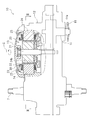
- FIG. 2 is a plan view showing a part of the drive device in a broken manner.
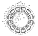
- FIG. 3 is a cross-sectional view taken along the line III-III of FIG. 2 of the stator and the spacer of the motor according to the first embodiment.
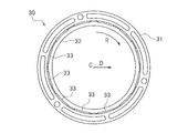
- FIG. 4 is a perspective view of the spacer.
- FIG. 5 is a plan view of the spacer.
- FIG. 6 is a side view of the spacer.
- FIG. 7 is a back view of the spacer.
- FIG. 8 is an enlarged sectional view of a part of the stator and the spacer.
- FIG. 9 is an enlarged sectional view of a part of a stator and a spacer of a motor according to a modification.
- FIG. 10 is an enlarged sectional view of a part of a stator and a spacer of a motor according to another modification.
- FIG. 11 is a perspective view of the
- the electric bicycle 1 is supported by a vehicle body frame 2, front wheels 3 and rear wheels 4 rotatably supported by the vehicle body frame 2, and the vehicle body frame 2.
- a steering wheel 5 for steering the front wheel 3, a saddle 6 supported by the vehicle body frame 2, on which a passenger (not shown) sits, and a drive device 10 supported by the vehicle body frame 2 are provided.
- the rear wheel 4 is a drive wheel driven by the drive device 10.
- the driving device 10 is provided with a horizontally extending crankshaft 7.
- the pedals 8 are connected to both ends of the crankshaft 7.
- the crankshaft 7 is rotated by the force of stepping on the pedal 8.
- the power of the crankshaft 7 is transmitted to the rear wheel 4 via the chain 9.
- a battery 11 is supported on the vehicle body frame 2.
- the drive device 10 is driven by a housing 12, a cover 13 attached to the housing 12, a brushless motor (hereinafter simply referred to as a motor) 20 disposed inside the housing 12, and a motor 20. And an output shaft 14.
- the tip 14 a of the output shaft 14 is disposed outside the housing 12.
- the sprocket 15 in which the chain 9 (refer FIG. 1) was wound is being fixed to the front-end
- the motor 20 is driven by the battery 11.
- the motor 20 generates an auxiliary power corresponding to the pedaling force on the pedal 8.
- the stepping force on the pedal 8 and the power generated by the motor 20 are transmitted to the chain 9 via the crankshaft 7 and the output shaft 14 respectively.
- the chain 9 combines these treading power and power and transmits it to the rear wheel 4.
- the electric bicycle 1 travels.
- the motor 20 includes a rotating shaft 21, a rotor 22, a spacer 30, and a stator 23.
- the motor 20 according to the present embodiment is a so-called inner rotor type motor, and the rotor 22 is disposed inward in the radial direction of the annular stator 23.
- the rotor 22 is rotatable around the rotation center C of the rotating shaft 21.
- the rotor 22 is configured by a permanent magnet, but the configuration of the rotor 22 is not limited at all.
- the rotating shaft 21 is fixed to the rotor 22 so as to rotate with the rotor 22.
- An output shaft 14 is connected to the rotation shaft 21.
- the output shaft 14 rotates with the rotation shaft 21.
- the stator 23 is fixed to the housing 12.
- the stator 23 includes a plurality of teeth 24 and a coil 25 wound around the teeth 24.
- FIG. 3 is a cross-sectional view of the stator 23 and the spacer 30 taken along line III-III. In FIG. 3, only a part of the coil 25 is illustrated, and the other part of the coil 25 is not illustrated.
- the stator 23 has an iron core 23a and an insulator 23b. Each tooth 24 is composed of a part of the iron core 23a and a part of the insulator 23b.
- the teeth 24 are radially disposed about the rotation center C.
- Each tooth 24 has a constricted portion 24 a around which the coil 25 is wound and a tip portion 24 c having an opposing surface 24 b facing the rotor 22.
- the constricted portion 24a and the tip portion 24c have the iron core 23a and the insulator 23b disposed to the side of the iron core 23a, but the insulator 23b is not provided on the opposing surface 24b of the tip portion 24c.
- the width Wc of the tip portion 24c in the circumferential direction R is larger than the width Wa of the neck portion 24a in the circumferential direction R.
- the tip portions 24c of the teeth 24 adjacent to each other are separated in the circumferential direction R. Slots 26 in which the coils 25 are accommodated are formed between the adjacent teeth 24.
- FIG. 4 is a perspective view of the spacer 30.
- FIG. 5, 6 and 7 are a plan view, a side view and a back view of the spacer 30, respectively.
- the spacer 30 comprises a first annular member 31, a second annular member 32, and a plurality of closure members 33.
- Each closing member 33 is formed in a plate shape.
- Each closing member 33 has a first end 33 a and a second end 33 b at both ends in the axial direction of the rotation shaft 21.
- the first annular member 31 and the second annular member are annularly formed around the rotation center C.
- the first annular member 31 connects the first ends 33 a of the closing member 33 to each other.
- the second annular member 32 connects the second ends 33 b of the closing member 33 to each other.
- An opening 34 is formed between the adjacent closing members 33.
- the opening 34 is a through hole formed by the first annular member 31, the second annular member 32, and the closing member 33.
- a rib 35 is formed on an outer portion of the closing member 33 in the radial direction D.
- the rib 35 protrudes outward in the radial direction D.
- the rotor 22 is disposed inward in the radial direction D of the closing member 33.
- the rib 35 is formed on the side of the closing member 33 opposite to the rotor 22.
- the rib 35 is inclined inward in the radial direction D from the first end 33 a to the second end 33 b of the closing member 33.
- the rib 35 is inclined toward the rotor 22 from the first end 33 a to the second end 33 b of the closing member 33.
- the outer diameter of the first annular member 31 is larger than the outer diameter of the second annular member 32.
- the first annular member 31, the closing member 33, and the second annular member 32 are integrally formed of a resin material.
- the spacer 30 is integrally formed of a resin material.
- resin material PBT, PPS etc. can be used, for example.
- LCP Liquid Crystal Polymer
- the resin material is not particularly limited.
- the first annular member 31, the closing member 33, and the second annular member 32 can be formed of a material other than a resin material. Any material suitable as a nonmagnetic material can be used.
- the spacer 30 is engaged with the stator 23.
- the spacer 30 is attached to the stator 23 such that the closing member 33 is fitted between the tip portions 24 c of the teeth 24.
- the tip 24 c of the tooth 24 is fitted in the opening 34 (see FIG. 4) of the spacer 30.
- the opposing surface 24 b of the teeth 24 is exposed toward the rotor 22.
- the spacer 30 is not interposed between the facing surface 24 b of the teeth 24 and the rotor 22.
- the opposing surface 24b of the teeth 24 and the rotor 22 directly oppose each other without intervening members.
- the tip 24 c of the tooth 24 has a side surface 24 d facing the closing member 33.
- the closing member 33 is in contact with at least a part of the side surface 24d. There is no gap through which the wind passes between the tip 24 c of the tooth 24 and the closing member 33.
- the distal end portion 24 c of the tooth 24 has a side surface 24 d opposite to the side surface 33 c of the closing member 33.
- the side surface 24 d and the side surface 33 c are flat surfaces. Therefore, the closing member 33 is in surface contact with at least a part of the side surface 24d.
- the closing member 33 is in surface contact with the entire side surface 24d.
- the closing member 33 is not in contact with the constricted portion 24 a of the tooth 24.
- the rib 35 is disposed radially outward of the tip 24 c of the tooth 24.
- the closing member 33 has a major surface 33 d facing the rotor 22.
- the main surface 33 d of the closing member 33 is flush with the facing surface 24 b of the tooth 24 in the circumferential direction R.
- “being flush with the circumferential direction R” means that there is substantially no step in the radial direction between the major surface 33 d of the closing member 33 and the opposing surface 24 b of the teeth 24.
- the facing surface 24b of the teeth 24 and the main surface 33d of the closing member 33 are flat surfaces, but the facing surface 24b of the teeth 24 and / or the main surface 33d of the closing member 33 may be curved Good.
- the ribs 35 of the spacer 30 are inclined inward in the radial direction D from the first end 33 a to the second end 33 b of the closing member 33. Therefore, the second end 33b of each closing member 33 is disposed between the end portions 24c of the teeth 24, and the spacer 30 is pushed axially toward the stator 23 to slide the spacer 30 against the stator 23 It can be moved. Thus, the spacer 30 can be press-fit into the stator 23, and the spacer 30 can be easily attached to the stator 23.
- the above is the configuration of the motor 20.
- the rotor 22 rotates inward of the stator 23.
- an air flow is generated between the rotor 22 and the stator 23.
- the closing member 33 of the spacer 30 is disposed between the tip portions 24 c of the adjacent teeth 24. Therefore, the air flow passing between the adjacent teeth 24 is not generated.
- the closing member 33 of the spacer 30 is disposed between the tip portions 24 c of the adjacent teeth 24. Therefore, the swing of the tip 24 c of the tooth 24 is suppressed by the closing member 33. Therefore, according to the motor 20, the generation of abnormal noise is suppressed.
- the opposing surface 24b of the teeth 24 is exposed toward the rotor 22, although the spacer 30 is arrange
- the closing member 33 is connected by the first annular member 31 and the second annular member 32, the strength of the spacer 30 can be improved. Since deformation and positional deviation of the spacer 30 are suppressed when the rotor 22 rotates, the generation of abnormal noise can be further suppressed.
- the strength of the spacer 30 can be improved.
- the first annular member 31, the closing member 33, and the second annular member 32 are formed of a resin material, they can be easily integrally molded.
- the spacer 30 is provided with the rib 35 formed on the side of the closing member 33 opposite to the rotor 22.
- This rib 35 makes it possible to increase the strength of the closing member 33 and thus to improve the overall strength of the spacer 30. Since the rib 35 is formed on the side of the closing member 33 opposite to the rotor 22, it is not necessary to increase the distance between the facing surface 24 b of the tooth 24 and the rotor 22 in order to arrange the rib 35. Therefore, the original performance of the motor 20 can be secured.
- the rib 35 is inclined toward the rotor 22 from the first end 33 a to the second end 33 b of the closing member 33.
- the teeth 30 are positioned by positioning the closing member 33 between the tips 24 c of the teeth 24 and sliding the spacer 30 along the axial direction of the closing member 33 from the second end 33 b. Can be inserted into Therefore, the spacer 30 can be easily attached to the teeth 24.
- the rib 35 can be used as a member for assisting the attachment of the spacer 30.
- the rib 35 is inclined toward the rotor 22 from the first end 33a to the second end 33b of the closing member 33.
- the rib 35 is inclined from the second end 33b to the second end 33b. It may be inclined toward the rotor 22 as it goes to the one end 33a.
- the closing member 33 of the spacer 30 is in contact with at least a part of the side surface 24d of the tip 24c of the tooth 24, the closing member 33 and the tip 24c of the tooth 24 Airflow can be sufficiently suppressed between the two.
- positional deviation of the closing member 33 at the time of rotation of the rotor 22 can be suppressed.
- the generation of abnormal noise can be suppressed more reliably.
- the main surface 33 d of the closing member 33 of the spacer 30 and the opposing surface 24 b of the teeth 24 are flush with each other in the circumferential direction R.
- the main surface 33 d of the closing member 33 of the spacer 30 and the opposing surface 24 b of the teeth 24 are flush with each other in the circumferential direction R, but as shown in FIG. You may make it be located in the direction of the rotor 22 rather than the opposing surface 24b of the teeth 24. Thereby, the closing member 33 is disposed closer to the tip 24 c of the tooth 24. As a result, since the number of turns of the coil 25 can be increased, the output of the motor 20 can be increased.
- the main surface 33 d of the spacer 30 may be located opposite to the rotor 22 than the facing surface 24 b of the teeth 24. It is necessary to provide a certain distance between the major surface 33 d of the spacer 30 and the rotor 22 in consideration of the manufacturing error of the spacer 30. According to the structure shown in FIG. 10, since the opposing surface 24b of the teeth 24 is located in the direction of the rotor 22 rather than the main surface 33d of the closing member 33 of the spacer 30, the distance between the teeth 24 and the rotor 22 It can be kept small. Thus, the output of the motor 20 can be increased.
- the spacer 30 is integrally formed and is a single member.
- the spacer 30 may consist of two members.
- the closure member 33 comprises a first part connected to the first annular member 31 and a second part connected to the second annular member 32, and the first part of the first annular member 31 and the first part of the closure member 33
- the second annular member 32 and the second portion of the closing member 33 may constitute a second member.
- the closing member 33 may be constituted by the axially separable first and second members.
- the first portion of the closing member 33 is inclined toward the rotor 22 as it is farther from the first annular member 31, and the second portion of the closing member 33 is closer to the rotor 22 as it is farther from the second annular member 32. It may be inclined toward the Thus, the first member can be easily inserted into the stator 23 toward the second member, and the second member can be easily inserted into the stator 23 toward the first member.
- the motor 20 according to the first embodiment is an inner rotor type motor
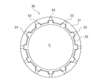
- the motor 20 according to the second embodiment shown in FIG. 11 is an outer rotor type motor.
- the same parts as those in the first embodiment are denoted by the same reference numerals, and detailed descriptions thereof will be omitted.
- the motor 20 also includes a rotor 22 that can rotate around a rotation center C, a stator 23 disposed concentrically with the rotor 22, and a spacer 30.
- the stator 23 and the spacer 30 are disposed inward of the rotor 22.
- the stator 23 includes a plurality of teeth 24 radially disposed about the rotation center C, and a coil 25 wound around the teeth 24.
- the coil 25 is simplified and shown in figure.
- the teeth 24 extend inward in the radial direction, but in the second embodiment, the teeth 24 extend outward in the radial direction.
- the teeth 24 have a neck 24 a around which the coil 25 is wound, and a tip 24 c having an opposite surface 24 b facing the rotor 22 and wider than the neck 24 a.
- the tip portions 24c of the teeth 24 adjacent to each other are separated in the circumferential direction R.
- the spacer 30 has a plurality of closing members 33 disposed between the tips 24 c of the adjacent teeth 24, and is attached to the teeth 24 such that the facing surfaces 24 b of the teeth 24 are exposed toward the rotor 22. There is.
- the first ends 33 a of the closing member 33 are connected by a first annular member 31, and the second ends 33 b are connected by a second annular member 32.
Landscapes
- Engineering & Computer Science (AREA)
- Power Engineering (AREA)
- Chemical & Material Sciences (AREA)
- Combustion & Propulsion (AREA)
- Transportation (AREA)
- Mechanical Engineering (AREA)
- Motor Or Generator Frames (AREA)
- Iron Core Of Rotating Electric Machines (AREA)
- Electric Propulsion And Braking For Vehicles (AREA)
- Insulation, Fastening Of Motor, Generator Windings (AREA)
Abstract
Description
図1に示すように、本発明の一実施形態に係る電動自転車1は、車体フレーム2と、車体フレーム2に回転可能に支持された前輪3および後輪4と、車体フレーム2に支持され、前輪3を操舵するハンドル5と、車体フレーム2に支持され、図示しない乗員が座るサドル6と、車体フレーム2に支持された駆動装置10とを備えている。後輪4は駆動装置10によって駆動される駆動輪である。駆動装置10には、水平に延びるクランク軸7が設けられている。クランク軸7の両端には、ペダル8が連結されている。ペダル8を踏む力によってクランク軸7は回転する。クランク軸7の動力はチェーン9を介して後輪4に伝達される。車体フレーム2にはバッテリー11が支持されている。
上記実施形態では、スペーサ30の閉鎖部材33の主面33dとティース24の対向面24bとは周方向Rに面一に並んでいたが、図9に示すように、スペーサ30の主面33dがティース24の対向面24bよりもロータ22の方に位置するようにしてもよい。これにより、閉鎖部材33は、よりティース24の先端部24cの方に配置される。その結果、コイル25の巻き数を増やすことができるので、モータ20の出力を増加させることができる。
第1実施形態に係るモータ20はインナーロータ型のモータであったが、ステータが環状のロータの径方向の内方に配置されたアウターロータ型のモータに本発明を適用することも可能である。図11に示す第2実施形態に係るモータ20は、アウターロータ型のモータである。以下の説明では、第1実施形態と同様の部分には同様の符号を付し、それらの詳しい説明は省略することとする。
22 ロータ
23 ステータ
24 ティース
24a くびれ部
24b 対向面
24c 先端部
25 コイル
30 スペーサ
33 閉鎖部材
C 回転中心
Claims (13)
- 回転中心を中心として回転可能なロータと、
前記回転中心を中心として放射状に配置された複数のティースと、前記ティースに巻かれたコイルと、を有し、前記ロータと同心円状に配置されたステータと、を備え、
前記各ティースは、前記コイルが巻かれるくびれ部と、前記ロータに対向する対向面を有しかつ前記くびれ部よりも幅が大きい先端部とを備え、
隣り合うティースの前記先端部同士は周方向に離間しており、
隣り合うティースの前記先端部の間に配置された複数の閉鎖部材を有し、前記各ティースの前記対向面が前記ロータに向かって露出するように前記ティースに取り付けられるスペーサを備えた、ブラシレスモータ。 - 前記各閉鎖部材は、第1端部および第2端部を有する板状に形成されており、
前記スペーサは、前記回転中心を中心として環状に形成され、前記閉鎖部材の前記第1端部同士をつなぐ第1環状部材と、前記回転中心を中心として環状に形成され、前記閉鎖部材の前記第2端部同士をつなぐ第2環状部材と、を備え、
前記スペーサの隣り合う閉鎖部材同士の間に、前記ティースの前記先端部が嵌まり込む開口が形成されている、請求項1に記載のブラシレスモータ。 - 前記スペーサの前記第1環状部材、前記閉鎖部材、および前記第2環状部材は、樹脂材料により一体成形されている、請求項2に記載のブラシレスモータ。
- 前記スペーサは、前記閉鎖部材のうち前記ロータと反対の側に形成されたリブを備えている、請求項2または3に記載のブラシレスモータ。
- 前記リブは、前記第1端部から前記第2端部に行くほど前記ロータの方に向かうように、または、前記第2端部から前記第1端部に行くほど前記ロータの方に向かうように傾斜している、請求項4に記載のブラシレスモータ。
- 前記ティースの前記先端部は、前記スペーサの前記閉鎖部材と対向する側面を有し、
前記スペーサの前記閉鎖部材は、前記ティースの前記先端部の前記側面の少なくとも一部と接触している、請求項1~5のいずれか一つに記載のブラシレスモータ。 - 前記スペーサの前記閉鎖部材は、LCPからなっている、請求項1~6のいずれか一つに記載のブラシレスモータ。
- 前記スペーサの前記閉鎖部材は、前記ロータと対向する主面を有し、
前記閉鎖部材の前記主面は、前記ティースの前記対向面と周方向に面一に並んでいる、請求項1~7のいずれか一つに記載のブラシレスモータ。 - 前記スペーサの前記閉鎖部材は、前記ロータと対向する主面を有し、
前記閉鎖部材の前記主面は、前記ティースの前記対向面よりも前記ロータの方に位置している、請求項1~7のいずれか一つに記載のブラシレスモータ。 - 前記スペーサの前記閉鎖部材は、前記ロータと対向する主面を有し、
前記閉鎖部材の前記主面は、前記ティースの前記対向面よりも前記ロータと反対の方に位置している、請求項1~7のいずれか一つに記載のブラシレスモータ。 - 前記ステータは環状に形成され、
前記ロータは、前記ステータの径方向の内方に配置されている、請求項1~10のいずれか一つに記載のブラシレスモータ。 - 前記ロータは環状に形成され、
前記ステータは、前記ロータの径方向の内方に配置されている、請求項1~10のいずれか一つに記載のブラシレスモータ。 - 請求項1~12のいずれか一つに記載のブラシレスモータと、
前記ブラシレスモータによって駆動される駆動輪と、
を備えた電動自転車。
Priority Applications (5)
| Application Number | Priority Date | Filing Date | Title |
|---|---|---|---|
| US15/551,319 US10840762B2 (en) | 2015-02-27 | 2015-10-15 | Brushless motor and electric bicycle provided with the same |
| AU2015384380A AU2015384380B2 (en) | 2015-02-27 | 2015-10-15 | Brushless motor and electric bicycle provided with same |
| CA2977748A CA2977748C (en) | 2015-02-27 | 2015-10-15 | Brushless motor and electric bicycle provided with the same |
| CN201580076949.2A CN107251375B (zh) | 2015-02-27 | 2015-10-15 | 无刷电机和具有该无刷电机的电动自行车 |
| EP15883307.9A EP3264572B1 (en) | 2015-02-27 | 2015-10-15 | Brushless motor and electric bicycle provided with same |
Applications Claiming Priority (2)
| Application Number | Priority Date | Filing Date | Title |
|---|---|---|---|
| JP2015038558A JP5993971B2 (ja) | 2015-02-27 | 2015-02-27 | ブラシレスモータおよびそれを備えた電動自転車 |
| JP2015-038558 | 2015-02-27 |
Publications (1)
| Publication Number | Publication Date |
|---|---|
| WO2016136017A1 true WO2016136017A1 (ja) | 2016-09-01 |
Family
ID=56788101
Family Applications (1)
| Application Number | Title | Priority Date | Filing Date |
|---|---|---|---|
| PCT/JP2015/079190 Ceased WO2016136017A1 (ja) | 2015-02-27 | 2015-10-15 | ブラシレスモータおよびそれを備えた電動自転車 |
Country Status (8)
| Country | Link |
|---|---|
| US (1) | US10840762B2 (ja) |
| EP (1) | EP3264572B1 (ja) |
| JP (1) | JP5993971B2 (ja) |
| CN (1) | CN107251375B (ja) |
| AU (1) | AU2015384380B2 (ja) |
| CA (1) | CA2977748C (ja) |
| TW (1) | TWI674732B (ja) |
| WO (1) | WO2016136017A1 (ja) |
Families Citing this family (4)
| Publication number | Priority date | Publication date | Assignee | Title |
|---|---|---|---|---|
| JP7092477B2 (ja) * | 2017-09-12 | 2022-06-28 | 株式会社Soken | 回転電機ステータ |
| CN107742928B (zh) * | 2017-11-22 | 2022-01-14 | 珠海格力电器股份有限公司 | 定子铁芯组件、电机、压缩机和空调器 |
| EP3654497B1 (en) | 2018-11-15 | 2026-04-08 | Black & Decker Inc. | Winding retention insert for a brushless motor |
| EP4002650A4 (de) * | 2019-07-17 | 2023-04-12 | Schaeffler Technologies AG & Co. KG | Statoranordnung und stator für einen motor |
Citations (4)
| Publication number | Priority date | Publication date | Assignee | Title |
|---|---|---|---|---|
| JP2003047188A (ja) * | 2001-07-27 | 2003-02-14 | Aichi Elec Co | 電動機の固定子 |
| JP2004201446A (ja) * | 2002-12-19 | 2004-07-15 | Aisin Aw Co Ltd | ステータコア用のウェッジ |
| JP2006191788A (ja) * | 2004-11-22 | 2006-07-20 | Minebea Co Ltd | 電気機械のステータ構造及びその製造方法、並びに、直流モータ |
| JP2009284641A (ja) * | 2008-05-21 | 2009-12-03 | Sanyo Denki Co Ltd | 回転電機用ステータ |
Family Cites Families (11)
| Publication number | Priority date | Publication date | Assignee | Title |
|---|---|---|---|---|
| US3489938A (en) | 1969-01-13 | 1970-01-13 | Kinzo Nakamura | Coil retainer for an iron core of rotary machines of the laminated iron core type |
| JPS5316803U (ja) | 1976-07-23 | 1978-02-13 | ||
| JP2002112473A (ja) * | 2000-10-02 | 2002-04-12 | Matsushita Electric Ind Co Ltd | 電動機及びそれを用いた密閉型圧縮機 |
| EP1670121B2 (de) | 2004-11-22 | 2012-04-04 | MINEBEA Co., Ltd. | Elektrische Maschine, insbesondere bürstenloser Gleichstrommotor |
| KR101095556B1 (ko) * | 2005-06-13 | 2011-12-19 | 삼성전자주식회사 | 영구자석 전동기 |
| TW200822488A (en) | 2006-09-08 | 2008-05-16 | Sanyo Electric Co | Motor |
| WO2010148472A1 (en) * | 2009-06-23 | 2010-12-29 | Odomotion Inc. | Axial-flux brushless electric motor |
| JP5603809B2 (ja) | 2011-03-09 | 2014-10-08 | ヤマハモーターエレクトロニクス株式会社 | ステータの固定構造および駆動装置 |
| GB2509738A (en) * | 2013-01-11 | 2014-07-16 | Rolls Royce Plc | Integral slot wedges and stator sleeve |
| JP5939446B2 (ja) * | 2013-03-29 | 2016-06-22 | 株式会社デンソー | 固定子及びその固定子を備えた回転電機並びにその固定子の製造方法 |
| US9431863B2 (en) * | 2013-07-29 | 2016-08-30 | Remy Technologies, Llc | Insulation component for an electric machine and method of assembly |
-
2015
- 2015-02-27 JP JP2015038558A patent/JP5993971B2/ja active Active
- 2015-10-15 EP EP15883307.9A patent/EP3264572B1/en active Active
- 2015-10-15 US US15/551,319 patent/US10840762B2/en active Active
- 2015-10-15 AU AU2015384380A patent/AU2015384380B2/en not_active Ceased
- 2015-10-15 WO PCT/JP2015/079190 patent/WO2016136017A1/ja not_active Ceased
- 2015-10-15 CN CN201580076949.2A patent/CN107251375B/zh active Active
- 2015-10-15 CA CA2977748A patent/CA2977748C/en active Active
- 2015-11-02 TW TW104136059A patent/TWI674732B/zh active
Patent Citations (4)
| Publication number | Priority date | Publication date | Assignee | Title |
|---|---|---|---|---|
| JP2003047188A (ja) * | 2001-07-27 | 2003-02-14 | Aichi Elec Co | 電動機の固定子 |
| JP2004201446A (ja) * | 2002-12-19 | 2004-07-15 | Aisin Aw Co Ltd | ステータコア用のウェッジ |
| JP2006191788A (ja) * | 2004-11-22 | 2006-07-20 | Minebea Co Ltd | 電気機械のステータ構造及びその製造方法、並びに、直流モータ |
| JP2009284641A (ja) * | 2008-05-21 | 2009-12-03 | Sanyo Denki Co Ltd | 回転電機用ステータ |
Non-Patent Citations (1)
| Title |
|---|
| See also references of EP3264572A4 * |
Also Published As
| Publication number | Publication date |
|---|---|
| AU2015384380A1 (en) | 2017-08-03 |
| EP3264572A4 (en) | 2018-03-07 |
| JP5993971B2 (ja) | 2016-09-21 |
| TW201631866A (zh) | 2016-09-01 |
| CA2977748C (en) | 2020-12-15 |
| TWI674732B (zh) | 2019-10-11 |
| CN107251375B (zh) | 2020-03-13 |
| JP2016163394A (ja) | 2016-09-05 |
| EP3264572A1 (en) | 2018-01-03 |
| US20180034338A1 (en) | 2018-02-01 |
| AU2015384380B2 (en) | 2020-01-30 |
| US10840762B2 (en) | 2020-11-17 |
| CA2977748A1 (en) | 2016-09-01 |
| CN107251375A (zh) | 2017-10-13 |
| EP3264572B1 (en) | 2019-12-11 |
Similar Documents
| Publication | Publication Date | Title |
|---|---|---|
| JP2010525774A (ja) | 同心円状に配置された回転子を有するモータ及び前記モータを備える駆動装置 | |
| US9793768B2 (en) | Rotor and rotary electric machine having the same | |
| ATE521125T1 (de) | Motor mit axialspalt | |
| JP7324664B2 (ja) | ドライブユニット | |
| CN103795166A (zh) | 转子和具有该转子的旋转电机 | |
| CN102447319A (zh) | Eps电机定子的分裂芯 | |
| JP5993971B2 (ja) | ブラシレスモータおよびそれを備えた電動自転車 | |
| JPWO2019066003A1 (ja) | ロータ、スポーク型モータ、車両用モータ、無人飛行体、電動アシスト装置およびロボット装置 | |
| WO2018180038A1 (ja) | モータ及び電動パワーステアリング装置 | |
| JP2014092446A (ja) | トルクセンサ、駆動ユニットおよび電動アシスト自転車 | |
| JP7163926B2 (ja) | ロータ、スポーク型モータ、車両用モータ、無人飛行体、電動アシスト装置およびロボット装置 | |
| CN106464044A (zh) | 开关磁阻电机 | |
| WO2012014969A1 (ja) | モールドモータ及びこれを搭載した移動体 | |
| CN114868322A (zh) | 电动机及具有该电动机的车辆用动力装置、发电机及具有该发电机的带有发电机的车轮用轴承 | |
| JP4682045B2 (ja) | 電動車両用のインホイールモータ | |
| TWI844667B (zh) | 人力驅動車用之輪轂 | |
| JP6445350B2 (ja) | 自転車用発電機 | |
| JP2012039714A (ja) | ハウジングリング、及びモータ、並びに電動パワーステアリング装置 | |
| JPWO2022195804A5 (ja) | ||
| JP4396227B2 (ja) | インホイールモータ | |
| JP2011152868A (ja) | ハブダイナモ | |
| JP2014057456A (ja) | 電動モータのロータ | |
| US20230112429A1 (en) | Rotor and motor including same | |
| JP5990918B2 (ja) | 電動モータ | |
| EP3629456B1 (en) | Rotor and method for manufacturing a rotor of an electric motor |
Legal Events
| Date | Code | Title | Description |
|---|---|---|---|
| 121 | Ep: the epo has been informed by wipo that ep was designated in this application |
Ref document number: 15883307 Country of ref document: EP Kind code of ref document: A1 |
|
| ENP | Entry into the national phase |
Ref document number: 2015384380 Country of ref document: AU Date of ref document: 20151015 Kind code of ref document: A |
|
| REEP | Request for entry into the european phase |
Ref document number: 2015883307 Country of ref document: EP |
|
| ENP | Entry into the national phase |
Ref document number: 2977748 Country of ref document: CA |
|
| NENP | Non-entry into the national phase |
Ref country code: DE |