WO2016132780A1 - エアバッグ装置 - Google Patents
エアバッグ装置 Download PDFInfo
- Publication number
- WO2016132780A1 WO2016132780A1 PCT/JP2016/050920 JP2016050920W WO2016132780A1 WO 2016132780 A1 WO2016132780 A1 WO 2016132780A1 JP 2016050920 W JP2016050920 W JP 2016050920W WO 2016132780 A1 WO2016132780 A1 WO 2016132780A1
- Authority
- WO
- WIPO (PCT)
- Prior art keywords
- sewing
- cushion
- reinforcing
- airbag device
- cloths
- Prior art date
- Legal status (The legal status is an assumption and is not a legal conclusion. Google has not performed a legal analysis and makes no representation as to the accuracy of the status listed.)
- Ceased
Links
Images



Classifications
-
- B—PERFORMING OPERATIONS; TRANSPORTING
- B60—VEHICLES IN GENERAL
- B60R—VEHICLES, VEHICLE FITTINGS, OR VEHICLE PARTS, NOT OTHERWISE PROVIDED FOR
- B60R21/00—Arrangements or fittings on vehicles for protecting or preventing injuries to occupants or pedestrians in case of accidents or other traffic risks
- B60R21/02—Occupant safety arrangements or fittings, e.g. crash pads
- B60R21/16—Inflatable occupant restraints or confinements designed to inflate upon impact or impending impact, e.g. air bags
- B60R21/20—Arrangements for storing inflatable members in their non-use or deflated condition; Arrangement or mounting of air bag modules or components
- B60R21/207—Arrangements for storing inflatable members in their non-use or deflated condition; Arrangement or mounting of air bag modules or components in vehicle seats
-
- B—PERFORMING OPERATIONS; TRANSPORTING
- B60—VEHICLES IN GENERAL
- B60R—VEHICLES, VEHICLE FITTINGS, OR VEHICLE PARTS, NOT OTHERWISE PROVIDED FOR
- B60R21/00—Arrangements or fittings on vehicles for protecting or preventing injuries to occupants or pedestrians in case of accidents or other traffic risks
- B60R21/02—Occupant safety arrangements or fittings, e.g. crash pads
- B60R21/16—Inflatable occupant restraints or confinements designed to inflate upon impact or impending impact, e.g. air bags
- B60R21/23—Inflatable members
- B60R21/231—Inflatable members characterised by their shape, construction or spatial configuration
Definitions
- the present invention relates to an airbag device that inflates and deploys between an occupant and a side wall portion in a vehicle compartment to restrain the occupant when an impact occurs on the vehicle.
- the airbag device is a safety device that operates in an emergency such as a vehicle collision, and mainly includes a cushion and an inflator.
- the cushion is formed by sewing the base fabric into a bag shape, and inflates and deploys with the gas pressure from the inflator, which is a gas generator, to receive and protect the occupant.
- a front airbag is provided in the center of the steering wheel in order to protect the driver from collisions in the front-rear direction.
- curtain airbags that inflate and deploy along the side windows near the ceiling of the side wall of the vehicle body, and sideways of passengers from the side of the seat Side airbags that inflate and deploy are provided.
- the cushions of the various airbag devices described above are formed in various shapes by providing sewing locations and the like in consideration of the installation location and the ease of gas inflow. These cushions need to be inflated and deployed at a rapid speed in milliseconds from the occurrence of an impact, and the internal pressure increases instantaneously. At that time, a corresponding load is applied to the sewing location of the base fabric and other joints.
- a reinforcing cloth is additionally provided at the sewing location of the base fabric, thereby increasing durability against heat and pressure near the sewing location.
- the first largest load such as heat or pressure due to gas may be applied to a place where the reinforcing cloth is added to the base cloth.
- the sewing site between the base fabric and the reinforcing fabric could not withstand the load and was cut, there was a problem that a hole opened in the base fabric and gas leaked from the hole.
- the present invention has been made in view of such a problem, and an object of the present invention is to provide an airbag device that can reduce gas leakage during inflation and deployment of a cushion.
- a typical configuration of an airbag device includes a cushion that is formed into a bag shape by sewing edges of the overlapped base fabrics, and a cushion that is formed inside the cushion. At least two reinforcing cloths that overlap the edges of the cloth to reinforce the edges, a first sewing part that sews at least two reinforcing cloths together with the edges of the base cloth, and at least two inside the cushion from the first sewing part.
- a second sewing part for sewing at least one of the reinforcing cloths with one of the overlaid base cloths, and sewing the remaining of the at least two reinforcing cloths with the other of the overlaid base cloths;
- a third sewing portion which is located between the first sewing portion and the second sewing portion and sews at least two reinforcing cloths.
- the cushion needs to be inflated and deployed quickly using the gas supplied from the inflator, and the internal pressure may increase momentarily.
- a load such as pressure or heat is applied to the sewing portion of the cushion.
- the third sewing part receives a load first
- the second sewing part is applied with a load smaller than the initial load. If the third sewing portion is cut by the load, the first sewing portion is also loaded, but the load is smaller than the load that was initially applied to the third sewing portion. Further, the third sewing portion sews only the reinforcing cloths and does not sew the base cloth. For this reason, even if a 3rd sewing part receives load and cuts, a hole is not opened in base fabric itself. On the other hand, since the first sewing portion and the second sewing portion both sew the base fabric, a hole is opened in the base fabric if it is temporarily cut. In addition, if the 3rd sewing part does not endure with a load, a load itself will not be applied to a 1st sewing part.
- the above-mentioned third sewing part may be formed using a sewing thread having a lower tensile strength than the sewing thread of the second sewing part.
- the 3rd sewing part is good to consist of sewing with the space
- a plurality of the third sewing parts may be formed.
- the third sewing portion receives an initial large load, and the remaining third sewing portion receives a load even if the third sewing portion is temporarily cut. For this reason, the load is applied to the first sewing portion only when all the third sewing portions are cut by the load. Further, only a small load is applied to the second sewing portion. Therefore, a 1st sewing part and a 2nd sewing part can be protected more reliably.
- the at least two reinforcing cloths may be composed of two or more separate cloths. Accordingly, for example, it is possible to combine and superimpose reinforcing cloths having different tensile strengths and different seam intervals. Therefore, an optimal reinforcing cloth can be selected and combined according to the cushion.
- the above-mentioned at least two reinforcing cloths may be composed of two or more layers formed by folding one cloth.
- a reinforcing cloth having two or more layers can be formed simply by preparing a single cloth and folding it.
- the more the sheet is folded the stronger the edge of the base cloth of the cushion can be reinforced, and the gas leakage can be further reduced.
- an airbag device that can reduce gas leakage when the cushion is inflated and deployed.
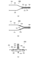
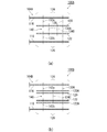
- FIG. 2 is a cross-sectional view taken along the line AA in FIG. It is a schematic diagram which shows the behavior at the time of inflation deployment of the cushion of the airbag apparatus of FIG. It is a figure which illustrates the airbag apparatus of a comparative example. It is a figure which illustrates the airbag apparatus of another comparative example. It is a figure which illustrates the airbag apparatus in other embodiment of this invention. It is a figure which illustrates the airbag apparatus in further another embodiment of this invention.
- FIG. 1 is a diagram illustrating an airbag device according to an embodiment of the present invention.
- the airbag apparatus 100 is shown as a side airbag that inflates and deploys on the side of the left seat (seat 102) of the vehicle.
- the airbag device 100 of the present invention can be realized as various airbag devices such as a front airbag and a curtain airbag in addition to the side airbag.
- the airbag device 100 includes a bag-like cushion 104 made of a base fabric and an inflator 106 that is a gas generator.
- the cushion 104 is inflated and deployed to restrain the occupant 110 by the pressure of gas supplied from the inflator 106 in an emergency such as when an impact occurs on the vehicle.
- the cushion 104 is inflated and deployed in a flat shape between the occupant 110 and, for example, a side door (not shown).
- the cushion 104 is formed into a bag shape by overlapping a plurality of base fabrics constituting the surface and sewing the edges of the overlapped base fabrics (described later). Although not shown, the cushion may be formed into a bag shape by folding a single base fabric and sewing the edges together.
- the cushion 104 is wound or folded and housed in a housing (not shown) provided on the side portion of the seat back 112. Since the cushion 104 is covered with a seat cover or the like when stored, the cushion 104 cannot be visually recognized from the outside, and when deployed, the seat cover or the like is cleaved and inflated and deployed to the side of the occupant.
- the inflator 106 employed in this embodiment is a cylinder type (tubular type).
- the inflator 106 includes a stud bolt 114.
- the stud bolt 114 is exposed from the inside of the cushion 104 and fastened to a housing or the like on the side portion of the seat back 112.
- Inflators that are currently popular are types that are filled with a gas generating agent and burn it to generate gas, types that are filled with compressed gas and supply gas without generating heat, and There are types including both a gas generating agent and a compressed gas. Any type can be used as the inflator 106 of the present embodiment.
- the cushion 104 needs to be rapidly inflated and deployed using the gas supplied from the inflator 106 in order to receive the occupant 110 in an emergency. For this reason, the internal pressure of the cushion 104 increases instantaneously, and a load such as pressure or heat is applied to each sewing location on the sewing line, for example. If such a load is applied excessively, a gap in the sewing line is opened, gas leakage occurs, and the internal pressure of the cushion 104 is reduced, which may affect the occupant restraint performance.
- a load such as pressure or heat
- FIG. 2 is a cross-sectional view taken along the line AA in FIG. In the drawing, the inside of the cushion 104 is schematically shown.
- the cushion 104 is formed into a bag shape by sewing the edges 124 and 126 of the two overlapped base fabrics 116 and 118 together.
- the two reinforcing cloths 120 and 122 are separate belt-like cloths, and are superposed on the edges 124 and 126 of the base cloths 116 and 118 inside the cushion 104 to reinforce the edges 124 and 126.
- the first sewing portion 130 sews the two reinforcing cloths 120 and 122 together with the edges 124 and 126 of the base cloths 116 and 118.
- the second sewing part 132a sews the reinforcing cloth 120 with the one base cloth 116 that is overlapped inside the cushion 104 from the first sewing part 130.
- the second sewing portion 132b sews the remaining reinforcing fabric 122 with the other base fabric 118 that is overlapped inside the cushion 104 from the first sewing portion 130.
- the third sewing part 134 is located between the first sewing part 130 and the second sewing parts 132a and 132b, and sews only the two reinforcing cloths 120 and 122.
- the second sewing portions 132a and 132b are not sewn between the reinforcing cloth 120 sewn with the base cloth 116 and the reinforcing cloth 122 sewn with the base cloth 118.
- the reinforcing cloths 120 and 122 have end portions 121 and 123, respectively, in the inner direction of the cushion 104 of the second sewing portions 132a and 132b. For this reason, an opening 140 opened in the inner direction of the cushion 104 is formed between the end portions 121 and 123 of the reinforcing cloths 120 and 122.
- FIG. 3 is a schematic diagram showing the behavior of the airbag device 100 of FIG. 1 when the cushion 104 is inflated and deployed.
- Arrow B in the figure indicates the gas supplied from the inflator 106.
- the first largest load such as heat or pressure due to the gas B passes through the opening 140 between the reinforcing cloths 120 and 122 as shown in FIG.
- a large load due to the gas B is applied to the third sewing portion 134 located between the first sewing portion 130 and the second sewing portions 132a and 132b, as shown in FIG.
- the second sewing portions 132a and 132b are applied with a load smaller than the initial load.
- the third sewing portion 134 is not able to withstand the load, the first sewing portion 130 is loaded, but the load is first applied to the third sewing portion 134. Less than the load on If the third sewing portion 134 cannot endure the load, the first sewing portion 130 is not loaded as shown in FIG. 3B.
- the third sewing portion 134 sews only the reinforcing cloths 120 and 122 and does not sew the base cloths 116 and 118. For this reason, even if the 3rd sewing part 134 receives a load and cuts, a hole is not opened in base fabric 116,118 itself.
- the first sewing portion 130 and the second sewing portions 132a and 132b both sew the base fabrics 116 and 118, if they are temporarily cut, holes are opened in the base fabrics 116 and 118, and gas leaks from the holes. There is a case.
- the third sewing portion 134 is first subjected to a load due to the gas B through the opening 140. For this reason, in this embodiment, a large load is not applied to the first sewing portion 130 and the second sewing portions 132a and 132b, these sewing locations are protected, and the base fabrics 116 and 118 are not perforated with gas. Leakage can be reduced.
- the third sewing portion 134 is formed using a sewing thread having a lower tensile strength than the sewing thread of the second sewing portions 132a and 132b, or the stitches are stitched more than the sewing of the second sewing portions 132a and 132b. What is necessary is just to form the 3rd sewing part 134 by sewing with the space
- the load concerning the 2nd sewing parts 132a and 132b becomes smaller, and can protect the 2nd sewing parts 132a and 132b reliably. Furthermore, the load applied to the first sewing portion 130 can be sufficiently reduced.
- FIG. 4 is a view illustrating an airbag device 200 of a comparative example.
- the airbag device 200 of the comparative example is not provided with the third sewing portion 134, and is provided with the reinforcing cloth 202 and does not have the opening 140. , Different from the airbag apparatus 100 described above.
- the airbag device 200 includes a first sewing portion 208 that sews the reinforcing fabric 202 together with the edges of the base fabrics 204 and 206, and second sewing portions 210a and 210b that sew the reinforcing fabric 202 and the base fabrics 204 and 206, respectively. .
- first sewing portion 208 that sews the reinforcing fabric 202 together with the edges of the base fabrics 204 and 206
- second sewing portions 210a and 210b that sew the reinforcing fabric 202 and the base fabrics 204 and 206, respectively.
- FIG. 5 is a diagram illustrating air bag devices 200A, 200B, and 200C of other comparative examples.
- the airbag device 200 ⁇ / b> A of the comparative example is such that the reinforcing fabrics 220 and 222 reinforce the edges of the base fabrics 226 and 228 outside the cushion 224. And different.
- the airbag device 200A has sewing portions 230, 232, and 234.
- the sewing parts 230 and 232 sew two reinforcing cloths 220 and 222 together with the edges of the base cloths 226 and 228.
- the sewing part 234 is located between the sewing parts 230 and 232, and only the base cloths 226 and 228 are sewn together.
- the airbag device 200B is different from the airbag device 100 in that the airbag device 200B does not have the third sewing portion 134 as shown in FIG.
- the airbag device 200 ⁇ / b> B when the cushion 236 is inflated and deployed, the first large load is applied to the first sewing portion 130. For this reason, if the 1st sewing part 130 cannot endure a load and will run out, gas leak will arise from cushion 236 itself.
- the airbag device 200 ⁇ / b> C includes two first sewing portions 240 and 242, and a second sewing portion is provided between the first sewing portions 240 and 242 and the third sewing portion 244. It differs from the airbag apparatus 100 in that 246a and 246b are located. In such an airbag device 200 ⁇ / b> C, since the reinforcing cloths 248 and 250 are sewn together by the third sewing portion 244, the opening 140 does not exist inside the cushion 252.
- the airbag device 200C As with the airbag device 200 of the comparative example illustrated in FIGS. 4B and 4C, when the cushion 252 is inflated and deployed from the actually folded state, it is reinforced by the gas pressure. The positions of the cloths 248 and 250 are offset. Therefore, in the airbag device 200C, if any of the second sewing parts 246a and 246b is initially subjected to a large load and any of the second sewing parts 246a and 246b cannot withstand the load, the base fabric 252, Gas is leaked when a hole is opened in any one of 254 or the base fabrics 252 and 254 are torn from that portion.
- FIG. 6 is a diagram illustrating airbag devices 100A and 100B according to another embodiment of the present invention.
- a plurality of (here, two) third sewing parts 134A and 134B sew only two reinforcing cloths 120 and 122, Different from the airbag device 100 described above.
- the third sewing portion 134A close to the positions of the second sewing portions 132a and 132b receives an initial large load due to gas. Even if the third sewing portion 134A is not able to withstand the load, the remaining third sewing portion 134B continues to receive the load.
- the load is applied to the first sewing portion 130 only when all the third sewing portions 134A and 134B are cut by the load. Further, only a small load is applied to the second sewing parts 132a and 132b. Therefore, according to the airbag device 100A, by forming the plurality of third sewing portions 134A and 134B, the first sewing portion 130 and the second sewing portions 132a and 132b are more reliably protected and gas leakage is reduced. it can.
- the number of the third sewing parts is not limited to two, and may be at least one.
- the airbag apparatus 100B differs from the airbag apparatus 100 in that four reinforcing cloths 120, 120A, 122, and 122A are used, as shown in FIG. 6 (b).
- the four reinforcing fabrics 120, 120A, 122, 122A are sewn together with the edges 124, 126 of the base fabrics 116, 118 at the first sewing portion 130A, and the third sewing portion 134C. Only four reinforcing cloths 120, 120A, 122, 122A are sewn together.
- the edges 124 and 126 of the base fabrics 116 and 118 are more strongly reinforced by the four reinforcing fabrics 120, 120A, 122, and 122A inside the cushion 104B. Can hardly be cut off by gas pressure, etc., and gas leakage can be reduced.
- the number of reinforcing cloths is two or four, but is not limited thereto. That is, in the second sewing portion, there is no sewing between the reinforcing cloth sewn with one base cloth 116 and the reinforcing cloth sewn with the other base cloth 118, and the opening 140 can be formed between them.
- the number of reinforcing cloths may be at least two.
- the second sewing portion at least one of the eight reinforcing cloths is sewn with one base cloth 116, and the remaining among the eight reinforcing cloths is the other base cloth 118. And may be sewn. As the number of reinforcing fabrics increases, the edges 124 and 126 of the base fabrics 116 and 118 are more strongly reinforced, and gas leakage can be reduced.
- the present invention is not limited to this, and at least two sheets of reinforcing cloth may be used as a result of folding a single cloth into two or more layers (see FIG. 7).
- the reinforcing cloth when two or more separate cloths are stacked or when one cloth is folded and overlapped into two or more layers, it is regarded as “at least two” reinforcing cloths.
- FIG. 7 is a diagram illustrating an airbag device according to still another embodiment of the present invention.
- the airbag device 100C instead of the reinforcing cloths 120 and 122 made of two separate cloths, one cloth 144 is folded back and overlapped at a folding point 146, that is, two layers. It differs from the airbag apparatus 100 in that the reinforcing cloths 120B and 122B are used.
- Such an airbag device 100C is easier to manufacture than the airbag device 100 because the two layers of reinforcing fabrics 120B and 122B can be formed inside the cushion 104C simply by preparing a single piece of fabric 144 and folding it. It becomes. Further, the first sewing portion 130B sews the reinforcing cloths 120B and 122B obtained by folding a single cloth 144 together with the base cloths 116 and 118. For this reason, in the airbag device 100C, even if a load is applied to the first sewing portion 130B, the gas is received at the folded portion 146 of the single cloth 144, and gas leakage can be further reduced.
- the reinforcing cloths 120, 120A, 122, and 122A instead of the reinforcing cloths 120, 120A, 122, and 122A (see FIG. 6B) made of four separate cloths, as shown in FIG. This is different from the airbag device 100B in that the reinforcing fabrics 120C and 122C made of are used.
- the reinforcing cloths 120C and 122C have four layers at the position of the first sewing portion 130C by folding and overlapping one piece of cloth 148 at the folding positions 150a, 150b, and 150c.
- one cloth 146 and 148 are folded to form reinforcing cloths 120B, 122B, 120C, and 122C. As the 148 is folded, the edges 124 and 126 of the base fabrics 116 and 118 of the cushions 104C and 104D can be reinforced more strongly, and gas leakage can be further reduced.
- the present invention can be used in an airbag device that restrains an occupant by inflating and deploying between the occupant and a side wall portion or the like of the passenger compartment when an impact occurs on the vehicle.
Landscapes
- Engineering & Computer Science (AREA)
- Mechanical Engineering (AREA)
- Air Bags (AREA)
Abstract
【課題】クッションの膨張展開時にガス漏れを低減できるエアバッグ装置を提供することを目的とする。 【解決手段】本発明にかかるエアバッグ装置100は、重ねられた基布116、118の縁124、126同士が縫製されることで袋状になっているクッション104と、クッションの内部で基布の縁に重ねられて縁を補強する2枚の補強布120、122と、基布の縁とともに2枚の補強布を縫製する第1縫製部130と、第1縫製部よりクッションの内側で補強布の少なくとも1枚を、重ねられた基布の一方と縫製し、補強布の残りを、重ねられた基布の他方と縫製する第2縫製部132a、132bと、第1縫製部と第2縫製部との間に位置し、2枚の補強布同士のみを縫製する第3縫製部134とを備える。
Description
本発明は、車両に衝撃が生じた場合などに、乗員と車室内の側壁部等との間に膨張展開して乗員を拘束するエアバッグ装置に関するものである。
近年の車両にはエアバッグ装置がほぼ標準装備されている。エアバッグ装置は、車両衝突などの緊急時に作動する安全装置であって、主にクッションとインフレータとから構成されている。クッションは、基布を袋状に縫製などすることで形成され、ガス発生装置であるインフレータからのガス圧で膨張展開して乗員を受け止めて保護する。
エアバッグ装置には、設置箇所や用途に応じて様々な種類がある。例えば、前後方向からの衝突から運転者を守るために、ステアリングの中央にはフロントエアバッグが設けられている。また、側面衝突やそれに続いて起こるロールオーバ(横転)から乗員を守るために、車体側壁の天井付近にはサイドウィンドウに沿って膨張展開するカーテンエアバッグや、座席の側部から乗員のすぐ脇へ膨張展開するサイドエアバッグが設けられている。
上述した各種エアバッグ装置のクッションは、設置場所やガスの流入のしやすさ等を考慮し、縫製箇所等を設けて様々な形状に形成されている。これらクッションは、衝撃発生からミリ秒単位の迅速なスピードで膨張展開する必要があり、内圧が瞬間的に高まることになる。その際、基布の縫製箇所やその他の接合部などには相応の負荷がかかる。
そこで、特許文献1に記載のエアバッグ装置では、基布の縫製箇所にさらに補強布を追加して設け、これによって縫製箇所付近の熱や圧力に対する耐久性を上げている。
特許文献1に記載のエアバッグ装置では、クッションが膨張展開した際、ガスによる熱や圧力などの最初の最も大きな負荷が、基布に補強布を追加した箇所にかかる場合がある。このような場合、基布と補強布との縫製箇所が負荷に耐えられず切れてしまうと、基布に孔が開き、孔からガスが漏れてしまうという問題があった。
本発明は、このような課題に鑑み、クッションの膨張展開時にガス漏れを低減できるエアバッグ装置を提供することを目的としている。
上記課題を解決するために、本発明にかかるエアバッグ装置の代表的な構成は、重ねられた基布の縁同士が縫製されることで袋状になっているクッションと、クッションの内部で基布の縁に重ねられて縁を補強する少なくとも2枚の補強布と、基布の縁とともに少なくとも2枚の補強布を縫製する第1縫製部と、第1縫製部よりクッションの内側で少なくとも2枚の補強布の少なくとも1枚を、重ねられた基布の一方と縫製し、少なくとも2枚の補強布の残りを、重ねられた基布の他方と縫製する第2縫製部と、第1縫製部と第2縫製部との間に位置し、少なくとも2枚の補強布同士のみを縫製する第3縫製部とを備えることを特徴とする。
ここでクッションは、インフレータから供給されるガスを利用して迅速に膨張展開する必要があり、内圧が瞬間的に高まる場合がある。この場合、クッションの縫製箇所には圧力や熱などの負荷がかかる。
上記構成では、第1縫製部よりクッションの内側に位置する第2縫製部において、基布の一方と縫製される補強布と、基布の他方と縫製される補強布との間が縫製されていず、その間にはクッションの内側方向に開いている開口が形成される。このため、クッションが膨張展開した際、ガスによる熱や圧力などの最初の最も大きな負荷は、まず開口を通して第1縫製部と第2縫製部との間に位置する第3縫製部にかかり、第1縫製部および第2縫製部にはかからない。
また第3縫製部が最初に負荷を受けるため、第2縫製部には、最初の負荷よりも小さい負荷しかかからない。仮に第3縫製部が負荷により切れると、第1縫製部にも負荷がかかるが、その負荷は最初に第3縫製部にかかった負荷よりも小さい。さらに第3縫製部は、補強布同士のみを縫製していて、基布を縫製していない。このため、第3縫製部が負荷を受けて切れたとしても、基布自体には孔が開かない。一方、第1縫製部および第2縫製部は、いずれも基布を縫製しているため、仮に切れると基布に孔が開いてしまう。なお第3縫製部が負荷に耐えて切れなければ、第1縫製部には負荷自体がかからない。
したがって上記構成によれば、クッションの膨張展開時に第1縫製部および第2縫製部に大きな負荷がかからず、これらの縫製箇所を保護し、基布に孔が開くこともなくガス漏れを低減できる。なお本願では、「少なくとも2枚」の補強布とは、2枚以上の別体の布を重ねた場合や1枚の布を折り返し重ねて2層以上にした場合を想定している。
上記の第3縫製部は、第2縫製部の縫製糸よりも引っ張り強度が低い縫製糸を用いて形成されるとよい。あるいは、第3縫製部は、第2縫製部の縫製よりも縫い目の間隔が広い縫製からなるとよい。このようにすれば、第3縫製部は、クッションの膨張展開時に負荷がかかると、第2縫製部よりも確実に先に切れることになる。よって、第2縫製部にかかる負荷をより小さくして、第2縫製部を保護できる。
上記の第3縫製部は複数形成されるとよい。これにより、クッションの膨張展開時に、第3縫製部が最初の大きな負荷を受け、仮に切れても残りの第3縫製部が負荷を受ける。このため、全ての第3縫製部が負荷により切れた場合のみ、第1縫製部に負荷がかかる。また、第2縫製部には、小さな負荷しかかからない。よって、第1縫製部と第2縫製部とをより確実に保護できる。
上記の少なくとも2枚の補強布は、2枚以上重ねられた別体の布からなるとよい。これにより、例えば引っ張り強度や縫い目の間隔が異なる補強布を組み合わせて重ねることが可能となる。よって、クッションに応じて最適な補強布を選定し組み合わせることができる。
上記の少なくとも2枚の補強布は、1枚の布を折り返して重ねられた2層以上からなるとよい。これにより、1枚の布を用意しこれを折り重ねるだけで2層以上の補強布を形成できる。また、1枚の布を折り重ねるほど、クッションの基布の縁をより強く補強でき、ガス漏れをより低減できる。
本発明によれば、クッションの膨張展開時にガス漏れを低減できるエアバッグ装置を提供することができる。
100、100A、100B、100C、100D…エアバッグ装置、102…シート、104、104A、104B、104C、104D…クッション、106…インフレータ、110…乗員、112…シートバック、114…スタッドボルト、116、118…基布、120、120A、120B、120C、122、122A、122B、122C…補強布、121、123…補強布の端部、124、126…基布の縁、130、130A、130B、130C…第1縫製部、132a、132b、142a、142b…第2縫製部、134、134A、134B、134C…第3縫製部、140…開口、144、148…1枚の布、146、150a、150b、150c…折り返し箇所
以下に添付図面を参照しながら、本発明の好適な実施形態について詳細に説明する。かかる実施形態に示す寸法、材料、その他具体的な数値などは、発明の理解を容易とするための例示に過ぎず、特に断る場合を除き、本発明を限定するものではない。なお、本明細書及び図面において、実質的に同一の機能、構成を有する要素については、同一の符号を付することにより重複説明を省略し、また本発明に直接関係のない要素は図示を省略する。
図1は、本発明の実施形態におけるエアバッグ装置を例示する図である。図中では、エアバッグ装置100を車両左側座席(シート102)の側方で膨張展開するサイドエアバッグとして示している。ただし、本発明のエアバッグ装置100は、サイドエアバッグ以外にも、フロントエアバッグやカーテンエアバッグ等の各種エアバッグ装置としても実現可能である。
エアバッグ装置100は、基布で構成された袋状のクッション104と、ガス発生装置であるインフレータ106とを備えている。クッション104は、車両に衝撃が発生した場合などの緊急時にインフレータ106から供給されるガスの圧力により、膨張展開して乗員110を拘束する。クッション104は、乗員110と例えばサイドドア(図示省略)との間で扁平な形状に膨張展開する。
クッション104は、表面を構成する複数の基布を重ねて、さらに重ねられた基布の縁同士が縫製されることで袋状になっている(後述)。なお図示しないものの、クッションは、単一の基布を折り重ねて縁同士を縫製することで袋状にしてもよい。クッション104は、シートバック112の側部に備えられた不図示のハウジングに、巻回または折り畳まれて収納されている。クッション104は、収納時にはその上をシートカバー等が覆っているため、外部からは視認不能であり、展開時にはシートカバー等を開裂させて、乗員の側方へ膨張展開する。
本実施形態で採用しているインフレータ106は、シリンダ型(筒型)のものである。インフレータ106は、スタッドボルト114を備えている。スタッドボルト114はクッション104内から露出し、シートバック112の側部のハウジング等に締結される。現在普及しているインフレータには、ガス発生剤が充填されていてこれを燃焼させてガスを発生させるタイプや、圧縮ガスが充填されていて熱を発生させることなくガスを供給するタイプ、さらにはガス発生剤と圧縮ガスとを両方備えたタイプのものなどがある。本実施形態のインフレータ106としては、いずれのタイプも利用可能である。
ここでクッション104は、緊急時に乗員110を受け止めるために、インフレータ106から供給されるガスを利用して迅速に膨張展開する必要がある。このため、クッション104は、内圧が瞬間的に高まって、例えば縫製ラインによる各縫製箇所に圧力や熱などの負荷がかかることになる。そのような負荷が過度にかかってしまうと、縫製ラインの隙間が開いてガス漏れが生じ、クッション104の内圧が低下することで、乗員拘束性能に影響が出る可能性がある。
そこで、本実施形態のエアバッグ装置100では、図1に示すように、クッション104の表裏を成す2枚の基布116、118に加え、クッション104の内部に2枚の補強布120、122を追加している。
図2は、図1のA-A断面図である。図中では、クッション104の内部を模式的に示している。クッション104は、重ねられた2枚の基布116、118の縁124、126同士が縫製されることで袋状になっている。2枚の補強布120、122は、それぞれ帯状の別体の布であり、クッション104の内部で基布116、118の縁124、126に重ねられて縁124、126を補強する。
さらに本実施形態では、クッション104の各縫製箇所として、第1縫製部130、第2縫製部132a、132bおよび第3縫製部134を有する。第1縫製部130は、基布116、118の縁124、126とともに2枚の補強布120、122を縫製する。第2縫製部132aは、第1縫製部130よりクッション104の内側で、補強布120を、重ねられた一方の基布116と縫製する。第2縫製部132bは、第1縫製部130よりクッション104の内側で、残りの補強布122を、重ねられた他方の基布118と縫製する。第3縫製部134は、第1縫製部130と第2縫製部132a、132bとの間に位置し、2枚の補強布120、122同士のみを縫製する。
またクッション104の内部において、基布116と縫製される補強布120と、基布118と縫製される補強布122との間が第2縫製部132a、132bによって縫製されていない。補強布120、122は、第2縫製部132a、132bのクッション104の内側方向でそれぞれ端部121、123を有している。このため、補強布120、122の端部121、123の間には、クッション104の内側方向に開いた開口140が形成されている。
図3は、図1のエアバッグ装置100のクッション104の膨張展開時での挙動を示す模式図である。図中矢印Bは、インフレータ106から供給されるガスを示している。
まず、クッション104が膨張展開した際、ガスBによる熱や圧力などの最初の最も大きな負荷は、図3(a)に示すように、補強布120、122の間の開口140を通る。つぎに、ガスBによる大きな負荷は、図3(b)に示すように、第1縫製部130と第2縫製部132a、132bとの間に位置する第3縫製部134にかかる。
つまり、第3縫製部134が最初にガスBによる負荷を受けるため、第2縫製部132a、132bには、最初の負荷よりも小さい負荷しかかからない。図3(c)に点線で示すように、仮に、第3縫製部134が負荷に耐えられず切れると、第1縫製部130にも負荷がかかるが、その負荷は最初に第3縫製部134にかかった負荷よりも小さい。また第3縫製部134が負荷に耐えて切れなければ、図3(b)に示すように、第1縫製部130には負荷自体がかからない。
ここで第3縫製部134は、補強布120、122同士のみを縫製していて、基布116、118を縫製していない。このため、第3縫製部134が負荷を受けて切れたとしても、基布116、118自体に孔が開くことはない。一方、第1縫製部130および第2縫製部132a、132bは、いずれも基布116、118を縫製しているため、仮に切れると基布116、118に孔が開き、孔からガス漏れが生じる場合がある。
しかし本実施形態のエアバッグ装置100によれば、クッション104の膨張展開時に、第3縫製部134が開口140を通して最初にガスBによる負荷を受ける。このため、本実施形態では、第1縫製部130および第2縫製部132a、132bに大きな負荷がかからず、これらの縫製箇所を保護し、基布116、118に孔が開くこともなくガス漏れを低減できる。
また上記実施形態では、負荷を受けた第3縫製部134が図3(c)に示すように、第2縫製部132a、132bよりも確実に先に切れる構成を採用し、第2縫製部132a、132bにかかる負荷がより小さくなるようにしてもよい。
具体的には、第2縫製部132a、132bの縫製糸よりも引っ張り強度が低い縫製糸を用いて第3縫製部134を形成するか、あるいは、第2縫製部132a、132bの縫製よりも縫い目の間隔が広い縫製により第3縫製部134を形成すればよい。このようにすれば、第3縫製部134は、クッション104の膨張展開時に負荷がかかると、第2縫製部132a、132bよりも確実に先に切れる。そのため、第2縫製部132a、132bによる基布116、118の縫製箇所に孔が開いたり、基布116、118が破れたりすることを防止できる。また、第2縫製部132a、132bにかかる負荷がより小さくなり、第2縫製部132a、132bを確実に保護できる。さらに、第1縫製部130にかかる負荷も十分に軽減できる。
図4は、比較例のエアバッグ装置200を例示する図である。比較例のエアバッグ装置200は、図4(a)に示すように、上記第3縫製部134を有していない点、また補強布202が繋がっていて上記開口140を有していない点で、上記エアバッグ装置100と異なる。
エアバッグ装置200では、基布204、206の縁とともに補強布202を縫製する第1縫製部208と、補強布202を基布204、206とそれぞれ縫製する第2縫製部210a、210bとを有する。このようなエアバッグ装置200は、図4(b)に示すクッション212を折り畳んだ状態から膨張展開すると、図4(c)に示すようにガスCの圧力によって補強布202の位置が片寄ってしまう。
このため、エアバッグ装置200では、第2縫製部210aに最初の大きな負荷がかかり、第2縫製部210aが負荷に耐えられず切れると、基布204に孔が開いて、または、基布204が孔に沿って破れるなどして、そこからガス漏れが生じてしまう。
図5は、他の比較例のエアバッグ装置200A、200B、200Cを例示する図である。比較例のエアバッグ装置200Aは、図5(a)に示すように、補強布220、222がクッション224の外部で基布226、228の縁を補強している点で、上記エアバッグ装置100と異なる。
エアバッグ装置200Aは、縫製部230、232、234を有する。縫製部230、232は、基布226、228の縁とともに2枚の補強布220、222を縫製している。縫製部234は、縫製部230、232の間に位置し、基布226、228同士のみを縫製している。
このようなエアバッグ装置200Aでは、クッション224が膨張展開すると、縫製部232に最初の大きな負荷がかかるため、縫製部232が負荷に耐えられず切れると、基布226、228に孔が開き、または、基布226、228自体が破れるなどして、そこからガス漏れが生じる。
エアバッグ装置200Bは、図5(b)に示すように、上記の第3縫製部134を有していない点で上記エアバッグ装置100と異なる。このようなエアバッグ装置200Bでは、クッション236が膨張展開すると、第1縫製部130に最初の大きな負荷がかかる。このため、第1縫製部130が負荷に耐えられず切れると、クッション236自体からガス漏れが生じてしまう。
エアバッグ装置200Cは、図5(c)に示すように、2つの第1縫製部240、242を有し、第1縫製部240、242と第3縫製部244との間に第2縫製部246a、246bが位置する点で、上記エアバッグ装置100と異なる。このようなエアバッグ装置200Cでは、第3縫製部244によって補強布248、250同士が縫製されているため、クッション252の内部に上記の開口140が存在しない。
したがって、エアバッグ装置200Cでは、図4(b)、図4(c)に例示した比較例のエアバッグ装置200と同様に、クッション252を実際に折り畳んだ状態から膨張展開すると、ガス圧によって補強布248、250の位置が片寄ってしまう。そのため、エアバッグ装置200Cでは、第2縫製部246a、246bのいずれかに最初の大きな負荷がかかって、第2縫製部246a、246bのいずれかが負荷に耐えられず切れると、基布252、254のいずれかに孔が開いたり、その部分から基布252、254が破れたりしてガス漏れが生じてしまう。
図6は、本発明の他の実施形態におけるエアバッグ装置100A、100Bを例示する図である。エアバッグ装置100Aでは、図6(a)に示すように、複数(ここでは2つ)の第3縫製部134A、134Bが2枚の補強布120、122同士のみを縫製している点で、上記エアバッグ装置100と異なる。
このようなエアバッグ装置100Aでは、クッション104Aの膨張展開時に、第2縫製部132a、132bの位置に近い第3縫製部134Aが、ガスによる最初の大きな負荷を受ける。仮に、第3縫製部134Aが負荷に耐えられず切れたとしても、残りの第3縫製部134Bが引き続き負荷を受けることになる。
このため、エアバッグ装置100Aでは、全ての第3縫製部134A、134Bが負荷により切れた場合のみ、第1縫製部130に負荷がかかる。また、第2縫製部132a、132bには、小さな負荷しかかからない。したがって、エアバッグ装置100Aによれば、複数の第3縫製部134A、134Bを形成することで、第1縫製部130と第2縫製部132a、132bとをより確実に保護し、ガス漏れを低減できる。なお第3縫製部の数は2つに限らず、少なくとも1つ以上であればよい。
エアバッグ装置100Bでは、図6(b)に示すように、4枚の補強布120、120A、122、122Aを用いている点で、上記エアバッグ装置100と異なる。エアバッグ装置100Bでは、図示のように、第1縫製部130Aで基布116、118の縁124、126とともに4枚の補強布120、120A、122、122Aを縫製し、第3縫製部134Cで4枚の補強布120、120A、122、122A同士のみを縫製している。
第2縫製部142aでは、4枚の補強布120、120A、122、122Aのうち2枚の補強布120、120Aを一方の基布116と縫製する。また第2縫製部142bでは、4枚の補強布120、120A、122、122Aのうち残りの2枚の補強布122、122Aを他方の基布118と縫製する。このため、クッション104Bの内部には、第2縫製部142a、142bにおいて補強布120、122の間に開口140が形成されている。
このようにエアバッグ装置100Bによれば、クッション104Bの内部で4枚の補強布120、120A、122、122Aによって基布116、118の縁124、126をより強く補強しているため、縫製箇所がガス圧などで切れ難くなり、ガス漏れを低減できる。
上記各実施形態では、補強布の枚数は2枚あるいは4枚としたがこれに限定されない。すなわち、第2縫製部において、一方の基布116と縫製される補強布と、他方の基布118と縫製される補強布との間が縫製されていず、その間に開口140を形成できるのであれば、補強布の枚数は、少なくとも2枚以上であればよい。
例えば補強布が8枚であれば、第2縫製部において、8枚の補強布のうち少なくとも1枚を一方の基布116と縫製し、8枚の補強布のうち残りを他方の基布118と縫製してもよい。なお補強布の枚数が増えることで、基布116、118の縁124、126はより強く補強され、ガス漏れを低減できる。
上記各実施形態のように、少なくとも2枚の補強布として、2枚以上重ねられた別体の布を用いることで、例えば引っ張り強度や縫い目の間隔が異なる補強布を組み合わせて重ねることが可能となる。その結果、クッションに応じて最適な補強布を選定し組み合わせることができる。
ただしこれに限られず、1枚の布を折り返して重ねることで2層以上としたものを、少なくとも2枚の補強布としてもよい(図7参照)。つまり本願では、補強布に関し、2枚以上の別体の布を重ねた場合も、1枚の布を折り返し重ねて2層以上にした場合も「少なくとも2枚」の補強布とみなす。
図7は、本発明のさらに他の実施形態におけるエアバッグ装置を例示する図である。エアバッグ装置100Cでは、図7(a)に示すように、別体の2枚の布からなる補強布120、122に代え、1枚の布144を折り返し箇所146で折り返し重ねた2層すなわち2枚の補強布120B、122Bを用いている点で、上記エアバッグ装置100と異なる。
このようなエアバッグ装置100Cでは、1枚の布144を用意しこれを折り重ねるだけでクッション104Cの内部で2層の補強布120B、122Bを形成できるため、エアバッグ装置100に比べ製造が容易となる。また第1縫製部130Bは、1枚の布144を折り重ねた補強布120B、122Bを基布116、118とともに縫製している。このため、エアバッグ装置100Cでは、仮に第1縫製部130Bに負荷がかかった場合であっても、ガスは1枚の布144の折り返し箇所146で受け止められ、ガス漏れをより低減できる。
エアバッグ装置100Dでは、別体の4枚の布からなる補強布120、120A、122、122A(図6(b)参照)に代え、図7(b)に示すように、1枚の布148からなる補強布120C、122Cを用いている点で、上記エアバッグ装置100Bと異なる。補強布120C、122Cは、1枚の布148を折り返し箇所150a、150b、150cで折り返し重ねることで、第1縫製部130Cの位置では4層となっている。
このようなエアバッグ装置100Dでは、1枚の布148を用意しこれを折り重ねるだけで第1縫製部130Cの位置で4層となる補強布120C、122Cを形成できるため、エアバッグ装置100Bに比べ製造が容易となる。またエアバッグ装置100Dでは、仮に第1縫製部130Cに負荷がかかった場合であっても、ガスは1枚の布148の折り返し箇所150a、150b、150cで受け止められ、ガス漏れをより低減できる。
さらに、エアバッグ装置100C、100Dでは、別体の布に代え、1枚の布146、148を折り重ねたものを補強布120B、122B、120C、122Cとすることで、1枚の布146、148を折り重ねるほどに、クッション104C、104Dの基布116、118の縁124、126をより強く補強でき、ガス漏れをより低減できる。
以上、添付図面を参照しながら本発明の好適な実施形態について説明したが、本発明は係る例に限定されないことは言うまでもない。当業者であれば、請求の範囲に記載された範疇内において、各種の変更例または修正例に想到し得ることは明らかであり、それらについても当然に本発明の技術的範囲に属するものと了解される。
また、上記実施形態においては本発明にかかるエアバッグ装置を自動車に適用した例を説明したが、自動車以外にも航空機や船舶などに適用することも可能であり、同様の作用効果を得ることができる。
本発明は、車両に衝撃が生じた場合などに、乗員と車室内の側壁部等との間に膨張展開して乗員を拘束するエアバッグ装置に利用することができる。
Claims (6)
- 重ねられた基布の縁同士が縫製されることで袋状になっているクッションと、
前記クッションの内部で前記基布の縁に重ねられて該縁を補強する少なくとも2枚の補強布と、
前記基布の縁とともに前記少なくとも2枚の補強布を縫製する第1縫製部と、
第1縫製部より前記クッションの内側で前記少なくとも2枚の補強布の少なくとも1枚を、前記重ねられた基布の一方と縫製し、前記少なくとも2枚の補強布の残りを、前記重ねられた基布の他方と縫製する第2縫製部と、
第1縫製部と第2縫製部との間に位置し、前記少なくとも2枚の補強布同士のみを縫製する第3縫製部とを備えることを特徴とするエアバッグ装置。 - 第3縫製部は、第2縫製部の縫製糸よりも引っ張り強度が低い縫製糸を用いて形成されることを特徴とする請求項1に記載のエアバッグ装置。
- 第3縫製部は、第2縫製部の縫製よりも縫い目の間隔が広い縫製からなることを特徴とする請求項1または2に記載のエアバッグ装置。
- 第3縫製部は複数形成されることを特徴とする請求項1から3のいずれか1項に記載のエアバッグ装置。
- 前記少なくとも2枚の補強布は、2枚以上重ねられた別体の布からなることを特徴とする請求項1から4のいずれか1項に記載のエアバッグ装置。
- 前記少なくとも2枚の補強布は、1枚の布を折り返して重ねられた2層以上からなることを特徴とする請求項1から4のいずれか1項に記載のエアバッグ装置。
Priority Applications (1)
| Application Number | Priority Date | Filing Date | Title |
|---|---|---|---|
| JP2017500549A JP6445125B2 (ja) | 2015-02-20 | 2016-01-14 | エアバッグ装置 |
Applications Claiming Priority (2)
| Application Number | Priority Date | Filing Date | Title |
|---|---|---|---|
| JP2015-031899 | 2015-02-20 | ||
| JP2015031899 | 2015-02-20 |
Publications (1)
| Publication Number | Publication Date |
|---|---|
| WO2016132780A1 true WO2016132780A1 (ja) | 2016-08-25 |
Family
ID=56692489
Family Applications (1)
| Application Number | Title | Priority Date | Filing Date |
|---|---|---|---|
| PCT/JP2016/050920 Ceased WO2016132780A1 (ja) | 2015-02-20 | 2016-01-14 | エアバッグ装置 |
Country Status (2)
| Country | Link |
|---|---|
| JP (1) | JP6445125B2 (ja) |
| WO (1) | WO2016132780A1 (ja) |
Cited By (2)
| Publication number | Priority date | Publication date | Assignee | Title |
|---|---|---|---|---|
| JP2018118559A (ja) * | 2017-01-23 | 2018-08-02 | 本田技研工業株式会社 | エアバッグ装置 |
| JP2020172233A (ja) * | 2019-04-12 | 2020-10-22 | トヨタ自動車株式会社 | サイドエアバッグ装置 |
Citations (3)
| Publication number | Priority date | Publication date | Assignee | Title |
|---|---|---|---|---|
| JP2002542099A (ja) * | 1999-04-21 | 2002-12-10 | ブリード・オートモティブ・テクノロジィ・インク | 膨張可能なクッション |
| JP2007050851A (ja) * | 2005-08-19 | 2007-03-01 | Nippon Plast Co Ltd | エアバッグの袋体 |
| JP2011148365A (ja) * | 2010-01-20 | 2011-08-04 | Takata Corp | エアバッグ及びエアバッグ装置 |
-
2016
- 2016-01-14 JP JP2017500549A patent/JP6445125B2/ja active Active
- 2016-01-14 WO PCT/JP2016/050920 patent/WO2016132780A1/ja not_active Ceased
Patent Citations (3)
| Publication number | Priority date | Publication date | Assignee | Title |
|---|---|---|---|---|
| JP2002542099A (ja) * | 1999-04-21 | 2002-12-10 | ブリード・オートモティブ・テクノロジィ・インク | 膨張可能なクッション |
| JP2007050851A (ja) * | 2005-08-19 | 2007-03-01 | Nippon Plast Co Ltd | エアバッグの袋体 |
| JP2011148365A (ja) * | 2010-01-20 | 2011-08-04 | Takata Corp | エアバッグ及びエアバッグ装置 |
Cited By (4)
| Publication number | Priority date | Publication date | Assignee | Title |
|---|---|---|---|---|
| JP2018118559A (ja) * | 2017-01-23 | 2018-08-02 | 本田技研工業株式会社 | エアバッグ装置 |
| JP2020172233A (ja) * | 2019-04-12 | 2020-10-22 | トヨタ自動車株式会社 | サイドエアバッグ装置 |
| CN111845614A (zh) * | 2019-04-12 | 2020-10-30 | 丰田自动车株式会社 | 侧面安全气囊装置 |
| JP7201517B2 (ja) | 2019-04-12 | 2023-01-10 | トヨタ自動車株式会社 | サイドエアバッグ装置 |
Also Published As
| Publication number | Publication date |
|---|---|
| JP6445125B2 (ja) | 2018-12-26 |
| JPWO2016132780A1 (ja) | 2017-11-30 |
Similar Documents
| Publication | Publication Date | Title |
|---|---|---|
| JP5045708B2 (ja) | サイドエアバッグ装置 | |
| JP6067490B2 (ja) | サイドエアバッグ装置 | |
| JP5962563B2 (ja) | エアバッグの製造方法 | |
| JP6383297B2 (ja) | 車両用シート | |
| CN109963754B (zh) | 侧气囊装置 | |
| JP5972833B2 (ja) | サイドエアバッグ装置 | |
| WO2016152245A1 (ja) | エアバッグ装置 | |
| JP2010201998A (ja) | エアバッグ装置 | |
| JP2007022265A (ja) | 頭部保護エアバッグ装置 | |
| JP6115506B2 (ja) | サイドエアバッグ装置 | |
| JPH0853043A (ja) | 膨張式車両乗員保護装置 | |
| JP6236092B2 (ja) | エアバッグ装置 | |
| JP6445125B2 (ja) | エアバッグ装置 | |
| JPH1191488A (ja) | 車両のサイドエアバッグ装置 | |
| JP6544263B2 (ja) | サイドエアバッグ装置 | |
| JP6854358B2 (ja) | サイドエアバッグ装置 | |
| WO2024014424A1 (ja) | 車両用サイドエアバッグ装置 | |
| JP2020050138A (ja) | サイドエアバッグ装置 | |
| JP4884067B2 (ja) | エアバッグ | |
| JP2006088986A (ja) | 頭部保護エアバッグ | |
| JP6379444B2 (ja) | エアバッグ装置 | |
| JP3169515U (ja) | エアバッグ装置 | |
| JP2015189459A (ja) | サイドエアバッグ装置 | |
| JP5413343B2 (ja) | サイドエアバッグ装置 | |
| JP2014104879A (ja) | カーテンエアバッグ装置 |
Legal Events
| Date | Code | Title | Description |
|---|---|---|---|
| 121 | Ep: the epo has been informed by wipo that ep was designated in this application |
Ref document number: 16752169 Country of ref document: EP Kind code of ref document: A1 |
|
| ENP | Entry into the national phase |
Ref document number: 2017500549 Country of ref document: JP Kind code of ref document: A |
|
| NENP | Non-entry into the national phase |
Ref country code: DE |
|
| 122 | Ep: pct application non-entry in european phase |
Ref document number: 16752169 Country of ref document: EP Kind code of ref document: A1 |