WO2016132701A1 - ヘッドアップディスプレイ装置 - Google Patents
ヘッドアップディスプレイ装置 Download PDFInfo
- Publication number
- WO2016132701A1 WO2016132701A1 PCT/JP2016/000605 JP2016000605W WO2016132701A1 WO 2016132701 A1 WO2016132701 A1 WO 2016132701A1 JP 2016000605 W JP2016000605 W JP 2016000605W WO 2016132701 A1 WO2016132701 A1 WO 2016132701A1
- Authority
- WO
- WIPO (PCT)
- Prior art keywords
- angle
- step angle
- correction parameter
- control
- determination
- Prior art date
- Legal status (The legal status is an assumption and is not a legal conclusion. Google has not performed a legal analysis and makes no representation as to the accuracy of the status listed.)
- Ceased
Links
Images





Classifications
-
- G—PHYSICS
- G02—OPTICS
- G02B—OPTICAL ELEMENTS, SYSTEMS OR APPARATUS
- G02B27/00—Optical systems or apparatus not provided for by any of the groups G02B1/00 - G02B26/00, G02B30/00
- G02B27/01—Head-up displays
- G02B27/0149—Head-up displays characterised by mechanical features
-
- G—PHYSICS
- G02—OPTICS
- G02B—OPTICAL ELEMENTS, SYSTEMS OR APPARATUS
- G02B27/00—Optical systems or apparatus not provided for by any of the groups G02B1/00 - G02B26/00, G02B30/00
- G02B27/01—Head-up displays
-
- B—PERFORMING OPERATIONS; TRANSPORTING
- B60—VEHICLES IN GENERAL
- B60K—ARRANGEMENT OR MOUNTING OF PROPULSION UNITS OR OF TRANSMISSIONS IN VEHICLES; ARRANGEMENT OR MOUNTING OF PLURAL DIVERSE PRIME-MOVERS IN VEHICLES; AUXILIARY DRIVES FOR VEHICLES; INSTRUMENTATION OR DASHBOARDS FOR VEHICLES; ARRANGEMENTS IN CONNECTION WITH COOLING, AIR INTAKE, GAS EXHAUST OR FUEL SUPPLY OF PROPULSION UNITS IN VEHICLES
- B60K35/00—Instruments specially adapted for vehicles; Arrangement of instruments in or on vehicles
- B60K35/10—Input arrangements, i.e. from user to vehicle, associated with vehicle functions or specially adapted therefor
-
- B—PERFORMING OPERATIONS; TRANSPORTING
- B60—VEHICLES IN GENERAL
- B60K—ARRANGEMENT OR MOUNTING OF PROPULSION UNITS OR OF TRANSMISSIONS IN VEHICLES; ARRANGEMENT OR MOUNTING OF PLURAL DIVERSE PRIME-MOVERS IN VEHICLES; AUXILIARY DRIVES FOR VEHICLES; INSTRUMENTATION OR DASHBOARDS FOR VEHICLES; ARRANGEMENTS IN CONNECTION WITH COOLING, AIR INTAKE, GAS EXHAUST OR FUEL SUPPLY OF PROPULSION UNITS IN VEHICLES
- B60K35/00—Instruments specially adapted for vehicles; Arrangement of instruments in or on vehicles
- B60K35/20—Output arrangements, i.e. from vehicle to user, associated with vehicle functions or specially adapted therefor
- B60K35/21—Output arrangements, i.e. from vehicle to user, associated with vehicle functions or specially adapted therefor using visual output, e.g. blinking lights or matrix displays
- B60K35/213—Virtual instruments
-
- B—PERFORMING OPERATIONS; TRANSPORTING
- B60—VEHICLES IN GENERAL
- B60K—ARRANGEMENT OR MOUNTING OF PROPULSION UNITS OR OF TRANSMISSIONS IN VEHICLES; ARRANGEMENT OR MOUNTING OF PLURAL DIVERSE PRIME-MOVERS IN VEHICLES; AUXILIARY DRIVES FOR VEHICLES; INSTRUMENTATION OR DASHBOARDS FOR VEHICLES; ARRANGEMENTS IN CONNECTION WITH COOLING, AIR INTAKE, GAS EXHAUST OR FUEL SUPPLY OF PROPULSION UNITS IN VEHICLES
- B60K35/00—Instruments specially adapted for vehicles; Arrangement of instruments in or on vehicles
- B60K35/20—Output arrangements, i.e. from vehicle to user, associated with vehicle functions or specially adapted therefor
- B60K35/21—Output arrangements, i.e. from vehicle to user, associated with vehicle functions or specially adapted therefor using visual output, e.g. blinking lights or matrix displays
- B60K35/23—Head-up displays [HUD]
- B60K35/233—Head-up displays [HUD] controlling the size or position in display areas of virtual images depending on the condition of the vehicle or the driver
-
- B—PERFORMING OPERATIONS; TRANSPORTING
- B60—VEHICLES IN GENERAL
- B60K—ARRANGEMENT OR MOUNTING OF PROPULSION UNITS OR OF TRANSMISSIONS IN VEHICLES; ARRANGEMENT OR MOUNTING OF PLURAL DIVERSE PRIME-MOVERS IN VEHICLES; AUXILIARY DRIVES FOR VEHICLES; INSTRUMENTATION OR DASHBOARDS FOR VEHICLES; ARRANGEMENTS IN CONNECTION WITH COOLING, AIR INTAKE, GAS EXHAUST OR FUEL SUPPLY OF PROPULSION UNITS IN VEHICLES
- B60K35/00—Instruments specially adapted for vehicles; Arrangement of instruments in or on vehicles
- B60K35/60—Instruments characterised by their location or relative disposition in or on vehicles
-
- B—PERFORMING OPERATIONS; TRANSPORTING
- B60—VEHICLES IN GENERAL
- B60K—ARRANGEMENT OR MOUNTING OF PROPULSION UNITS OR OF TRANSMISSIONS IN VEHICLES; ARRANGEMENT OR MOUNTING OF PLURAL DIVERSE PRIME-MOVERS IN VEHICLES; AUXILIARY DRIVES FOR VEHICLES; INSTRUMENTATION OR DASHBOARDS FOR VEHICLES; ARRANGEMENTS IN CONNECTION WITH COOLING, AIR INTAKE, GAS EXHAUST OR FUEL SUPPLY OF PROPULSION UNITS IN VEHICLES
- B60K35/00—Instruments specially adapted for vehicles; Arrangement of instruments in or on vehicles
- B60K35/65—Instruments specially adapted for specific vehicle types or users, e.g. for left- or right-hand drive
- B60K35/658—Instruments specially adapted for specific vehicle types or users, e.g. for left- or right-hand drive the instruments being ergonomically adjustable to the user
-
- B—PERFORMING OPERATIONS; TRANSPORTING
- B60—VEHICLES IN GENERAL
- B60K—ARRANGEMENT OR MOUNTING OF PROPULSION UNITS OR OF TRANSMISSIONS IN VEHICLES; ARRANGEMENT OR MOUNTING OF PLURAL DIVERSE PRIME-MOVERS IN VEHICLES; AUXILIARY DRIVES FOR VEHICLES; INSTRUMENTATION OR DASHBOARDS FOR VEHICLES; ARRANGEMENTS IN CONNECTION WITH COOLING, AIR INTAKE, GAS EXHAUST OR FUEL SUPPLY OF PROPULSION UNITS IN VEHICLES
- B60K35/00—Instruments specially adapted for vehicles; Arrangement of instruments in or on vehicles
- B60K35/80—Arrangements for controlling instruments
- B60K35/81—Arrangements for controlling instruments for controlling displays
-
- G—PHYSICS
- G02—OPTICS
- G02B—OPTICAL ELEMENTS, SYSTEMS OR APPARATUS
- G02B27/00—Optical systems or apparatus not provided for by any of the groups G02B1/00 - G02B26/00, G02B30/00
- G02B27/01—Head-up displays
- G02B27/0179—Display position adjusting means not related to the information to be displayed
-
- H—ELECTRICITY
- H02—GENERATION; CONVERSION OR DISTRIBUTION OF ELECTRIC POWER
- H02P—CONTROL OR REGULATION OF ELECTRIC MOTORS, ELECTRIC GENERATORS OR DYNAMO-ELECTRIC CONVERTERS; CONTROLLING TRANSFORMERS, REACTORS OR CHOKE COILS
- H02P8/00—Arrangements for controlling dynamo-electric motors rotating step by step
- H02P8/22—Control of step size; Intermediate stepping, e.g. microstepping
-
- B—PERFORMING OPERATIONS; TRANSPORTING
- B60—VEHICLES IN GENERAL
- B60K—ARRANGEMENT OR MOUNTING OF PROPULSION UNITS OR OF TRANSMISSIONS IN VEHICLES; ARRANGEMENT OR MOUNTING OF PLURAL DIVERSE PRIME-MOVERS IN VEHICLES; AUXILIARY DRIVES FOR VEHICLES; INSTRUMENTATION OR DASHBOARDS FOR VEHICLES; ARRANGEMENTS IN CONNECTION WITH COOLING, AIR INTAKE, GAS EXHAUST OR FUEL SUPPLY OF PROPULSION UNITS IN VEHICLES
- B60K2360/00—Indexing scheme associated with groups B60K35/00 or B60K37/00 relating to details of instruments or dashboards
- B60K2360/20—Optical features of instruments
- B60K2360/33—Illumination features
- B60K2360/334—Projection means
-
- G—PHYSICS
- G02—OPTICS
- G02B—OPTICAL ELEMENTS, SYSTEMS OR APPARATUS
- G02B27/00—Optical systems or apparatus not provided for by any of the groups G02B1/00 - G02B26/00, G02B30/00
- G02B27/01—Head-up displays
- G02B27/0101—Head-up displays characterised by optical features
- G02B2027/014—Head-up displays characterised by optical features comprising information/image processing systems
-
- G—PHYSICS
- G02—OPTICS
- G02B—OPTICAL ELEMENTS, SYSTEMS OR APPARATUS
- G02B27/00—Optical systems or apparatus not provided for by any of the groups G02B1/00 - G02B26/00, G02B30/00
- G02B27/01—Head-up displays
- G02B27/0149—Head-up displays characterised by mechanical features
- G02B2027/0154—Head-up displays characterised by mechanical features with movable elements
-
- G—PHYSICS
- G02—OPTICS
- G02B—OPTICAL ELEMENTS, SYSTEMS OR APPARATUS
- G02B27/00—Optical systems or apparatus not provided for by any of the groups G02B1/00 - G02B26/00, G02B30/00
- G02B27/01—Head-up displays
- G02B27/0149—Head-up displays characterised by mechanical features
- G02B2027/0154—Head-up displays characterised by mechanical features with movable elements
- G02B2027/0159—Head-up displays characterised by mechanical features with movable elements with mechanical means other than scaning means for positioning the whole image
-
- G—PHYSICS
- G02—OPTICS
- G02B—OPTICAL ELEMENTS, SYSTEMS OR APPARATUS
- G02B27/00—Optical systems or apparatus not provided for by any of the groups G02B1/00 - G02B26/00, G02B30/00
- G02B27/01—Head-up displays
- G02B27/0179—Display position adjusting means not related to the information to be displayed
- G02B2027/0181—Adaptation to the pilot/driver
Definitions
- the present disclosure relates to a head-up display device (hereinafter, abbreviated as a HUD device) that is mounted on a moving body and projects an image onto a projection member so that the image can be visually recognized by an occupant.
- a head-up display device hereinafter, abbreviated as a HUD device
- a HUD device that is mounted on a moving body and projects an image onto a projection member to display a virtual image so that the occupant can visually recognize the image.
- the HUD device disclosed in Patent Document 1 includes a projection unit that projects display light, a reflecting mirror that reflects display light from the projection unit toward a projection member, a stepping motor that outputs rotation, and a plurality of gears.
- a reduction gear mechanism that decelerates the rotation output from the stepping motor and transmitted to the reflecting mirror, and a control unit that controls the rotation of the stepping motor in accordance with an occupant control command.
- the amount of rotation of the reflecting mirror may be smaller than that in the same direction or may not rotate due to the influence of backlash that may exist in the reduction gear mechanism. As a result, the occupant may feel uncomfortable that the virtual image display position does not move as expected.
- the present disclosure has been made in view of the above points, and an object of the present disclosure is to provide a HUD device that reduces an uncomfortable feeling of an occupant who visually recognizes a virtual image.
- the present disclosure is a head-up display device that is mounted on a moving body and projects an image onto a projection member to display a virtual image so that the occupant can visually recognize the image.
- a projection unit for projecting display light A reflecting mirror that reflects display light from the projection unit toward the projection member;
- a stepping motor that outputs rotation;
- a reduction gear mechanism that consists of a plurality of gears and decelerates the rotation output from the stepping motor and transmitted to the reflecting mirror,
- a control unit that calculates a control step angle for controlling the rotation of the stepping motor according to a control command from the occupant,
- the control unit Determines whether the output direction of the rotation output to the stepping motor according to the control command at the current determination timing is the same or opposite to the rotation direction output by the stepping motor according to the control command at the previous determination timing
- the step angle for rotating the stepping motor according to the determination in the same direction in the determination unit is set as the reference step angle, and when the determination in the reverse direction
- the determination in the control unit that calculates the control step angle that controls the rotation of the stepping motor is made in the reverse direction, the reference step angle and the backlash of the reduction gear mechanism are determined.
- the reverse step angle in the reverse direction is added to the control step angle so as to be equal to or greater than the sum with the equivalent angle.
- the stepping motor rotates in the reverse direction by the reverse step angle.
- the amount of rotation of the reflecting mirror can be ensured, and the position of the virtual image display can be moved reliably. Therefore, the passenger who visually recognizes the virtual image can move the position of the virtual image display as desired, so that the uncomfortable feeling is reduced.
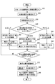
- FIG. 1 It is a block diagram which shows schematic structure of the HUD apparatus in 1st Embodiment. It is a schematic diagram which shows the display position of the virtual image in the HUD apparatus of FIG. It is an expanded sectional view which shows the stepping motor and reduction gear mechanism of FIG. It is an expansion perspective view which shows the stepping motor and reduction gear mechanism of FIG. It is a characteristic view for demonstrating the drive signal applied to the stepping motor of FIG. It is a schematic diagram for demonstrating the display position in the HUD apparatus of FIG. It is a top view which shows the stopper gear part of the reduction gear mechanism of FIG. It is a flowchart which the control part of FIG. 1 performs. It is a figure corresponding to FIG. 6 in 2nd Embodiment. It is a flowchart which the control part of 2nd Embodiment performs.
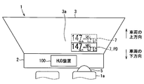
- the HUD device 100 As shown in FIG. 1, the HUD device 100 according to the first embodiment of the present disclosure is mounted on a vehicle 1 that is a kind of moving body and is housed in an instrument panel 2.
- the HUD device 100 projects an image on a windshield 3 as a projection member of the vehicle 1.
- the HUD device 100 displays a virtual image so that the occupant 5 of the vehicle 1 can visually recognize the image. That is, the display light of the image reflected by the windshield 3 reaches the eyes of the occupant 5 in the vehicle 1 and the occupant 5 perceives the display light as a virtual image 7.
- the occupant 5 can recognize various information from the virtual image 7. Examples of various information displayed as a virtual image as an image include vehicle state values such as a vehicle speed and a remaining amount of fuel, or navigation information such as road information and visibility assistance information.
- the surface on the indoor side is formed in a concave or flat shape that curves the projection surface 3 a on which the image is projected.
- a combiner separate from the vehicle 1 may be installed in the vehicle, and an image may be projected onto the combiner.
- the downward direction of the vehicle 1 indicates a direction in which gravity is generated when the vehicle 1 travels on a flat ground or stops on a flat ground. Further, the upward direction of the vehicle 1 indicates a direction opposite to the downward direction of the vehicle 1.
- the HUD device 100 includes a housing 10, a projection unit 20, a reflecting mirror 30, a stepping motor 40, a reduction gear mechanism 50, a command switch 60, and a control unit 70.
- the housing 10 is formed in a hollow shape that accommodates the other elements 20, 30, 40, 50, 70 of the HUD device 100, and is installed in the instrument panel 2 of the vehicle 1.
- the housing 10 has a dustproof sheet 12 that can transmit display light at a position facing the windshield 3 (see also FIG. 2) fixed in front of the driver's seat 1a on which the occupant 5 is seated in the vertical direction.
- Projection unit 20 is a liquid crystal projector.
- the projection unit 20 projects display light as an image by the screen 22 being transmitted and illuminated by a built-in backlight.
- the reflecting mirror 30 is formed by evaporating aluminum as the reflecting surface 32 on the surface of a base material made of synthetic resin or glass.
- the reflecting surface 32 is formed as a smooth curved surface as a concave surface having a recessed central portion.
- the reflecting mirror 30 reflects the display light from the projection unit 20 toward the windshield 3 through the dustproof sheet 12.
- the reflecting mirror 30 has a rotating shaft 34 that is rotatably supported by the housing 10.
- the display position PD which is the position of the virtual image display by the display light
- the rotation axis 34 sets the angle of the reflecting mirror 30 from the display position PD beyond the display range RD in which the image is visible from the occupant 5 to the out-of-display range ROD that is not visible from the occupant 5. It is possible.
- the stepping motor 40 is a permanent magnet type motor with a claw pole structure as shown in FIGS.
- the stepping motor 40 includes a casing 42, a rotor 44, and stators 46a and 46b.
- the hollow casing 42 is held by the housing 10 (see FIG. 1) and accommodates the other elements 44, 46a-b of the stepping motor 40.
- the rotor 44 is formed by assembling a magnet rotor 44a on the outer peripheral side of the motor shaft 40a.
- the motor shaft 40 a is rotatably supported by the casing 42.
- the motor shaft 40a rotates in the lower corresponding direction DD and the upper corresponding direction DU shown in FIG.
- the magnet rotor 44a is formed of permanent magnets each having a plurality of opposite magnetic poles.
- the two-phase stators 46 a and 46 b are held by the casing 42 on the outer peripheral side of the rotor 44.
- the A-phase stator 46a has magnetic yokes 47a and 47b and a coil 47c
- the B-phase stator 46b has magnetic yokes 48a and 48b and a coil 48c.
- the coil 47c disposed coaxially with the magnetic yokes 47a-b in the A phase and the coil 48c disposed coaxially with the magnetic yokes 48a-b in the B phase are offset from each other in the axial direction.
- the stepping motor 40 rotates the motor shaft 40a together with the magnet rotor 44a when the coils 47c and 48c of the phases A and B receive the excitation of the drive signal and are excited.
- the drive signal applied to the A-phase coil 47c follows a cosine function that alternates the voltage amplitude V in accordance with the electrical angle, as shown by a thick solid line in the graph of FIG.
- the drive signal applied to the B-phase coil 48c follows a sine function that alternates the voltage amplitude V according to the electrical angle, as shown by a thin solid line in the graph of FIG.
- the reduction gear mechanism 50 is formed by meshing a plurality of gears 52 to 59 in a casing 42.
- These gears 52 to 59 are made of a synthetic resin such as polybutylene terephthalate (PBT) resin.
- PBT polybutylene terephthalate
- the first stage gear 52 is formed on the motor shaft 40a.
- the first idler gear 53 and the first pinion gear 54 are supported by the casing 42 so as to be integrally rotatable.
- the first idler gear 53 meshes with the first stage gear 52 to reduce the rotation of the motor shaft 40 a and transmit it to the first pinion gear 54.
- the second idler gear 55 and the second pinion gear 56 are supported by the casing 42 so as to be integrally rotatable.
- the second idler gear 55 meshes with the first pinion gear 54 to further reduce the rotation of the gear 54 and transmit it to the second pinion gear 56.
- the third idler gear 57 and the third pinion gear 58 are supported by the casing 42 so as to be integrally rotatable.
- the third idler gear 57 is engaged with the second pinion gear 56 to further reduce the rotation of the gear 56 and transmit it to the third pinion gear 58.
- the final gear 59 is formed on the rotating shaft 34 and meshes with the third pinion gear 58 to further reduce the rotation of the gear 58 and transmit it to the reflecting mirror 30.
- the reduction gear mechanism 50 that forms such a rotation transmission path reduces the rotation of the lower corresponding direction DD output from the motor shaft 40 a to the reflection mirror 30 to reduce the angle of the reflection mirror 30.
- the corresponding display position PD is moved downward in the vehicle 1. That is, the lower corresponding direction DD is a direction in which an image displayed as a virtual image is moved downward in the vehicle 1.
- the reduction gear mechanism 50 transmits the rotation of the upper corresponding direction DU output from the motor shaft 40a toward the opposite side of the lower corresponding direction DD to the reflecting mirror 30 at a reduced speed, so that the angle of the reflecting mirror 30 is increased.
- the display position PD corresponding to is moved upward. That is, the upward corresponding direction DU is a direction in which an image displayed as a virtual image is moved upward.
- the predetermined angle due to the influence of the backlash is defined as the backlash equivalent angle ⁇ b.
- the first idler gear 53 of the gears 52 to 59 is provided with a partial gear-like stopper gear portion 53a.
- the stopper gear portion 53a is formed in a region of the first idler gear 53 that is less than 360 degrees in the rotational direction, and a plurality of teeth 53b are continuous only within the region.
- the command switch 60 is installed outside the housing 10, for example, on the steering handle of the vehicle 1, and can be operated by the occupant 5 on the driver's seat.
- the command switch 60 has two types of operation members 62 and 63 such as a push type. Specifically, the down operation member 62 receives a down control command for moving the display position PD downward according to the operation of the occupant 5. On the other hand, the up operation member 63 receives an up control command for moving the display position PD upward according to the operation of the occupant 5.
- the command switch 60 having such a configuration separately outputs a down control command signal input by the operation of the down operation member 62 and an up control command command signal input by the operation of the up operation member 63. .
- the control unit 70 is a control circuit as an electric circuit disposed inside the housing 10 as shown in FIG.
- the control unit 70 is mainly configured by a CPU 72 and has a memory unit 74.
- the CPU 72 can execute various processes by executing computer programs stored in the memory unit 74.
- the memory unit 74 stores a control step angle ⁇ c, a correction parameter A for correcting the control step angle ⁇ c, and the like.
- the control step angle ⁇ c of the present embodiment is stored in the nonvolatile memory of the memory unit 74
- the correction parameter A is stored in the volatile memory of the memory unit 74.
- the control unit 70 is electrically connected to the projection unit 20, the command switch 60, and the coils 47 c and 48 c of the stepping motor 40.
- the control unit 70 controls the projection of the display light from the projection unit 20 and controls the rotation of the stepping motor 40 in accordance with a control command from the occupant via the command switch 60. Specifically, when a command signal is input from the command switch 60, the control unit 70 calculates a control step angle ⁇ c for controlling the rotation of the stepping motor 40 based on the command signal. Then, the control unit 70 outputs a drive signal corresponding to the calculated control step angle ⁇ c to the coils 47c and 48c of the stepping motor 40.
- control step angle ⁇ c is a control angle with a predetermined electric angle between the electric stable points ⁇ s in the stepping motor 40 as a unit step angle.
- one step angle as a unit step angle corresponds to 180 degrees as an electrical angle, and when the motor shaft 40a is rotated by one step angle, the reduction gear mechanism 50 is not affected by backlash.
- the angle of the reflecting mirror 30 is changed by 0.176 degrees.
- the numbers 0 to 80 are assigned as the control step angle ⁇ c so that the numbers become larger as the control step angle ⁇ c increases in the upward corresponding direction DU.
- the control step angle ⁇ c functions as a control parameter associated with the display position PD and the angle of the reflecting mirror 30.
- control unit is also electrically connected to the engine switch 4 of the vehicle 1.
- the control unit 70 rotates the reflecting mirror 30 until the display position PD reaches the predetermined angle as the reset position PR in the reset direction DR toward the out-of-display range ROD. Yes.
- the reset direction DR is the lower corresponding direction DD.
- the reflecting mirror 30 is rotated in the initial setting direction DI from the outside display range ROD toward the initial position PI of the display range RD.
- the initial position PI is set to a position corresponding to the control step angle ⁇ c stored in the memory unit 74.
- the initial setting direction DI is the upward corresponding direction DU.
- step S10 the display position PD is moved from the reset position PR to the initial position PI.
- the motor shaft 40a is controlled so that the reflecting mirror 30 is rotated in the upward corresponding direction DU as the initial setting direction DI from the out-of-display range ROD toward the initial position PI.
- step S20 the setting of the initial position PI is completed. Specifically, when the angle of the reflecting mirror 30 reaches an angle corresponding to the initial position PI, that is, when the reflecting mirror 30 is rotated by the control step angle ⁇ c stored in the memory unit 74, the projection unit 20 projects the display light to display the image. The virtual image display is started. After the process of step S20, the process proceeds to step S30.
- step S30 as a display position adjustment mode, an input of a control command signal is received by the occupant 5 operating the command switch 60.
- the process proceeds to step S40.
- step S40 the current control command input in step S30 is determined. Specifically, whether the output direction of the rotation output to the stepping motor 40 according to the control command at the current determination timing is the same as the rotation direction output by the stepping motor 40 according to the control command at the previous determination timing It is determined whether the direction is reverse.
- the previous determination timing indicates the timing at which the determination is made in the previous step S40 in the present step S40 repeated in the loop of the flowchart.
- the output direction of the rotation output to the stepping motor 40 in accordance with the control command at the current determination timing instead of the comparison with the previous time Is the same direction as the initial setting direction DI or a reverse direction.
- step S50 If the determination in the same direction is made in this determination, the process proceeds to step S50.
- step S40 whether the output direction is the current upper corresponding direction DU with respect to the previous lower corresponding direction DD, or It is determined whether the current direction corresponds to the lower corresponding direction DD with respect to the previous corresponding direction DU.
- step S52 when it is determined that the output direction has changed from the upper corresponding direction DU to the lower corresponding direction DD, the process proceeds to step S52. If it is determined that the output direction is changed from the lower corresponding direction DD to the upper corresponding direction DU, the process proceeds to step S54.
- step S50 when the determination in the same direction is made in step S40, the reference step angle ⁇ 0 in the same direction is added to the control step angle ⁇ c. That is, the control step angle ⁇ c after the addition is obtained by adding the reference step angle ⁇ 0 in the same direction to the control step angle ⁇ c before the addition.
- step S60 After the process of step S50, the process proceeds to step S60.
- step S60 the correction parameter A is left as it is, and the process proceeds to step S70.
- step S52 the reverse step angle ⁇ 1 in the reverse direction. Is added to the control step angle ⁇ c. That is, the control step angle ⁇ c after the addition is obtained by adding the reverse step angle ⁇ 1 in the reverse direction to the control step angle ⁇ c before the addition.
- the reverse step angle ⁇ 1 is set to be equal to or larger than the sum of the reference step angle ⁇ 0 that is a step angle output to the stepping motor in response to the determination in the same direction in step S40 and the backlash equivalent angle ⁇ b. Is done.
- step S62 the process proceeds to step S62.
- step S62 the correction parameter A is rewritten based on the deviation estimated from the backlash equivalent angle ⁇ b with respect to the control step angle ⁇ c. Specifically, in the first embodiment, since the current output direction does not match the initial setting direction DI, the correction parameter A is rewritten to the backlash equivalent angle ⁇ b. After step S62, the process proceeds to step S70.
- step S54 If the determination in the reverse direction is made in step S40, and if it is determined that the output direction has changed from the lower corresponding direction DD to the upper corresponding direction DU, the reverse step angle ⁇ 1 in the reverse direction is determined in step S54. Is added to the control step angle ⁇ c. That is, as in step S52, the control step angle ⁇ c after the addition is obtained by adding the reverse step angle ⁇ 1 in the reverse direction to the control step angle ⁇ c before the addition. After step S54, the process proceeds to step S64.
- step S64 the correction parameter A is rewritten based on the deviation estimated from the backlash equivalent angle ⁇ b with respect to the control step angle ⁇ c. Specifically, in the first embodiment, the correction parameter A is rewritten to 0 because the current output direction matches the initial setting direction DI. After step S64, the process proceeds to step S70.
- step S70 after the processing of steps S60, S62, and S64, it is determined whether or not the operation for adjusting the display position PD is completed.
- the end may be determined as the set time elapses, or an end operation member that ends the display position adjustment mode is provided in the command switch 60 or the like, and it is determined whether or not an end control command is input by operating the end operation member. You may do it. If a negative determination is made in step S70, the process returns to step S30 again, and the processes in steps S30 to S70 are repeated. If an affirmation judging is made at Step S70, it will move to Step S72.
- step S72 the adjustment process of the display position PD is performed. Specifically, the reception of the control command signal is terminated when the occupant 5 operates the command switch 60. After the process of step S72, the process proceeds to step S80.
- step S80 the use of the HUD device 100 is terminated as the operation is terminated by turning off the engine switch 4. Specifically, while the projection of the display light by the projection unit 20 is stopped, the reflecting mirror 30 is rotated in the downward corresponding direction DD as the reset direction DR so that the display position PD moves to the reset position PR of the ROD outside the display range. Let As a result, the virtual image display of the image is reset. After the process of step S80, the process proceeds to step S90.
- step S90 after the display position PD moves to the reset position PR, the control step angle ⁇ c is updated with the correction parameter A. Specifically, the control step angle ⁇ c after the update is obtained by adding the value of the correction parameter A to the control step angle ⁇ c before the update. A series of processing is complete
- the backlash equivalent angle ⁇ b is one step angle.
- the reference step angle ⁇ 0 is set to one step angle
- the reverse step angle ⁇ 1 is set to a two step angle that is equal to or larger than the sum of the reference step angle ⁇ 0 and the backlash equivalent angle ⁇ b.
- the reverse step angle ⁇ 1 is set equal to the sum of the reference step angle ⁇ 0 and the backlash equivalent angle ⁇ b.
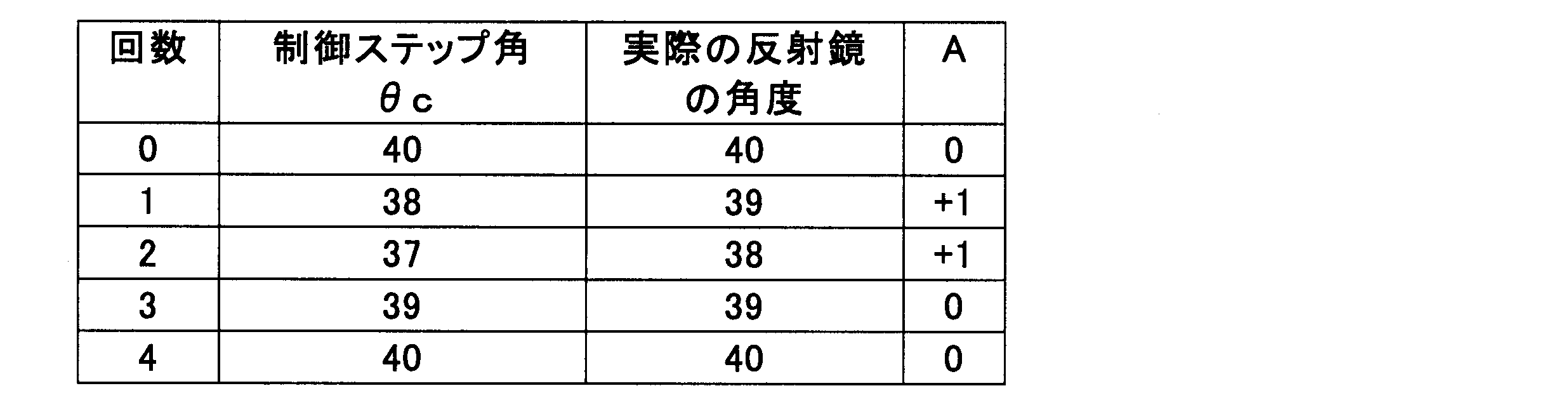
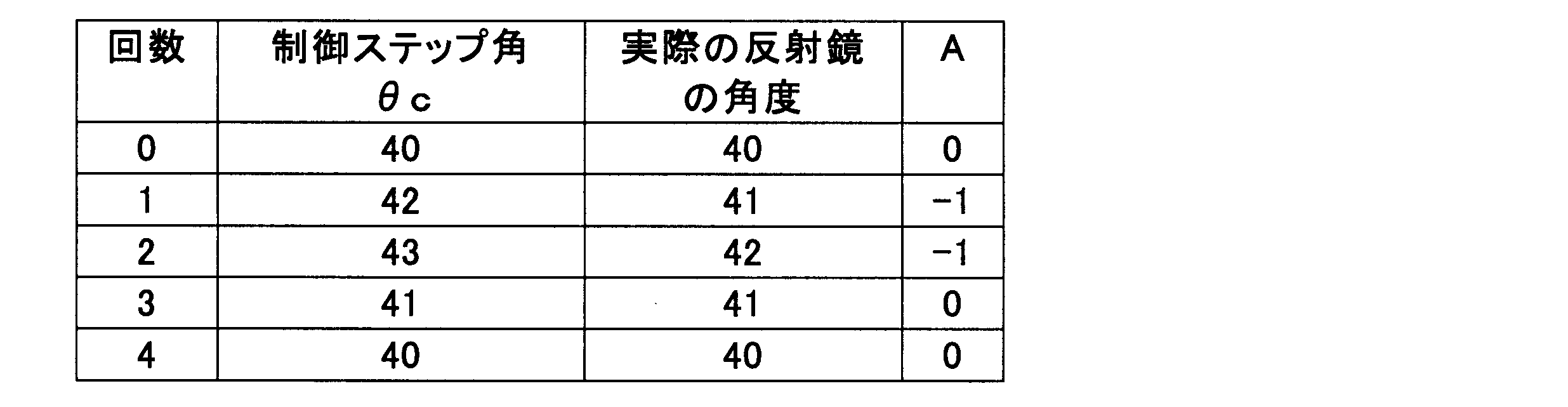
- control step angle ⁇ c the actual angle of the reflecting mirror 30, and the behavior of the correction parameter A are shown in Table 1.
- Table 1 in the loop of repeated steps S30 to S70, the control step angle ⁇ c, the actual angle of the reflecting mirror 30, and the correction parameter A at the time when step S70 is reached for each loop are stored in one line. Shown in correspondence. Further, in Table 1, the actual angle of the reflecting mirror 30 is shown in a step angle conversion in which an angle change of 0.176 degrees corresponding to the unit step angle of the control step angle ⁇ c is one step angle.
- steps S10 and S20 are executed. That is, the motor shaft 40a rotates in the upward corresponding direction, and the initial position PI is set.
- the control step angle ⁇ c is set to 40.
- the actual angle of the reflecting mirror 30 is 40, which is the same as the control step angle ⁇ c.
- the correction parameter A is set to 0 (see the 0th row).
- the reduction gear mechanism 50 at the time when the initial position PI is set is in a state where there is no hysteresis in the upper corresponding direction DU.
- step S30 an up control command is input in step S30. Then, the determination of the same direction is made in step S40, and the processes of steps S50 and S60 are executed.
- the control step angle ⁇ c is set to 41, which is 40, which is the control step angle ⁇ c before addition, and +1 which is the reference step angle ⁇ 0 in the same direction.
- the actual angle of the reflecting mirror 30 is 41, which is the same as the control step angle ⁇ c, because it is rotated in the same direction without the influence of backlash.
- the correction parameter A remains 0.
- step S40 it is determined that the reverse direction and the output direction has changed from the upper corresponding direction to the lower corresponding direction, and the processes of steps S52 and S62 are executed.
- the control step angle ⁇ c is set to 40, which is obtained by adding ⁇ 2 which is the reverse step angle ⁇ 1 in the reverse direction to 42 which is the control step angle ⁇ c before the addition.
- the actual angle of the reflecting mirror 30 is 41, which is different from the control step angle ⁇ c, because it does not rotate by the backlash equivalent angle ⁇ b due to the influence of the backlash.
- the correction parameter A is set to +1 corresponding to the backlash equivalent angle ⁇ b.
- step S30 a down control command is input in step S30. Then, the determination of the same direction is made in step S40, and the processes of steps S50 and S60 are executed.
- the control step angle ⁇ c is set to 39, which is 40, which is the control step angle ⁇ c before addition, and ⁇ 1 which is the reference step angle ⁇ 0 in the same direction.
- the actual angle of the reflecting mirror 30 is 40, which is different from the control step angle ⁇ c, with the deviation occurring at the third time, because it is rotated in the same direction without the influence of backlash.
- the correction parameter A remains +1.
- step S40 an up control signal is input in step S30.
- step S40 it is determined that the reverse direction and the output direction has changed from the lower corresponding direction DD to the upper corresponding direction DU, and the processes of steps S54 and S64 are executed.
- the control step angle ⁇ c is set to 41, which is 39 which is the control step angle ⁇ c before addition and +2 which is the reverse step angle ⁇ 1 in the reverse direction.
- the actual angle of the reflecting mirror 30 was not rotated by the backlash equivalent angle ⁇ b due to the influence of the backlash, so that the deviation that occurred up to the fourth time was canceled out, and was the same 41 as the control step angle ⁇ c.
- the correction parameter A is 0.
- step S70 the control step angle ⁇ c is 39, the actual angle of the reflecting mirror 30 is 40, and the correction parameter A is +1, but the control step angle ⁇ c is updated in S90. That is, the updated control step angle ⁇ c is updated to 40, which is 39 which is the control step angle ⁇ c before the update and the value +1 of the correction parameter A is added.
- the reverse step angle ⁇ 1 in the reverse direction which is the sum of the reference step angle ⁇ 0 and the backlash equivalent angle ⁇ b, becomes the control step angle ⁇ c. It was added. For this reason, it can be seen that the angle of the actual reflecting mirror 30 is certainly changed by one step angle with respect to one control command.
- control step angle ⁇ c is updated with the correction parameter A, the deviation from the actual position of the reflecting mirror 30 is eliminated. Thereby, when the engine switch 4 is turned on again, the control is started in a state where the control step angle ⁇ c and the actual angle of the reflecting mirror 30 coincide with each other.
- the backlash equivalent angle ⁇ b, the reference step angle ⁇ 0, and the reverse step angle ⁇ 1 have the same values as in the first embodiment.
- the control step angle ⁇ c, the actual angle of the reflecting mirror 30, and the behavior of the correction parameter A are shown in Table 2 as in the first embodiment.
- steps S10 and S20 are executed. That is, the motor shaft 40a rotates in the upward corresponding direction DU, and the initial position PI is set.
- the control step angle ⁇ c is set to 40.
- the actual angle of the reflecting mirror 30 is 40, which is the same as the control step angle ⁇ c.
- the correction parameter A is set to 0 (see the 0th row).
- the reduction gear mechanism 50 at the time when the initial position PI is set is in a state where there is no hysteresis in the upper corresponding direction DU.
- step S30 a down control command is input in step S30.
- step S40 it is determined that the reverse direction and the output direction has changed from the upper corresponding direction DU to the lower corresponding direction DD, and the processes of steps S52 and S62 are executed.
- the control step angle ⁇ c is set to 38, which is obtained by adding ⁇ 2 which is the reverse step angle ⁇ 1 in the reverse direction to 40 which is the control step angle ⁇ c before the addition.
- the actual angle of the reflecting mirror 30 is 39 different from the control step angle ⁇ c because it does not rotate by the backlash equivalent angle ⁇ b due to the influence of the backlash.
- the correction parameter A is set to +1 corresponding to the backlash equivalent angle ⁇ b.
- step S30 a down control command is input in step S30.
- step S40 the determination of the same direction is made in step S40, and the processes of steps S50 and S60 are executed.
- the control step angle ⁇ c is set to 37 which is obtained by adding ⁇ 1 which is the reference step angle ⁇ 0 in the same direction to 38 which is the control step angle ⁇ c before addition. Since the actual angle of the reflecting mirror 30 is rotated in the same direction without the influence of backlash, it is 38 different from the control step angle ⁇ c, with the deviation occurring at the first time.
- the correction parameter A remains +1.
- step S40 an up control command is input in step S30.
- step S40 it is determined that the reverse direction and the output direction has changed from the lower corresponding direction DD to the upper corresponding direction DU, and the processes of steps S54 and S64 are executed.
- the control step angle ⁇ c is set to 39, which is obtained by adding +2 which is the reverse step angle ⁇ 1 in the reverse direction to 37 which is the control step angle ⁇ c before addition.
- the actual angle of the reflecting mirror 30 was not rotated by the backlash equivalent angle ⁇ b due to the influence of the backlash, so the deviation that occurred until the second time was canceled out, and was 39, which is the same as the control step angle ⁇ c.
- the correction parameter A is 0.
- step S70 the control step angle ⁇ c is 40, and the actual position of the reflecting mirror 30 is 40. Since the correction parameter A is 0, the control step angle ⁇ c is not substantially updated.
- the reverse step angle ⁇ 1 in the reverse direction which is the sum of the reference step angle ⁇ 0 and the backlash equivalent angle ⁇ b, is set as the control step angle ⁇ c. It has been added. For this reason, it can be seen that the angle of the actual reflecting mirror 30 is certainly changed by one step angle with respect to one control command.
- control unit 70 that executes step S40 constitutes a “determination unit”
- control unit 70 that executes steps S52 and S54 constitutes a “reverse addition unit”
- executes step S50 The control unit 70 that configures the “same direction addition unit”, the control unit 70 that executes step S90 configures the “update unit”, and the control unit 70 that executes steps S60, S62, and S64 defines the “rewrite unit”.
- the control unit 70 configured and executing step S80 constitutes a “reset unit”, and the control unit 70 executing steps S10 and S20 constitutes an “initial position setting unit”.
- the control unit 70 that calculates the control step angle ⁇ c that controls the rotation of the stepping motor 40
- the reverse step angle ⁇ 1 in the reverse direction is added to the control step angle ⁇ c so as to be equal to or greater than the sum with the backlash equivalent angle ⁇ b of the gear mechanism 50.
- the stepping motor 40 rotates in the reverse direction of the previous step by the reverse step angle ⁇ 1.
- the rotation amount of the reflecting mirror 30 can be ensured, and the position PD of the virtual image display can be reliably moved. Therefore, the occupant 5 who visually recognizes the virtual image 7 can move the position PD of the virtual image display as desired, so that a sense of incongruity is reduced.
- the reference step angle ⁇ 0 in the same direction is added to the control step angle ⁇ c.
- the stepping motor 40 rotates in the same direction as the previous time by the reference step angle ⁇ 0.
- the rotation amount of the reflecting mirror 30 can be ensured, and the position PD of the virtual image display can be reliably moved. Therefore, since the occupant 5 who visually recognizes the virtual image 7 can move the virtual image display position PD as desired even in the same direction as the previous time, a sense of incongruity is reduced.
- the memory unit 74 that stores the control step angle ⁇ c and the correction parameter A is provided, and the control unit 70 performs the control step angle ⁇ c with respect to the control step angle ⁇ c when the determination in the opposite direction is performed.
- the correction parameter A is rewritten based on the deviation estimated from the backlash equivalent angle ⁇ b.
- the control step angle ⁇ c is corrected by the correction parameter A. Since the control step angle ⁇ c is corrected by the correction parameter A reflecting the deviation estimated from the backlash equivalent angle ⁇ b with respect to the control step angle ⁇ c, the actual angle of the reflector 30 due to the influence of the backlash and the control step angle ⁇ c It is possible to suppress the deviation from accumulating the use of the HUD device 100 repeatedly. Therefore, it is possible to reduce a sense of incongruity due to a deviation between the display position for control and the actual display position PD.
- the correction parameter A when the determination in the same direction as the previous time is made, the correction parameter A is left as it is. In the case of the same direction, there is no influence of backlash, so that the uncomfortable feeling can be reduced by leaving the correction parameter A as it is.
- the control unit 70 resets the image display by rotating the reflecting mirror 30 in the reset direction DR toward the ROD outside the image display range. Then, the control unit 70 starts the image display by rotating the reflecting mirror 30 in the initial setting direction DI from the out-of-display range ROD toward the initial position PI corresponding to the control step angle ⁇ c.
- the correction parameter A is 0.
- the parameter A is the backlash equivalent angle ⁇ b.
- the control unit 70 makes the determination in the same direction as the previous time. In this case, the correction parameter A is left as it is.
- the control unit 70 sets the correction parameter A to the backlash equivalent angle ⁇ b when the determination in the direction opposite to the previous time is made and the output direction is the lower corresponding direction DD.
- the correction parameter A is set to 0.
- the second embodiment of the present disclosure is a modification of the first embodiment.
- the second embodiment will be described with a focus on differences from the first embodiment.
- the reset direction DR is the upper corresponding direction DU
- the initial setting direction DI is the lower corresponding direction DD.
- step S210 the display position PD is moved from the reset position PR to the initial position PI.
- the motor shaft 40a is controlled so that the reflecting mirror 30 is rotated in the downward corresponding direction DD as the initial setting direction DI from the out-of-display range ROD toward the initial position PI.
- the processing in steps S220 to S240 is the same as the processing in steps S20 to S40 in the first embodiment.
- step S240 The processing in steps S250 and S260 when the determination in the same direction is made in step S240 is the same as the processing in steps S50 and S60 in the first embodiment. After the process of step S260, the process proceeds to step S270.
- step S252 when it is determined that the reverse direction is determined in step S240 and the output direction is changed from the upper corresponding direction DU to the lower corresponding direction DD is the process of step S252 of the first embodiment. This is the same as the processing in step S52. After the process of step S252, the process proceeds to step S262.
- step S262 the correction parameter A is rewritten based on the deviation estimated from the backlash equivalent angle ⁇ b with respect to the control step angle ⁇ c. Specifically, in the second embodiment, since the current output direction coincides with the initial setting direction DI, the correction parameter A is rewritten to 0. After the process of step S262, the process proceeds to step S270.
- step S254 the processing in step S254 is step S54 of the first embodiment. This is the same as the process. After the process of step S254, the process proceeds to step S264.
- step S264 the correction parameter A is rewritten based on the deviation estimated from the backlash equivalent angle ⁇ b with respect to the control step angle ⁇ c. Specifically, in the second embodiment, since the current output direction does not coincide with the initial setting direction DI, the correction parameter A is rewritten to the backlash equivalent angle ⁇ b. After the process of step S264, the process proceeds to step S270.
- steps S270 to S272 after the processes in steps S260, S262, and S264 are the same as the processes in steps S70 to S72 in the first embodiment. After the process of step S272, the process proceeds to step S280.
- step S280 the operation of the HUD device 200 is terminated when the operation is terminated by turning off the engine switch 4. Specifically, the projection of the display light by the projection unit 20 is stopped, and the reflecting mirror 30 in the upward corresponding direction DU as the reset direction DR so that the display position PD moves to the reset position PR of the ROD outside the display range of the image. Rotate. As a result, the virtual image display of the image is reset.
- step S290 A series of processing is completed by step S290 similar to step S90 of the first embodiment.
- Example 3 the backlash equivalent angle ⁇ b is one step angle.
- the reference step angle ⁇ 0 is set to one step angle
- the reverse step angle ⁇ 1 is set to a two step angle that is equal to or larger than the sum of the reference step angle ⁇ 0 and the backlash equivalent angle ⁇ b.
- the reverse step angle ⁇ 1 is set equal to the sum of the reference step angle ⁇ 0 and the backlash equivalent angle ⁇ b.
- the control step angle ⁇ c, the actual angle of the reflecting mirror 30, and the behavior of the correction parameter A are shown in Table 3 as in the first embodiment.
- steps S210 and S220 are executed. That is, the motor shaft 40a rotates in the lower corresponding direction DD, and the initial position PI is set.
- the control step angle ⁇ c is set to 40.
- the actual angle of the reflecting mirror 30 is 40, which is the same as the control step angle ⁇ c.
- the correction parameter A is set to 0 (see the 0th row).
- the reduction gear mechanism 50 at the time when the initial position PI is set is in a state where there is no hysteresis in the lower corresponding direction DD.
- step S230 a down control command is input in step S230. Then, the determination in the same direction is made in step S240, and the processes in steps S250 and S260 are executed.
- the control step angle ⁇ c is set to 39, which is 40, which is the control step angle ⁇ c before addition, and ⁇ 1 which is the reference step angle ⁇ 0 in the same direction.
- the actual angle of the reflecting mirror 30 is 39, which is the same as the control step angle ⁇ c, because it is rotated in the same direction without the influence of backlash.
- the correction parameter A remains 0.
- step S230 an up control command is input in step S230.
- step S240 it is determined that the reverse direction and the output direction has changed from the lower corresponding direction DD to the upper corresponding direction DU, and the processes of steps S254 and S264 are executed.
- the control step angle ⁇ c is set to 40, which is obtained by adding +2 which is the reverse step angle ⁇ 1 in the reverse direction to 38 which is the control step angle ⁇ c before addition.
- the actual angle of the reflecting mirror 30 is 39 different from the control step angle ⁇ c because it does not rotate by the backlash equivalent angle ⁇ b due to the influence of the backlash.
- the correction parameter A is set to ⁇ 1 which is the backlash equivalent angle ⁇ b.
- step S230 In the fourth time, an up control command is input in step S230. Then, the determination in the same direction is made in step S240, and the processes in steps S250 and S260 are executed.
- the control step angle ⁇ c is set to 41, which is 40, which is the control step angle ⁇ c before addition, and +1 which is the reference step angle ⁇ 0 in the same direction.
- the actual angle of the reflecting mirror 30 is 40, which is different from the control step angle ⁇ c, with the deviation occurring at the third time, because it is rotated in the same direction without the influence of backlash.
- the correction parameter A remains -1.
- step S230 a down control command is input in step S230.
- step S240 it is determined that the reverse direction and the output direction has changed from the upper corresponding direction DU to the lower corresponding direction DD, and the processes of steps S252 and S262 are executed.
- the control step angle ⁇ c is set to 39, which is 41, which is the control step angle ⁇ c before addition, and ⁇ 2 which is the reverse step angle ⁇ 1 in the reverse direction.
- the actual angle of the reflecting mirror 30 was not rotated by the backlash equivalent angle ⁇ b due to the effect of backlash, so the deviation that occurred up to the fourth time was canceled out, and was 39, which is the same as the control step angle ⁇ c.
- the correction parameter A is 0.
- step S270 the control step angle ⁇ c is 39, and the actual position of the reflecting mirror 30 is 39. Since the correction parameter A is 0, the control step angle ⁇ c is not substantially updated.
- the reverse step angle ⁇ 1 in the reverse direction which is the sum of the reference step angle ⁇ 0 and the backlash equivalent angle ⁇ b, becomes the control step angle ⁇ c. It has been added. For this reason, it can be seen that the angle of the actual reflecting mirror 30 is certainly changed by one step angle with respect to one control command.
- the backlash equivalent angle ⁇ b, the reference step angle ⁇ 0, and the reverse step angle ⁇ 1 are the same values as in the third embodiment.
- the control step angle ⁇ c, the actual angle of the reflecting mirror 30, and the behavior of the correction parameter A are shown in Table 4 as in the first embodiment.
- steps S210 and S220 are executed. That is, the motor shaft 40a rotates in the lower corresponding direction DD, and the initial position PI is set.
- the control step angle ⁇ c is set to 40.
- the actual angle of the reflecting mirror 30 is 40, which is the same as the control step angle ⁇ c.
- the correction parameter A is set to 0 (see the 0th row).
- the reduction gear mechanism 50 at the time when the initial position PI is set is in a state where there is no hysteresis in the lower corresponding direction DD.
- step S230 an up control command is input in step S230.
- step S240 it is determined that the reverse direction and the output direction has changed from the lower corresponding direction to the upper corresponding direction, and the processes of steps S254 and S264 are executed.
- the control step angle ⁇ c is set to 42, which is 40 which is the control step angle ⁇ c before addition and +2 which is the reverse step angle ⁇ 1 in the reverse direction.
- the actual angle of the reflecting mirror 30 is 41, which is different from the control step angle ⁇ c, because it does not rotate by the backlash equivalent angle due to the influence of the backlash.
- the correction parameter A is set to ⁇ 1 which is the backlash equivalent angle ⁇ b.
- step S230 In the second time, an up control command is input in step S230. Then, the determination in the same direction is made in step S240, and the processes in steps S250 and S260 are executed.
- the control step angle ⁇ c is set to 43, which is obtained by adding +1 which is the reference step angle ⁇ 0 in the same direction to 42 which is the control step angle ⁇ c before addition. Since the actual angle of the reflecting mirror 30 is rotated in the same direction without the influence of backlash, it is 42 different from the control step angle ⁇ c with the deviation generated in the first time.
- the correction parameter A remains -1.
- step S230 a down control command is input in step S230.
- step S240 it is determined that the reverse direction and the output direction has changed from the upper corresponding direction DU to the lower corresponding direction DD, and the processes of steps S252 and S262 are executed.
- the control step angle ⁇ c is set to 41, which is 43, which is the control step angle ⁇ c before addition, and ⁇ 2 which is the reverse step angle ⁇ 1 in the reverse direction.
- the actual angle of the reflecting mirror 30 was not rotated by the backlash equivalent angle ⁇ b due to the influence of the backlash, so that the deviation that occurred until the second time was canceled out, and was the same 41 as the control step angle ⁇ c.
- the correction parameter A is 0.
- step S270 the control step angle is 40, and the actual position of the reflecting mirror 30 is 40. Since the correction parameter A is 0, the control step angle ⁇ c is not substantially updated.
- the reverse step angle ⁇ 1 in the reverse direction which is the sum of the reference step angle ⁇ 0 and the backlash equivalent angle ⁇ b, becomes the control step angle ⁇ c. It has been added. For this reason, it can be seen that the angle of the actual reflecting mirror 30 is certainly changed by one step angle with respect to one control command.
- control unit 70 is equal to or greater than the sum of the reference step angle ⁇ 0 and the backlash equivalent angle ⁇ b of the reduction gear mechanism 50 when the determination in the reverse direction is made in step S240.
- the reverse step angle ⁇ 1 in the reverse direction is added to the control step angle ⁇ c. Therefore, it is possible to achieve the operational effects according to the first embodiment.
- the control unit 70 determines the same direction as the previous time. In this case, the correction parameter A is left as it is. Further, the control unit 70 sets the correction parameter A to the backlash equivalent angle ⁇ b when the determination in the direction opposite to the previous time is made and the output direction is the upward corresponding direction DU, When the determination of the reverse direction is made and the output direction is the downward corresponding direction DD, the correction parameter A is set to 0. By setting the correction parameter A in this way, the deviation between the actual angle of the reflecting mirror 30 and the control step angle ⁇ c is accumulated with repeated use corresponding to the reset direction DR and the initial setting direction DI. This is surely suppressed.
- control unit 70 that executes step S240 constitutes a “determination unit”
- control unit 70 that executes steps S252 and S254 constitutes a “reverse addition unit”, and executes step S250.
- the control unit 70 configured and executing step S280 constitutes a “reset unit”, and the control unit 70 executing steps S210 and S220 constitutes an “initial position setting unit”.
- the order of processing based on the flowcharts of FIGS. 8 and 10 may be switched within an appropriate range.
- the order of processing can be changed in steps S50 and S60, S52 and S62, or S54 and S64.
- the correction parameter A in step S90 can be updated before step S72 or S80.
- the reverse step angle ⁇ 1 may be larger than the sum of the reference step angle ⁇ 0 and the backlash equivalent angle ⁇ b.
- the reference step angle ⁇ 0 is 1 step angle and the backlash equivalent angle ⁇ b is 1.4 steps
- the stepping motor 40 is rounded up so as to correspond to the electric stable point ⁇ s, and the reverse step angle ⁇ 1 is set to 3 It can be a step.
- the reference step angle ⁇ 0 may be an angle other than one step angle corresponding to an electrical angle of 180 degrees.
- control unit 70 may not update the control step angle ⁇ c with the correction parameter A.
- control unit 70 may not rewrite the correction parameter A based on the deviation estimated from the backlash equivalent angle ⁇ b with respect to the control step angle ⁇ c when the determination in the reverse direction is made.
- the memory unit 74 may not store the correction parameter A.
- control unit 70 may not reset the image display by rotating the reflecting mirror 30 in the reset direction DR toward the ROD outside the image display range.
- a temperature sensor that measures the use environment temperature may be provided, and the control unit 70 may vary the reverse step angle ⁇ 1 based on the temperature measured by the temperature sensor.
- the control unit 70 changes the reverse step with respect to the measured temperature using, for example, 60 ° C. and 10 ° C. as boundary values. According to this, even if each gear 52 to 59 expands or contracts due to temperature and the backlash equivalent angle ⁇ b changes, it is possible to cope with this.
- control unit 70 may be disposed outside the housing 10.
- a method other than the command switch 60 can be used to input a control command to the control unit 70.
- a touch input to an image-displayed switch such as a car navigation device or an input by recognizing a gesture or the like can be employed.
- the present disclosure may be applied to various moving bodies (transport equipment) such as ships or airplanes other than the vehicle 1.
Landscapes
- Engineering & Computer Science (AREA)
- Chemical & Material Sciences (AREA)
- Combustion & Propulsion (AREA)
- Transportation (AREA)
- Mechanical Engineering (AREA)
- Physics & Mathematics (AREA)
- General Physics & Mathematics (AREA)
- Optics & Photonics (AREA)
- Power Engineering (AREA)
- Instrument Panels (AREA)
Abstract
Description
表示光を投射する投射部と、
投射部からの表示光を投影部材に向けて反射する反射鏡と、
回転を出力するステッピングモータと、
複数のギアからなり、ステッピングモータから出力されて反射鏡へ伝達される回転を、減速する減速ギア機構と、
乗員からの制御指令に従って、ステッピングモータの回転を制御する制御ステップ角を演算する制御部とを備え、
制御部は、
今回の判定タイミングにおける制御指令に従ってステッピングモータに出力させる回転の出力方向が、前回の判定タイミングにおける制御指令に従ってステッピングモータにより出力された回転の方向と、同方向であるか逆方向であるかを判定する判定部と、
判定部において同方向の判定が下されるのに応じてステッピングモータを回転させるステップ角を基準ステップ角として、判定部において逆方向の判定が下された場合に、基準ステップ角と減速ギア機構のバックラッシ相当角との和以上となる、逆方向の逆ステップ角を制御ステップ角に加算する逆方向加算部とを有する。
図1に示すように、本開示の第1実施形態によるHUD装置100は、移動体の一種である車両1に搭載され、インストルメントパネル2内に収容されている。HUD装置100は、車両1の投影部材としてのウインドシールド3に画像を投影する。これによりHUD装置100は、画像を車両1の乗員5により視認可能に虚像表示する。すなわち、ウインドシールド3に反射される画像の表示光が、車両1の室内において乗員5の眼に到達し、当該乗員5が当該表示光を虚像7として知覚する。そして、乗員5は、虚像7により各種情報を認識することができる。画像として虚像表示される各種情報としては、例えば、車速、燃料残量等の車両状態値、又は道路情報、視界補助情報等のナビゲーション情報が挙げられる。
実施例1では、バックラッシ相当角θbが1ステップ角分である。そして、基準ステップ角θ0が1ステップ角に設定され、逆ステップ角θ1が基準ステップ角θ0とバックラッシ相当角θbの和以上となる2ステップ角に設定されている。特に実施例1では、逆ステップ角θ1が基準ステップ角θ0とバックラッシ相当角θbの和と等しく設定されている。

実施例2でも、バックラッシ相当角θb、基準ステップ角θ0、逆ステップ角θ1が実施例1と同じ値となっている。ここで、制御ステップ角θc、実際の反射鏡30の角度、及び補正パラメータAの挙動を実施例1と同様に表2に示す。
以上説明した第1実施形態の作用効果を以下に説明する。
本開示の第2実施形態は第1実施形態の変形例である。第2実施形態について、第1実施形態とは異なる点を中心に説明する。
実施例3では、バックラッシ相当角θbが1ステップ角分である。そして、基準ステップ角θ0が1ステップ角に設定され、逆ステップ角θ1が基準ステップ角θ0とバックラッシ相当角θbの和以上となる2ステップ角に設定されている。特に実施例3では、逆ステップ角θ1が基準ステップ角θ0とバックラッシ相当角θbの和と等しく設定されている。ここで、制御ステップ角θc、実際の反射鏡30の角度、及び補正パラメータAの挙動を実施例1と同様に表3に示す。
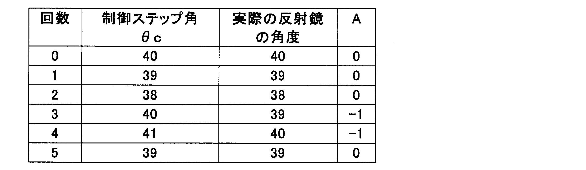
実施例4でも、バックラッシ相当角θb、基準ステップ角θ0、逆ステップ角θ1が実施例3と同じ値となっている。ここで、制御ステップ角θc、実際の反射鏡30の角度、及び補正パラメータAの挙動を実施例1と同様に表4に示す。
以上、本開示の複数の実施形態について説明したが、本開示は、それらの実施形態に限定して解釈されるものではなく、本開示の要旨を逸脱しない範囲内において種々の実施形態及び組み合わせに適用することができる。
Claims (7)
- 移動体(1)に搭載され、投影部材(3)に画像を投影することにより、前記画像を乗員(5)により視認可能に虚像表示するヘッドアップディスプレイ装置であって、
表示光を投射する投射部(20)と、
前記投射部からの表示光を前記投影部材に向けて反射する反射鏡(30)と、
回転を出力するステッピングモータ(40)と、
複数のギア(52~59)からなり、前記ステッピングモータから出力されて前記反射鏡へ伝達される回転を、減速する減速ギア機構(50)と、
前記乗員からの制御指令に従って、前記ステッピングモータの回転を制御する制御ステップ角(θc)を演算する制御部(70)とを備え、
前記制御部は、
今回の判定タイミングにおける前記制御指令に従って前記ステッピングモータに出力させる回転の出力方向が、前回の判定タイミングにおける前記制御指令に従って前記ステッピングモータにより出力された回転の方向と、同方向であるか逆方向であるかを判定する判定部(S40,S240)と、
前記判定部において前記同方向の判定が下されるのに応じて前記ステッピングモータを回転させるステップ角を基準ステップ角(θ0)として、前記判定部において前記逆方向の判定が下された場合に、前記基準ステップ角と前記減速ギア機構のバックラッシ相当角(θb)との和以上となる、前記逆方向の逆ステップ角(θ1)を前記制御ステップ角に加算する逆方向加算部(S52,S54,S252,S254)とを有するヘッドアップディスプレイ装置。 - 前記制御部は、前記判定部において前記同方向の判定が下された場合に、前記同方向の前記基準ステップ角を前記制御ステップ角に加算する同方向加算部(S50,S250)を有する請求項1に記載のヘッドアップディスプレイ装置。
- 前記制御ステップ角、及び前記制御ステップ角を補正するための補正パラメータ(A)を記憶するメモリ部(74)を更に備え、
前記制御部は、
前記補正パラメータにより前記制御ステップ角を更新する更新部(S90,S290)と、
前記判定部において前記逆方向の判定が下された場合に、前記制御ステップ角に対する前記バックラッシ相当角から推定されるずれに基づいて前記補正パラメータを書き換える書換部(S60,S62,S64,S260,S262,S264)とを有する請求項1又は2に記載のヘッドアップディスプレイ装置。 - 前記書換部は、前記判定部において前記同方向の判定が下された場合に、前記補正パラメータをそのままとする請求項3に記載のヘッドアップディスプレイ装置。
- 前記制御部は、
前記画像の表示範囲外(ROD)に向かうリセット方向(DR)に前記反射鏡を回転させて、前記画像の表示をリセットするリセット部(S80,S280)と、
前記表示範囲外から初期位置(PI)に向かう初期設定方向(DI)に前記反射鏡を回転させて、前記画像の表示を始める初期位置設定部(S10,S20,S210,S220)とを有し、
前記書換部は、
前記判定部において前記同方向の判定が下された場合に、前記補正パラメータをそのままとし、
前記判定部において前記逆方向の判定が下された場合であって、前記出力方向が前記初期設定方向と一致する場合では、前記補正パラメータを0とし、
前記判定部において前記逆方向の判定が下された場合であって、前記出力方向が前記初期設定方向と一致しない場合では、前記補正パラメータを前記バックラッシ相当角分とする請求項3又は4に記載のヘッドアップディスプレイ装置。 - 前記リセット方向は、前記画像を前記移動体の下方向へ移動させる下対応方向(DD)であり、
前記初期設定方向は、前記画像を前記移動体の上方向へ移動させる上対応方向(DU)であり、
前記書換部(S60,S62,S64)は、
前記判定部において前記同方向の判定が下された場合に、前記補正パラメータをそのままとし、
前記判定部において前記逆方向の判定が下された場合であって、前記出力方向が前記下対応方向である場合に、前記補正パラメータを前記バックラッシ相当角分とし、
前記判定部において前記逆方向の判定が下された場合であって、前記出力方向が前記上対応方向である場合に、前記補正パラメータを0とする請求項5に記載のヘッドアップディスプレイ装置。 - 前記リセット方向は、前記画像を前記移動体の上方向へ移動させる上対応方向であり、
前記初期設定方向は、前記画像を前記移動体の下方向へ移動させる下対応方向であり、
前記書換部(S260,S262,S264)は、
前記判定部において前記同方向の判定が下された場合に、前記補正パラメータをそのままとし、
前記判定部において前記逆方向の判定が下された場合であって、前記出力方向が前記上対応方向である場合に、前記補正パラメータを前記バックラッシ相当角分とし、
前記判定部において前記逆方向の判定が下された場合であって、前記出力方向が前記下対応方向である場合に、前記補正パラメータを0とする請求項5に記載のヘッドアップディスプレイ装置。
Priority Applications (5)
| Application Number | Priority Date | Filing Date | Title |
|---|---|---|---|
| US15/548,907 US10139622B2 (en) | 2015-02-19 | 2016-02-05 | Head-up display device |
| SE1750962A SE541056C2 (en) | 2015-02-19 | 2016-02-05 | Head-up display device |
| CN201680010368.3A CN107250892B (zh) | 2015-02-19 | 2016-02-05 | 平视显示装置 |
| KR1020177022751A KR101930188B1 (ko) | 2015-02-19 | 2016-02-05 | 헤드업 디스플레이 장치 |
| DE112016000830.9T DE112016000830T5 (de) | 2015-02-19 | 2016-02-05 | Head-Up Anzeigevorrichtung |
Applications Claiming Priority (2)
| Application Number | Priority Date | Filing Date | Title |
|---|---|---|---|
| JP2015-030667 | 2015-02-19 | ||
| JP2015030667A JP6406050B2 (ja) | 2015-02-19 | 2015-02-19 | ヘッドアップディスプレイ装置 |
Publications (1)
| Publication Number | Publication Date |
|---|---|
| WO2016132701A1 true WO2016132701A1 (ja) | 2016-08-25 |
Family
ID=56688954
Family Applications (1)
| Application Number | Title | Priority Date | Filing Date |
|---|---|---|---|
| PCT/JP2016/000605 Ceased WO2016132701A1 (ja) | 2015-02-19 | 2016-02-05 | ヘッドアップディスプレイ装置 |
Country Status (7)
| Country | Link |
|---|---|
| US (1) | US10139622B2 (ja) |
| JP (1) | JP6406050B2 (ja) |
| KR (1) | KR101930188B1 (ja) |
| CN (1) | CN107250892B (ja) |
| DE (1) | DE112016000830T5 (ja) |
| SE (1) | SE541056C2 (ja) |
| WO (1) | WO2016132701A1 (ja) |
Cited By (1)
| Publication number | Priority date | Publication date | Assignee | Title |
|---|---|---|---|---|
| WO2023112917A1 (ja) * | 2021-12-14 | 2023-06-22 | 矢崎総業株式会社 | ヘッドアップディスプレイ装置 |
Families Citing this family (5)
| Publication number | Priority date | Publication date | Assignee | Title |
|---|---|---|---|---|
| JP6822014B2 (ja) * | 2016-08-31 | 2021-01-27 | 日本精機株式会社 | 虚像表示装置 |
| KR102004504B1 (ko) * | 2018-08-28 | 2019-07-26 | 에스케이텔레콤 주식회사 | 전방 상향 시현용 광학시스템 |
| US12339447B2 (en) * | 2020-11-13 | 2025-06-24 | Panasonic Automotive Systems Company Of America, Division Of Panasonic Corporation Of North America | Temperature variable HUD motor control |
| CN112848425A (zh) * | 2020-12-31 | 2021-05-28 | 宁波锦辉光学科技有限公司 | 一种应用于hud的自由反射镜的制造工艺 |
| JP7681501B2 (ja) * | 2021-12-20 | 2025-05-22 | マクセル株式会社 | ヘッドアップディスプレイ装置 |
Citations (5)
| Publication number | Priority date | Publication date | Assignee | Title |
|---|---|---|---|---|
| WO2008001642A1 (fr) * | 2006-06-29 | 2008-01-03 | Nippon Seiki Co., Ltd. | Instrument de mesure à aiguille |
| JP2010284015A (ja) * | 2009-06-05 | 2010-12-16 | Mycom Inc | ステッピングモータ駆動装置及びコントローラ |
| JP2011207430A (ja) * | 2010-03-30 | 2011-10-20 | Denso Corp | ヘッドアップディスプレイ装置 |
| JP2012023806A (ja) * | 2010-07-12 | 2012-02-02 | Denso Corp | 車両用ヘッドアップディスプレイ装置 |
| JP2013190472A (ja) * | 2012-03-12 | 2013-09-26 | Denso Corp | 車両用ヘッドアップディスプレイ装置 |
Family Cites Families (13)
| Publication number | Priority date | Publication date | Assignee | Title |
|---|---|---|---|---|
| JP4949487B2 (ja) * | 2010-01-13 | 2012-06-06 | 本田技研工業株式会社 | 車両用表示装置 |
| JP5071508B2 (ja) * | 2010-03-30 | 2012-11-14 | 株式会社デンソー | 車両用ヘッドアップディスプレイ装置 |
| JP2012179935A (ja) * | 2011-02-28 | 2012-09-20 | Jvc Kenwood Corp | 車両用表示装置 |
| JP5464219B2 (ja) * | 2012-02-03 | 2014-04-09 | 株式会社デンソー | 車両用ヘッドアップディスプレイ装置 |
| JP5464222B2 (ja) * | 2012-02-08 | 2014-04-09 | 株式会社デンソー | 車両用ヘッドアップディスプレイ装置 |
| JP5799920B2 (ja) * | 2012-09-07 | 2015-10-28 | 株式会社デンソー | 車両用ヘッドアップディスプレイ装置 |
| JP2014058999A (ja) * | 2012-09-14 | 2014-04-03 | Denso Corp | ステップモータ |
| FR2996927B1 (fr) * | 2012-10-12 | 2014-12-26 | Airbus Operations Sas | Poste de pilotage avec dispositif de visualisation tete haute, notamment pour un aeronef |
| JP6265601B2 (ja) | 2013-01-24 | 2018-01-24 | 矢崎総業株式会社 | ヘッドアップディスプレイ装置 |
| TWI493226B (zh) * | 2013-04-19 | 2015-07-21 | Delta Electronics Inc | 抬頭投影系統 |
| JP6111940B2 (ja) * | 2013-09-05 | 2017-04-12 | 株式会社デンソー | 車両用ヘッドアップディスプレイ装置 |
| KR101558658B1 (ko) * | 2013-09-06 | 2015-10-07 | 현대자동차주식회사 | 차량용 헤드업 디스플레이 장치 |
| CN103487941A (zh) * | 2013-09-23 | 2014-01-01 | 苏州佳视特信息科技有限公司 | 一种汽车信息显示方法及装置 |
-
2015
- 2015-02-19 JP JP2015030667A patent/JP6406050B2/ja active Active
-
2016
- 2016-02-05 WO PCT/JP2016/000605 patent/WO2016132701A1/ja not_active Ceased
- 2016-02-05 SE SE1750962A patent/SE541056C2/en not_active IP Right Cessation
- 2016-02-05 DE DE112016000830.9T patent/DE112016000830T5/de not_active Ceased
- 2016-02-05 US US15/548,907 patent/US10139622B2/en active Active
- 2016-02-05 KR KR1020177022751A patent/KR101930188B1/ko not_active Expired - Fee Related
- 2016-02-05 CN CN201680010368.3A patent/CN107250892B/zh not_active Expired - Fee Related
Patent Citations (5)
| Publication number | Priority date | Publication date | Assignee | Title |
|---|---|---|---|---|
| WO2008001642A1 (fr) * | 2006-06-29 | 2008-01-03 | Nippon Seiki Co., Ltd. | Instrument de mesure à aiguille |
| JP2010284015A (ja) * | 2009-06-05 | 2010-12-16 | Mycom Inc | ステッピングモータ駆動装置及びコントローラ |
| JP2011207430A (ja) * | 2010-03-30 | 2011-10-20 | Denso Corp | ヘッドアップディスプレイ装置 |
| JP2012023806A (ja) * | 2010-07-12 | 2012-02-02 | Denso Corp | 車両用ヘッドアップディスプレイ装置 |
| JP2013190472A (ja) * | 2012-03-12 | 2013-09-26 | Denso Corp | 車両用ヘッドアップディスプレイ装置 |
Cited By (3)
| Publication number | Priority date | Publication date | Assignee | Title |
|---|---|---|---|---|
| WO2023112917A1 (ja) * | 2021-12-14 | 2023-06-22 | 矢崎総業株式会社 | ヘッドアップディスプレイ装置 |
| JP2023087944A (ja) * | 2021-12-14 | 2023-06-26 | 矢崎総業株式会社 | ヘッドアップディスプレイ装置 |
| JP7421535B2 (ja) | 2021-12-14 | 2024-01-24 | 矢崎総業株式会社 | ヘッドアップディスプレイ装置 |
Also Published As
| Publication number | Publication date |
|---|---|
| SE1750962A1 (en) | 2017-07-27 |
| JP2016151749A (ja) | 2016-08-22 |
| US20180017793A1 (en) | 2018-01-18 |
| KR101930188B1 (ko) | 2018-12-17 |
| JP6406050B2 (ja) | 2018-10-17 |
| DE112016000830T5 (de) | 2017-11-02 |
| CN107250892A (zh) | 2017-10-13 |
| SE541056C2 (en) | 2019-03-19 |
| KR20170102556A (ko) | 2017-09-11 |
| CN107250892B (zh) | 2019-11-08 |
| US10139622B2 (en) | 2018-11-27 |
Similar Documents
| Publication | Publication Date | Title |
|---|---|---|
| JP6406050B2 (ja) | ヘッドアップディスプレイ装置 | |
| JP5799920B2 (ja) | 車両用ヘッドアップディスプレイ装置 | |
| KR101704366B1 (ko) | 차량용 헤드업 디스플레이 장치 | |
| JP6160398B2 (ja) | ヘッドアップディスプレイ装置 | |
| US20130201541A1 (en) | Head-up display device for vehicle | |
| JP5099165B2 (ja) | ヘッドアップディスプレイ装置 | |
| JP5126323B2 (ja) | 車両用表示システム及びモータ制御装置 | |
| US9036234B2 (en) | Head-up display device for vehicle | |
| KR20180038555A (ko) | 헤드업 디스플레이 장치 | |
| JP6468161B2 (ja) | ヘッドアップディスプレイ装置 | |
| US20160178413A1 (en) | Indicating-needle type meter device | |
| JP2018120141A (ja) | ヘッドアップディスプレイ | |
| JP2016046650A (ja) | 車両用ヘッドアップディスプレイ装置 | |
| CN118284839A (zh) | 平视显示装置 | |
| JP6046502B2 (ja) | ヘッドアップディスプレイ装置 | |
| JP7564152B2 (ja) | 車両用表示装置 | |
| WO2022029953A1 (ja) | 車載カメラ装置及び表示画像生成方法 | |
| WO2020095533A1 (ja) | 表示装置 | |
| JP2019064513A (ja) | 虚像表示装置 | |
| JP2024080786A (ja) | 情報処理装置、表示システム、移動体、情報処理方法、及びコンピュータプログラム |
Legal Events
| Date | Code | Title | Description |
|---|---|---|---|
| 121 | Ep: the epo has been informed by wipo that ep was designated in this application |
Ref document number: 16752092 Country of ref document: EP Kind code of ref document: A1 |
|
| WWE | Wipo information: entry into national phase |
Ref document number: 1750962-1 Country of ref document: SE |
|
| WWE | Wipo information: entry into national phase |
Ref document number: 15548907 Country of ref document: US |
|
| ENP | Entry into the national phase |
Ref document number: 20177022751 Country of ref document: KR Kind code of ref document: A |
|
| WWE | Wipo information: entry into national phase |
Ref document number: 112016000830 Country of ref document: DE |
|
| 122 | Ep: pct application non-entry in european phase |
Ref document number: 16752092 Country of ref document: EP Kind code of ref document: A1 |