WO2016129682A1 - 骨解析装置 - Google Patents
骨解析装置 Download PDFInfo
- Publication number
- WO2016129682A1 WO2016129682A1 PCT/JP2016/054164 JP2016054164W WO2016129682A1 WO 2016129682 A1 WO2016129682 A1 WO 2016129682A1 JP 2016054164 W JP2016054164 W JP 2016054164W WO 2016129682 A1 WO2016129682 A1 WO 2016129682A1
- Authority
- WO
- WIPO (PCT)
- Prior art keywords
- bone
- fracture risk
- analysis
- subject
- image
- Prior art date
- Legal status (The legal status is an assumption and is not a legal conclusion. Google has not performed a legal analysis and makes no representation as to the accuracy of the status listed.)
- Ceased
Links
Images









Classifications
-
- A—HUMAN NECESSITIES
- A61—MEDICAL OR VETERINARY SCIENCE; HYGIENE
- A61B—DIAGNOSIS; SURGERY; IDENTIFICATION
- A61B6/00—Apparatus or devices for radiation diagnosis; Apparatus or devices for radiation diagnosis combined with radiation therapy equipment
- A61B6/50—Apparatus or devices for radiation diagnosis; Apparatus or devices for radiation diagnosis combined with radiation therapy equipment specially adapted for specific body parts; specially adapted for specific clinical applications
- A61B6/505—Apparatus or devices for radiation diagnosis; Apparatus or devices for radiation diagnosis combined with radiation therapy equipment specially adapted for specific body parts; specially adapted for specific clinical applications for diagnosis of bone
-
- A—HUMAN NECESSITIES
- A61—MEDICAL OR VETERINARY SCIENCE; HYGIENE
- A61B—DIAGNOSIS; SURGERY; IDENTIFICATION
- A61B6/00—Apparatus or devices for radiation diagnosis; Apparatus or devices for radiation diagnosis combined with radiation therapy equipment
- A61B6/02—Arrangements for diagnosis sequentially in different planes; Stereoscopic radiation diagnosis
- A61B6/025—Tomosynthesis
-
- A—HUMAN NECESSITIES
- A61—MEDICAL OR VETERINARY SCIENCE; HYGIENE
- A61B—DIAGNOSIS; SURGERY; IDENTIFICATION
- A61B6/00—Apparatus or devices for radiation diagnosis; Apparatus or devices for radiation diagnosis combined with radiation therapy equipment
- A61B6/46—Arrangements for interfacing with the operator or the patient
- A61B6/461—Displaying means of special interest
-
- A—HUMAN NECESSITIES
- A61—MEDICAL OR VETERINARY SCIENCE; HYGIENE
- A61B—DIAGNOSIS; SURGERY; IDENTIFICATION
- A61B6/00—Apparatus or devices for radiation diagnosis; Apparatus or devices for radiation diagnosis combined with radiation therapy equipment
- A61B6/52—Devices using data or image processing specially adapted for radiation diagnosis
- A61B6/5205—Devices using data or image processing specially adapted for radiation diagnosis involving processing of raw data to produce diagnostic data
-
- A—HUMAN NECESSITIES
- A61—MEDICAL OR VETERINARY SCIENCE; HYGIENE
- A61B—DIAGNOSIS; SURGERY; IDENTIFICATION
- A61B6/00—Apparatus or devices for radiation diagnosis; Apparatus or devices for radiation diagnosis combined with radiation therapy equipment
- A61B6/52—Devices using data or image processing specially adapted for radiation diagnosis
- A61B6/5211—Devices using data or image processing specially adapted for radiation diagnosis involving processing of medical diagnostic data
- A61B6/5217—Devices using data or image processing specially adapted for radiation diagnosis involving processing of medical diagnostic data extracting a diagnostic or physiological parameter from medical diagnostic data
-
- A—HUMAN NECESSITIES
- A61—MEDICAL OR VETERINARY SCIENCE; HYGIENE
- A61B—DIAGNOSIS; SURGERY; IDENTIFICATION
- A61B6/00—Apparatus or devices for radiation diagnosis; Apparatus or devices for radiation diagnosis combined with radiation therapy equipment
- A61B6/54—Control of apparatus or devices for radiation diagnosis
-
- G—PHYSICS
- G16—INFORMATION AND COMMUNICATION TECHNOLOGY [ICT] SPECIALLY ADAPTED FOR SPECIFIC APPLICATION FIELDS
- G16H—HEALTHCARE INFORMATICS, i.e. INFORMATION AND COMMUNICATION TECHNOLOGY [ICT] SPECIALLY ADAPTED FOR THE HANDLING OR PROCESSING OF MEDICAL OR HEALTHCARE DATA
- G16H50/00—ICT specially adapted for medical diagnosis, medical simulation or medical data mining; ICT specially adapted for detecting, monitoring or modelling epidemics or pandemics
- G16H50/30—ICT specially adapted for medical diagnosis, medical simulation or medical data mining; ICT specially adapted for detecting, monitoring or modelling epidemics or pandemics for calculating health indices; for individual health risk assessment
Definitions
- the present invention relates to a bone analysis device that calculates a fracture risk evaluation value that represents bone strength, and more particularly to a bone analysis device that calculates a fracture risk evaluation value based on bone density.
- Osteoporosis is a disease that makes bones brittle. As osteoporosis progresses, the risk of fracture increases. In order to prevent such osteoporotic fractures, it is effective to routinely diagnose how brittle the bones are and to take measures in advance according to the diagnosis results (see, for example, Patent Document 1). ).
- Fracture risk is an indicator of how brittle the bones are.
- the fracture risk is an index that indicates how easily a fracture is likely to occur, and can also be regarded as an index that indicates how much bone can withstand physical stress. In order to properly diagnose the bone condition, how to accurately calculate this fracture risk becomes a problem.
- Bone density is an index indicating the degree of filling of bone. Bones that are related to movement, such as the femur, are made of various substances. Even in the femur, which seems to be the same in appearance, the content of mineral components (bone mineral) held in the bone may be different. Such a mineral component has a structure necessary for strengthening bones. Bone density is a numerical value representing the density of bone mineral. Bone density can be measured relatively easily by radiography. This is because the mineral component is relatively difficult to transmit X-rays and is easily imaged by X-ray photography.
- bone density is a concept different from fracture risk. That is, the fracture risk representing the strength of the bone cannot be measured accurately unless the bone is strictly broken. However, an examination that tries to break a bone is not possible in reality. Under such circumstances, the idea of using bone density as an index indicating fracture risk is born.
- the bone density can be easily known unlike the fracture risk evaluation value. Therefore, the conventional apparatus is configured to estimate the fracture risk evaluation value through the bone density. That is, according to the idea of the conventional apparatus, it is predicted that the bone is stronger as the bone density is higher, and the strength of the bone is interpreted based on this prediction. Therefore, according to the conventional apparatus, bones having the same bone density have the same fracture risk. If the bone density of the femurs of different subjects is the same, the fracture risk of the femurs of these subjects is considered to be the same.
- structural parameters obtained by quantifying the characteristics of the spongy tissue composed of trabeculae can be used to know the health state of bone (see Patent Document 1).
- a structural parameter is, for example, an index indicating the density of the trabecular bone.
- the structural parameter is a numerical value representing the state of the bone and is also used for diagnosis. Bone health can also be taken as an index to know how easily bones are broken. Based on this idea, bones with the same structural parameters still have the same fracture risk.
- the conventional apparatus has the following problems. That is, the fracture risk evaluation according to the conventional configuration is not necessarily correct.
- the present invention has been made in view of such circumstances, and its purpose is to calculate a more reliable result in a bone analysis device that calculates a fracture risk evaluation value based on bone density.
- An object of the present invention is to provide a bone analysis apparatus that can perform this.
- the bone analysis apparatus provides a fracture risk indicating a risk of bone fracture of the subject based on a structural parameter obtained by quantifying the bone density of the subject and the characteristics of the spongy structure composed of trabeculae.
- a fracture risk evaluation means for calculating an evaluation value is provided.
- the bone density in the present invention is positioned to partially explain the risk of fracture. That is, in the present invention, the bone density is important for knowing the fracture risk, but is considered to be insufficient for accurate fracture risk evaluation. This situation is the same for the structural parameters. That is, in the present invention, the structural parameter is important for knowing the fracture risk, but is considered to be insufficient for accurate fracture risk evaluation.
- the fracture risk is comprehensively evaluated based not only on the bone density but also on the structural parameters for evaluating the structure of the trabecular bone. If configured in this way, the fracture risk can be evaluated by considering both the bone mineral content and the condition of the gap inside the bone from the two viewpoints of bone density and trabecular structure. Accurate evaluation is possible.
- the fracture risk evaluation means calculates the fracture risk evaluation value using data indicating the relationship between the fracture risk evaluation value, the bone density, and the structural parameters.
- Fracture risk assessment means by calculating fracture risk assessment values using data indicating the relationship between fracture risk assessment values, bone density and structural parameters, fracture risk assessment by reproducing the same assessment method between subjects The value can be calculated.
- the above-described bone analysis apparatus includes a structural parameter calculation unit that calculates a structural parameter based on the tomosynthesis image of the subject.
- the bone density is obtained based on an examination different from the tomosynthesis image capturing.
- the above-described configuration more specifically shows the bone analyzing apparatus of the present invention. It is difficult to calculate bone density accurately with tomosynthesis images. Therefore, if the bone density is obtained by a dedicated photographing different from the photographing of the tomosynthesis image, the bone density can be calculated accurately, so that the fracture risk can be evaluated more accurately.
- the above-described configuration more specifically shows the bone analyzing apparatus of the present invention. If the surgeon has an input means for inputting the bone density, the bone density obtained by a device different from the bone analysis device can be reliably input to the bone analysis device.
- the above-described bone analyzing apparatus may be provided with storage means for storing bone density.
- the present invention can also be applied to a configuration that does not include the above-described input means.
- the structural parameter calculation means includes a BV / TV value indicating a ratio between a bone component in the region of interest related to the calculation of the structural parameter and the other portion, and a TSL value indicating the total trabecular length. It is more desirable to calculate any of the TbTh values representing the trabecular width as a structural parameter.
- the above-described configuration represents a specific configuration of the bone analyzing apparatus of the present invention. If the structural parameter calculated by the structural parameter calculating means is any one of the BV / TV value, the TSL value, and the TbTh value, the bone analyzing apparatus of the present invention can be realized more reliably.
- a structural parameter calculation unit two pixels having a combination of predetermined pixel values among the respective pixels constituting the region of interest related to the calculation of the structural parameter are separated by a predetermined distance.
- a co-occurrence matrix generating means for generating a co-occurrence matrix by counting for each combination of pixel values how many times a separated object appears in a region of interest, and texture analysis based on the co-occurrence matrix is a structural parameter It is more desirable to have texture analysis means for calculating a texture analysis index as a structural parameter.
- the above-described configuration represents a specific configuration of the bone analyzing apparatus of the present invention.
- the above texture index value is a known structural parameter and can be calculated relatively easily. Therefore, according to the above-described configuration, the bone analyzing apparatus of the present invention can be realized more reliably.
- a radiation source that irradiates radiation
- a radiation source moving unit that moves the radiation source relative to the subject
- a radiation source movement control unit that controls the radiation source moving unit
- a transmission through the subject An image for generating an image based on the output of the detection means for detecting the detected radiation, the detector movement means for moving the detection means relative to the subject, the detector movement control means for controlling the detector movement means, and the output of the detection means
- a generation unit and a tomographic image generation unit that generates a tomosynthesis image based on images continuously taken while moving the radiation source and the detection unit with respect to the subject.
- the bone density in the present invention is positioned to partially explain the risk of fracture. That is, in the present invention, the bone density is important for knowing the fracture risk, but is considered to be insufficient for accurate fracture risk evaluation. This situation is the same for the structural parameters. That is, in the present invention, the structural parameter is important for knowing the fracture risk, but is considered to be insufficient for accurate fracture risk evaluation.
- the fracture risk is comprehensively evaluated based not only on the bone density but also on the structural parameters for evaluating the structure of the trabecular bone. If comprised in this way, since a fracture risk can be evaluated from two viewpoints of a bone density and a structure of a trabecular bone, a fracture risk can be evaluated more correctly.
- FIG. 3 is a schematic diagram illustrating the principle of photographing a tomosynthesis image according to the first embodiment.
- FIG. 3 is a functional block diagram illustrating details of an analysis unit according to the first embodiment.
- FIG. 3 is a functional block diagram illustrating an example of an analysis unit according to the first embodiment.
- It is a schematic diagram explaining the concept of the fracture risk evaluation part which concerns on Example 1.
- FIG. 6 is a schematic diagram for explaining the operation of the trabecular shape analysis unit according to the first embodiment.
- FIG. 6 is a schematic diagram illustrating the operation of a matrix generation unit according to the first embodiment.
- FIG. 6 is a schematic diagram illustrating the operation of a matrix generation unit according to the first embodiment. It is a schematic diagram explaining the estimation formula which concerns on Example 1. FIG. It is a schematic diagram explaining the estimation formula which concerns on Example 1. FIG. It is a schematic diagram explaining the estimation formula which concerns on Example 1. FIG. FIG. 6 is a schematic diagram for explaining the effect of the first embodiment. It is a schematic diagram explaining operation
- FIG. It is a schematic diagram explaining the effect of fracture risk evaluation which concerns on Example 1.
- FIG. 6 is a schematic diagram illustrating a tomographic imaging principle according to a second embodiment.
- FIG. 6 is a schematic diagram illustrating a tomographic imaging principle according to a second embodiment.
- FIG. 6 is a schematic diagram illustrating a tomographic imaging principle according to a second embodiment. It is a mimetic diagram explaining one modification of the present invention.
- the apparatus according to the present invention is a bone analysis apparatus that can evaluate the strength of the bone of the subject M.
- X-rays correspond to the radiation of the present invention
- FPD is an abbreviation for flat panel detector.
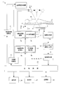
- FIG. 1 is a functional block diagram for explaining the configuration of the bone analyzing apparatus according to the first embodiment.
- the bone analysis apparatus 1 according to the first embodiment includes a top plate 2 on which a subject M that is a target of X-ray tomography is placed, and an upper portion of the top plate 2 (one surface of the top plate 2).
- X-ray tube 3 for irradiating the subject M provided on the side) with a cone-shaped X-ray beam and the lower part of the top 2 (on the other side of the top) and transmitted through the subject M
- the X-ray tube 3 and the FPD 4 are opposite to each other with the region of interest of the subject M in a state where the center axis of the FPD 4 for detecting X-rays and the center axis of the cone-shaped X-ray beam and the center point of the FPD 4 always coincide.
- the top plate 2 is disposed at a position sandwiched between the X-ray tube 3 and the FPD 4.
- the X-ray tube 3 corresponds to the radiation source of the present invention
- the FPD 4 corresponds to the detection means of the present invention.
- the synchronous movement mechanism 7 includes an X-ray tube movement mechanism 7a that moves the X-ray tube 3 in the body axis direction A with respect to the subject M, and an FPD movement mechanism that moves the FPD 4 in the body axis direction A with respect to the subject M. 7b.
- the synchronous movement control unit 8 includes an X-ray tube movement control unit 8a that controls the X-ray tube movement mechanism 7a and an FPD movement control unit 8b that controls the FPD movement mechanism 7b.
- the X-ray tube moving mechanism 7a corresponds to the radiation source moving means of the present invention
- the FPD moving mechanism 7b corresponds to the detector moving means of the present invention.
- the X-ray tube movement control unit 8a corresponds to the radiation source movement control unit of the present invention
- the FPD movement control unit 8b corresponds to the detector movement control unit of the present invention.
- the X-ray tube 3 is configured to repeatedly irradiate the subject M with a cone-shaped and pulsed X-ray beam in accordance with the control of the X-ray tube control unit 6.
- the X-ray tube 3 is provided with a collimator that collimates the X-ray beam into a cone shape that is a pyramid.
- the X-ray tube 3 and the FPD 4 generate imaging systems 3 and 4 that capture an X-ray transmission image.
- the synchronous movement mechanism 7 is configured to move the X-ray tube 3 and the FPD 4 in synchronization.
- the synchronous movement mechanism 7 linearly moves the X-ray tube 3 along a linear trajectory (longitudinal direction of the top 2) parallel to the body axis direction A of the subject M according to the control of the synchronous movement control unit 8.
- the moving direction of the X-ray tube 3 and the FPD 4 coincides with the longitudinal direction of the top 2.
- the cone-shaped X-ray beam irradiated by the X-ray tube 3 is always irradiated toward the region of interest of the subject M.
- the X-ray irradiation angle is determined by the X-ray tube 3.
- the initial angle is changed from ⁇ 20 ° to the final angle of 20 °.
- Such an X-ray irradiation angle change is performed by the X-ray tube tilting mechanism 9.
- the X-ray tube tilt control unit 10 is provided for the purpose of controlling the X-ray tube tilt mechanism 9.
- the bone analysis apparatus 1 further includes a main control unit 25 that controls the control units 6, 8, and 10 in an integrated manner, and a display unit 27 that displays the tomosynthesis image D.
- the main control unit 25 is constituted by a CPU, and realizes the control units 6, 8, 10 and the later-described units 11, 12, 13, 14, 15, 16, 17 by executing various programs. .
- storage part 23 memorize
- the console 26 is an input device used when an operator inputs bone density into the bone analysis device 1.
- the storage unit 23 corresponds to the storage unit of the present invention, and the console 26 corresponds to the input unit of the present invention.
- the synchronous movement mechanism 7 synchronizes with the linear movement of the X-ray tube 3 described above, and causes the FPD 4 provided at the lower part of the top 2 to move in the body axis direction A (the longitudinal direction of the top 2) of the subject M. Move straight ahead.
- the moving direction is opposite to the moving direction of the X-ray tube 3.
- a cone-shaped X-ray beam whose focal position and irradiation direction change as the X-ray tube 3 moves is always received by the entire surface of the X-ray detection surface of the FPD 4. Yes.
- the FPD 4 acquires, for example, 74 fluoroscopic images P0 while moving in synchronization with the X-ray tube 3 in the opposite directions.
- the imaging systems 3 and 4 are opposed to the position indicated by the alternate long and short dash line illustrated in FIG. 1 through the position indicated by the broken line with the position of the solid line as the initial position. That is, a plurality of X-ray transmission images are taken while changing the positions of the X-ray tube 3 and the FPD 4.
- the central axis of the cone-shaped X-ray beam during imaging always coincides with the center point of the FPD 4.
- the center of the FPD 4 moves straight, but this movement is in the direction opposite to the movement of the X-ray tube 3. That is, the X-ray tube 3 and the FPD 4 are moved in the body axis direction A synchronously and in directions opposite to each other.
- a symbol S in FIG. 1 represents the body side direction of the subject M.
- the synchronous movement mechanism 7 moves the FPD 4 toward the other end side in the longitudinal direction of the top plate 2 in synchronization with moving the X-ray tube 3 toward one end side in the longitudinal direction of the top plate 2. Behaves properly.
- an image generation unit 11 that generates a fluoroscopic image P0 based on a detection signal output from the FPD 4 is provided (see FIG. 1), and further downstream of the image generation unit 11 is provided. And a tomosynthesis image generation unit 12 that generates a tomosynthesis image D by synthesizing the fluoroscopic image P0.
- the image generation unit 11 corresponds to the image generation unit of the present invention
- the tomosynthesis image generation unit 12 corresponds to the tomographic image generation unit of the present invention.
- FIG. 2 is a diagram illustrating a tomographic image acquisition method of the X-ray imaging apparatus according to the first embodiment.
- a virtual plane (reference cut section MA) parallel to the top plate 2 (horizontal with respect to the vertical direction) will be described.
- the FPD 4 is synchronized with the opposite direction of the X-ray tube 3 in accordance with the irradiation direction of the cone-shaped X-ray beam B by the X-ray tube 3 so as to be projected onto the fixed points p and q of the X-ray detection surface of the FPD 4.
- a series of perspective images P ⁇ b> 0 are generated by the image generation unit 11 while being moved.
- the series of fluoroscopic images P0 the projected image of the subject M is reflected while changing the position.
- images (for example, fixed points p and q) positioned on the reference cut surface MA are accumulated and imaged as an X-ray tomographic image. It will be.
- the point I that is not located on the reference cut surface MA is reflected as a point i in a series of subject images while changing the projection position on the FPD 4.
- such a point i is blurred without forming an image when the tomosynthesis image generation unit 12 superimposes the X-ray transmission images.
- a series of fluoroscopic images P0 an X-ray tomographic image in which only an image located on the reference cut surface MA of the subject M is reflected is obtained.
- a tomosynthesis image D in which the cross-sectional image of the subject M in the reference cut surface MA is reflected is obtained.
- a similar tomographic image can be obtained even at an arbitrary cutting plane horizontal to the reference cutting plane MA.
- the projection position of the point i moves in the FPD 4, but this moving speed increases as the separation distance between the point I before projection and the reference cut surface MA increases.
- a tomosynthesis image D at a cutting plane parallel to the reference cutting plane MA is obtained. It is done.
- Such a series of subject image reconstruction is performed by the tomosynthesis image generation unit 12.
- the tomosynthesis image generation unit 12 relates to a cross section parallel to the top plate on which the subject M is placed based on the images continuously taken while moving the X-ray tube 3 and the FPD 4 with respect to the subject M.
- a tomosynthesis image D is generated.
- a tomographic image of the subject M can be obtained by an imaging method other than the above-described tomosynthesis imaging.
- tomosynthesis imaging has a feature that a tomographic image in which a trabecular bone is clearly captured can be easily captured as compared with CT imaging which is another imaging method. Therefore, it can be said that tomosynthesis imaging is an imaging method suitable for trabecular analysis.
- the generated tomosynthesis image D is sent to the image analysis units 13, 14, 15, 16, and 17.
- the image analysis units 13, 14, 15, 16, and 17 include a binarization unit 13, a trabecular shape analysis unit 14, a matrix generation unit 15, a texture analysis index calculation unit 16, and a fracture risk evaluation unit 17 shown in FIG. It is expressed as one of the functional blocks.
- the image analysis units 13, 14, 15, 16, and 17 perform various image processes on the tomosynthesis image D to perform bone analysis.
- the trabecular shape analysis unit 14, the matrix generation unit 15, and the texture analysis index calculation unit 16 correspond to the structural parameter calculation unit of the present invention
- the fracture risk evaluation unit 17 corresponds to the fracture risk evaluation unit of the present invention.
- the image analysis unit may be composed of a binarization unit 13, a trabecular shape analysis unit 14, and a fracture risk evaluation unit 17, and as shown on the right side of FIG. You may make it comprise the production
- FIG. 1 A block diagram illustrating an example of a configuration that the present invention can take.
- the image analysis unit may be composed of a binarization unit 13, a trabecular shape analysis unit 14, and a fracture risk evaluation unit 17, and as shown on the right side of FIG. You may make it comprise the production
- the image analysis unit of the present invention has a configuration in which a fracture risk evaluation value is calculated by adding a value indicating bone density to the analysis result of the tomosynthesis image D. If any analysis is added to the tomosynthesis image D, a structural parameter for evaluating the structure of the bone can be calculated by analyzing the trabecular bone reflected in the tomosynthesis image D.
- the trabecular shape analysis unit 14, the matrix generation unit 15, and the texture analysis index calculation unit 16 are all configured to calculate this structural parameter.
- various structural parameters can be calculated by changing the viewpoint of analysis. It is possible to appropriately change what structural parameter is specifically used for the fracture risk evaluation unit 17 to calculate the fracture risk evaluation value.
- both the trabecular shape analysis unit 14 and the texture analysis index calculation unit 16 may be necessary for calculating the structural parameters used by the fracture risk evaluation unit 17.
- a configuration having both the trabecular shape analysis unit 14 and the texture analysis index calculation unit 16 will be described.
- the image analysis unit of the present invention can be considered in various modes depending on the structural parameters used for the analysis.
- the fracture risk evaluation unit 17 uses the bone density to calculate the fracture risk evaluation value as shown in FIG.
- This bone density is an index representing the amount of bone mineral, and is measured by a device different from the device shown in FIG.
- Such measurement of bone density is performed by performing imaging twice while changing the energy of X-rays, and analyzing a subtraction image that is a difference between the two captured spot images.
- the subtraction image is an image obtained by photographing only the bone of the subject M, and does not include a soft tissue that is unnecessary for analysis.
- the bone density can be accurately measured by referring to the pixel value of the bone image reflected in such a subtraction image.
- the bone density is obtained based on an examination different from the tomosynthesis image capturing according to the bone analyzing apparatus 1.
- This bone density means the concentration of mineral content (bone mineral or hydroxyapatite) related to bone robustness, and is a numerical value indicating the amount of bone mineral. Therefore, the bone density is an important index for calculating the fracture risk evaluation value. Intuitively, it can be easily predicted that the higher the bone density, the lower the fracture risk assessment value. The actual fracture risk assessment is almost as expected. Therefore, it is common knowledge in the medical industry to measure bone density to know fracture risk. However, this bone density does not represent the fracture risk itself. That is, the inventor according to the present invention has found that the bone density alone is insufficient to accurately calculate the fracture risk.
- the inventor according to the present invention considered the influence of the bone structure as the reason why the fracture risk evaluation value cannot be accurately calculated only by the bone density. Even if the bone density is the same, the fracture risk assessment value should change to some extent if the internal structure of the bone is different. However, the conventional method for calculating the fracture risk evaluation value does not consider the bone structure. Therefore, the conventional method cannot accurately measure the fracture risk evaluation value.
- the present invention intends to consider not only the bone density but also the bone structure when calculating the fracture risk evaluation value. Therefore, the present invention is easy to understand when it is considered that the analysis result (structure parameter) of the tomosynthesis image D is also taken into account when calculating the fracture risk evaluation value using the bone density.
- the bone structure here is specifically the structure of the cancellous bone of the subject M, and is a cancellous structure composed of a plurality of trabecular bones in the bone.
- the tomosynthesis image D is first sent to the binarization unit 13.
- the binarization unit 13 performs binarization processing on the tomosynthesis image D, and generates a binarized tomosynthesis image D.
- the binarized tomosynthesis image D is sent to the trabecular shape analysis unit 14.
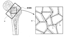
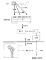
- the trabecular shape analysis unit 14 analyzes the trabecular bone reflected in the analysis range R provided in a part of the tomosynthesis image D, and calculates the result.
- FIG. 4 is a schematic diagram for explaining the operation of the trabecular shape analysis unit 14.
- the left side of FIG. 6 represents a tomographic image of the bone of the subject M shown in the tomosynthesis image D.
- the trabecular shape analysis unit 14 recognizes a part of the sponge within the bone as the analysis range R.
- FIG. 6 represents an enlarged view of the analysis range R.
- the analysis range R tomographic images of a plurality of trabeculae are shown.
- This trabecular bone forms a reticulated sponge.
- the trabecular shape analysis unit 14 analyzes the trabecular image reflected in the analysis range R and calculates various structural parameters.
- the structural parameter is a numerical value of the characteristics of a spongy structure composed of trabecular bone.
- the trabecular shape analysis unit 14 analyzes the analysis range R and calculates structural parameters such as a BV / TV value, a TSL value, and a TbTh value, for example. These structural parameters represent the trabecular shape numerically.
- the BV / TV value represents the ratio between the portion belonging to the trabecular bone in the analysis range R and the portion not.
- the BV / TV value may represent a volume ratio, but in the present invention, the BV / TV value represents an area ratio within the analysis range R.
- the bone density is a bone density obtained without considering the trabecular structure. Bone density is a quantification of how much bone mineral (hydroxyapatite) is contained in a specific compartment, so to speak, it is the density of bone mineral.
- the BV / TV value is a numerical value of how much trabecular bone is included in a specific section, and is a ratio between the space occupied by the trabecular bone and the space occupied by the gap.
- the TSL value means the total extension of the trabecular bone reflected in the analysis range R. As shown in FIG. 6, the TSL obtains a branch point n of the trabecular bone in the analysis range R by image analysis, obtains a line segment K connecting the branch points n, and totals the lengths of the line segments K. It is obtained with.
- the TbTh value means the thickness of the trabecular bone.
- the TbTh value can be obtained by obtaining the average value of the thickness of the trabecular bone belonging to the analysis range R.
- the structural parameter to be calculated by the trabecular shape analysis unit 14 is not limited to the above three.
- the structural parameter can also be calculated by texture analysis.
- This structural parameter is calculated from a viewpoint different from the analysis performed by the trabecular shape analysis unit 14.
- the structural parameters in this case are also the evaluation values when the trabecular structure is evaluated.
- texture analysis involves the matrix generation unit 15 and the texture analysis index calculation unit 16.
- ⁇ Matrix generator 15> There is a co-occurrence matrix (GLCM) as a matrix necessary for performing texture analysis. This matrix is generated by the matrix generation unit 15.
- the tomosynthesis image D generated by the tomosynthesis image generation unit 12 is sent to the matrix generation unit 15 where it is converted into GLCM.
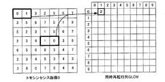
- FIG. 7 illustrates an operation in which the matrix generation unit 15 generates a GLCM based on the tomosynthesis image D.
- the left side of FIG. 7 represents the tomosynthesis image D as a two-dimensional array of pixel values. For simplicity of explanation, it is assumed that the pixel values of each pixel constituting the tomosynthesis image D have ten values from 0 to 9.
- the number of rows and the number of columns of GLCM generated from the tomosynthesis image D both match the number of pixel values that the pixel value of the pixel can take. Since each pixel constituting the tomosynthesis image D has one of 10 pixel values, the GLCM generated from the tomosynthesis image D is a two-dimensional matrix of 10 rows and 10 columns.
- the matrix generating unit 15 completes the GLCM by assigning numerical values to 100 elements constituting the GLCM that is a 10 ⁇ 10 matrix. It is determined based on the pixel value of the tomosynthesis image D what value is to be entered for each element.
- FIG. 7 shows that the matrix generation unit 15 is going to determine the numerical value of the element p (0, 1) located in the row meaning 0 in each row of GLCM and the row meaning 1 in each column. Yes.
- the matrix generation unit 15 counts the number of pixel pairs in which the pixel value 0 and the pixel value 1 are arranged adjacent to each other in the tomosynthesis image D, and calculates the count number to the element p (0, 1) of the GLCM. ).
- the value of the element p (0, 1) is 2. Since the arbitrary element p (a, b) in this GLCM is equal to the element p (b, a), the value of the element p (1, 0) in GLCM is also 2.
- the matrix generation unit 15 performs the same operation over the entire area of the GLCM, and determines all the elements of the matrix based on the tomosynthesis image D. Thus, the matrix generation unit 15 completes the GLCM based on the tomosynthesis image D.
- FIG. 8 shows a state in which the matrix generation unit 15 generates a GLCM based on the tomosynthesis image D.
- the generated GLCM increases as the number of pixel values that the pixel of the tomosynthesis image D can take increases.
- GLCM is a matrix having symmetry, and is a matrix in which the values of overlapping elements are the same when folded in half by a diagonal line shown by a dotted line in FIG.
- the matrix generation unit 15 is a pair of two pixels having a combination of predetermined pixel values among the pixels constituting the analysis range provided in a part of the tomosynthesis image D, and the pixels are separated by a predetermined distance.
- a GLCM co-occurrence matrix
- the matrix generation unit 15 generates GLCM for the cancellous bone of each part of the bone reflected in the tomosynthesis image D.
- each part of the bone includes a bone neck and a diaphysis.
- FIG. 8 shows how GLCM is generated for the bone neck.
- the GLCM is sent to the texture analysis index calculation unit 16.
- the texture analysis index calculation unit 16 can calculate the texture analysis index by performing various operations on the GLCM. Examples of the texture analysis index that can be calculated by the texture analysis index calculation unit 16 include the following.
- P (i, j) in the expression is the value of the element in the i-th row and j-th column in GLCM
- ⁇ i and ⁇ j are the total of the elements for the i-th row and j-th column, respectively
- N g is the tomosynthesis image
- D Is the average value
- ⁇ x and ⁇ y are the average values in the row direction and the column direction
- ⁇ x and ⁇ y are the standard deviations in the row direction and the column direction, respectively.
- these texture analysis indices ASM (Angular Second Moment), CNT (Contrast), COR (Correlation), VAR (Variance), IDM (Inverse Differential Moment, Inverse Differential Moment).
- ENT Entropy
- DIS is a texture analysis index called dissimilarity or dissimilarity
- HOM is a texture analysis index called uniformity or homogeneity.
- Haralick RM. et al Textural Features for Image Classification. IEEE Transactions on Systems Man and Cybernetics 1973; 6: 610-621.
- the texture analysis index calculation unit 16 calculates the texture analysis index by performing the above-described various calculations on the GLCM.
- the type and number of texture indices calculated by the texture analysis index calculator 16 can be changed as appropriate.
- the number of texture analysis indices may be three or less.
- the texture analysis index calculation unit 16 performs texture analysis based on GLCM (co-occurrence matrix) and calculates a texture analysis index.
- This texture analysis index is a kind of structural parameter of the present invention.
- the trabecular shape analysis unit 14 and the texture analysis index calculation unit 16 calculate the structural parameters based on the tomosynthesis image of the subject M.
- the various structural parameters calculated in this way are sent to the fracture risk evaluation unit 17.
- the fracture risk evaluation unit 17 calculates a fracture risk evaluation value based on an estimation formula.
- bone density is required in addition to the above structural parameters. This bone density is measured in advance by subtraction imaging before imaging the tomosynthesis image D related to the structural parameter. The surgeon can input this bone density through the console 26.
- the fracture risk evaluation unit 17 evaluates the bone density indicating the density of the substance related to the robustness of the bone of the subject M and the structure of the trabecular bone constituting the bone of the subject M. As a result, the fracture risk evaluation value indicating the risk of fracture of the bone is calculated.
- the fracture risk evaluation unit 17 calculates the fracture risk evaluation value by substituting the bone density input by the operator through the console 26 and the structural parameter that is the analysis result of the tomosynthesis image D into the estimation formula.
- the estimation formula used for calculation by the fracture risk evaluation unit 17 is, for example, as follows. The lower the fracture risk evaluation value is, the lower the risk of fracture.
- P k B ⁇ B + k C ⁇ C + N (1)
- P is a fracture risk evaluation value
- B is a bone density
- C is a structural parameter
- N is a constant.
- k B and k C are coefficients by which each parameter is multiplied.
- the common point of the estimation formula in the present invention is that the estimation formula includes a term related to the bone density and a term related to the structural parameter. That is, the fracture risk evaluation unit 17 is configured to calculate the fracture risk evaluation value using an estimation formula indicating the relationship between the fracture risk evaluation value, the bone density, and the structural parameter.
- the subject is actually analyzed to calculate fracture risk evaluation values, bone density, and structural parameters.
- the fracture risk evaluation value of the subject is obtained by CT finite element method (FEM) simulation.
- FEM finite element method
- a 3D image of cancellous bone is acquired by CT imaging, and a three-dimensional model generated based on this image is generated. Then, what happens when a physical load is applied to the three-dimensional model is simulated, and it is estimated how far the structure can withstand without breaking.
- the estimated value representing this estimation result is the fracture risk evaluation value.
- the fracture risk evaluation value can be measured by such a method, it is not easy to carry out the examination of the subject M because the technique is complicated and complicated calculation is required.
- the bone density of the femoral neck can be obtained by taking a subtraction image of the femur as described above.
- Bone density means the density of bone mineral that achieves bone strength.
- the femoral neck structural parameters can be obtained by taking a tomosynthesis image as described above.
- the structural parameter is an evaluation value for evaluating the state of the trabecular bone.
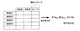
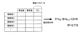
- FIG. 9 shows a table in which the various parameters thus obtained are arranged for each subject M.
- the estimation formula is finally decided.
- a plurality of estimation formulas having different structure parameters are prepared, and the one that can estimate the fracture risk evaluation value most accurately is selected.
- an estimation formula using BV / TV values and an estimation formula using TSL values are obtained as structural parameters, and a test is performed to determine which estimation formula is better.
- multiple regression analysis is performed on the BV / TV value. Multiple regression analysis is a statistical method of calculating a mathematical formula that predicts one parameter from a plurality of parameters. In the multiple regression analysis, two parameters and one parameter that seems to be correlated with them are determined, and a statistical analysis is performed to obtain an estimation formula.
- the estimation formula has a structure in which one parameter is output when two parameters are input. Two parameters related to input are called independent variables, and parameters related to outputs are called dependent variables.
- FIG. 10 shows the fracture risk evaluation value, bone density, and BV / TV value extracted from the table shown in FIG.
- the independent variables are the bone density and the BV / TV value
- the dependent variable is the fracture risk evaluation value.
- the mathematical expression as described in (1) above and an R 2 value indicating the reliability of estimation are calculated. In general, the closer the R 2 value is to 1, the higher the reliability of the estimation formula. High reliability of the estimation formula means that there is a small discrepancy in the numerical value seen between the result of estimation using the estimation formula and the actual data.
- FIG. 11 shows a state in which an estimation formula for the TSL value is calculated.
- FIG. 11 shows fracture risk evaluation values, bone density, and TSL values extracted from the table shown in FIG.
- the independent variables are the bone density and the TSL value
- the dependent variable is the fracture risk evaluation value.
- the R 2 value is a unique value representing the reliability of each estimation formula. If the R 2 values are compared between the estimation formulas, it can be determined which estimation formula is suitable for calculating the fracture risk evaluation value. In the example of FIGS. 10 and 11, the estimation formula related to the BV / TV value is suitable for the calculation of the fracture risk evaluation value. This is because the R 2 value related to the BV / TV value is larger than the R 2 value related to the TSL value.
- the estimation formula of the present invention is selected so that the fracture risk evaluation value can be estimated most accurately from a plurality of estimation formulas having different structural parameters.
- the estimation formula is calculated by performing multiple regression analysis using one structural parameter as an independent variable in addition to the bone density.
- the estimation formula may be calculated by performing multiple regression analysis using the parameters as independent variables.
- the R 2 value of this estimation formula was 0.818. This estimate is higher than the estimated equation R 2 value obtained when a fracture risk evaluation value and regression analysis only bone density. Therefore, it was possible to obtain a more reliable result when the fracture risk evaluation value was calculated using the bone density and the BV / TV value.
- the fracture risk evaluation value When attempting to examine the subject M, it is difficult to calculate the fracture risk evaluation value by the CT finite element method.
- the fracture risk evaluation value can be simply calculated by calculating the bone density and the structural parameters that are relatively easy to measure. Can be calculated.
- the calculated fracture risk evaluation value has high reliability as indicated by the R 2 value in equation (2).
- FIG. 13 summarizes the outline of the present invention.
- preparation for bone analysis according to the present invention first, CT imaging, subtraction imaging, and tomosynthesis imaging are performed on a specimen, and image analysis is performed on each of the obtained images.
- image analysis results multiple regression analysis is performed using the bone density and structural parameters as independent variables and the fracture risk evaluation value as a dependent variable, and an estimation formula is calculated.
- the estimation formula is most reliable among the several calculated by changing the independent variable is estimated formula (R 2 value is high) has become one.
- the estimation formula for the bone neck is calculated.
- the estimation formula prepared by the preparation is stored in the storage unit 23.
- subtraction imaging is performed in advance to calculate bone density.
- This bone density is input to the bone analyzing apparatus 1 by the operator through the console 26.
- tomosynthesis imaging is performed using the bone analyzing apparatus 1.
- the fracture risk evaluation unit 17 calculates a fracture risk evaluation value representing bone strength based on the estimation formula stored in the storage unit 23, the input bone density, and the calculated structural parameter.
- the bone density in the present invention is positioned to partially explain the risk of fracture. That is, in the present invention, the bone density is important for knowing the fracture risk, but is considered to be insufficient for accurate fracture risk evaluation. This situation is the same for the structural parameters. That is, in the present invention, the structural parameter is important for knowing the fracture risk, but is considered to be insufficient for accurate fracture risk evaluation.
- the fracture risk is comprehensively evaluated based not only on the bone density but also on the structural parameters for evaluating the structure of the trabecular bone. If comprised in this way, since a fracture risk can be evaluated from two viewpoints of a bone density and a structure of a trabecular bone, a fracture risk can be evaluated more correctly.
- the structural parameter is calculated based on the tomosynthesis image of the subject M as described above, the structural parameter can be calculated based on the image in which the trabecular bone is clearly reflected, so that the fracture risk can be more accurately detected. It becomes possible to evaluate.
- FIG. 14 shows the relationship between the bone density calculated by the X-ray image analysis and the actual bone strength.
- the bone density is treated as representing bone strength. That is, it is assumed that there is a correlation between the bone density calculated by the X-ray image analysis and the bone strength.
- FIG. 14 shows how correct this assumption is.
- the bone density (BMD) obtained by image analysis of a part of the sample bone and the bone strength measured by applying pressure to that part. The result is plotted. Therefore, the FEM bone strength on the vertical axis cannot be measured with an actual subject.
- FIG. 14 it can be seen that there is a positive correlation between bone density and bone strength as an overall trend. However, the results are somewhat different and the R 2 value obtained by regression analysis is 0.747.
- FIG. 15 shows a plot obtained with the bone analyzing apparatus according to the present invention.
- the FEM bone strength prediction value (N) on the horizontal axis is obtained by performing the calculation of the cervical BMD value of the sample bone and the BV / TV value, which is a structural parameter, in each part of the sample bone and performing regression analysis on the obtained results. Based on the obtained mathematical formula, the FEM bone strength in each part of the sample bone is predicted.
- k B in the estimation formula described in FIG. 13 was 10,759
- k C was 11,430
- N was ⁇ 3,278. This estimation formula is obtained by image analysis of bone neck and bone strength measurement.
- FIG. 15 shows the FEM bone strength prediction value obtained by image analysis of the bone neck of the sample bone, the bone strength measured by applying pressure to that portion, and the result plotted. . Therefore, the FEM bone strength on the vertical axis cannot be measured with an actual subject. As a whole, it can be seen that there is a positive correlation between bone density and bone strength.
- the R 2 value obtained by regression analysis was 0.818.
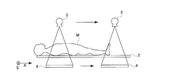
- a tomographic image can be taken while the X-ray tube 3 and the FPD 4 are moved in the body axis direction A of the subject M while maintaining the mutual positional relationship.
- the synchronous movement mechanism 7 moves the FPD 4 toward one end side in the longitudinal direction of the top plate 2 in synchronization with moving the X-ray tube 3 toward one end side in the longitudinal direction of the top plate 2.
- the configuration of the X-ray imaging apparatus according to the second embodiment is the same as the functional block diagram in FIG. 1 differs from the first embodiment in that the FPD 4 moves following the X-ray tube 3 (see FIG. 16) and the X-ray tube 3 does not tilt. Therefore, in the second embodiment, the X-ray tube tilt mechanism 9 and the X-ray tube tilt control unit 10 in FIG. 1 are not necessarily required.
- X-rays are intermittently emitted while moving with respect to the subject M in a state where the imaging systems 3 and 4 maintain the relative positions. That is, every time one irradiation is completed, the X-ray tube 3 moves in the body axis direction A of the subject M and again performs X-ray irradiation. In this way, a plurality of transmission images are acquired, and a processed image (a long transmission image described later) of the transmission image is reconstructed into a tomographic image by the filter back projection method.
- the completed tomographic image is an image in which a tomographic image obtained by cutting the subject M with a certain cut surface is reflected.
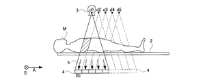
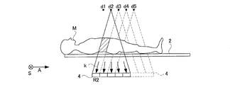
- FIG. 17 shows the position of the FPD 4 when the focal point of the X-ray tube 3 that irradiates the X-rays is at the position d1.
- a transmission image is captured every time the X-ray tube 3 and the FPD 4 move in this direction relative to the top 2 by a width of 1/5 of the FPD 4 in the body axis direction A of the subject M. To do.
- the incident angle of the X-ray with respect to the FPD 4 is as shown by an arrow.
- the divisions are different from each other. Pay attention to one of the directions k. Since the X-rays traveling in the direction k pass through the hatched portion of the subject M and are reflected in the FPD 4, the diagonal lines of the subject M are included in the FPD 4 in which the X-rays in the direction k are incident. The part is reflected. In the transmission image, a portion corresponding to this division is defined as a fragment R1.
- FIG. 18 shows the position of the FPD 4 when the focal point for irradiating the X-ray of the X-ray tube 3 is at the position of d2 moved from d1 by a width of 1/5 of FPD4. Since the positional relationship between the X-ray tube 3 and the FPD 4 does not change, the FPD 4 should also have a division in which the X-rays traveling in the direction k are reflected in the imaging at this time, and the X-rays in the direction k The hatched portion of the subject M is reflected in the divisional area of the FPD 4 on which is incident. In the transmission image, a portion corresponding to this division is referred to as a fragment R2.
- the X-ray is taken when the whole body of the subject M is irradiated in a certain direction k. Images can be obtained. This image is called a long transmission image.
- the bone analyzing apparatus generates a long transmission image in directions other than the direction k in the tomosynthesis image generation unit 12.
- the tomosynthesis image generation unit 12 generates a tomosynthesis image D when the subject M is cut at a predetermined cutting position based on a plurality of long transmission images having different directions in which the subject M is projected.
- Example 2 The analysis performed on the tomosynthesis image D in Example 2 is the same as in Example 1, and finally a fracture risk evaluation value is calculated.
- a long image acquired by virtually performing slot shooting is shot, and a tomosynthesis image D is shot from these images.
- a radiation imaging apparatus that can acquire a tomosynthesis image D captured over a wide range.
- the present invention is not limited to the above-described configuration, and can be modified as follows.
- the texture analysis index is specified, but the fracture risk evaluation value can also be calculated using another texture analysis index that can be derived from the co-occurrence matrix. That is, texture analysis indices other than those presented by Harlick et al. Exemplified in the above-described embodiment can also be used.
- the fracture risk evaluation value is expressed by a continuous numerical value, but the present invention is not limited to this configuration.
- the fracture risk evaluation unit 17 may express whether the risk of fracture is high or low by properly using two values.
- the fracture risk evaluation value means a flag for distinguishing the risk of fracture.
- the fracture risk evaluation value may be determined so that the fracture risk can be evaluated at a predetermined stage.
- the fracture risk evaluation unit 17 may be configured to operate by reading the bone density stored in the storage unit 23.
- the matrix generation unit 15 of the above-described embodiment operates to count the number of pixel pairs adjacent to each other in the tomosynthesis image D
- the present invention is not limited to this configuration. That is, as shown in FIG. 18, the co-occurrence matrix may be generated by counting the number of pixel pairs separated by a predetermined distance.
- FIG. 20 illustrates a state in which the matrix generation unit 15 counts a pair of pixels separated by a width of one pixel in which both pixel values are 4.
- the trabecular shape analysis unit 14 calculates the structural parameters such as the BV / TV value, but the present invention is not limited to this configuration.
- structural parameters relating to evaluation of other trabeculae such as the number of trabeculae and anisotropy may be calculated, and the fracture risk evaluation unit 17 may calculate the fracture risk based on the structural parameters. .
- the data indicating the relationship between the fracture risk evaluation value, the bone density, and the structural parameter is in the form of a mathematical formula, but the present invention is not limited to this configuration.
- the data indicating the relevance may be in the form of a database in which each parameter is managed as a table. Such a database is obtained by actually measuring or simulating each parameter.
- the fracture risk evaluation unit 17 recognizes the combination of the input bone density and the structural parameter, and searches for the combination from the database to thereby calculate the fracture risk corresponding to this combination. Operates by obtaining an evaluation value.
- the structural parameter is calculated based on the imaging result of the tomosynthesis apparatus, but the present invention is not limited to this configuration.
- the structural parameters may be calculated based on imaging results other than the tomosynthesis apparatus, such as imaging results of the CT apparatus.
- the bone density is calculated by subtraction imaging, but is not limited to the configuration of the present invention box.
- the bone density may be calculated based on the imaging result of the tomosynthesis device.
- the present invention is suitable for the medical field.
Landscapes
- Health & Medical Sciences (AREA)
- Life Sciences & Earth Sciences (AREA)
- Engineering & Computer Science (AREA)
- Medical Informatics (AREA)
- Public Health (AREA)
- Pathology (AREA)
- General Health & Medical Sciences (AREA)
- Biomedical Technology (AREA)
- Molecular Biology (AREA)
- Veterinary Medicine (AREA)
- Nuclear Medicine, Radiotherapy & Molecular Imaging (AREA)
- Radiology & Medical Imaging (AREA)
- High Energy & Nuclear Physics (AREA)
- Heart & Thoracic Surgery (AREA)
- Biophysics (AREA)
- Surgery (AREA)
- Animal Behavior & Ethology (AREA)
- Physics & Mathematics (AREA)
- Optics & Photonics (AREA)
- Computer Vision & Pattern Recognition (AREA)
- Physiology (AREA)
- Orthopedic Medicine & Surgery (AREA)
- Dentistry (AREA)
- Oral & Maxillofacial Surgery (AREA)
- Human Computer Interaction (AREA)
- Data Mining & Analysis (AREA)
- Databases & Information Systems (AREA)
- Epidemiology (AREA)
- Primary Health Care (AREA)
- Apparatus For Radiation Diagnosis (AREA)
Abstract
Description
すなわち、本発明に係る骨解析装置は、被検体の骨密度および骨梁から構成される海綿状構造の特性を数値化した構造パラメータに基づいて被検体の骨が骨折を起こすリスクを示す骨折リスク評価値を算出する骨折リスク評価手段を備えることを特徴とするものである。
生成されたトモシンセシス画像Dは、画像解析部13,14,15,16,17に送られる。この画像解析部13,14,15,16,17は、図3に示す二値化部13,骨梁形状解析部14,行列生成部15,テクスチャ解析指標算出部16および骨折リスク評価部17をまとめ機能ブロックの一つとして表現したものとなっている。画像解析部13,14,15,16,17は、トモシンセシス画像Dに種々の画像処理を施して骨解析を行う。骨梁形状解析部14,行列生成部15,テクスチャ解析指標算出部16は、本発明の構造パラメータ算出手段に相当し、骨折リスク評価部17は本発明の骨折リスク評価手段に相当する。
トモシンセシス画像Dは、まず二値化部13に送出される。二値化部13は、トモシンセシス画像Dに二値化処理を施し、二値化されたトモシンセシス画像Dを生成する。この二値化されたトモシンセシス画像Dは、骨梁形状解析部14に送出される。骨梁形状解析部14は、トモシンセシス画像Dの一部に設けられた解析範囲Rに写り込む骨梁を解析してその結果を算出する。図4は、骨梁形状解析部14の動作を説明する模式図である。図6の左側はトモシンセシス画像Dに写り込んだ被検体Mの骨の断層像を表している。骨梁形状解析部14は、骨の内部の海綿質の一部を解析範囲Rと認識する。
テクスチャ解析を行う際に必要となる行列として同時生起行列(GLCM)がある。この行列は行列生成部15により生成される。トモシンセシス画像生成部12が生成したトモシンセシス画像Dは、行列生成部15に送出され、そこでGLCMに変換される。図7は、行列生成部15がトモシンセシス画像Dに基づいてGLCMを生成する動作を説明している。図7の左側は、トモシンセシス画像Dを画素値の2次元配列として表している。説明の簡単のため、トモシンセシス画像Dを構成する各画素の画素値は、0から9までの10通りの値をとるものとする。
GLCMは、テクスチャ解析指標算出部16に送出される。テクスチャ解析指標算出部16は、GLCMに種々の演算を実行することでテクスチャ解析指標を算出することが可能である。テクスチャ解析指標算出部16が算出できるテクスチャ解析指標は、例えば次のようなものがある。式中のp(i,j)とは、GLCMにおけるi行j列目の要素の値、Σi,Σjは、それぞれi行、j列についての要素の合計、Ngは、トモシンセシス画像Dの画素が取り得る画素値の数、μは平均値、μx,μyは、それぞれ行方向、列方向の平均値、σx,σyは、それぞれ行方向、列方向の標準偏差を表している。なお、これらテクスチャ解析指標ASM(Angular Second Moment:アングラーセカンドモーメント),CNT(Contrast:コントラスト),COR(Correlation:コリレーション),VAR(Variance:バリアンス),IDM(Inverse Difference Moment,インバースディファレンシャルモーメント),ENT(Entropy,エントロピー)の各々は、1973年にHarlickらが下記の文献(A)で提唱した14種類のパラメータのうちの一部である。また、DISは非類似度またはディシミラレィティと呼ばれるテクスチャ解析指標で、HOMは、一様性またはホモジェネイティと呼ばれるテクスチャ解析指標である。
(A)Haralick RM. et al. Textural Features for Image Classification. IEEE Transactions on Systems Man and Cybernetics 1973;6:610-621.

P=kB・B+kC・C+N …(1)
ここで、Pは、骨折リスク評価値であり、Bは骨密度であり、Cは構造パラメータであり、Nは定数である。kB,kCは、各パラメータに乗じられる係数である。構造パラメータとしては、BV/TV値などの骨梁形状解析部14が算出したものであってもよいし、ASMなどのテクスチャ解析指標算出部16が算出したものであってもよい。また、推定式を例えば以下に示すように2つ以上の構造パラメータを含んだものとすることもできる。
P=kB・B+kC1・C1+kC2・C2+…+N
このように、本発明においては推定式が構造パラメータのどれを何個含むかを適宜選択することができる。本発明における推定式の共通点は、推定式が骨密度に関する項を含むことと、構造パラメータに関する項を含むことである。つまり、骨折リスク評価部17は、骨折リスク評価値、骨密度および前記構造パラメータの関連性を示す推定式を用いて骨折リスク評価値を算出する構成となっている。
骨折リスク評価部17が動作に用いる推定式をどのように決定するのかについて説明する。推定式を完成させるには、数ある構造パラメータのうちどれを用いるのかと、各係数と定数の決定とを骨の部位ごとに行わなければならない。このような推定式は、被検体Mの骨梁解析に先立って決められる。推定式の決定方法としては回帰式を用いた方法が利用できる。
最後に、本発明の効果を実証したのでこれについて説明する。すなわち、実証として39例の複数の糖尿病患者において、実際に大腿骨頸部の骨折リスク評価値、骨密度、構造パラメータを算出がなされた。本発明の効果の検定に糖尿病患者を用いるのは、骨密度だけで正確な骨折リスク評価値を算出するのが難しいとされているから、本発明の効果がより顕著に表れると考えられるからである。
P=kB・B+N
P=10,759×B+11,430×C-3,278…(2)
この推定式のR2値は0.818であった。この推定値は、骨折リスク評価値を骨密度のみで回帰分析したときに得られる推定式のR2値よりの高い。したがって、骨折リスク評価値を骨密度およびBV/TV値を用いて算出した方がより信頼性の高い結果を得ることができた。
図14,図15は、本発明の効果を説明している。図14は、X線画像解析により算出された骨密度と実際の骨強度の関連性を示している。従来構成では骨密度が骨強度を表すものとして扱われている。つまり、X線画像解析により算出された骨密度と骨強度には相関があるというのが前提である。図14はこの前提がどの程度正しいかを示しているもので、標本骨のある部分について画像解析をすることで得られた骨密度(BMD)と、その部分に圧力をかけて骨強度を実測し、その結果をプロットしたものとなっている。従って縦軸に係るFEM骨強度は、実際の被検体で測定できるものではない。図14を参照すると、全体的な傾向として骨密度と骨強度には正の相関があることがわかる。しかし、結果はややばらついたものとなり、回帰分析で得られるR2値は0.747である。
4 FPD(検出手段)
7a X線管移動機構(放射線源移動手段)
7b FPD移動機構(検出器移動手段)
8a X線管移動制御部(放射線源移動制御手段)
8b FPD移動制御部(検出器移動制御手段)
11 画像生成部(画像生成手段)
12 トモシンセシス画像生成部(断層画像生成手段)
14 骨梁形状解析部(構造パラメータ算出手段)
15 行列生成部(構造パラメータ算出手段)
16 テクスチャ解析指標算出部(構造パラメータ算出手段)
17 骨折リスク評価部(骨折リスク評価手段)
23 記憶部(記憶手段)
26 操作卓(入力手段)
Claims (10)
- 被検体の骨密度および骨梁から構成される海綿状構造の特性を数値化した構造パラメータに基づいて被検体の骨が骨折を起こすリスクを示す骨折リスク評価値を算出する骨折リスク評価手段を備えることを特徴とする骨解析装置。
- 請求項1に記載の骨解析装置において、
前記骨折リスク評価手段は、前記骨折リスク評価値、前記骨密度および前記構造パラメータの関連性を示すデータを用いて前記骨折リスク評価値を算出することを特徴とする骨解析装置。 - 請求項1に記載の骨解析装置において、
被検体のトモシンセシス画像に基づいて前記構造パラメータを算出する構造パラメータ算出手段を備えていることを特徴とする骨解析装置。 - 請求項3に記載の骨解析装置において、
前記骨密度は、前記トモシンセシス画像の撮影とは異なる検査に基づいて取得されたものであることを特徴とする骨解析装置。 - 請求項1に記載の骨解析装置において、
術者が前記骨密度を入力する入力手段を備えていることを特徴とする骨解析装置。 - 請求項1に記載の骨解析装置において、
前記骨密度を記憶する記憶手段を備えていることを特徴とする骨解析装置。 - 請求項3に記載の骨解析装置において、
前記構造パラメータ算出手段は、前記構造パラメータの算出に係る関心部位内の骨成分とそれ以外の部分との比を示すBV/TV値、骨梁総延長を表すTSL値、骨梁の幅を表すTbTh値のいずれかを構造パラメータとして算出することを特徴とする骨解析装置。 - 請求項3に記載の骨解析装置において、
前記構造パラメータ算出手段として前記構造パラメータの算出に係る関心部位を構成する各画素のうち所定の画素値の組み合わせを有する2つの画素のペアで画素同士が所定の距離だけ離間しているものが関心部位において何回現れるかを各画素値の組み合わせごとに数えて同時生起行列を生成する同時生起行列生成手段と、
同時生起行列に基づいてテクスチャ解析を行い前記構造パラメータであるテクスチャ解析指標を構造パラメータとして算出するテクスチャ解析手段とを備えていることを特徴とする骨解析装置。 - 請求項8に記載の骨解析装置において、
前記テクスチャ解析手段が算出するテクスチャ解析指標として、コリレーション、ディシミラレィティ、コントラスト、ホモジェネイティ、エントロピー、アングラーセカンドモーメント、バリアンス、インバースディファレンシャルモーメントのうちの1つまたは複数が選択されていることを特徴とする骨解析装置。 - 請求項3に記載の骨解析装置において、
放射線を照射する放射線源と、
前記放射線源を被検体に対し移動させる放射線源移動手段と、
前記放射線源移動手段を制御する放射線源移動制御手段と、
被検体を透過した放射線を検出する検出手段と、
前記検出手段を被検体に対し移動させる検出器移動手段と、
前記検出器移動手段を制御する検出器移動制御手段と、
前記検出手段の出力を基に画像を生成する画像生成手段と、
前記放射線源および前記検出手段を被検体に対して移動させながら連写された画像を基に前記トモシンセシス画像を生成する断層画像生成手段を備えていることを特徴とする骨解析装置。
Priority Applications (3)
| Application Number | Priority Date | Filing Date | Title |
|---|---|---|---|
| US15/550,527 US20180020999A1 (en) | 2015-02-13 | 2016-02-12 | Bone analyzing device |
| CN201680010108.6A CN107205709A (zh) | 2015-02-13 | 2016-02-12 | 骨分析装置 |
| JP2016574865A JP6515936B2 (ja) | 2015-02-13 | 2016-02-12 | 骨解析装置 |
Applications Claiming Priority (2)
| Application Number | Priority Date | Filing Date | Title |
|---|---|---|---|
| JP2015026647 | 2015-02-13 | ||
| JP2015-026647 | 2015-11-30 |
Publications (1)
| Publication Number | Publication Date |
|---|---|
| WO2016129682A1 true WO2016129682A1 (ja) | 2016-08-18 |
Family
ID=56614410
Family Applications (1)
| Application Number | Title | Priority Date | Filing Date |
|---|---|---|---|
| PCT/JP2016/054164 Ceased WO2016129682A1 (ja) | 2015-02-13 | 2016-02-12 | 骨解析装置 |
Country Status (4)
| Country | Link |
|---|---|
| US (1) | US20180020999A1 (ja) |
| JP (1) | JP6515936B2 (ja) |
| CN (1) | CN107205709A (ja) |
| WO (1) | WO2016129682A1 (ja) |
Cited By (6)
| Publication number | Priority date | Publication date | Assignee | Title |
|---|---|---|---|---|
| EP3461412A1 (en) * | 2017-09-29 | 2019-04-03 | General Electric Company | System and method for dxa tomo-based finite element analysis of bones |
| JP2020010904A (ja) * | 2018-07-20 | 2020-01-23 | コニカミノルタ株式会社 | 医用画像処理装置及び医用画像撮影システム |
| WO2023054287A1 (ja) * | 2021-10-01 | 2023-04-06 | 富士フイルム株式会社 | 骨疾患予測装置、方法およびプログラム、学習装置、方法およびプログラム並びに学習済みニューラルネットワーク |
| US11769250B2 (en) | 2019-09-11 | 2023-09-26 | Fujifilm Corporation | Medical care support device, medical care support method, and medical care support program |
| EP4527297A1 (en) | 2023-09-20 | 2025-03-26 | FUJI-FILM Corporation | Image processing device, image processing method, and image processing program |
| US12471867B2 (en) | 2022-09-13 | 2025-11-18 | Fujifilm Corporation | Image processing device, image processing method, and image processing program |
Families Citing this family (8)
| Publication number | Priority date | Publication date | Assignee | Title |
|---|---|---|---|---|
| CN108538393B (zh) * | 2018-04-02 | 2021-12-10 | 重庆邮电大学 | 基于大数据的骨质质量评估专家系统及预测模型建立方法 |
| JP2019180906A (ja) * | 2018-04-11 | 2019-10-24 | 富士フイルム株式会社 | 画像処理装置、放射線画像撮影システム、画像処理方法、及び画像処理プログラム |
| CN117393146A (zh) * | 2018-09-10 | 2024-01-12 | 京瓷株式会社 | 推定装置、系统以及推定方法 |
| US10762632B2 (en) * | 2018-09-12 | 2020-09-01 | Siemens Healthcare Gmbh | Analysis of skeletal trauma using deep learning |
| CN111192247B (zh) * | 2019-12-27 | 2023-01-20 | 中国人民解放军陆军军医大学第二附属医院 | 一种骨髓组织识别装置、系统及方法 |
| CN111724357B (zh) * | 2020-06-09 | 2023-05-16 | 四川大学 | 基于数字放射图像及支持向量回归的手臂骨密度测量方法 |
| JP7546497B2 (ja) * | 2021-02-09 | 2024-09-06 | 富士フイルム株式会社 | 運動器疾患予測装置、方法およびプログラム、学習装置、方法およびプログラム並びに学習済みニューラルネットワーク |
| CN120998506A (zh) * | 2025-08-08 | 2025-11-21 | 湖南隽禾科技有限公司 | 结合多维影像技术与人工智能的骨折预测系统 |
Citations (7)
| Publication number | Priority date | Publication date | Assignee | Title |
|---|---|---|---|---|
| JPH09508813A (ja) * | 1993-11-29 | 1997-09-09 | アーチ ディヴェロプメント コーポレイション | コンピュータによる骨のx線写真解析の方法およびシステム |
| JPH09327462A (ja) * | 1996-06-10 | 1997-12-22 | Asuka B F Kk | 骨評価装置用の踵骨部測定体 |
| JP2003514641A (ja) * | 1999-11-24 | 2003-04-22 | ホロジック, インコーポレイテッド | 将来の骨折危険性を決定する装置及び方法 |
| JP2007524438A (ja) * | 2003-03-25 | 2007-08-30 | イメージング セラピューティクス,インコーポレーテッド | 放射線画像処理技術における補償の方法 |
| JP2007303943A (ja) * | 2006-05-10 | 2007-11-22 | Osaka Univ | 骨粗鬆症の評価方法 |
| JP2013027608A (ja) * | 2011-07-29 | 2013-02-07 | Shimadzu Corp | 骨梁解析装置 |
| JP2013141477A (ja) * | 2012-01-06 | 2013-07-22 | Ryukoku Univ | 骨折リスク評価方法 |
Family Cites Families (14)
| Publication number | Priority date | Publication date | Assignee | Title |
|---|---|---|---|---|
| US5172695A (en) * | 1990-09-10 | 1992-12-22 | Cann Christopher E | Method for improved prediction of bone fracture risk using bone mineral density in structural analysis |
| EP0905638A1 (en) * | 1994-08-29 | 1999-03-31 | Torsana A/S | A method of estimation |
| CA2201057C (en) * | 1996-03-29 | 2002-01-01 | Kenji Morimoto | A method of processing a sectional image of a sample bone including a cortical bone portion and a cancellous bone portion |
| JP3258233B2 (ja) * | 1996-03-29 | 2002-02-18 | 帝人株式会社 | 骨計測方法 |
| US6442287B1 (en) * | 1998-08-28 | 2002-08-27 | Arch Development Corporation | Method and system for the computerized analysis of bone mass and structure |
| JP3499761B2 (ja) * | 1998-10-22 | 2004-02-23 | 帝人株式会社 | 骨画像処理方法及び骨強度評価方法 |
| US7660453B2 (en) * | 2000-10-11 | 2010-02-09 | Imaging Therapeutics, Inc. | Methods and devices for analysis of x-ray images |
| US6975894B2 (en) * | 2001-04-12 | 2005-12-13 | Trustees Of The University Of Pennsylvania | Digital topological analysis of trabecular bone MR images and prediction of osteoporosis fractures |
| US8965075B2 (en) * | 2002-09-16 | 2015-02-24 | Imatx, Inc. | System and method for predicting future fractures |
| US7840247B2 (en) * | 2002-09-16 | 2010-11-23 | Imatx, Inc. | Methods of predicting musculoskeletal disease |
| EP1583467B1 (en) * | 2003-01-07 | 2010-10-13 | Imaging Therapeutics, Inc. | Device for predicting musculoskeletal disease |
| US20080058613A1 (en) * | 2003-09-19 | 2008-03-06 | Imaging Therapeutics, Inc. | Method and System for Providing Fracture/No Fracture Classification |
| US9848818B1 (en) * | 2013-08-09 | 2017-12-26 | O.N.Diagnostics, LLC | Clinical assessment of fragile bone strength |
| US9532761B2 (en) * | 2014-01-14 | 2017-01-03 | Cyberlogic, Inc. | Method and system for bone fracture risk assessment |
-
2016
- 2016-02-12 US US15/550,527 patent/US20180020999A1/en not_active Abandoned
- 2016-02-12 CN CN201680010108.6A patent/CN107205709A/zh active Pending
- 2016-02-12 JP JP2016574865A patent/JP6515936B2/ja active Active
- 2016-02-12 WO PCT/JP2016/054164 patent/WO2016129682A1/ja not_active Ceased
Patent Citations (7)
| Publication number | Priority date | Publication date | Assignee | Title |
|---|---|---|---|---|
| JPH09508813A (ja) * | 1993-11-29 | 1997-09-09 | アーチ ディヴェロプメント コーポレイション | コンピュータによる骨のx線写真解析の方法およびシステム |
| JPH09327462A (ja) * | 1996-06-10 | 1997-12-22 | Asuka B F Kk | 骨評価装置用の踵骨部測定体 |
| JP2003514641A (ja) * | 1999-11-24 | 2003-04-22 | ホロジック, インコーポレイテッド | 将来の骨折危険性を決定する装置及び方法 |
| JP2007524438A (ja) * | 2003-03-25 | 2007-08-30 | イメージング セラピューティクス,インコーポレーテッド | 放射線画像処理技術における補償の方法 |
| JP2007303943A (ja) * | 2006-05-10 | 2007-11-22 | Osaka Univ | 骨粗鬆症の評価方法 |
| JP2013027608A (ja) * | 2011-07-29 | 2013-02-07 | Shimadzu Corp | 骨梁解析装置 |
| JP2013141477A (ja) * | 2012-01-06 | 2013-07-22 | Ryukoku Univ | 骨折リスク評価方法 |
Cited By (8)
| Publication number | Priority date | Publication date | Assignee | Title |
|---|---|---|---|---|
| EP3461412A1 (en) * | 2017-09-29 | 2019-04-03 | General Electric Company | System and method for dxa tomo-based finite element analysis of bones |
| US10699405B2 (en) | 2017-09-29 | 2020-06-30 | General Electric Company | System and method for DXA tomo-based finite element analysis of bones |
| JP2020010904A (ja) * | 2018-07-20 | 2020-01-23 | コニカミノルタ株式会社 | 医用画像処理装置及び医用画像撮影システム |
| JP7067335B2 (ja) | 2018-07-20 | 2022-05-16 | コニカミノルタ株式会社 | 医用画像処理装置及び医用画像撮影システム |
| US11769250B2 (en) | 2019-09-11 | 2023-09-26 | Fujifilm Corporation | Medical care support device, medical care support method, and medical care support program |
| WO2023054287A1 (ja) * | 2021-10-01 | 2023-04-06 | 富士フイルム株式会社 | 骨疾患予測装置、方法およびプログラム、学習装置、方法およびプログラム並びに学習済みニューラルネットワーク |
| US12471867B2 (en) | 2022-09-13 | 2025-11-18 | Fujifilm Corporation | Image processing device, image processing method, and image processing program |
| EP4527297A1 (en) | 2023-09-20 | 2025-03-26 | FUJI-FILM Corporation | Image processing device, image processing method, and image processing program |
Also Published As
| Publication number | Publication date |
|---|---|
| JP6515936B2 (ja) | 2019-05-22 |
| CN107205709A (zh) | 2017-09-26 |
| JPWO2016129682A1 (ja) | 2017-10-19 |
| US20180020999A1 (en) | 2018-01-25 |
Similar Documents
| Publication | Publication Date | Title |
|---|---|---|
| JP6515936B2 (ja) | 骨解析装置 | |
| TWI507175B (zh) | 骨密度測量裝置 | |
| JP6071145B2 (ja) | 放射線画像解析装置および方法並びにプログラム | |
| US9962135B2 (en) | Trabecular bone analyzer | |
| CN107690311B (zh) | 用于估计人骨架的至少一个部分中的骨矿物质密度分布的方法 | |
| WO2016171186A1 (ja) | X線検査用のデータ処理装置及びデータ処理方法、並びに、その装置を搭載したx線検査装置 | |
| CN115067976A (zh) | 推定装置、方法及计算机可读存储介质 | |
| US11096645B2 (en) | Bone mineral information acquisition apparatus, bone mineral information acquisition method, and bone mineral information acquisition program | |
| JP5923889B2 (ja) | 骨梁解析装置 | |
| EP3240482A1 (en) | Contrast-enhanced x-ray image guided biopsy system and method | |
| WO2007097880A1 (en) | X-ray calibration for bone mineral density assessment | |
| JP6373952B2 (ja) | 放射線画像解析装置および方法並びにプログラム | |
| JP6252750B2 (ja) | 骨梁解析装置 | |
| CN103415251B (zh) | 骨密度测量装置 | |
| JP7486614B2 (ja) | スペクトル暗視野イメージング | |
| JP6107627B2 (ja) | 骨梁解析装置 | |
| JP6107609B2 (ja) | 骨梁解析装置 | |
| JP6229275B2 (ja) | 骨梁解析装置 | |
| US9968322B2 (en) | Method for early recognition of bone and joint diseases | |
| US11241209B2 (en) | Device and system for determining a bone strength indicator | |
| KR20160126195A (ko) | 컴퓨터를 이용한 x-선 영상처리 골 모델링 작성방법, 시스템 및 컴퓨터 프로그램 |
Legal Events
| Date | Code | Title | Description |
|---|---|---|---|
| 121 | Ep: the epo has been informed by wipo that ep was designated in this application |
Ref document number: 16749325 Country of ref document: EP Kind code of ref document: A1 |
|
| ENP | Entry into the national phase |
Ref document number: 2016574865 Country of ref document: JP Kind code of ref document: A |
|
| WWE | Wipo information: entry into national phase |
Ref document number: 15550527 Country of ref document: US |
|
| NENP | Non-entry into the national phase |
Ref country code: DE |
|
| 122 | Ep: pct application non-entry in european phase |
Ref document number: 16749325 Country of ref document: EP Kind code of ref document: A1 |