WO2016125858A1 - 磁気分解装置、及び磁気分解方法 - Google Patents
磁気分解装置、及び磁気分解方法 Download PDFInfo
- Publication number
- WO2016125858A1 WO2016125858A1 PCT/JP2016/053362 JP2016053362W WO2016125858A1 WO 2016125858 A1 WO2016125858 A1 WO 2016125858A1 JP 2016053362 W JP2016053362 W JP 2016053362W WO 2016125858 A1 WO2016125858 A1 WO 2016125858A1
- Authority
- WO
- WIPO (PCT)
- Prior art keywords
- decomposition
- filter
- magnetic
- flue gas
- air
- Prior art date
- Legal status (The legal status is an assumption and is not a legal conclusion. Google has not performed a legal analysis and makes no representation as to the accuracy of the status listed.)
- Ceased
Links
Images


Classifications
-
- B—PERFORMING OPERATIONS; TRANSPORTING
- B01—PHYSICAL OR CHEMICAL PROCESSES OR APPARATUS IN GENERAL
- B01D—SEPARATION
- B01D53/00—Separation of gases or vapours; Recovering vapours of volatile solvents from gases; Chemical or biological purification of waste gases, e.g. engine exhaust gases, smoke, fumes, flue gases, aerosols
- B01D53/34—Chemical or biological purification of waste gases
-
- A—HUMAN NECESSITIES
- A61—MEDICAL OR VETERINARY SCIENCE; HYGIENE
- A61L—METHODS OR APPARATUS FOR STERILISING MATERIALS OR OBJECTS IN GENERAL; DISINFECTION, STERILISATION OR DEODORISATION OF AIR; CHEMICAL ASPECTS OF BANDAGES, DRESSINGS, ABSORBENT PADS OR SURGICAL ARTICLES; MATERIALS FOR BANDAGES, DRESSINGS, ABSORBENT PADS OR SURGICAL ARTICLES
- A61L9/00—Disinfection, sterilisation or deodorisation of air
- A61L9/015—Disinfection, sterilisation or deodorisation of air using gaseous or vaporous substances, e.g. ozone
- A61L9/04—Disinfection, sterilisation or deodorisation of air using gaseous or vaporous substances, e.g. ozone using substances evaporated in the air without heating
- A61L9/044—Disinfection, sterilisation or deodorisation of air using gaseous or vaporous substances, e.g. ozone using substances evaporated in the air without heating with the help of an organic compound other than a macromolecular compound
-
- A—HUMAN NECESSITIES
- A61—MEDICAL OR VETERINARY SCIENCE; HYGIENE
- A61L—METHODS OR APPARATUS FOR STERILISING MATERIALS OR OBJECTS IN GENERAL; DISINFECTION, STERILISATION OR DEODORISATION OF AIR; CHEMICAL ASPECTS OF BANDAGES, DRESSINGS, ABSORBENT PADS OR SURGICAL ARTICLES; MATERIALS FOR BANDAGES, DRESSINGS, ABSORBENT PADS OR SURGICAL ARTICLES
- A61L9/00—Disinfection, sterilisation or deodorisation of air
- A61L9/16—Disinfection, sterilisation or deodorisation of air using physical phenomena
-
- B—PERFORMING OPERATIONS; TRANSPORTING
- B01—PHYSICAL OR CHEMICAL PROCESSES OR APPARATUS IN GENERAL
- B01D—SEPARATION
- B01D51/00—Auxiliary pretreatment of gases or vapours to be cleaned
-
- B—PERFORMING OPERATIONS; TRANSPORTING
- B01—PHYSICAL OR CHEMICAL PROCESSES OR APPARATUS IN GENERAL
- B01D—SEPARATION
- B01D53/00—Separation of gases or vapours; Recovering vapours of volatile solvents from gases; Chemical or biological purification of waste gases, e.g. engine exhaust gases, smoke, fumes, flue gases, aerosols
- B01D53/02—Separation of gases or vapours; Recovering vapours of volatile solvents from gases; Chemical or biological purification of waste gases, e.g. engine exhaust gases, smoke, fumes, flue gases, aerosols by adsorption, e.g. preparative gas chromatography
- B01D53/04—Separation of gases or vapours; Recovering vapours of volatile solvents from gases; Chemical or biological purification of waste gases, e.g. engine exhaust gases, smoke, fumes, flue gases, aerosols by adsorption, e.g. preparative gas chromatography with stationary adsorbents
- B01D53/0407—Constructional details of adsorbing systems
-
- B—PERFORMING OPERATIONS; TRANSPORTING
- B01—PHYSICAL OR CHEMICAL PROCESSES OR APPARATUS IN GENERAL
- B01D—SEPARATION
- B01D53/00—Separation of gases or vapours; Recovering vapours of volatile solvents from gases; Chemical or biological purification of waste gases, e.g. engine exhaust gases, smoke, fumes, flue gases, aerosols
- B01D53/34—Chemical or biological purification of waste gases
- B01D53/46—Removing components of defined structure
- B01D53/62—Carbon oxides
-
- B—PERFORMING OPERATIONS; TRANSPORTING
- B01—PHYSICAL OR CHEMICAL PROCESSES OR APPARATUS IN GENERAL
- B01J—CHEMICAL OR PHYSICAL PROCESSES, e.g. CATALYSIS OR COLLOID CHEMISTRY; THEIR RELEVANT APPARATUS
- B01J19/00—Chemical, physical or physico-chemical processes in general; Their relevant apparatus
- B01J19/08—Processes employing the direct application of electric or wave energy, or particle radiation; Apparatus therefor
- B01J19/087—Processes employing the direct application of electric or wave energy, or particle radiation; Apparatus therefor employing electric or magnetic energy
-
- B—PERFORMING OPERATIONS; TRANSPORTING
- B03—SEPARATION OF SOLID MATERIALS USING LIQUIDS OR USING PNEUMATIC TABLES OR JIGS; MAGNETIC OR ELECTROSTATIC SEPARATION OF SOLID MATERIALS FROM SOLID MATERIALS OR FLUIDS; SEPARATION BY HIGH-VOLTAGE ELECTRIC FIELDS
- B03C—MAGNETIC OR ELECTROSTATIC SEPARATION OF SOLID MATERIALS FROM SOLID MATERIALS OR FLUIDS; SEPARATION BY HIGH-VOLTAGE ELECTRIC FIELDS
- B03C1/00—Magnetic separation
- B03C1/02—Magnetic separation acting directly on the substance being separated
- B03C1/10—Magnetic separation acting directly on the substance being separated with cylindrical material carriers
-
- B—PERFORMING OPERATIONS; TRANSPORTING
- B09—DISPOSAL OF SOLID WASTE; RECLAMATION OF CONTAMINATED SOIL
- B09B—DISPOSAL OF SOLID WASTE NOT OTHERWISE PROVIDED FOR
- B09B3/00—Destroying solid waste or transforming solid waste into something useful or harmless
-
- F—MECHANICAL ENGINEERING; LIGHTING; HEATING; WEAPONS; BLASTING
- F23—COMBUSTION APPARATUS; COMBUSTION PROCESSES
- F23C—METHODS OR APPARATUS FOR COMBUSTION USING FLUID FUEL OR SOLID FUEL SUSPENDED IN A CARRIER GAS OR AIR
- F23C99/00—Subject-matter not provided for in other groups of this subclass
- F23C99/001—Applying electric means or magnetism to combustion
-
- F—MECHANICAL ENGINEERING; LIGHTING; HEATING; WEAPONS; BLASTING
- F23—COMBUSTION APPARATUS; COMBUSTION PROCESSES
- F23G—CREMATION FURNACES; CONSUMING WASTE PRODUCTS BY COMBUSTION
- F23G5/00—Incineration of waste; Incinerator constructions; Details, accessories or control therefor
- F23G5/02—Incineration of waste; Incinerator constructions; Details, accessories or control therefor with pretreatment
- F23G5/027—Incineration of waste; Incinerator constructions; Details, accessories or control therefor with pretreatment pyrolising or gasifying stage
-
- F—MECHANICAL ENGINEERING; LIGHTING; HEATING; WEAPONS; BLASTING
- F23—COMBUSTION APPARATUS; COMBUSTION PROCESSES
- F23G—CREMATION FURNACES; CONSUMING WASTE PRODUCTS BY COMBUSTION
- F23G5/00—Incineration of waste; Incinerator constructions; Details, accessories or control therefor
- F23G5/24—Incineration of waste; Incinerator constructions; Details, accessories or control therefor having a vertical, substantially cylindrical, combustion chamber
-
- F—MECHANICAL ENGINEERING; LIGHTING; HEATING; WEAPONS; BLASTING
- F23—COMBUSTION APPARATUS; COMBUSTION PROCESSES
- F23G—CREMATION FURNACES; CONSUMING WASTE PRODUCTS BY COMBUSTION
- F23G5/00—Incineration of waste; Incinerator constructions; Details, accessories or control therefor
- F23G5/44—Details; Accessories
-
- F—MECHANICAL ENGINEERING; LIGHTING; HEATING; WEAPONS; BLASTING
- F23—COMBUSTION APPARATUS; COMBUSTION PROCESSES
- F23J—REMOVAL OR TREATMENT OF COMBUSTION PRODUCTS OR COMBUSTION RESIDUES; FLUES
- F23J15/00—Arrangements of devices for treating smoke or fumes
- F23J15/02—Arrangements of devices for treating smoke or fumes of purifiers, e.g. for removing noxious material
- F23J15/022—Arrangements of devices for treating smoke or fumes of purifiers, e.g. for removing noxious material for removing solid particulate material from the gasflow
- F23J15/025—Arrangements of devices for treating smoke or fumes of purifiers, e.g. for removing noxious material for removing solid particulate material from the gasflow using filters
-
- A—HUMAN NECESSITIES
- A61—MEDICAL OR VETERINARY SCIENCE; HYGIENE
- A61L—METHODS OR APPARATUS FOR STERILISING MATERIALS OR OBJECTS IN GENERAL; DISINFECTION, STERILISATION OR DEODORISATION OF AIR; CHEMICAL ASPECTS OF BANDAGES, DRESSINGS, ABSORBENT PADS OR SURGICAL ARTICLES; MATERIALS FOR BANDAGES, DRESSINGS, ABSORBENT PADS OR SURGICAL ARTICLES
- A61L2209/00—Aspects relating to disinfection, sterilisation or deodorisation of air
- A61L2209/10—Apparatus features
- A61L2209/14—Filtering means
-
- B—PERFORMING OPERATIONS; TRANSPORTING
- B01—PHYSICAL OR CHEMICAL PROCESSES OR APPARATUS IN GENERAL
- B01D—SEPARATION
- B01D2251/00—Reactants
- B01D2251/30—Alkali metal compounds
- B01D2251/304—Alkali metal compounds of sodium
-
- B—PERFORMING OPERATIONS; TRANSPORTING
- B01—PHYSICAL OR CHEMICAL PROCESSES OR APPARATUS IN GENERAL
- B01D—SEPARATION
- B01D2251/00—Reactants
- B01D2251/60—Inorganic bases or salts
- B01D2251/604—Hydroxides
-
- B—PERFORMING OPERATIONS; TRANSPORTING
- B01—PHYSICAL OR CHEMICAL PROCESSES OR APPARATUS IN GENERAL
- B01D—SEPARATION
- B01D2253/00—Adsorbents used in seperation treatment of gases and vapours
- B01D2253/10—Inorganic adsorbents
- B01D2253/102—Carbon
-
- B—PERFORMING OPERATIONS; TRANSPORTING
- B01—PHYSICAL OR CHEMICAL PROCESSES OR APPARATUS IN GENERAL
- B01D—SEPARATION
- B01D2253/00—Adsorbents used in seperation treatment of gases and vapours
- B01D2253/10—Inorganic adsorbents
- B01D2253/106—Silica or silicates
- B01D2253/108—Zeolites
-
- B—PERFORMING OPERATIONS; TRANSPORTING
- B01—PHYSICAL OR CHEMICAL PROCESSES OR APPARATUS IN GENERAL
- B01D—SEPARATION
- B01D2257/00—Components to be removed
- B01D2257/70—Organic compounds not provided for in groups B01D2257/00 - B01D2257/602
- B01D2257/702—Hydrocarbons
-
- B—PERFORMING OPERATIONS; TRANSPORTING
- B01—PHYSICAL OR CHEMICAL PROCESSES OR APPARATUS IN GENERAL
- B01D—SEPARATION
- B01D2257/00—Components to be removed
- B01D2257/80—Water
-
- B—PERFORMING OPERATIONS; TRANSPORTING
- B01—PHYSICAL OR CHEMICAL PROCESSES OR APPARATUS IN GENERAL
- B01D—SEPARATION
- B01D2257/00—Components to be removed
- B01D2257/90—Odorous compounds not provided for in groups B01D2257/00 - B01D2257/708
-
- B—PERFORMING OPERATIONS; TRANSPORTING
- B01—PHYSICAL OR CHEMICAL PROCESSES OR APPARATUS IN GENERAL
- B01D—SEPARATION
- B01D2258/00—Sources of waste gases
- B01D2258/02—Other waste gases
- B01D2258/0283—Flue gases
- B01D2258/0291—Flue gases from waste incineration plants
-
- B—PERFORMING OPERATIONS; TRANSPORTING
- B01—PHYSICAL OR CHEMICAL PROCESSES OR APPARATUS IN GENERAL
- B01D—SEPARATION
- B01D2259/00—Type of treatment
- B01D2259/80—Employing electric, magnetic, electromagnetic or wave energy, or particle radiation
- B01D2259/814—Magnetic fields
-
- F—MECHANICAL ENGINEERING; LIGHTING; HEATING; WEAPONS; BLASTING
- F23—COMBUSTION APPARATUS; COMBUSTION PROCESSES
- F23G—CREMATION FURNACES; CONSUMING WASTE PRODUCTS BY COMBUSTION
- F23G2202/00—Combustion
- F23G2202/70—Combustion with application of specific energy
-
- F—MECHANICAL ENGINEERING; LIGHTING; HEATING; WEAPONS; BLASTING
- F23—COMBUSTION APPARATUS; COMBUSTION PROCESSES
- F23G—CREMATION FURNACES; CONSUMING WASTE PRODUCTS BY COMBUSTION
- F23G2209/00—Specific waste
- F23G2209/30—Solid combustion residues, e.g. bottom or flyash
-
- F—MECHANICAL ENGINEERING; LIGHTING; HEATING; WEAPONS; BLASTING
- F23—COMBUSTION APPARATUS; COMBUSTION PROCESSES
- F23L—SUPPLYING AIR OR NON-COMBUSTIBLE LIQUIDS OR GASES TO COMBUSTION APPARATUS IN GENERAL ; VALVES OR DAMPERS SPECIALLY ADAPTED FOR CONTROLLING AIR SUPPLY OR DRAUGHT IN COMBUSTION APPARATUS; INDUCING DRAUGHT IN COMBUSTION APPARATUS; TOPS FOR CHIMNEYS OR VENTILATING SHAFTS; TERMINALS FOR FLUES
- F23L2900/00—Special arrangements for supplying or treating air or oxidant for combustion; Injecting inert gas, water or steam into the combustion chamber
- F23L2900/00001—Treating oxidant before combustion, e.g. by adding a catalyst
Definitions
- the present invention relates to a magnetic decomposition apparatus and a magnetic decomposition method for thermally decomposing waste and the like using magnetically treated air.
- Patent Document 1 As an example of a magnetic decomposition apparatus for waste or the like, there is an organic substance decomposition treatment apparatus described in Patent Document 1, for example. This is because organic substances are put into a bowl-shaped decomposition pot and ignited by an ignition rod, and magnetized air is introduced from the air inlet of the magnetized air introduction pipe so that the fire does not extinguish, and the organic substances are burned at low temperature. By doing so, the combustion decomposition treatment is performed. Then, smoke containing tar and water vapor generated by the combustion decomposition treatment is raised, tar and water vapor are separated in the tar removal unit, and further, the smoke and moisture removed from the deodorization unit It is designed to be deodorized by exposure to a spraying atmosphere, and to be exhausted without being brominated.
- the organic matter introduced into the decomposition treatment chamber is burned by magnetic combustion at a low temperature to raise the smoke containing tar and moisture, and the tar removal unit is almost tar
- the smoke is reduced and no bromide by exposing it to a sprinkling atmosphere in the deodorizing part, and exhausted to the atmosphere.
- Patent Documents 1 and 2 remove tar and odor, they are not necessarily sufficient, and as a result, flue gas containing tar and the like is emitted.
- the filter for removing tar and the like needs to be replaced or cleaned after a certain period of time, but the operation of the entire apparatus must be stopped at that time.
- the present invention pays attention to the above points, and its purpose is to perform the magnetic decomposition process by effectively utilizing the flue gas. Another object is to replace or clean the filter without stopping the operation of the entire apparatus.
- a magnetic decomposition apparatus of the present invention is a magnetic decomposition apparatus that decomposes an object by performing magnetic decomposition using air to which a magnetic field is applied, and performs the decomposition process of the object.
- a separation processing unit a filter unit that is separated from the decomposition processing unit and that performs a filter process on the flue gas generated by the decomposition process, and sends the flue gas of the decomposition processing unit to the filter unit, and the filter A pipe for sending flue gas after filtering by the section to the decomposition processing section, a magnet provided in the pipe for applying a magnetic field to the flue gas after filtering, and the flue gas, the decomposition processing section, Circulating means for circulating between the filter unit and the filter unit is provided.
- the decomposition processing unit starts the decomposition process using a hot air gun.
- the filter section is provided with means for lowering the temperature of the flue gas on the intake side of the circulation means.
- the filter section is provided with a tar removal and deodorization filter processing function.
- the present invention is characterized in that a swash plate flue is formed on the inner wall of the thermal decomposition treatment chamber constituting the decomposition treatment portion, the air suction portion being an upward swash plate along the air flow direction.
- the circulation means provided between the decomposition processing section and the filter section is provided with a bypass means for sucking a required amount of exhaust from the decomposition processing section into the decomposition processing section.
- a magnetic decomposition method of the present invention is a magnetic decomposition method in which an object is decomposed by performing magnetic decomposition with air to which a magnetic field is applied, with the lower shutter portion closed.
- the flue gas generated in the decomposition processing unit is sent to the filter unit, and after tar removal and deodorization processing by the filter unit, the magnetic field is applied by the magnet and returned to the decomposition processing unit for circulation. Therefore, the magnetic decomposition process can be performed by effectively utilizing the flue gas.
- the filter unit is separated from the disassembly processing unit, the filter can be replaced or cleaned without stopping the operation of the entire apparatus.
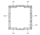
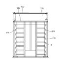
- FIG. 1 It is a top view which shows the magnetic decomposition apparatus which concerns on embodiment of this invention. It is a cross-sectional top view of the thermal decomposition process chamber of the magnetic decomposition apparatus shown in FIG. It is the side view seen from the A1 and A2 direction in FIG. It is the sectional side view seen from the A1 and A2 direction in FIG. It is a sectional side view of the thermal decomposition process chamber of the magnetic decomposition apparatus shown in FIG. It is the expansion
- the magnetic decomposing apparatus 10 includes a decomposition processing unit 100 and a filter unit 200. Both are connected by the exhaust duct 20 and the intake duct 30, and the smoke is circulated between the decomposition processing unit 100 and the filter unit 200.
- a hopper 120 for introducing waste is provided at the top of the thermal decomposition processing chamber 110 where the waste is decomposed.
- Various items such as household waste, waste paper, cardboard, waste plastic, wood waste, vegetable waste, rubber, vinyl, etc. can be targeted as the hopper 120.
- the upper shutter 122 is provided on the upper part of the hopper 120, and the lower shutter 124 is provided on the lower part. Further, a staircase 130 for transporting waste from the ground to the hopper 120 and a step (floor) 132 for loading are provided.
- the upper shutter 122 is opened with the lower shutter 124 closed, and waste is thrown into the hopper 120.
- the lower shutter 124 is opened with the upper shutter 122 closed, and the waste is disposed in the pyrolysis chamber 110. It is possible to satisfactorily prevent the outside air (air that has not been magnetically decomposed) from flowing into the thermal decomposition treatment chamber 110 by dropping it into the air.
- the hopper 120 is connected to the exhaust duct 20, and the exhaust gas filling the hopper 120 can be exhausted to the filter unit 200 by the above-described opening and closing operation, so that the exhaust gas can be prevented from flowing out to the outside.
- the upper shutter 122 and the lower shutter 124 may be electrically operated, hydraulic, or the like as necessary, or may be opened and closed in conjunction with each other.
- the upper shutter 122 operates a switch (not shown) to rotationally drive the ball screw 122E via the geared motor 122A, the sprocket 122B, the roller chain 122C, and the sprocket 122D, and the rotational motion is shuttered by the driving screw 122F.
- the drive rod 122G is converted into a linear motion and driven to open and close.
- the lower shutter 124 rotates a ball screw 124E via a geared motor 124A, a sprocket 124B, a roller chain 124C, and a sprocket 124D by operating a switch (not shown). It is driven to open and close by converting into a linear motion. Since the lower shutter 124 is a pair of left and right shutter plates, it is driven by a right and left target drive mechanism.
- the thermal decomposition chamber 110 is provided with an opening 112 on its side surface and is closed during the decomposition process.
- the opening 112 is used to send hot air into the processing chamber at the start of the decomposition process and to remove residues after the decomposition process.
- the inner wall of the thermal decomposition treatment chamber 110 mainly serves as a flue, and is formed using a material such as an iron plate that is a ferromagnetic material. Further, as shown in FIGS. 4 and 5, a swash plate flue 114 having an air suction portion facing upward is formed on the inner wall of the pyrolysis chamber 110. Regardless of the position of the waste thrown into the chamber 110, the flue gas generated by the thermal decomposition of the waste is guided upward by the swash plate flue 114 and efficiently discharged into the exhaust duct 20. It will be.
- the filter unit 200 includes a plurality of filter devices and a blower device for circulating the exhaust gas.
- Smoke introduced from the exhaust duct 20 described above passes through the filter unit 200 in the order of the shower 210, the swash plate filter 220, the blower 230, the water tank filter 240, the cloth filter 250, the zeolite filter 260, and the activated carbon filter 270, and takes in the intake air. It reaches the duct 30. Further, the blower 230 circulates smoke in the entire apparatus.
- the shower 210 is configured to apply a shower to the flue gas from the water spray pipe 212.
- the swash plate filter 220 is configured to emit smoke to a plurality of diagonally arranged plates 222.
- the shower 210 and the swash plate filter 220 are for reducing the temperature of the flue gas, removing tar, and reducing the burden on the subsequent blower 230.
- the aquarium filter 240 is mainly for removing tar by the smoke exhausted as bubbles in the water.
- the cloth filter 250 is for removing moisture in the flue gas by the cloth.
- the zeolite filter 260 mainly has a smoke eliminating effect and removes the color.
- the activated carbon filter 270 is mainly for removing odors in the flue gas.
- the flue gas from which tars and odors have been removed by these filters does not pose any problem even if it is released into the atmosphere, but in this embodiment, the flue gas passes through the intake duct 30 and passes through the iron pipe and is thermally decomposed. Return to the processing chamber 110. At this time, the flue gas is magnetically decomposed by the strong magnetic field generated by the magnet 32 provided in the intake duct 30. The magnet 32 is attached to the outside of the iron pipe protruding outside the pyrolysis chamber 110.
- a permanent magnet such as an Nd—Fe—B magnet (neodymium magnet) or an Sm—Co magnet (samarium-cobalt magnet) is a suitable example.
- a strong magnetic field can be obtained without the need for another energy source.
- oxygen and nitrogen in the air are separated.
- the magnetic susceptibility of oxygen is 1000 times that of nitrogen, this acts on waste and undergoes thermal decomposition.
- a permanent magnet having a magnetic flux density of, for example, about 700 mT (7000 gauss) or higher is used as the magnet 32.
- the hot air gun 40 is used to start processing. Thereby, the decomposition process is started and continued without using any fire. Specifically, the opening 112 of the thermal decomposition treatment chamber 110 is opened, hot air is blown from here with the hot air gun 40, and the blower 230 is driven to magnetically decompose and circulate the smoke to continue the decomposition process. It is supposed to be done.
- the upper shutter 122 is opened with the lower shutter 124 closed, and waste is thrown into the hopper 120.
- the lower shutter 124 is opened with the upper shutter 122 closed, and the waste falls into the pyrolysis chamber 110.
- the blower 230 is driven to circulate air between the decomposition processing unit 100 and the filter unit 200 through the exhaust duct 20 and the intake duct 30. Thereby, the air is magnetically decomposed by the magnetic field of the magnet 32 provided in the intake duct 30, and the decomposed air is sent to the thermal decomposition treatment chamber 110.
- the intake / exhaust of the decomposition processing unit 110 exhausts the flue gas expanded by the thermal decomposition through the exhaust duct 20, but only the required amount is sent in by the bypass pipe 50 without forcibly sending in the intake air.
- the bypass pipe 50 by providing the bypass pipe 50, the gas in the intake duct 30 can be sucked into the pyrolysis chamber 110 by a necessary amount and the unnecessary amount can be diverted to the exhaust duct 20 via the bypass pipe 50.
- the opening 112 of the pyrolysis chamber 110 is opened, and hot air of about 500 ° C. is blown by the hot air gun 40, for example. Then, the waste is thermally decomposed in the thermal decomposition treatment chamber 110. Air blowing by the hot air gun 40 may be performed for about 3 minutes, and then thermal decomposition continues.
- the temperature in the pyrolysis chamber 110 is approximately 400 to 500 ° C., and no internal combustion occurs.
- Smoke generated by the thermal decomposition is sent to the filter unit 200 through the exhaust duct 20.
- the flue gas passes through the shower 210 and the swash plate filter 220 of the filter unit 200, so that the temperature decreases, tar is removed, and the exhaust gas passes through the blower 230.
- the flue gas further passes through the water tank filter 240 to further remove tar, and then the cloth filter 250 removes moisture.
- the flue gas is sent from the intake duct 30 to the thermal decomposition treatment chamber 110. At this time, a magnetic field of smoke is applied by the magnet 32 and used for the thermal decomposition process.
- the water tank of the shower 210 separates the water tank of the shower 210 and the water tank filter 240, and mix the surfactant in the water tank of the shower 210 in the range of 1% to 5%. Further, sodium hydroxide is mixed in the water tank of the water tank filter 240 in the range of 1% to 5% to adsorb carbon dioxide in the flue gas. As a result, the gas that passes through the intake duct 30 and returns to the thermal decomposition treatment chamber 110 is made cleaner.
- the present embodiment has the following effects. a. Smoke generated in the decomposition processing unit 100 is sent from the exhaust duct 20 to the filter unit 200, and after the tar removal and deodorization processing by the filter unit 200, the decomposition process is performed while applying the magnetic field by the magnet 32 provided in the intake duct 30. Since it was made to return and circulate to the part 100, a magnetic decomposition process can be performed using a flue gas effectively. b. Since the filter unit 200 is separated from the decomposition processing unit 100, if a plurality of filter units 200 are prepared and the connection between the exhaust duct 20 and the intake duct 30 is switched, the used filter unit 200 can be changed.
- this invention is not limited to embodiment mentioned above, A various change can be added in the range which does not deviate from the summary of this invention. For example, the following are also included.
- (1) The shapes and dimensions shown in the above embodiment are merely examples, and the design can be changed so as to achieve the same actions and effects.
- the shower 210 and the swash plate filter 220 are provided in the front stage (intake side) of the blower 230, and the water tank filter 240, the cloth filter 250, the zeolite filter 260, and the activated carbon filter 270 are provided in the rear stage of the blower 230 ( Although provided on the exhaust side), which filter is provided at which position may be appropriately set as necessary.
- the filter unit is separated from the decomposition processing unit, and the magnetic field is applied between them to circulate the smoke, which is suitable for the decomposition processing of various wastes.
Landscapes
- Engineering & Computer Science (AREA)
- Chemical & Material Sciences (AREA)
- Health & Medical Sciences (AREA)
- Mechanical Engineering (AREA)
- General Engineering & Computer Science (AREA)
- Chemical Kinetics & Catalysis (AREA)
- Environmental & Geological Engineering (AREA)
- Oil, Petroleum & Natural Gas (AREA)
- Analytical Chemistry (AREA)
- General Chemical & Material Sciences (AREA)
- General Health & Medical Sciences (AREA)
- Biomedical Technology (AREA)
- Epidemiology (AREA)
- Life Sciences & Earth Sciences (AREA)
- Animal Behavior & Ethology (AREA)
- Public Health (AREA)
- Veterinary Medicine (AREA)
- Combustion & Propulsion (AREA)
- Organic Chemistry (AREA)
- Toxicology (AREA)
- Processing Of Solid Wastes (AREA)
- Treating Waste Gases (AREA)
- Physical Or Chemical Processes And Apparatus (AREA)
- Filtering Of Dispersed Particles In Gases (AREA)
Priority Applications (5)
| Application Number | Priority Date | Filing Date | Title |
|---|---|---|---|
| KR1020177024867A KR20170110701A (ko) | 2015-02-06 | 2016-02-04 | 자기 분해 장치 및 자기 분해 방법 |
| CN201680008737.5A CN107206440A (zh) | 2015-02-06 | 2016-02-04 | 磁分解装置及磁分解方法 |
| MYPI2017702847A MY182480A (en) | 2015-02-06 | 2016-02-04 | Magnetic decomposition device |
| US15/549,105 US20180021721A1 (en) | 2015-02-06 | 2016-02-04 | Magnetic decomposition device, and magnetic decomposition method |
| PH12017501405A PH12017501405A1 (en) | 2015-02-06 | 2017-08-04 | Magnetic decomposition device, and magnetic decomposition method. |
Applications Claiming Priority (2)
| Application Number | Priority Date | Filing Date | Title |
|---|---|---|---|
| JP2015022411A JP6186560B2 (ja) | 2015-02-06 | 2015-02-06 | 磁気分解装置 |
| JP2015-022411 | 2015-02-06 |
Publications (1)
| Publication Number | Publication Date |
|---|---|
| WO2016125858A1 true WO2016125858A1 (ja) | 2016-08-11 |
Family
ID=56564197
Family Applications (1)
| Application Number | Title | Priority Date | Filing Date |
|---|---|---|---|
| PCT/JP2016/053362 Ceased WO2016125858A1 (ja) | 2015-02-06 | 2016-02-04 | 磁気分解装置、及び磁気分解方法 |
Country Status (7)
| Country | Link |
|---|---|
| US (1) | US20180021721A1 (https=) |
| JP (1) | JP6186560B2 (https=) |
| KR (1) | KR20170110701A (https=) |
| CN (1) | CN107206440A (https=) |
| MY (1) | MY182480A (https=) |
| PH (1) | PH12017501405A1 (https=) |
| WO (1) | WO2016125858A1 (https=) |
Families Citing this family (3)
| Publication number | Priority date | Publication date | Assignee | Title |
|---|---|---|---|---|
| AU2018267615B1 (en) * | 2018-11-20 | 2019-05-02 | Serendipity Technologies Llc | Improvement to furnace apparatus |
| CN112107948B (zh) * | 2020-10-13 | 2021-07-23 | 中国城市建设研究院有限公司 | 生活垃圾焚烧烟气的湿法处理设备 |
| KR102492094B1 (ko) * | 2021-10-06 | 2023-01-27 | 김종엽 | 자기 열분해 장치 |
Citations (5)
| Publication number | Priority date | Publication date | Assignee | Title |
|---|---|---|---|---|
| JP2006214712A (ja) * | 2005-01-07 | 2006-08-17 | Mitsubishi Heavy Ind Ltd | 加圧高温ガス冷却器 |
| JP2010058103A (ja) * | 2008-09-01 | 2010-03-18 | Eco Clean Eiko:Kk | 磁気空気作用による有機物熱分解装置 |
| JP2010075823A (ja) * | 2008-09-25 | 2010-04-08 | Jiro Terasawa | 有機物分解処理装置 |
| JP2011005457A (ja) * | 2009-06-29 | 2011-01-13 | Akira Uzawa | 有機物分解処理装置 |
| JP2014128781A (ja) * | 2012-12-27 | 2014-07-10 | Sekiji Aoki | 磁場空気流による不用有機物熱分解継続装置 |
Family Cites Families (4)
| Publication number | Priority date | Publication date | Assignee | Title |
|---|---|---|---|---|
| US7803216B2 (en) * | 2005-12-28 | 2010-09-28 | Mitsubishi Heavy Industries, Ltd. | Pressurized high-temperature gas cooler |
| CN101307154B (zh) * | 2007-05-15 | 2011-06-22 | 蔡松桦 | 复合式物质热裂解整合系统 |
| CN201092568Y (zh) * | 2007-07-18 | 2008-07-30 | 焦雪珂 | 裂解炉 |
| US20090234173A1 (en) * | 2008-03-17 | 2009-09-17 | Myeong Yurl Lee | Organic waste decomposition system and method with blower |
-
2015
- 2015-02-06 JP JP2015022411A patent/JP6186560B2/ja active Active
-
2016
- 2016-02-04 KR KR1020177024867A patent/KR20170110701A/ko not_active Ceased
- 2016-02-04 US US15/549,105 patent/US20180021721A1/en not_active Abandoned
- 2016-02-04 WO PCT/JP2016/053362 patent/WO2016125858A1/ja not_active Ceased
- 2016-02-04 MY MYPI2017702847A patent/MY182480A/en unknown
- 2016-02-04 CN CN201680008737.5A patent/CN107206440A/zh active Pending
-
2017
- 2017-08-04 PH PH12017501405A patent/PH12017501405A1/en unknown
Patent Citations (5)
| Publication number | Priority date | Publication date | Assignee | Title |
|---|---|---|---|---|
| JP2006214712A (ja) * | 2005-01-07 | 2006-08-17 | Mitsubishi Heavy Ind Ltd | 加圧高温ガス冷却器 |
| JP2010058103A (ja) * | 2008-09-01 | 2010-03-18 | Eco Clean Eiko:Kk | 磁気空気作用による有機物熱分解装置 |
| JP2010075823A (ja) * | 2008-09-25 | 2010-04-08 | Jiro Terasawa | 有機物分解処理装置 |
| JP2011005457A (ja) * | 2009-06-29 | 2011-01-13 | Akira Uzawa | 有機物分解処理装置 |
| JP2014128781A (ja) * | 2012-12-27 | 2014-07-10 | Sekiji Aoki | 磁場空気流による不用有機物熱分解継続装置 |
Also Published As
| Publication number | Publication date |
|---|---|
| JP6186560B2 (ja) | 2017-08-30 |
| CN107206440A (zh) | 2017-09-26 |
| KR20170110701A (ko) | 2017-10-11 |
| US20180021721A1 (en) | 2018-01-25 |
| JP2016144776A (ja) | 2016-08-12 |
| PH12017501405A1 (en) | 2018-01-29 |
| MY182480A (en) | 2021-01-25 |
Similar Documents
| Publication | Publication Date | Title |
|---|---|---|
| JP6333478B2 (ja) | 炉装置 | |
| WO2016125858A1 (ja) | 磁気分解装置、及び磁気分解方法 | |
| JP6841631B2 (ja) | 紫外線照射装置 | |
| JP7176720B2 (ja) | 熱分解装置 | |
| KR102772862B1 (ko) | 가축 및 반려동물 사체 처리 차량 | |
| JP2018108571A (ja) | 有機物類の低温熱分解処理装置 | |
| JP2011005457A (ja) | 有機物分解処理装置 | |
| JP2010155231A6 (ja) | 処理物の低温分解処理方法及び装置 | |
| JP2010155231A (ja) | 処理物の低温分解処理方法及び装置 | |
| KR100861002B1 (ko) | 음식물 쓰레기 처리기 및 그의 처리방법 | |
| KR101532945B1 (ko) | 악취 및 먼지와 유해가스 제거기능을 갖춘 마이크로파 방식의 동물사체 처리장치 | |
| JP6223720B2 (ja) | 磁場熱分解炉 | |
| WO2018123565A1 (ja) | 有機物類の低温熱分解処理装置 | |
| CN101213404A (zh) | 用于废物处理的真空焚烧设备及其真空保持方法 | |
| KR100343786B1 (ko) | 가정용 음식물 쓰레기 소멸식 처리장치 | |
| KR101381245B1 (ko) | 동물 사체 처리장치 | |
| KR101968679B1 (ko) | 음식물처리기용 탈취장치 | |
| KR20090030394A (ko) | 업소용 음식물 쓰레기 처리장치. | |
| KR20090030395A (ko) | 가정용 음식물 쓰레기 처리장치. | |
| JPH0679130A (ja) | 集塵機を用いた気体中の臭気物質、刺激物質又は粘性物質の除去方法 | |
| FR3109532A1 (fr) | Armoire de décontamination par l'ozone, en particulier pour la dégradation des HAP et/ou la destruction de micro-organismes | |
| KR102537371B1 (ko) | 열 효율성을 향상시킨 음식물쓰레기 처리기의 탈취장치 | |
| JP3734920B2 (ja) | 消滅型生ゴミ処理機 | |
| JP2004359875A (ja) | 医療関係廃棄物を固形燃料化する方法及びそのプラント | |
| KR100652907B1 (ko) | 음식물쓰레기처리기의 악취배기장치 |
Legal Events
| Date | Code | Title | Description |
|---|---|---|---|
| 121 | Ep: the epo has been informed by wipo that ep was designated in this application |
Ref document number: 16746689 Country of ref document: EP Kind code of ref document: A1 |
|
| DPE1 | Request for preliminary examination filed after expiration of 19th month from priority date (pct application filed from 20040101) | ||
| WWE | Wipo information: entry into national phase |
Ref document number: 15549105 Country of ref document: US Ref document number: 12017501405 Country of ref document: PH |
|
| NENP | Non-entry into the national phase |
Ref country code: DE |
|
| ENP | Entry into the national phase |
Ref document number: 20177024867 Country of ref document: KR Kind code of ref document: A |
|
| 122 | Ep: pct application non-entry in european phase |
Ref document number: 16746689 Country of ref document: EP Kind code of ref document: A1 |