WO2016125607A1 - 流体圧機器の接続装置 - Google Patents
流体圧機器の接続装置 Download PDFInfo
- Publication number
- WO2016125607A1 WO2016125607A1 PCT/JP2016/051827 JP2016051827W WO2016125607A1 WO 2016125607 A1 WO2016125607 A1 WO 2016125607A1 JP 2016051827 W JP2016051827 W JP 2016051827W WO 2016125607 A1 WO2016125607 A1 WO 2016125607A1
- Authority
- WO
- WIPO (PCT)
- Prior art keywords
- fluid pressure
- nut
- cap
- hole
- holder
- Prior art date
- Legal status (The legal status is an assumption and is not a legal conclusion. Google has not performed a legal analysis and makes no representation as to the accuracy of the status listed.)
- Ceased
Links
Images


Classifications
-
- F—MECHANICAL ENGINEERING; LIGHTING; HEATING; WEAPONS; BLASTING
- F15—FLUID-PRESSURE ACTUATORS; HYDRAULICS OR PNEUMATICS IN GENERAL
- F15B—SYSTEMS ACTING BY MEANS OF FLUIDS IN GENERAL; FLUID-PRESSURE ACTUATORS, e.g. SERVOMOTORS; DETAILS OF FLUID-PRESSURE SYSTEMS, NOT OTHERWISE PROVIDED FOR
- F15B21/00—Common features of fluid actuator systems; Fluid-pressure actuator systems or details thereof, not covered by any other group of this subclass
- F15B21/003—Systems with different interchangeable components, e.g. using preassembled kits
-
- F—MECHANICAL ENGINEERING; LIGHTING; HEATING; WEAPONS; BLASTING
- F16—ENGINEERING ELEMENTS AND UNITS; GENERAL MEASURES FOR PRODUCING AND MAINTAINING EFFECTIVE FUNCTIONING OF MACHINES OR INSTALLATIONS; THERMAL INSULATION IN GENERAL
- F16B—DEVICES FOR FASTENING OR SECURING CONSTRUCTIONAL ELEMENTS OR MACHINE PARTS TOGETHER, e.g. NAILS, BOLTS, CIRCLIPS, CLAMPS, CLIPS OR WEDGES; JOINTS OR JOINTING
- F16B7/00—Connections of rods or tubes, e.g. of non-circular section, mutually, including resilient connections
- F16B7/04—Clamping or clipping connections
-
- F—MECHANICAL ENGINEERING; LIGHTING; HEATING; WEAPONS; BLASTING
- F16—ENGINEERING ELEMENTS AND UNITS; GENERAL MEASURES FOR PRODUCING AND MAINTAINING EFFECTIVE FUNCTIONING OF MACHINES OR INSTALLATIONS; THERMAL INSULATION IN GENERAL
- F16B—DEVICES FOR FASTENING OR SECURING CONSTRUCTIONAL ELEMENTS OR MACHINE PARTS TOGETHER, e.g. NAILS, BOLTS, CIRCLIPS, CLAMPS, CLIPS OR WEDGES; JOINTS OR JOINTING
- F16B2/00—Friction-grip releasable fastenings
- F16B2/02—Clamps, i.e. with gripping action effected by positive means other than the inherent resistance to deformation of the material of the fastening
- F16B2/14—Clamps, i.e. with gripping action effected by positive means other than the inherent resistance to deformation of the material of the fastening using wedges
-
- F—MECHANICAL ENGINEERING; LIGHTING; HEATING; WEAPONS; BLASTING
- F16—ENGINEERING ELEMENTS AND UNITS; GENERAL MEASURES FOR PRODUCING AND MAINTAINING EFFECTIVE FUNCTIONING OF MACHINES OR INSTALLATIONS; THERMAL INSULATION IN GENERAL
- F16B—DEVICES FOR FASTENING OR SECURING CONSTRUCTIONAL ELEMENTS OR MACHINE PARTS TOGETHER, e.g. NAILS, BOLTS, CIRCLIPS, CLAMPS, CLIPS OR WEDGES; JOINTS OR JOINTING
- F16B7/00—Connections of rods or tubes, e.g. of non-circular section, mutually, including resilient connections
- F16B7/04—Clamping or clipping connections
- F16B7/044—Clamping or clipping connections for rods or tubes being in angled relationship
- F16B7/0446—Clamping or clipping connections for rods or tubes being in angled relationship for tubes using the innerside thereof
- F16B7/0453—Clamping or clipping connections for rods or tubes being in angled relationship for tubes using the innerside thereof the tubes being drawn towards each other
- F16B7/0466—Clamping or clipping connections for rods or tubes being in angled relationship for tubes using the innerside thereof the tubes being drawn towards each other by a screw-threaded stud with a conical tip acting on an inclined surface
-
- F—MECHANICAL ENGINEERING; LIGHTING; HEATING; WEAPONS; BLASTING
- F16—ENGINEERING ELEMENTS AND UNITS; GENERAL MEASURES FOR PRODUCING AND MAINTAINING EFFECTIVE FUNCTIONING OF MACHINES OR INSTALLATIONS; THERMAL INSULATION IN GENERAL
- F16L—PIPES; JOINTS OR FITTINGS FOR PIPES; SUPPORTS FOR PIPES, CABLES OR PROTECTIVE TUBING; MEANS FOR THERMAL INSULATION IN GENERAL
- F16L41/00—Branching pipes; Joining pipes to walls
- F16L41/08—Joining pipes to walls or pipes, the joined pipe axis being perpendicular to the plane of a wall or to the axis of another pipe
- F16L41/086—Joining pipes to walls or pipes, the joined pipe axis being perpendicular to the plane of a wall or to the axis of another pipe fixed with screws
-
- F—MECHANICAL ENGINEERING; LIGHTING; HEATING; WEAPONS; BLASTING
- F16—ENGINEERING ELEMENTS AND UNITS; GENERAL MEASURES FOR PRODUCING AND MAINTAINING EFFECTIVE FUNCTIONING OF MACHINES OR INSTALLATIONS; THERMAL INSULATION IN GENERAL
- F16N—LUBRICATING
- F16N7/00—Arrangements for supplying oil or unspecified lubricant from a stationary reservoir or the equivalent in or on the machine or member to be lubricated
- F16N7/30—Arrangements for supplying oil or unspecified lubricant from a stationary reservoir or the equivalent in or on the machine or member to be lubricated the oil being fed or carried along by another fluid
- F16N7/32—Mist lubrication
- F16N7/34—Atomising devices for oil
-
- F—MECHANICAL ENGINEERING; LIGHTING; HEATING; WEAPONS; BLASTING
- F16—ENGINEERING ELEMENTS AND UNITS; GENERAL MEASURES FOR PRODUCING AND MAINTAINING EFFECTIVE FUNCTIONING OF MACHINES OR INSTALLATIONS; THERMAL INSULATION IN GENERAL
- F16N—LUBRICATING
- F16N25/00—Distributing equipment with or without proportioning devices
-
- F—MECHANICAL ENGINEERING; LIGHTING; HEATING; WEAPONS; BLASTING
- F16—ENGINEERING ELEMENTS AND UNITS; GENERAL MEASURES FOR PRODUCING AND MAINTAINING EFFECTIVE FUNCTIONING OF MACHINES OR INSTALLATIONS; THERMAL INSULATION IN GENERAL
- F16N—LUBRICATING
- F16N39/00—Arrangements for conditioning of lubricants in the lubricating system
- F16N39/06—Arrangements for conditioning of lubricants in the lubricating system by filtration
Definitions
- the present invention relates to a fluid pressure device capable of communicating fluid passages between a plurality of fluid pressure devices by connecting, in parallel, a plurality of fluid pressure devices of the same type or different types such as filters, regulators, and lubricators in parallel. It relates to the connection device.
- connection device that integrally connects fluid pressure devices such as filters, regulators, and lubricators used in pneumatic circuits (see Japanese Patent No. 3851119).
- a through-hole is formed in a body having a hole, an engagement member is engaged with a bolt inserted through the through-hole, and an engagement flange of the engagement member is connected to two adjacent fluids.
- a structure is adopted in which the fluid pressure devices are connected to each other through the engagement flange by fastening the bolts after being engaged with protrusions provided in the vicinity of the ports of the pressure devices.
- connection structure of fluid pressure equipment that is further simplified in configuration and suitable for downsizing in connection with the connection device (see Japanese Patent No. 5565634).
- the present invention has been made in connection with the above proposal, and can easily and quickly connect fluid pressure devices such as filters, regulators, and lubricators, thereby further improving the assembly workability. It is an object of the present invention to provide a connecting device for a fluid pressure device that is possible.
- the present invention is arranged between one and the other fluid pressure devices and integrally connects the fluid pressure devices to each fluid of the one and the other fluid pressure devices.
- a fluid pressure device connection device for communicating passages with each other A base member provided with a hole that allows one fluid passage and the other fluid passage to communicate with each other; A set provided with a pair of holding portions that are provided on one side surface and the other side surface of the base member that are orthogonal to the axial direction of the hole, and that engage with protrusions provided on one and the other fluid pressure devices, respectively.
- a holder of A set of fastening members provided on one side and the other side of the base member and capable of fixing the holder;
- the fastening member has a main body portion that has a substantially rectangular cross section and engages with the base member, and a screw portion that protrudes from the main body portion and is inserted into the holder. On one side, the screw part is inserted, the nut is screwed together, and a cap is fitted.
- the holder and the nut are previously fitted and integrated with the cap, and then fixed to the screw portion of the fastening member. Therefore, the assembling work of these parts becomes easy, and the effect of improving the working efficiency of the assembling process can be obtained.
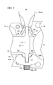
- FIG. 1 is an external perspective view of a fluid pressure unit to which a fluid pressure device connecting device according to an embodiment of the present invention is applied.
- FIG. 2 is a front view of the fluid pressure unit shown in FIG. 3 is an overall cross-sectional view of a filter constituting the fluid pressure unit of FIG.
- FIG. 4 is an overall cross-sectional view of the lubricator constituting the fluid pressure unit of FIG.
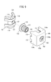
- FIG. 5 is an external perspective view of the connection device shown in FIG. 6 is an exploded perspective view of the connection device of FIG.
- FIG. 7 is a plan view of a main part in a state where the filter and the regulator are connected using the connection device shown in FIG. FIG.
- FIG. 8 is a main part longitudinal cross-sectional view showing a combined state of a fastening member, a holder, a nut, and a cap constituting the connecting device shown in FIG.
- FIG. 9 is an exploded perspective view of a modification of the connection device shown in FIG.
- FIG. 10 is a longitudinal sectional view of an essential part of a modification of the connection device of FIG.
- reference numeral 10 indicates a fluid pressure unit 10 to which connection devices 18a and 18b of a fluid pressure device according to an embodiment of the present invention are applied. Since the connecting devices 18a and 18b are composed of the same constituent elements, one connecting device 18a will be described below, the other connecting device 18b will be given the same reference numeral, and detailed description thereof will be omitted. To do.
- the fluid pressure unit 10 includes a filter 12 that removes dust and the like contained in the pressure fluid, a regulator 14 that reduces the pressure of the pressure fluid, and the pressure fluid. And a set of connecting devices 18a and 18b disposed between the filter 12, the regulator 14 and the lubricator 16, and connecting the filter 12, the regulator 14 and the lubricator 16 to each other. Composed.
- the filter 12, the regulator 14, and the lubricator 16 described above function as a fluid pressure device that supplies a pressure fluid to the fluid passage inside thereof, and the regulator 14 is disposed between the filter 12 and the lubricator 16.
- the filter 12 includes a first body 20, a case unit 22 connected to a lower portion of the first body 20, and a filter unit 24 housed in the case unit 22. Including.
- the first body 20 is provided with first and second ports 26 and 28 through which pressure fluid is supplied and discharged.
- the first port 26 is connected to a pipe (not shown), and the pressure fluid is passed through the pipe. Is supplied.
- the pressure fluid supplied to the first port 26 is discharged to the regulator 14 described later.
- a pair of engaging protrusions 30 a and 30 b formed to face each other on the outer edge portions of the end surfaces provided with the first and second ports 26 and 28 are provided.
- the case unit 22 includes an outer case 32 formed in a bottomed cylindrical shape, an inner case 34 inserted into the outer case 32, a release button 36 provided to be displaceable with respect to the outer case 32, And a drain cock 38 provided at the bottom of the outer case 32 and the inner case 34.
- the upper end portion of the release button 36 is inserted into a recess (not shown) formed in the attachment hole 40 of the first body 20. Is done. Thereby, the displacement to the rotation direction of the case unit 22 with respect to the 1st body 20 is controlled.
- the regulator 14 adjusts the pressure fluid by operating the second body 42, a handle 44 that is rotatably provided at the lower portion of the second body 42, and the handle 44.
- a pressure adjusting mechanism (not shown) capable of pressing.
- a pair of ports (not shown) through which pressure fluid is supplied and discharged are formed on the sides of the second body 42, and one port is connected to and communicates with the second port 28 of the filter 12. The pressure fluid is supplied from the filter 12, the other port is connected to and communicates with a third port 56 (described later) of the lubricator 16, and the pressure fluid is discharged.
- a pair of engaging protrusions 46a and 46b are provided so as to face each other on the outer edge of the end face provided with a pair of ports.
- the regulator 14 includes a pressure adjustment mechanism therein, and rotates the handle 44 to drive the pressure adjustment mechanism, thereby adjusting the pressure of the pressure fluid supplied from one port to a desired pressure. Thereafter, the liquid is discharged from the other port and supplied to the lubricator 16.
- Lubricator 16 is used for the purpose of supplying lubricating oil to a sliding part or the like in another fluid pressure device by dropping lubricating oil into the pressure fluid and using the flow of the pressure fluid. As shown in FIGS. 1, 2, and 4, the lubricator 16 is inserted into the third body 48, a case unit 50 connected to a lower portion of the third body 48, and the third body 48. And a holder 54 for fixing the dropping part 52 to the third body 48.
- the third body 48 is provided with third and fourth ports 56 and 58 through which pressure fluid is supplied and discharged laterally, and the third port 56 and the fourth port 58 are connected via a communication path (not shown). Communicate with each other.
- the 3rd port 56 is connected with the other port in the regulator 14 provided adjacently, and the 4th port 58 is connected with piping which is not shown in figure.
- a pair of engaging protrusions 60a and 60b (see FIG. 2) formed on the side surface of the third body 48 so as to face each other on the outer edge portions of the end surfaces provided with the third and fourth ports 56 and 58. Reference) is provided.
- the case unit 50 includes an outer case 62 formed in a bottomed cylindrical shape, an inner case 64 inserted into the outer case 62, and a release button 66 provided to be displaceable with respect to the outer case 62. Including.
- the inner case 64 is filled with lubricating oil through an oil supply plug 68 provided in the third body 48.
- the case unit 50 is attached to the attachment hole 69 of the third body 48.
- the dripping portion 52 includes an inner member 70 that is inserted into the third body 48, and a dripping plug 72 that is provided on the inner member 70.
- the storage chamber 74 communicates with an oil passage 76 extending downward, and lubricating oil is supplied through the oil passage 76, and a dripping port 78 is opened downward at a substantially central portion thereof.
- the oil passage 76 communicates with an oil supply port 82 formed in the holder 54.
- the holder 54 is attached to the lower part of the inner member 70 constituting the dropping part 52, and is provided with an oil supply port 82 that is held by holding a part of the damper 80 and communicates with the oil passage 76.
- the oil supply port 82 protrudes downward (in the direction of arrow B) and is disposed inside the inner case 64 and is connected to the oil guide tube 84.
- the lubricating oil filled in the inner case 64 flows to the holder 54 side through the oil guide tube 84, the lubricating oil is supplied to the storage chamber 74 through the oil passage 76, and is communicated from the storage chamber 74 through the dropping port 78. It is dripped in. Thereby, a desired amount of lubricating oil is mixed with the pressure fluid flowing through the communication path.
- the connecting device 18a (18b) includes a base member (body) 86 formed in a substantially square and thin plate shape, and one side surface of the base member 86. And a pair of first and second fastening members 88, 90 provided on the other side surface, and a pair of first and second holders held by the first and second fastening members 88, 90 to hold the fluid pressure devices. 92 and 94, and a mounting member 96 connected to the other side of the base member 86.
- the base member 86 is formed with a substantially constant thickness, and a hole 98 is formed at a substantially central portion thereof.
- a seal ring 100 made of an elastic material is attached to the hole 98.
- the seal ring 100 is provided such that its outer peripheral surface comes into contact with the inner peripheral surface of the hole 98.
- first and second recesses 102, 104 are provided on one side surface and the other side surface of the base member 86, which are recessed toward the hole 98 side and in which first and second holders 92, 94 described later are respectively mounted.
- a groove 106 provided on the hole 98 side with respect to the first and second recesses 102 and 104, and a communication hole 108 for communicating the groove 106 with the first and second recesses 102 and 104, respectively. And are formed.
- the groove 106 is a space opened in a rectangular cross section, is formed substantially parallel to the first and second recesses 102, 104, and a communication hole 108 is formed at a substantially center along the longitudinal direction of the groove 106.
- a pair of flange portions 110 that are widened in the thickness direction of the base member 86 are respectively formed on the upper surface and the lower surface of the base member 86.
- the upper surface and the lower surface side of the base member 86 are formed wide.
- the first and second fastening members 88 and 90 include a main body portion 112 having a substantially rectangular cross section and a screw portion (shaft portion) 114 provided at the center in the longitudinal direction of the main body portion 112.
- the portion 114 is formed to be orthogonal to the main body portion 112 and protrude by a predetermined length.
- first and second fastening members 88 and 90 are formed from the main body portion 112 and the screw portion 114 in a substantially T-shaped cross section.
- the threaded portion 114 protrudes from the approximate center of the relatively thick main body portion 112 so as to be orthogonal to the longitudinal direction.
- the threaded portion 114 is, for example, a stud bolt in which a male screw is engraved on the outer peripheral surface thereof. It is.
- the main body portion 112 is inserted into the groove portion 106 formed on one side surface of the base member 86, and the screw portion 114 is inserted into the communication hole 108.
- the tip of the screw part 114 protrudes into the first recess 102.
- the second fastening member 90 has a body portion 112 inserted into a groove portion 106 formed on the other side surface of the base member 86, and a screw portion 114 inserted into the communication hole 108, respectively. 2 protrudes into the recess 104.
- first and second fastening members 88 and 90 are formed with the same thickness as the thickness of the base member 86, the first and second fastening members 88 and 90 are mounted. Thus, the base member 86 does not protrude in the thickness direction.
- the first and second holders 92 and 94 are formed in a flat portion 116 formed substantially at the center portion and first and second portions formed at both ends of the flat portion 116 and inclined by a predetermined angle so as to approach each other. Holding portions 118 and 120 are provided.
- the first and second holders 92 and 94 are provided with ribs 119 and 121 that are bent from the first holding part 118 to the second holding part 120.
- the flat portion 116 is inserted into the first and second recesses 102 and 104 of the base member 86, and the first and second holding portions 118 and 120 are respectively connected to the protrusions 30b for engagement of the filter 12 and the regulator 14, It is arranged on the 46a side and contacts.
- a bolt hole 122 into which the threaded portion 114 of the first and second fastening members 88 and 90 is loosely fitted is formed in the approximate center of the flat portion 116.
- the first holder (retainer) 92 is held against the screw portion 114 by screwing the first nut 126 in a state where the screw portion 114 of the first fastening member 88 is inserted into the bolt hole 122.
- the second holder 94 is held with respect to the threaded portion 114 by screwing the second nut 128 in a state where the threaded portion 114 of the second fastening member 90 is inserted.
- the outer periphery of the cylindrical head portion 127 of the first nut 126 is provided with an uneven portion along the axial direction, and the inner peripheral surface thereof is provided with a screw hole 130 into which a wrench (not shown) is inserted.
- Reference numeral 132 denotes a flange portion integral with the head portion 127.
- a retainer cap (hereinafter referred to as a cap) 150 is fitted so as to surround a part of the first holder 92 and the first nut 126. 6 and 8, the cap 150 has a curved surface portion 152 formed of a smooth surface, and first and second side wall portions 154a and 154b provided at both ends of the curved surface portion 152.
- the curved surface portion 152 includes a first flat surface portion 156a and a second flat surface portion 156b that are bridged by the first and second side wall portions 154a and 154b.
- the first flat surface portion 156a and the second flat surface portion 156b are formed with a cutout portion 157 that is a combination of a quadrangle and a trapezoid, and one end portion of the base member 86 is inserted during assembly.
- the first and second side wall portions 154a and 154b are thick, and the first side wall portion 154a and the second side wall portion 154b are respectively provided with the thinning holes 158a and 158b in order to reduce the weight.
- the cap 150 is provided with a substantially rectangular chamber 160 extending from the first flat surface portion 156 a to the second flat surface portion 156 b, and the chamber 160 is interposed through a circular through hole 162 provided in the curved surface portion 152. And communicate with the outside.
- the diameter of the through hole 162 is larger than that of the head 127 of the first nut 126.
- inclined surfaces 164a and 164b that are open to the outside are provided on the inner surfaces of the first and second side wall portions 154a and 154b on the opposite side of the through hole 162.
- Seat portions 166a and 166b projecting inward are provided at the ends of the inclined surfaces 164a and 164b.
- the cap 150 is preferably an integrally molded product that is integrally formed of a material having a slight elasticity, and is more preferably made of a metal or a hard resin.
- the fluid pressure unit 10 to which the connection devices 18a and 18b according to the embodiment of the present invention are applied is basically configured as described above. Next, assembly of the connection device 18a will be described.
- the seal ring 100 is inserted into the hole 98 of the base member 86, and the first and second fastening members 88 are arranged along the axial direction of the hole 98. , 90 are inserted into the groove portion 106 of the base member 86, and the screw portion 114 is inserted into the communication hole 108.
- the screw portions 114 of the first and second fastening members 88 and 90 project into the first and second recesses 102 and 104 of the base member 86, respectively.
- the first nut 126 is accommodated in the chamber 160 of the cap 150.
- the first side wall part 154a and the second side wall part 154b are slightly expanded using the elasticity of the cap 150 by the storing operation, and the first and second holding parts 118 and 120 of the first holder 92 are expanded.
- the leading end comes to be seated on the seating portions 166a and 166b of the cap 150.
- the head 127 of the first nut 126 is exposed to the outside from the through hole 162 of the cap 150.
- the cap 150 and the first holder 92 are integrated.
- the flat portion 116 is inserted into the first and second recesses 102 and 104, respectively.
- the screw hole 130 of the first nut 126 is screwed into the screw portion 114 of the first fastening member 88.
- the head 127 of the first nut 126 is exposed to the outside from the through hole 162 of the cap 150, it can be easily screwed through the head 127 of the first nut 126. it can.
- This pressure contact action causes the first holding portion 118 and the second holding portion 120 of the first holder 92 to expand with elasticity, presses the inclined surfaces 164a and 164b of the cap 150, and the cap 150 and the first holder 92 are integrated. Will become stronger.
- the threaded portion 114 of the second fastening member 90 is inserted through the through hole 124 formed in the substantially central portion of the mounting member 96, and then the second nut 128 is screwed together.
- the other side surface of the base member 86 is connected to the mounting member 96, and the first holder 92 is held (fixed) on one side surface of the base member 86.
- the engagement protrusion 30b on the second port 28 side of the filter 12 and the engagement protrusion 46a of the port-side regulator 14 connected to the second port 28 are opposed to each other in advance.
- the base member 86 may be sandwiched between the regulator 14 and the second port 28 and the port may be disposed so as to be substantially in line with the hole 98.
- the second nut 128 is screwed, whereby the second nut 128 is screwed.
- the second holder 94 is moved toward the base member 86 along with the portion 114 and pulled toward the base member 86.
- the first and second holding portions 118 and 120 of the second holder 94 move in a direction approaching each other, and the engagement protrusion 30b of the filter 12 and the engagement protrusion 46a of the regulator 14 are firmly held. Connected to each other.
- the second port 28 of the filter 12 and one port of the regulator 14 communicate with each other through the hole 98 of the base member 86, and the pressure fluid flowing through the hole 98 by the seal ring 100 is exposed to the outside. Leakage is prevented.
- the case where the regulator 14 and the lubricator 16 are coupled by the connecting device 18b is substantially the same as the above-described assembly method, and thus detailed description thereof is omitted.
- the assembly order of the filter 12, the regulator 14, and the lubricator 16 is not limited to the order of this description.
- the first and second holders 92 and 94 are fluidized using the thrust along the axial direction of the threaded portion 114 when the first and second nuts 126 and 128 are fastened. Since the filter 12, the regulator 14 and the lubricator 16 which are pressure devices can be connected to each other, the filter 12, the regulator 14 and the lubricator 16 can be firmly connected to each other, and the first pressure device can be connected to the adjacent fluid pressure device. A force can be uniformly applied through the first and second holders 92 and 94. As a result, it is possible to connect the fluid pressure devices with a good balance.
- the first nut 126 and the cap 150 are integrated in advance, the axial alignment of the bolt hole 122 of the first holder 92 and the screw hole 130 of the first nut 126 can be easily taken. Assembly work is easy. Furthermore, the smooth surface formed on the curved surface portion 152, the first side wall portion 154a, the second side wall portion 154b, and further the first flat surface portion 156a and the second flat surface portion 156b of the cap 150 partially covers the first nut 126. Because it is surrounded, there is little accumulation of dust.
- the pressure fluid is supplied from the pressure fluid supply source (not shown) to the first port 26 of the filter 12 through the pipe.
- the pressure fluid is introduced into the case unit 22 from the first port 26, and dust and the like contained in the pressure fluid are suitably removed by passing through the filter element of the filter unit 24. Thereafter, the pressure fluid rises in the filter unit 24 and is discharged from the second port 28 as clean pressure fluid.
- the pressure fluid is supplied to one port (not shown) of the regulator 14 through the hole 98 of the connecting device 18a, adjusted to a pressure value set in advance by the handle 44, and then adjusted pressure.
- the fluid is supplied via the other port to the lubricator 16 which is integrally connected by the connecting device 18b.
- the regulated pressure fluid is supplied from the third port 56 of the lubricator 16 and flows to the fourth port 58 side, and at the same time, part of the pressure fluid is supplied to the inside of the case unit 50. Therefore, the lubricating oil is pressed by the pressure fluid supplied into the inner case 64, and the lubricating oil flows to the holder 54 side (in the direction of arrow A) through the oil guide tube 84, and then enters the storage chamber 74 through the oil passage 76. Supplied and dropped into the pressure fluid through the dropping port 78. As a result, when the pressurized fluid passes through the inner member 70 and the lubricating oil is mixed by a predetermined amount, it passes from the fourth port 58 to another fluid pressure device that requires the lubricating oil through the pipe. Supplied.
- connection apparatus of the fluid pressure equipment is not limited to the above-described embodiment, and it is needless to say that various configurations can be adopted without departing from the gist of the present invention.
- the lightening portions 170 and 172 are provided outside the first side wall portion 154 a and the second side wall portion 154 b without providing the lightening holes 158 a and 158 b in the cap 150.
- the connection device can be further reduced in size.
Landscapes
- Engineering & Computer Science (AREA)
- General Engineering & Computer Science (AREA)
- Mechanical Engineering (AREA)
- Chemical & Material Sciences (AREA)
- Oil, Petroleum & Natural Gas (AREA)
- Combustion & Propulsion (AREA)
- Fluid Mechanics (AREA)
- Physics & Mathematics (AREA)
- Analytical Chemistry (AREA)
- Mutual Connection Of Rods And Tubes (AREA)
- Quick-Acting Or Multi-Walled Pipe Joints (AREA)
- Fluid-Pressure Circuits (AREA)
- Joints With Pressure Members (AREA)
- Clamps And Clips (AREA)
- Control Of Fluid Pressure (AREA)
- General Details Of Gearings (AREA)
- Valve Housings (AREA)
- Nozzles (AREA)
Priority Applications (7)
| Application Number | Priority Date | Filing Date | Title |
|---|---|---|---|
| KR1020177024627A KR101937757B1 (ko) | 2015-02-06 | 2016-01-22 | 유체압기기의 접속장치 |
| RU2017131306A RU2679996C9 (ru) | 2015-02-06 | 2016-01-22 | Соединительные устройства для гидро(пневмо)устройств |
| CN201680008844.8A CN107208680B9 (zh) | 2015-02-06 | 2016-01-22 | 用于流体装置的连接装置 |
| MX2017010147A MX391825B (es) | 2015-02-06 | 2016-01-22 | Dispositivos de conexion para dispositivos fluidicos. |
| DE112016000629.2T DE112016000629B4 (de) | 2015-02-06 | 2016-01-22 | Verbindungsvorrichtung für fluidische Vorrichtungen |
| BR112017016830-8A BR112017016830B1 (pt) | 2015-02-06 | 2016-01-22 | Dispositivo de conexão para dispositivos de pressão de fluido |
| US15/549,000 US10738809B2 (en) | 2015-02-06 | 2016-01-22 | Connection devices for fluidic devices |
Applications Claiming Priority (2)
| Application Number | Priority Date | Filing Date | Title |
|---|---|---|---|
| JP2015-021948 | 2015-02-06 | ||
| JP2015021948A JP6260793B2 (ja) | 2015-02-06 | 2015-02-06 | 流体圧機器の接続装置 |
Publications (1)
| Publication Number | Publication Date |
|---|---|
| WO2016125607A1 true WO2016125607A1 (ja) | 2016-08-11 |
Family
ID=56563958
Family Applications (1)
| Application Number | Title | Priority Date | Filing Date |
|---|---|---|---|
| PCT/JP2016/051827 Ceased WO2016125607A1 (ja) | 2015-02-06 | 2016-01-22 | 流体圧機器の接続装置 |
Country Status (10)
| Country | Link |
|---|---|
| US (1) | US10738809B2 (enExample) |
| JP (1) | JP6260793B2 (enExample) |
| KR (1) | KR101937757B1 (enExample) |
| CN (1) | CN107208680B9 (enExample) |
| BR (1) | BR112017016830B1 (enExample) |
| DE (1) | DE112016000629B4 (enExample) |
| MX (1) | MX391825B (enExample) |
| RU (1) | RU2679996C9 (enExample) |
| TW (1) | TWI606204B (enExample) |
| WO (1) | WO2016125607A1 (enExample) |
Cited By (1)
| Publication number | Priority date | Publication date | Assignee | Title |
|---|---|---|---|---|
| TWI756903B (zh) * | 2020-11-04 | 2022-03-01 | 緯穎科技服務股份有限公司 | 流體管路連接裝置、流體管路連接總成以及流體管路連接結構 |
Families Citing this family (5)
| Publication number | Priority date | Publication date | Assignee | Title |
|---|---|---|---|---|
| JP7024662B2 (ja) * | 2018-08-24 | 2022-02-24 | 株式会社デンソー | リテーナ部材 |
| US11619346B2 (en) * | 2019-09-14 | 2023-04-04 | Milton Industries, Inc. | Modular digital filter, regulator and lubricator connector and system |
| JP1699985S (enExample) * | 2020-09-25 | 2021-11-22 | ||
| JP1696416S (enExample) * | 2020-09-25 | 2021-10-04 | ||
| US11466722B2 (en) * | 2021-03-10 | 2022-10-11 | Hanwit Precision Industries Ltd. | Floating fastener |
Citations (5)
| Publication number | Priority date | Publication date | Assignee | Title |
|---|---|---|---|---|
| JPS596695U (ja) * | 1982-07-06 | 1984-01-17 | エスエムシ−株式会社 | 空気圧回路用3点セツト |
| JPS60126785U (ja) * | 1984-02-06 | 1985-08-26 | バブコツク日立株式会社 | 締付け装置 |
| US5590992A (en) * | 1995-03-08 | 1997-01-07 | Aluminum Company Of America | Cover for a bolt and nut |
| US5951066A (en) * | 1998-02-23 | 1999-09-14 | Erc Industries, Inc. | Connecting system for wellhead components |
| JP2012233559A (ja) * | 2011-05-09 | 2012-11-29 | Smc Corp | 流体圧機器の接続装置 |
Family Cites Families (34)
| Publication number | Priority date | Publication date | Assignee | Title |
|---|---|---|---|---|
| DE547680C (de) | 1930-05-01 | 1932-04-04 | Robert Bosch A G | Lichtmaschine mit Reglerschalter, einem von der Maschinenwelle angetriebenen und von Hand verstellbaren Unterbrecher |
| DE1962911U (de) | 1967-02-08 | 1967-06-29 | Horst Thiel | Reflektorkappe. |
| JPS5642518U (enExample) * | 1979-09-10 | 1981-04-18 | ||
| US4521146A (en) * | 1982-11-08 | 1985-06-04 | Maron Products, Inc. | Lug nut cap |
| FR2545551B1 (fr) | 1983-05-04 | 1985-07-05 | Outillage Air Comprime | Bride de raccordement pour appareil pneumatique |
| JPS60126785A (ja) * | 1983-12-13 | 1985-07-06 | Fujitsu Ltd | 文字認識方式 |
| US4571133A (en) * | 1984-07-23 | 1986-02-18 | General Motors Corporation | Loading washer assembly |
| DE8813513U1 (de) * | 1988-10-27 | 1989-06-01 | Erich Neumayer Beteiligungs- und Verwaltungsgesellschaft mbH & Co KG, 7613 Hausach | Mutter mit Druckring |
| US5163797A (en) * | 1991-10-28 | 1992-11-17 | Wheel Masters Inc. | Vehicle lug nut covers |
| US5372392A (en) | 1993-06-24 | 1994-12-13 | Norgren Co. | Connecting devices |
| DE9403481U1 (de) * | 1994-03-02 | 1995-06-29 | Müllenberg, Ralph, 41516 Grevenbroich | Spannanordnung mit einem Konusspannbolzen |
| US5707113A (en) * | 1995-03-08 | 1998-01-13 | Aluminum Company Of America | Wheel cover assembly for a vehicle wheel |
| US5688091A (en) * | 1995-09-15 | 1997-11-18 | Hong-Kong Disc Lock Company, Ltd. | Self-locking fastener with captive washer |
| US6102488A (en) * | 1998-02-26 | 2000-08-15 | Industrial & Automotive Fastners, L.L.C. | Torque angle limiting wheelnut |
| US6079923A (en) * | 1998-04-23 | 2000-06-27 | Penn Engineering & Manufacturing Corp. | Hybrid panel fastener |
| US6273658B1 (en) * | 2000-01-27 | 2001-08-14 | S. Allen Patterson | Enclosure for protecting a lug and lug nut |
| DE20007980U1 (de) | 2000-05-03 | 2000-08-03 | Festo AG & Co, 73734 Esslingen | Verbindungseinrichtung |
| US6435791B1 (en) * | 2000-05-19 | 2002-08-20 | Maclean-Fogg Company | Wheel fastener assemblies |
| US6592314B1 (en) * | 2000-10-10 | 2003-07-15 | Industrial And Automotive Fasteners, Llc | Steel washer integral with nut/cap assembly |
| SE517379C2 (sv) * | 2000-10-12 | 2002-06-04 | Nord Lock Ab | Fästelement, förfarande för tillverkning av ett fästelement samt användning av en rörligt anordnad hylsa vid fästelementet eller förfarandet |
| US7192234B2 (en) * | 2001-05-31 | 2007-03-20 | Illinois Tool Works Inc. | Integral washer and threaded fastener assembly and method for making same |
| JP3851119B2 (ja) | 2001-07-06 | 2006-11-29 | Smc株式会社 | 流体圧機器の接続装置 |
| US20050047889A1 (en) * | 2003-08-25 | 2005-03-03 | Techmech Technologies Corp. | Fixing member for securing stacked plates |
| SE527663C2 (sv) * | 2004-09-28 | 2006-05-02 | Per-Aake Stig Gunnar Wahlberg | Pneumatiskt system med ett eller flera kolv-cylinder- arrangemang |
| US7931430B2 (en) * | 2005-09-23 | 2011-04-26 | Advanced Building Systems Pty Ltd | Swagable washer locking plate |
| RU2407926C2 (ru) * | 2006-08-02 | 2010-12-27 | Норгрен, Инк. | Модульная поворотная соединительная система с отдельными блокирующими частями и способ ее сборки |
| US20100047037A1 (en) * | 2006-11-29 | 2010-02-25 | Meira Corporation | Nut |
| CN201808524U (zh) | 2009-11-06 | 2011-04-27 | 李林钢 | 机动车号牌专用固封装置 |
| JP5765560B2 (ja) * | 2011-05-09 | 2015-08-19 | Smc株式会社 | フィルタ装置 |
| DE112011105225T5 (de) | 2011-05-11 | 2014-02-27 | Aktiebolaget Skf | Kupplungsausrücklagervorrichtung |
| US9790974B2 (en) * | 2013-01-02 | 2017-10-17 | Illinois Tool Works Inc. | Twist-in-place grommet connection assembly |
| US9206834B2 (en) * | 2014-03-11 | 2015-12-08 | Hanwit Precision Industries Ltd. | Floating fastener |
| US9909296B2 (en) * | 2014-05-12 | 2018-03-06 | Danco, Inc. | Toilet fastener assembly and method of use |
| US9673602B2 (en) * | 2015-10-02 | 2017-06-06 | Rockwell Automation Technologies, Inc | System for isolating power conductors using cover assemblies |
-
2015
- 2015-02-06 JP JP2015021948A patent/JP6260793B2/ja active Active
-
2016
- 2016-01-22 MX MX2017010147A patent/MX391825B/es unknown
- 2016-01-22 RU RU2017131306A patent/RU2679996C9/ru active
- 2016-01-22 DE DE112016000629.2T patent/DE112016000629B4/de not_active Expired - Fee Related
- 2016-01-22 WO PCT/JP2016/051827 patent/WO2016125607A1/ja not_active Ceased
- 2016-01-22 BR BR112017016830-8A patent/BR112017016830B1/pt active IP Right Grant
- 2016-01-22 KR KR1020177024627A patent/KR101937757B1/ko active Active
- 2016-01-22 US US15/549,000 patent/US10738809B2/en active Active
- 2016-01-22 CN CN201680008844.8A patent/CN107208680B9/zh active Active
- 2016-02-02 TW TW105103272A patent/TWI606204B/zh active
Patent Citations (5)
| Publication number | Priority date | Publication date | Assignee | Title |
|---|---|---|---|---|
| JPS596695U (ja) * | 1982-07-06 | 1984-01-17 | エスエムシ−株式会社 | 空気圧回路用3点セツト |
| JPS60126785U (ja) * | 1984-02-06 | 1985-08-26 | バブコツク日立株式会社 | 締付け装置 |
| US5590992A (en) * | 1995-03-08 | 1997-01-07 | Aluminum Company Of America | Cover for a bolt and nut |
| US5951066A (en) * | 1998-02-23 | 1999-09-14 | Erc Industries, Inc. | Connecting system for wellhead components |
| JP2012233559A (ja) * | 2011-05-09 | 2012-11-29 | Smc Corp | 流体圧機器の接続装置 |
Cited By (1)
| Publication number | Priority date | Publication date | Assignee | Title |
|---|---|---|---|---|
| TWI756903B (zh) * | 2020-11-04 | 2022-03-01 | 緯穎科技服務股份有限公司 | 流體管路連接裝置、流體管路連接總成以及流體管路連接結構 |
Also Published As
| Publication number | Publication date |
|---|---|
| JP6260793B2 (ja) | 2018-01-17 |
| US20180023602A1 (en) | 2018-01-25 |
| BR112017016830B1 (pt) | 2022-02-08 |
| RU2679996C1 (ru) | 2019-02-14 |
| KR101937757B1 (ko) | 2019-01-11 |
| DE112016000629B4 (de) | 2020-07-23 |
| DE112016000629T5 (de) | 2017-11-02 |
| KR20170109049A (ko) | 2017-09-27 |
| DE112016000629T8 (de) | 2017-11-23 |
| MX2017010147A (es) | 2017-11-01 |
| CN107208680A (zh) | 2017-09-26 |
| CN107208680B9 (zh) | 2020-05-19 |
| TW201638516A (zh) | 2016-11-01 |
| TWI606204B (zh) | 2017-11-21 |
| BR112017016830A2 (pt) | 2018-06-19 |
| RU2679996C9 (ru) | 2019-10-02 |
| CN107208680B (zh) | 2020-01-10 |
| JP2016145597A (ja) | 2016-08-12 |
| MX391825B (es) | 2025-03-21 |
| US10738809B2 (en) | 2020-08-11 |
Similar Documents
| Publication | Publication Date | Title |
|---|---|---|
| JP6260793B2 (ja) | 流体圧機器の接続装置 | |
| JP5565634B2 (ja) | 流体圧機器の接続装置 | |
| JP5765560B2 (ja) | フィルタ装置 | |
| JPWO2020111148A5 (enExample) | ||
| US20160305562A1 (en) | Non-return valve mechanism and one-way valve device | |
| JP5242010B2 (ja) | 改良型シールアセンブリを有する液体吐出装置 | |
| KR20140012739A (ko) | 내부 파일럿식 감압밸브 | |
| US20180250702A1 (en) | Liquid dispensing module | |
| TW201416593A (zh) | 流路之開閉閥 | |
| KR101117519B1 (ko) | 유압 기기의 접속기구 | |
| WO2014051693A1 (en) | Faucet handle with valve cartridge parallel to mounting surface | |
| ES2308245T3 (es) | Dispositivo de mandril para fluido y metodo. | |
| JP2004270795A (ja) | シリンダ装置 | |
| KR100289378B1 (ko) | 유체압기기용 영점위치결정기구 | |
| WO2020170600A1 (ja) | 流量制御弁 | |
| CN112576825B (zh) | 管接头用螺母、管接头、流体压力设备及流体控制系统、螺母旋转用夹具及螺旋旋转方法 | |
| JP2021055783A (ja) | バルブ装置及び流体供給ユニット |
Legal Events
| Date | Code | Title | Description |
|---|---|---|---|
| 121 | Ep: the epo has been informed by wipo that ep was designated in this application |
Ref document number: 16746438 Country of ref document: EP Kind code of ref document: A1 |
|
| WWE | Wipo information: entry into national phase |
Ref document number: 15549000 Country of ref document: US Ref document number: MX/A/2017/010147 Country of ref document: MX |
|
| WWE | Wipo information: entry into national phase |
Ref document number: 112016000629 Country of ref document: DE |
|
| ENP | Entry into the national phase |
Ref document number: 20177024627 Country of ref document: KR Kind code of ref document: A |
|
| ENP | Entry into the national phase |
Ref document number: 2017131306 Country of ref document: RU Kind code of ref document: A |
|
| 122 | Ep: pct application non-entry in european phase |
Ref document number: 16746438 Country of ref document: EP Kind code of ref document: A1 |
|
| REG | Reference to national code |
Ref country code: BR Ref legal event code: B01A Ref document number: 112017016830 Country of ref document: BR |
|
| ENP | Entry into the national phase |
Ref document number: 112017016830 Country of ref document: BR Kind code of ref document: A2 Effective date: 20170804 |