WO2016121635A1 - マスクケース、保管装置及び方法、搬送装置及び方法、並びに露光装置 - Google Patents
マスクケース、保管装置及び方法、搬送装置及び方法、並びに露光装置 Download PDFInfo
- Publication number
- WO2016121635A1 WO2016121635A1 PCT/JP2016/051805 JP2016051805W WO2016121635A1 WO 2016121635 A1 WO2016121635 A1 WO 2016121635A1 JP 2016051805 W JP2016051805 W JP 2016051805W WO 2016121635 A1 WO2016121635 A1 WO 2016121635A1
- Authority
- WO
- WIPO (PCT)
- Prior art keywords
- case
- mask
- light
- mask case
- storage device
- Prior art date
- Legal status (The legal status is an assumption and is not a legal conclusion. Google has not performed a legal analysis and makes no representation as to the accuracy of the status listed.)
- Ceased
Links
Images








Classifications
-
- B—PERFORMING OPERATIONS; TRANSPORTING
- B65—CONVEYING; PACKING; STORING; HANDLING THIN OR FILAMENTARY MATERIAL
- B65G—TRANSPORT OR STORAGE DEVICES, e.g. CONVEYORS FOR LOADING OR TIPPING, SHOP CONVEYOR SYSTEMS OR PNEUMATIC TUBE CONVEYORS
- B65G49/00—Conveying systems characterised by their application for specified purposes not otherwise provided for
- B65G49/05—Conveying systems characterised by their application for specified purposes not otherwise provided for for fragile or damageable materials or articles
- B65G49/07—Conveying systems characterised by their application for specified purposes not otherwise provided for for fragile or damageable materials or articles for semiconductor wafers Not used, see H10P72/00
-
- G—PHYSICS
- G03—PHOTOGRAPHY; CINEMATOGRAPHY; ANALOGOUS TECHNIQUES USING WAVES OTHER THAN OPTICAL WAVES; ELECTROGRAPHY; HOLOGRAPHY
- G03F—PHOTOMECHANICAL PRODUCTION OF TEXTURED OR PATTERNED SURFACES, e.g. FOR PRINTING, FOR PROCESSING OF SEMICONDUCTOR DEVICES; MATERIALS THEREFOR; ORIGINALS THEREFOR; APPARATUS SPECIALLY ADAPTED THEREFOR
- G03F1/00—Originals for photomechanical production of textured or patterned surfaces, e.g., masks, photo-masks, reticles; Mask blanks or pellicles therefor; Containers specially adapted therefor; Preparation thereof
- G03F1/66—Containers specially adapted for masks, mask blanks or pellicles; Preparation thereof
-
- G—PHYSICS
- G03—PHOTOGRAPHY; CINEMATOGRAPHY; ANALOGOUS TECHNIQUES USING WAVES OTHER THAN OPTICAL WAVES; ELECTROGRAPHY; HOLOGRAPHY
- G03F—PHOTOMECHANICAL PRODUCTION OF TEXTURED OR PATTERNED SURFACES, e.g. FOR PRINTING, FOR PROCESSING OF SEMICONDUCTOR DEVICES; MATERIALS THEREFOR; ORIGINALS THEREFOR; APPARATUS SPECIALLY ADAPTED THEREFOR
- G03F7/00—Photomechanical, e.g. photolithographic, production of textured or patterned surfaces, e.g. printing surfaces; Materials therefor, e.g. comprising photoresists; Apparatus specially adapted therefor
- G03F7/20—Exposure; Apparatus therefor
-
- G—PHYSICS
- G03—PHOTOGRAPHY; CINEMATOGRAPHY; ANALOGOUS TECHNIQUES USING WAVES OTHER THAN OPTICAL WAVES; ELECTROGRAPHY; HOLOGRAPHY
- G03F—PHOTOMECHANICAL PRODUCTION OF TEXTURED OR PATTERNED SURFACES, e.g. FOR PRINTING, FOR PROCESSING OF SEMICONDUCTOR DEVICES; MATERIALS THEREFOR; ORIGINALS THEREFOR; APPARATUS SPECIALLY ADAPTED THEREFOR
- G03F7/00—Photomechanical, e.g. photolithographic, production of textured or patterned surfaces, e.g. printing surfaces; Materials therefor, e.g. comprising photoresists; Apparatus specially adapted therefor
- G03F7/70—Microphotolithographic exposure; Apparatus therefor
- G03F7/70058—Mask illumination systems
- G03F7/70208—Multiple illumination paths, e.g. radiation distribution devices, microlens illumination systems, multiplexers or demultiplexers for single or multiple projection systems
-
- G—PHYSICS
- G03—PHOTOGRAPHY; CINEMATOGRAPHY; ANALOGOUS TECHNIQUES USING WAVES OTHER THAN OPTICAL WAVES; ELECTROGRAPHY; HOLOGRAPHY
- G03F—PHOTOMECHANICAL PRODUCTION OF TEXTURED OR PATTERNED SURFACES, e.g. FOR PRINTING, FOR PROCESSING OF SEMICONDUCTOR DEVICES; MATERIALS THEREFOR; ORIGINALS THEREFOR; APPARATUS SPECIALLY ADAPTED THEREFOR
- G03F7/00—Photomechanical, e.g. photolithographic, production of textured or patterned surfaces, e.g. printing surfaces; Materials therefor, e.g. comprising photoresists; Apparatus specially adapted therefor
- G03F7/70—Microphotolithographic exposure; Apparatus therefor
- G03F7/70691—Handling of masks or workpieces
- G03F7/70733—Handling masks and workpieces, e.g. exchange of workpiece or mask, transport of workpiece or mask
-
- H—ELECTRICITY
- H10—SEMICONDUCTOR DEVICES; ELECTRIC SOLID-STATE DEVICES NOT OTHERWISE PROVIDED FOR
- H10P—GENERIC PROCESSES OR APPARATUS FOR THE MANUFACTURE OR TREATMENT OF DEVICES COVERED BY CLASS H10
- H10P72/00—Handling or holding of wafers, substrates or devices during manufacture or treatment thereof
- H10P72/10—Handling or holding of wafers, substrates or devices during manufacture or treatment thereof using carriers specially adapted therefor, e.g. front opening unified pods [FOUP]
-
- H—ELECTRICITY
- H10—SEMICONDUCTOR DEVICES; ELECTRIC SOLID-STATE DEVICES NOT OTHERWISE PROVIDED FOR
- H10P—GENERIC PROCESSES OR APPARATUS FOR THE MANUFACTURE OR TREATMENT OF DEVICES COVERED BY CLASS H10
- H10P72/00—Handling or holding of wafers, substrates or devices during manufacture or treatment thereof
- H10P72/30—Handling or holding of wafers, substrates or devices during manufacture or treatment thereof for conveying, e.g. between different workstations
-
- H—ELECTRICITY
- H10—SEMICONDUCTOR DEVICES; ELECTRIC SOLID-STATE DEVICES NOT OTHERWISE PROVIDED FOR
- H10P—GENERIC PROCESSES OR APPARATUS FOR THE MANUFACTURE OR TREATMENT OF DEVICES COVERED BY CLASS H10
- H10P72/00—Handling or holding of wafers, substrates or devices during manufacture or treatment thereof
- H10P72/30—Handling or holding of wafers, substrates or devices during manufacture or treatment thereof for conveying, e.g. between different workstations
- H10P72/32—Handling or holding of wafers, substrates or devices during manufacture or treatment thereof for conveying, e.g. between different workstations between different workstations
- H10P72/3218—Conveying cassettes, containers or carriers
-
- H—ELECTRICITY
- H10—SEMICONDUCTOR DEVICES; ELECTRIC SOLID-STATE DEVICES NOT OTHERWISE PROVIDED FOR
- H10P—GENERIC PROCESSES OR APPARATUS FOR THE MANUFACTURE OR TREATMENT OF DEVICES COVERED BY CLASS H10
- H10P72/00—Handling or holding of wafers, substrates or devices during manufacture or treatment thereof
- H10P72/30—Handling or holding of wafers, substrates or devices during manufacture or treatment thereof for conveying, e.g. between different workstations
- H10P72/33—Handling or holding of wafers, substrates or devices during manufacture or treatment thereof for conveying, e.g. between different workstations into and out of processing chamber
- H10P72/3302—Mechanical parts of transfer devices
Definitions
- the present invention relates to a mask case for storing a mask, a storage technique for storing a mask, a transfer technique for transferring a mask stored in a mask case, an exposure technique using a storage technique or a transfer technique, and a device manufacturing method using the exposure technique.
- a mask case for storing a mask a storage technique for storing a mask
- a transfer technique for transferring a mask stored in a mask case an exposure technique using a storage technique or a transfer technique
- a device manufacturing method using the exposure technique is about.
- an exposure apparatus used for manufacturing an electronic device such as a liquid crystal display element
- a mask library capable of storing a plurality of masks in a state where each mask is stored in a mask case
- a mask transport apparatus e.g., a mask transport apparatus.
- the mask transfer device carries out a mask case containing a used mask from the mask library, and carries a mask case containing a mask used in the next exposure process into the mask library.
- the mask case containing the mask to be used next is taken out from the mask library by the mask transport device, and the mask is transferred from the mask case to the mask loader system (mask carrier), and the mask loader system exposes the mask. It was loaded on the mask stage of the apparatus (see, for example, Patent Document 1).
- the mask transport system including the mask transport apparatus, the mask loader system, and the mask library as described above in the exposure apparatus, it is required to prevent a defective transport of the mask in order to transport the mask reliably to the mask stage.
- the defective conveyance of the mask includes, for example, erroneous conveyance of the mask, stagnation / stop of the conveyance system, breakage of the mask / mask case / mask conveyance system, and the like.
- the first case portion having a bottom surface on which the support portion for supporting the mask is provided, and the first case portion having a top surface provided so as to be detachable from the first case portion and opposed to the bottom surface.
- a mask case that can be stored in a storage device, and the second case portion is a holding portion that is used when the second case portion is removed from the first case portion and held in the storage device.
- the holding part has a first light passage part through which light passes when the second case part attached to the first case part is in a first position stored in the storage device; When the holding part of the second case part removed from the first case part is in the second position held by the storage device, the light passes therethrough and is different from the first light passing part.
- a mask case comprising: a second light passing portion; It is.
- the first case portion having a bottom surface on which the support portion for supporting the mask is provided, and the first case portion having a top surface provided so as to be detachable from the first case portion and opposed to the bottom surface.
- the first case portion having a bottom surface on which the support portion for supporting the mask is provided, and the first case portion detachably provided on the first case portion and having an upper surface disposed opposite to the bottom surface.
- a mask case comprising a two-case portion, the first case portion having a light passage portion that allows light from the outside to pass through at a position facing the support portion on the bottom surface thereof. Is done.
- a mask case for storing a mask on which a pattern is formed, the lower case part supporting the mask, and the mask supported by the lower case part so as to cover the mask.
- An upper case portion placed on the lower case portion, and the upper case portion has a collar portion for supporting the upper case portion with a support portion for a mask case,
- a mask case for storing a mask on which a pattern is formed, the lower case part supporting the mask, and the mask supported by the lower case part so as to cover the mask.
- An upper case portion placed on the lower case portion, and a bottom surface of the lower case portion provided with a first reflecting portion for reflecting light from the outside and a window portion for allowing light from the outside to pass through A mask case is provided.
- An upper case portion placed on the lower case portion, and a bottom surface of the lower case portion facing the transfer portion of the mask case has a first rotationally symmetric recess and a V-shaped groove-like second portion.
- a mask case provided with at least one flat portion.
- the mask case is stored in the transport device for storing the mask on which the pattern is formed and transports the mask, and includes the support portion that supports the mask. And a second case part that is placed on the first case part and forms a space for accommodating the mask together with the first case part, and the second case part is provided on the support part.
- a top plate portion that opposes the upper surface of the supported mask, and a collar portion protruding outward from the top plate portion, the collar portion being in the accommodation state of the second case portion with respect to the accommodation portion of the transport device
- a mask case provided with a penetrating portion penetrating the collar portion is provided.
- the storage device for storing the mask case the support part capable of supporting the mask case via the holding part of the mask case of the first aspect, and the light beam toward the support part
- a storage device includes an irradiation unit that irradiates and a detection unit that detects the light beam irradiated toward the support unit.
- a transfer device for transferring the mask case the transfer device including the transfer arm for transferring the mask case to the storage device of the eighth aspect, wherein the transfer arm holds the mask case. The position at which the mask case is supported by the support unit is determined based on the detection result of the light beam detected by the detection unit until the mask case is supported by the support unit of the storage device.
- a transport device for control is provided.
- a storage device for storing a mask case comprising: a case support part capable of supporting the mask case holding part of the second aspect; provided in the case support part at the holding part A storage device is provided having a pin portion engageable with the formed opening.
- the case support part that supports the mask case of the third aspect, the irradiation part that irradiates the mask case with the light beam, and the mask case And a detection unit that detects the light beam irradiated toward the surface.
- the storage apparatus that stores the mask case or the transfer apparatus that transfers the mask case
- the storage apparatus or the transfer apparatus that includes the case support portion that supports the mask case of the above-described aspect is provided.
- the thirteenth aspect there is a transport apparatus for transporting the mask case, wherein the second case part is taken out from the mask case of the above-described aspect, and transports the first case part on which the mask is placed.
- a transport device comprising an arm is provided.
- an exposure apparatus that exposes a substrate using the mask accommodated in the mask case according to the aspect described above.
- an exposure apparatus that exposes a substrate includes the storage apparatus according to the aspect described above or the transport apparatus according to the aspect described above, and is transported by the mask case that can be stored in the storage apparatus, or the transport apparatus.
- an exposure apparatus that exposes a substrate using a mask housed in the mask case.
- a device manufacturing method including exposing a photosensitive substrate using the exposure apparatus of the above-described aspect and processing the exposed photosensitive substrate.
- the seventeenth aspect in the storage method for storing the mask case, the mask case is supported via the holding part of the mask case of the above-described aspect, and the light beam is irradiated toward the support part. And a method of storage including detecting the light beam directed toward the support.
- the mask case of the above-described aspect in which the mask is stored is supported, the first case portion of the mask case is irradiated with light, and the first Detecting the light applied to one case part, irradiating the mask placed on the first case part via the light passing part provided in the first case part, and the mask Detecting the reflected light from the light through its light passage.
- FIG. 1 is the perspective view which looked at the mask case in FIG. 1 from the upper surface side
- (B) is the perspective view which looked at the mask case from the bottom surface side.
- (A) is a plan view showing the mask case in FIG. 1
- (B) is a bottom view showing the mask case
- (C) is a partial sectional view taken along the line CC of FIG.
- A) is a top view which shows the conveyance vehicle of a mask
- (B) is a side view which shows a conveyance vehicle.
- (A) is the top view which abbreviate
- (B) is a side view which shows a conveying apparatus. It is an expanded sectional view which shows the detection apparatus of a mask and a mask case. It is a perspective view which shows a mask library. It is a front view which shows a mask library. It is a perspective view which shows the mask library in which the several mask case was carried in.
- (A) is a flowchart showing an example of an exposure method including a mask carrying method
- (B) is a flowchart showing a first modified example of the carrying method
- ((C) is a flowchart showing a second modified example of the carrying method. .
- FIG. 1 It is the side view which represented a mask library and a part showing mask case in the section. It is the side view which represented in part the cross section which shows a mask library and the separated mask case. It is a top view which shows the mask case of a modification.
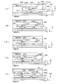
- (A), (B), (C), (D), and (E) are operation
- (A) is a figure which shows an example of the detection signal at the time of carrying in a mask case
- (B) is a figure which shows an example of the detection signal at the time of removing the upper case part of a mask case.
- (A), (B), (C), (D), (E) is operation
- (A) is a top view which shows the mask case of another modification
- (B) is an enlarged view which shows the collar part in FIG. 18
- (C) is an enlarged view which shows the other example of a collar part.
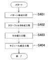
- It is a flowchart which shows an example of the manufacturing method of an electronic device.
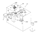
- FIG. 1 shows a schematic configuration of an exposure apparatus EX according to the present embodiment.
- the exposure apparatus EX projection exposure apparatus
- the exposure apparatus EX is a scanning exposure type, and is a flat plate coated with a resist (photosensitive agent) for manufacturing a liquid crystal display element or an organic EL (Electro-Luminescence) type display element.
- An image of the pattern of the mask M is exposed on a plate-shaped plate P (photosensitive substrate).
- the Y axis is taken along the direction in which a later-described mask case 30 in which a mask M is stored from a later-described mask library LB is carried in or out, and is orthogonal to the Y axis in the horizontal plane.
- the X axis is taken along the direction of the Z axis, and the Z axis is taken along the direction perpendicular to the X axis and the Y axis (that is, the vertical direction).
- the exposure apparatus EX includes an exposure unit S that exposes a pattern of a rectangular flat mask M onto the plate P.
- a dust-proof thin film may be stretched on the pattern surface (lower surface) of the mask M via a rectangular frame-shaped frame (not shown).
- the exposure unit S includes a mask stage MST that holds and moves the mask M, an illumination system IL that illuminates the mask M with exposure light, and a projection optical system PL that projects an image of the pattern of the mask M onto the surface of the plate P. And a plate stage PST that holds and moves the plate P.
- the exposure apparatus EX includes a mask library LB as a storage unit capable of storing a plurality of mask cases 30 each storing a mask M, and a transport apparatus H1 that carries the mask case 30 into and out of the mask library LB.
- a mask loader system H2 that transports the mask M taken out from the mask case 30 to the mask stage MST of the exposure unit S, and a control device CONT that controls the operation of the entire apparatus.
- the exposure unit S, the mask library LB, the transfer device H1, and the mask loader system H2 are accommodated in the exposure chamber CH set in a predetermined environment.
- the mask library LB is provided in the vicinity of the carry-in / out port (not shown) of the mask case 30 provided on the side surface in the + Y direction of the exposure chamber CH, and temporarily stores the plurality of storage portions 65 for storing the mask case 30 and the mask case 30.
- Temporary storage portion 66 is provided for the purpose of storage.
- the plurality of accommodating portions 65 are arranged in the Z direction, and one mask M is individually accommodated in each mask case 30 accommodated in the accommodating portion 65. Different mask patterns are usually formed on the masks M in the plurality of mask cases 30.
- many masks M different from the mask M in the mask library LB are stored in a mask stocker (not shown) outside the exposure chamber CH in a state where each mask M is housed in the mask case 30.
- the mask case 30 in which the mask M required by the exposure apparatus EX is accommodated is carried from the mask stocker by the transport vehicle V into the temporary accommodating portion 66 of the mask library LB through the entrance / exit (not shown) of the exposure chamber CH. Is done.
- the mask case 30 carried into the temporary storage unit 66 is moved to the storage unit 65 by the transfer device H1.
- the mask case 30 in which the used mask M is stored is moved from the storage unit 65 to the temporary storage unit 66 by the transfer device H1.
- the mask case 30 is returned to the mask stocker (not shown) from the temporary storage portion 66 by the transport vehicle V through the carry-in / out port (not shown) of the exposure chamber CH.
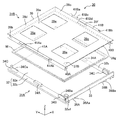
- FIG. 2A is a perspective view of the mask case 30 in FIG. 1 viewed from the top surface side
- FIG. 2B is a perspective view of the mask case viewed from the bottom surface side
- FIG. 3A shows the mask case 30.
- a plan view (top view) and FIG. 3 (B) are bottom views showing the mask case 30.
- the coordinate system (X, Y, Z) is a coordinate system in a state where the mask case 30 is accommodated in the accommodating portion 65 of the mask library LB in FIG. Show.
- the mask case 30 includes a lower case portion (first case portion) 31A on which the mask M is placed, and a mask M placed on the lower case portion 31A. And an upper case part (second case part) 31B placed (mounted) on the lower case part 31A. That is, the mask case 30 forms a space for storing the mask M by combining the lower case portion 31A and the upper case portion 31B.
- the lower case portion 31A and the upper case portion 31B are combined so as to cover (enclose) a space for storing the mask M, and protect the mask M stored in this space.
- the lower case portion 31A has a rectangular flat base member 32 larger than the mask M, and a bolt ( It has a flat plate-like side wall member 33 fixed via a not-shown).
- the upper case portion 31B has a rectangular flat plate portion (top plate portion) 39a having substantially the same size as the base member 32, the ⁇ X direction, the + X direction, and the + Y direction.
- the cover member 39 has a shape in which flat side wall portions 39b, 39c, and 39d are respectively provided on the lower side of the direction end portion, and the center portion of the side surface in the ⁇ X direction and the + X direction of the cover member 39 respectively protrudes outward.
- the outer shape of the upper surface of the mask case 30 (case portions 31A and 31B) is substantially rectangular in which the length in the Y direction is longer than the width in the X direction.
- the members constituting the lower case portion 31A and the upper case portion 31B can be formed from a metal such as aluminum or stainless steel as an example, but are not limited to metals, and are formed from a composite material using plastic or carbon fiber, etc. May be. Further, a window formed of synthetic resin, quartz glass, or the like may be mounted (embedded) in an opening (detailed later) formed in a part of the lower case portion 31A and the upper case portion 31B.
- the base member 32 protrudes in the ⁇ Y direction slightly from the flat plate portion 32a on both side surfaces in the X direction of the rectangular flat plate portion 32a, and has two elongated flat plates having a groove portion 32b1 formed along the Y direction on the bottom surface.
- the part 32b is fixed.
- a short rod-like leg 35 is fixed to two locations of the groove 32b1 of the flat plate portion 32b via bolts B4, and the leg 35 is fixed to two locations at the center of the bottom surface of the flat plate portion 32a via bolts B4.
- the leg portion 35 fixed to the flat plate portion 32a can be omitted.
- the connecting portions 38A and 38B having an L-shaped cross section are fixed by bolts (not shown) at two locations on the side surface in the ⁇ Y direction of the flat plate portion 32a (the bottom surface of the side wall member 33).
- Circular openings 38 ⁇ / b> Aa and 38 ⁇ / b> Ba are formed in portions protruding in the Y direction.
- Each of the flange portions 41A and 41B has an L-shaped cross section, and the length in the Y direction is about 1 ⁇ 2 of the length of the cover member 39.
- the flange portions 41A and 41B face the side wall portions 39b and 39c.
- the portions are fixed to the side wall portions 39b and 39c of the cover member 39 by bolts B5 at a plurality of locations.
- the portions protruding in the ⁇ X direction and the + X direction of the flange portions 41A and 41B (hereinafter, these portions are simply referred to as the flange portions 41A and 41B) are close to the end portion in the ⁇ Y direction, and each has a predetermined width in the Y direction.
- Notches 41Aa and 41Ba are provided, and circular openings (through holes) 41Ab and 41Bb having predetermined sizes are provided at positions close to the + Y-direction ends of the flanges 41A and 41B, respectively. Further, two circular openings (through holes) 41Bc and 41Bd having the same size are provided at predetermined intervals along the Y direction at a position close to the notch 41Ba of the collar portion 41B on one side (+ X direction side). ing. Specifically, as an example, the openings 41Bc and 41Bd are provided so that positions separated by 60 mm in the Y direction are opened (penetrated).
- the distance in the Y direction between the center of 41Bd and the center of the opening 41Bb is 570 mm.
- the flange portions 41A and 41B may have a configuration in which the arrangement of the above-described notch portion and each opening is reversed with respect to the Y direction.
- the openings 41Bc and 41Bd are not limited to the same size but may be different sizes, and are not limited to a circular shape, and may have other shapes.
- the openings 41Bc and 41Bd may have a cutout shape connected to the side surface of the flange portion 41B instead of the circularly closed opening (hole) shape.
- the upper case portion 31B is easily separated from the lower case portion 31A by lowering the lower case portion 31A while supporting the flange portions 41A and 41B of the upper case portion 31B. Can do. Conversely, by raising the lower case portion 31A from the state in which the upper case portion 31B is separated, the upper case portion 31B is placed on the lower case portion 31A so as to cover the mask M placed on the lower case portion 31A. Can be easily mounted.
- FIG. 4 shows the mask case 30 in a state where the upper case part 31B is separated from the lower case part 31A and the mask M is lifted from the lower case part 31A.
- support portions 34B and 34C in which step portions 34Ba and 34Ca for supporting the mask M are respectively formed are fixed to the upper end portions of two elongated flat plate portions 32b of the lower case portion 31A (one support portion). 34B is not shown), and a flat plate-like support portion 34A having the same height as the step portions 34Ba and 34Ca is fixed between the support portions 34B and 34C.
- the lower case portion 31A masks the stepped portions 34Ba and 34Ca of the pair of support portions 34B and 34C and the peripheral portion of the pattern surface (lower surface) of the mask M on the upper surface of the pair of support portions 34A. M can be supported. With the mask case 30 stored in the mask library LB, the pattern surface of the mask M is substantially parallel to the horizontal plane.
- mask observation windows 39e that transmit light are respectively attached to four openings (for example, substantially square openings) provided in the flat plate portion 39a of the cover member 39, and the flat plate portion 39a.
- a window portion 39f for observing a barcode that transmits light is attached to an opening (for example, an elongated rectangular opening) provided at an end portion in the + X direction.
- an opening for example, an elongated rectangular opening
- the opening for example, for the internal observation that transmits light (for example, visible light) to the opening (for example, a substantially square opening) provided at the ⁇ X direction end and the ⁇ Y direction end of the flat plate portion 32a of the base member 32.
- a window portion 32a1 is attached.
- the operator can observe the state of the internal mask M (including the presence or absence of the mask M) through the window portion 39e.
- a bar code (not shown) formed on the internal mask M can be read through the portion 39f.
- synthetic resin, glass eg, quartz glass, or the like can be used as a material that transmits light and generates little dust.
- the side wall portions 39b and 39c of the cover member 39 are respectively placed on regions outside the support portions 34B and 34C in the elongated flat plate portion 32b of the base member 32, and the side wall portion 39d is arranged in the + Y direction of the base member 32. It is placed in the area of the end of Further, the ⁇ Y direction end portion 39g of the flat plate portion 39a of the cover member 39 protrudes in the ⁇ Y direction from the side wall portions 39b and 39c to the extent that the side wall member 33 of the lower case portion 31A can be covered. .
- the heights of the support portions 34B and 34C are set lower than the height of the side wall member 33, and the heights of the side wall portions 39b to 39d are set slightly higher than the height of the side wall member 33.
- Portions 40A and 40B are provided.
- the positioning portions 40A and 40B are in contact with a part of the lower case portion 31A, respectively, thereby preventing the position of the upper case portion 31B from shifting in the X direction and the Y direction with respect to the lower case portion 31A due to vibration or the like. Is done.
- the positioning portions 40A and 40B may be provided not only at the ⁇ Y side end of the bottom surface of the flat plate portion 39a as described above, but also at the + Y side end portion of the bottom surface of the flat plate portion 39a. Alternatively, it may be provided at the end of the + Y side instead of the -Y side.
- a predetermined distance is provided on the bottom surface of the flat plate portion 32a of the base member 32 along the X direction (here, the width direction or the short side direction of the mask case 30).
- the first positioning portion 36A and the second positioning portion 36B are fixed.
- the first positioning portion 36A is formed with a rotationally symmetrical recess 36Aa at the center thereof
- the second positioning portion 36B is formed with a V-shaped groove-like recess 36Ba (axisymmetric recess) at the center thereof.
- a flat surface (hereinafter referred to as a flat surface) 36Ca is provided at positions PS2, PS1, PS4, and PS3 at predetermined intervals in the + Y direction and the ⁇ Y direction from the positioning portions 36A and 36B on the bottom surface of the flat plate portion 32a, respectively.
- the positioning portions 36C are fixed.
- the recess 36Aa of the positioning portion 36A has a conical surface shape.
- the concave portion 36Aa may be spherical.
- the positioning portion 36A (the same applies to the other positioning portions 36B and 36C) is fixed to the bottom surface of the flat plate portion 32a using, for example, a plurality of bolts B4.
- the center of gravity of the mask case 30 in the state where the mask M is accommodated is a straight line connecting the centers of the positioning portions 36A and 36B and a straight line connecting the centers of the two positioning portions 36C on the + Y direction side.
- the mask case 30 can be stably supported. Even in these cases, in consideration of the case where the mask case 30 is inclined due to vibration or the like, the ball transfer support members are arranged at predetermined intervals so as to face the positioning portions 36C of the other positions PS3 and PS4. May be.
- a reflection portion 37A that reflects a light beam for detecting the presence or absence of the lower case portion 31A is provided near the window portion 32a1 of the flat plate portion 32a of the base member 32.
- the reflection part 37A is a retroreflective member, and the light beam incident on the reflection part 37A is reflected in the incident direction. For this reason, even if the lower case portion 31A is inclined, the presence or absence of the lower case portion 31A can be accurately detected by the detection unit (not shown).
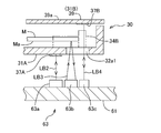
- FIG. 7 which is a cross-sectional view of a portion including the window portion 32a1 of the mask case 30 in FIG. 2 (B)
- a reflection portion 37B that reflects the light beam LB4 for detecting the presence or absence of the upper case portion 31B is provided.
- a polarizing plate (not shown) whose polarization direction is the width direction of the mask case 30, for example, is fixed on the surface of the reflection part 37B, and the reflection part 37B has polarization characteristics.
- the reflection part 37B may be a retroreflective member having no polarization characteristic, and the reflection part 37A may have a non-recursive polarization characteristic. Alternatively, each of the reflection portions 37A and 37B may have both recursion and polarization characteristics.
- the window portion 32a1 is also used to pass the light beam LB3 irradiated from the outside of the mask case 30 to detect the presence or absence of the mask M (or the distance from the detection portion to the pattern surface Ma of the mask M).
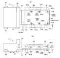
- FIGS. 5A and 5B show the transport vehicle V moving in the Y direction in order to carry in or out the mask case 30 with respect to the mask library LB of FIG.
- the transport vehicle V can be moved in the Z direction by a main body 55, a plurality of wheels 56 that are driven by a driving mechanism (not shown) to move the main body 55, and a driving mechanism (not shown) on the front surface of the main body 55.
- a mask case transport section 53 supported by the head.
- the drive mechanism has an encoder (not shown) that measures the position in the Z direction (Z position) of the mask case 30 supported by the mask case transport unit 53.
- the longitudinal direction of the flat plate portion 53a and the longitudinal direction of the mask case 30 are parallel to the flat plate portion 53a having a rectangular upper surface substantially parallel to the horizontal plane of the mask case transporting portion 53.
- Mask case 30 is placed. 5A and 5B, the longitudinal direction of the flat plate portion 53a is the Y direction, and the width of the flat plate portion 53a in the X direction is smaller than the width of the flat plate portion 32a of the base member 32 of the mask case 30.
- the moving direction of the main body 55 can be controlled by a plurality of wheels 56, and the main body 55 is also provided with a mechanism (not shown) for adjusting the position of the mask case transporter 53 in the X direction. Yes.
- Ball transfers 54A, 54B, 54C, and 54D which are support members having spherical portions 54Aa, 54Ba, 54Ca, and 54Da provided on the surface, are fixed by bolts (not shown). Further, in the same positional relationship as the openings 38Aa and 38Ba of the connecting portions 38A and 38B with respect to the positioning portions 36A and 36B of FIG.
- the support portions 57A and 57B having pins 57Aa and 57Ba having a smaller diameter than the openings 38Aa and 38Ba are fixed.
- the concave portions 36Aa and 36Ba of the positioning portions 36A and 36B of the mask case 30 and the flat portion 36Ca of the positioning portion 36C of the position PS1 are respectively ball transfer 54A and 54B.
- 54C are in contact with the spherical surface portions 54Aa, 54Ba, 54Ca.
- the heights of the ball transfers 54A to 54C of the mask case transport section 53 are individually adjusted so that the bottom surface of the flat plate portion 32a of the mask case 30 is substantially parallel to the horizontal plane.
- the center of the spherical surface portion of the ball transfer 54A of the mask case transporting portion 53 is obtained.
- the center of the concave portion 36Aa of the positioning portion 36A coincide with each other, and the Y-direction position of the center of the spherical surface portion of the ball transfer 54B matches the Y-direction position of the center of the concave portion 36Ba of the positioning portion 36B.
- the position and rotation angle of the mask case 30 are automatically adjusted by the weight of 30. For this reason, it is not necessary to make the position control accuracy very high when the mask case 30 is placed on the mask case transport unit 53.
- the height of the ball transfer 54D is adjusted such that the spherical surface portion 54Da of the ball transfer 54D is positioned at a slight distance from the positioning portion 36C at the position PS2. Similarly, the position PS3.
- Another ball transfer (not shown) may be provided on the upper surface of the flat plate portion 53a with a slight gap from the positioning portion 36C of PS4.
- the concave portions 36Aa, 36Ba and the flat portion 36Ca are supported by the ball transfers 54A to 54C, respectively, so that the position of the mask case 30 in the X direction and the Y direction with respect to the mask case transport portion 53 (transport vehicle V) is parallel to the Z axis.
- the rotation angle around the axis (hereinafter referred to as the ⁇ z direction) is automatically set to the target value, and the mask case 30 is stably conveyed by the conveyance vehicle V in this state.
- the ball transfer 54D is arranged close to the positioning portion 36C at the other position PS2, even if the mask case 30 is inclined due to vibration or the like, the positioning portion 36C comes into contact with the ball transfer 54D, so that The inclination angle does not increase any more.
- the pins 57Aa and 57Ba of the mask case transport section 53 are inserted into the openings 38Aa and 38Ba of the connecting portions 38A and 38B of the mask case 30, the position of the mask case 30 may be shifted due to vibration during transport. It can be surely prevented.
- a non-contact type distance sensor (not shown) that detects the distance to the side surface of the mask case transport unit 53 of the transport vehicle V is installed outside the exposure chamber CH at two locations separated in the Y direction. ing. Then, when the position in the X direction and the rotation angle in the ⁇ z direction of the mask case 30 placed on the mask case transport unit 53 become the target values when they are housed in the mask library LB, the two positions
- the interval detected by the interval sensor is stored as an adjustment target value, for example, in the storage unit of the control device CONT.
- the transport vehicle V includes an encoder (not shown) that measures the position of the mask case 30 supported by the mask case transport unit 53 in the Y direction.
- the relationship between the position in the Y direction of the mask case 30 measured by this encoder and the target position in the Y direction in the temporary storage unit 66 in the mask library LB is known.
- the transport vehicle V is moved in the ⁇ Y direction and supported by the mask case transport section 53.
- the mask case 30 can be transferred to the temporary storage unit 66 by moving the mask case 30 above the temporary storage unit 66 of the mask library LB and then lowering the mask case transport unit 53.
- the mask case transport unit 53 is moved to the bottom surface side of the mask case 30 held in the temporary storage unit 66, the mask case is removed from the temporary storage unit 66 by increasing the Z position of the mask case transport unit 53.
- the mask case 30 can be delivered to the transport unit 53 (the transport vehicle V).
- the transport apparatus H1 includes a mask case transport unit 61 on which the mask case 30 is placed, a holding unit 64 that holds an end of the mask case transport unit 61 in the -Y direction, and a mask case transport unit via the holding unit 64.
- the horizontal drive part 67 which moves 61 to a Y direction, and the raising / lowering drive part 68 which moves the mask case conveyance part 61 to a Z direction via the horizontal drive part 67 are provided.
- the elevating drive unit 68 has an encoder (not shown) that measures the Z position of the mask case 30 supported by the mask case transport unit 61.
- the horizontal drive unit 67 has an encoder (not shown) that measures the position of the mask case 30 supported by the mask case transport unit 61 in the Y direction.
- the relationship between the position in the Y direction of the mask case 30 measured by this encoder and the target position in the Y direction in each storage unit 65 in the mask library LB is known.
- the mask case is arranged so that the longitudinal direction of the mask case transport section 61 and the longitudinal direction of the mask case 30 are parallel to the mask case transport section 61 having a rectangular upper surface substantially parallel to the horizontal plane and having the Y direction as the longitudinal direction. 30 is placed.
- the width in the X direction of the mask case transport unit 61 is set to be narrower than the width of the flat plate portion 32 a of the base member 32 of the mask case 30.
- the ball transfer 62A, 62B, 62C, 62D which is a support member provided with spherical portions 62Aa, 62Ba, 62Ca, 62Da on the surface, is fixed by bolts (not shown). Further, the mask case 30 is positioned at a position away from the ball transfer 62 on the upper surface of the mask case transporting portion 61 in the ⁇ Y direction with the same positional relationship as the reflecting portion 37A and the window portion 32a1 with respect to the positioning portion 36B of FIG. A detection device 63 is provided.
- the concave portions 36Aa and 36Ba of the positioning portions 36A and 36B of the mask case 30 and the flat portion 36Ca of the positioning portion 36C of the position PS1 are respectively ball transfer 62A and 62B.
- 62C are in contact with the spherical surface portions 62Aa, 62Ba, 62Ca.
- the heights of the ball transfers 62A to 62C of the mask case transport unit 61 are individually adjusted so that the bottom surface of the flat plate portion 32a of the mask case 30 is substantially parallel to the horizontal plane.
- the center of the spherical surface portion of the ball transfer 62A of the mask case transporting portion 61 is obtained.
- the center of the concave portion 36Aa of the positioning portion 36A coincide with each other, and the Y-direction position of the center of the spherical portion of the ball transfer 62B matches the Y-direction position of the center of the concave portion 36Ba of the positioning portion 36B.
- the position and rotation angle of the mask case 30 are automatically adjusted by the weight of 30.
- the height of the ball transfer 62D is adjusted so that the spherical surface portion 62Da of the ball transfer 62D is positioned at a slight distance from the positioning portion 36C at the position PS2.
- the position PS3 may be provided on the upper surface of the mask case transport section 61 with a slight gap from the positioning section 36C of PS4.
- the mask case 30 is stably transported by the mask case transport section 61.
- the ball transfer 62D is arranged close to the positioning portion 36C at the other position PS2, even if the mask case 30 is inclined due to vibration or the like, the positioning portion 36C comes into contact with the ball transfer 62D, so that The inclination angle does not increase any more.
- the reflection portion 37 ⁇ / b> A and the window portion 32 a 1 of the mask case 30 face the detection device 63.
- the detection device 63 irradiates the retroreflecting part 37 ⁇ / b> A of the lower case part 31 ⁇ / b> A of the mask case 30 with the light beam LB ⁇ b> 2 and detects the intensity of the reflected light from the reflecting part 37 ⁇ / b> A.
- a second detection unit 63b that irradiates the pattern surface Ma of the mask M obliquely with the light beam LB3 through the window part 32a1 and detects the intensity of the light reflected by the pattern surface Ma and returned through the window part 32a1;
- a third detector 63c that detects the intensity of light reflected by the reflector 37B and returned through the window 32a1 by irradiating the reflector 37B having the polarization characteristics of the inner surface of the upper case 31B through the window 32a1.
- the light beams LB2 to LB4 are light beams in the visible range emitted from light emitting diodes (LEDs) or the like converted into parallel light beams by a collimator lens (not shown). Light in the infrared region or the like may be used.
- the window portion 32a1 is formed of a material that transmits light from the near infrared region to the infrared region.
- the presence or absence of the lower case portion 31A can be detected by comparing the intensity detected by the detection unit 63a with a predetermined first reference value by a signal processing unit (not shown). Further, by applying the intensity detected by the detection unit 63b to a predetermined table (a table showing the correspondence between the signal intensity and the distance to the test object) by the signal processing unit (not shown), the pattern from the detection unit 63b is obtained. The distance to the surface Ma and / or the presence or absence of the mask M can be detected.
- the presence or absence of the upper case portion 31B can be detected by comparing the intensity detected by the detection unit 63c with a predetermined second reference value by a signal processing unit (not shown). Detection results such as the presence or absence of the mask case 30 using the detection device 63 are supplied to the control device CONT. Note that at least one of the detectors 63a to 63c may be provided.
- the mask case transport unit 61 is also provided with support portions similar to the support portions 57A and 57B having the pins 57Aa and 57Ba of the transport vehicle V, and the pins (not shown) of the support portions are connected to the connecting portions 38A of the mask case 30. , 38B may be inserted into the openings 38Aa, 38Ba to prevent displacement of the mask case 30 due to vibration or the like.
- the mask case transport unit 61 In a state where the Z position of the mask case 30 supported by the mask case transport unit 61 by the elevating drive unit 68 is set higher than the set value in the storage unit 65 (or the temporary storage unit 66) where the mask library LB is located, After the mask case transport unit 61 is moved in the + Y direction by the drive unit 67 and the mask case 30 supported by the mask case transport unit 61 is moved above the storage unit 65 (or the temporary storage unit 66), the mask case By lowering the transport unit 61, the mask case 30 can be transferred to the storage unit 65 (or the temporary storage unit 66).
- the mask case transport unit 61 Conversely, by moving the mask case transport unit 61 to the bottom side of the mask case 30 held in a certain storage unit 65 (or the temporary storage unit 66), the Z position of the mask case transport unit 61 is increased, The mask case 30 can be delivered from the storage unit 65 (or the temporary storage unit 66) to the mask case transport unit 61 (transport device H1).
- FIGS. 8 and 10 are perspective views showing the mask library LB, respectively.
- FIG. 9 is a view of the mask library LB in the + Y direction.
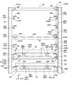
- the mask library LB connects a plurality of rod-shaped members parallel to the X direction, the Y direction, and the Z direction (for convenience of explanation, some members are represented by two-dot chain lines).
- a box-shaped frame mechanism 43 configured in parallel, a pair of rails 45A and 45B having the same Z position fixed to the lowermost stage of the frame mechanism 43 in the Y direction, and the frame mechanism 43 above the rails 45A and 45B.
- Each of the rails 45A, 45B and 46A, 46B has an L-shaped cross section, and a portion having a side surface orthogonal to the upper surface so that the upper surface is substantially parallel to the horizontal plane and is opposed to each other is a bolt (not shown). ) To the inner surface of the frame mechanism 43.
- the lengths of the rails 45A, 45B and 46A, 46B in the Y direction are set slightly longer than the length of the mask case 30 in the Y direction, the distance between the upper surface of the rails 45A, 45B and the partition plate 44, and the positions P1 ⁇
- the distance in the Z direction between the upper surfaces of the rails 46A and 46B adjacent to each other in the Z direction of P5 is set wider than the height of the mask case 30.
- the width of the outer shape in the X direction of the rails 45A, 45B and 46A, 46B is set wider than the width in the X direction of the outer shape of the flange portions 41A, 41B of the mask case 30, and the rails 45A, 45B and 46A, 46B
- the interval in the X direction is set to be substantially the same as the width in the X direction of the flat plate portion 32a of the lower case portion 31A of the mask case 30 (the interval between the two flat plate portions 32b to which the leg portions 35 are fixed).
- the two leg portions 35 in the ⁇ X direction of the lower case portion 31A of the lower case portion 31A of the mask case 30 are respectively formed on the upper surfaces of the pair of rails 45A and 45B and the upper surfaces of the pair of rails 46A and 46B at the positions P1 to P5.
- Two legs 35 in the + X direction can be placed.
- a temporary accommodating portion 66 is configured including a pair of rails 45A and 45B
- an accommodating portion 65 is configured including a pair of rails 46A and 46B at positions P1 to P5.
- the accommodating portions 65 are arranged in five stages of positions P1 to P5, but the number of accommodating portions 65 can be increased or decreased.
- the rails 46A and 46B and the rails 45A and 45B have the same shape and are installed at the same positions in the X direction and the Y direction.
- the positional relationship between the mask library LB and the transfer device H1 is such that the mask case 30 is positioned on the spherical surface portions 62Aa, 62Ba, and 62Ca of the ball transfers 62A, 62B, and 62C of the mask case transfer unit 61 of the transfer device H1 of FIG.
- the two legs 35 of the mask case 30 on the rails 46A and 46B at the corresponding positions P1 to P5 respectively correspond to the ⁇ X direction and the + X direction. It is set to be located at the target position in the X direction.
- the width in the X direction of the mask case transport unit 61 is set to be smaller with a margin than the interval in the X direction between the rails 46A and 46B. For this reason, the Z position of the bottom surface of the leg portion 35 of the mask case 30 is set higher than the upper surfaces of the rails 46A and 46B at the positions P1 to P5 by the transfer device H1, and the Y direction of the mask case 30 (mask library LB) is set. After the position in the carry-in / out direction) is set to a predetermined target position, the mask case 30 is lowered, so that the four leg portions can be easily placed on the rails 46A and 46B (accommodating portions 65) at the positions P1 to P5.
- the mask case 30 can be placed (accommodated) via 35. Similarly, the mask case 30 can be placed on the rails 45 ⁇ / b> A and 45 ⁇ / b> B (temporary storage portion 66) by the transfer device H ⁇ b> 1. Furthermore, the mask case 30 can be carried out from the storage unit 65 or the temporary storage unit 66 by the reverse operation of the transfer device H1. Instead of providing the rails 45A and 45B in the temporary storage portion 66, the transport vehicle V may be provided with similar rails. Accordingly, the mask case can be directly transferred between the transport vehicle V and the transport device H1 without temporarily transferring the mask case to the temporary storage unit 66.
- proximity sensors 50A capable of detecting the X-direction and Y-direction intervals to the side surfaces of the mask case 30 in a non-contact manner are installed at the + Y-direction ends of the upper surfaces of the rails 45A and 46A on the ⁇ X-direction side
- Proximity sensors 50B capable of detecting the X-direction and Y-direction distances to the side surfaces of the mask case 30 in a non-contact manner are installed at the + Y-direction ends of the upper surfaces of the rails 45B and 46B on the + X-direction side, respectively.
- Proximity sensors 51 that can detect the distance in the X direction to the side surface of the mask case 30 in a non-contact manner are installed at the end portions in the ⁇ Y direction on the upper surface of 46B.
- the proximity sensors 50A, 50B, 51 are, for example, optical.
- Information about the position of the mask case 30 (the X direction, the position in the Y direction, and the rotation angle in the ⁇ z direction) in the temporary storage unit 66 and the storage unit 65 detected by the proximity sensors 50A, 50B, 51 is supplied to the control unit CONT.
- the position of the mask case 30 thus detected deviates from a predetermined target value beyond an allowable range, as an example, the position and / or rotation angle of the mask case 30 by the transport vehicle V or the transport device H1.
- At least one of the proximity sensors 50A, 50B, and 51 may be moved to the end portion in the ⁇ Y direction, and the proximity sensors 50A and 50B may be arranged at end portions on the opposite sides with respect to the Y direction.
- support portions 47A1, 47A2, and 47B1 which support the flange portions 41A and 41B of the mask case 30 accommodated in the accommodating portions 65 of the positions P1 to P4, respectively, at two positions of the rails 46A and 46B at the positions P2 to P5. 47B2 are attached so as to face each other, and the collar portion 41A of the mask case 30 accommodated in the accommodation portion 65 of the uppermost stage (position P5) is provided at two locations of two portions parallel to the Y direction at the upper end of the frame mechanism 43, and Support portions 47C1, 47C2 and 47D1, 47D2 for supporting 41B are attached to face each other.
- One of the support portions 47A1 and 47B1 attached to the rails 46A and 46B at the positions P2 to P5 is located in the notches 41Aa and 41Ba of the flange portions 41A and 41B of the mask case 30 with respect to the direction along the plane).
- the other support portions 47A2 and 47B2 are close to the ⁇ Y-direction ends of the flange portions 41A and 41B.
- the Z positions of the support portions 47A1 to 47B2 are set higher than the upper surfaces of the corresponding flange portions 41A and 41B.
- pins 48 that can be inserted into the openings 41Ab and 41Bb of the flange portions 41A and 41B are fixed to the upper surfaces of the other support portions 47A2 and 47B2.
- the diameter of the pin 48 is set smaller than the diameter of the openings 41Ab and 41Bb with a larger clearance than the positioning accuracy of the mask case 30 by the transfer device H1.
- the positions of the support portions 47C1, 47C2, 47D1, and 47D2 in the XY plane are the same as those of the support portions 47A1, 47A2, 47B1, and 47B2, and the pins 48 are also fixed to the upper surfaces of the support portions 47C2 and 47D2, respectively. .
- the mask case 30 on the rails 46A and 46B at the positions P1 to P5 is raised by the transport device H1 so that the support portions 47A1 and 47B1 pass through the notches 41Aa and 41Ba, respectively, and the mask case 30 is further raised. Is moved in the ⁇ Y direction by the width in the Y direction of the notches 41Aa and 41Ba of the flange portions 41A and 41B so that the openings 41Ab and 41Bb are positioned above the pins 48, and then the mask case 30 is moved.
- the flange portions 41A, 41B of the upper case portion 31B are respectively provided with support portions 47A1, 47A2, 47B1, 47B2 or uppermost support portions 47C1, 47C2, 47D1, provided on the rails 46A, 46B at positions P2 to P5.
- 47D2 supports the upper case 31B from the lower case 31A.
- the pins 48 of the support portions 47A2, 47B2 or 47C2, 47D2 are inserted into the openings 41Ab, 41Bb of the flange portions 41A, 41B, respectively, it is possible to prevent the positions of the flange portions 41A, 41B from being displaced due to vibrations or the like. it can.
- the upper case portion 31B can be easily and accurately positioned on the lower case portion 31A.
- the opening 41Ab, 41Bb of the collar part 41A, 41B and the pin 48 of the support part 47A2, 47B2, 47C2, 47D2 may be omitted.
- the openings 41Ab and 41Bb are not limited to the shape of the opening through which the pin 48 is inserted, and may be any shape that fits with the pin 48.
- the upper surface sides of the flange portions 41A and 41B are closed. It can also be a hole (not open), that is, a hole that does not penetrate (concave).
- the detection device 52 of the mask case 30 is fixed to the upper surface of the end portion in the + X direction of the partition plate 44, and the light beam LB ⁇ b> 1 is irradiated upward in parallel with the Z direction from the detection device 52.
- the reflection member 49 and the detection device 52 are a part of the transport device H1.
- the rails 46B on the + X direction side of the positions P1 to P5 are each formed with an opening 46Ba through which the light beam LB1 passes. As shown in FIG.
- the detection device 52 includes a light source unit 52a that emits a light beam, a beam splitter 52b that reflects a part of the light beam (light beam LB1) emitted from the light source unit 52a in the + Z direction, A photoelectric sensor 52c such as a photodiode that receives and photoelectrically converts a light beam transmitted through the beam splitter 52b out of the light beam LB1 reflected by the reflecting member 49 is provided.
- a signal processing unit not shown
- the arrangement of the light source unit 52a and the photoelectric sensor 52c may be switched so that the beam splitter 52b transmits the light beam from the light source unit 52a, and the photoelectric sensor 52c detects the light beam reflected by the beam splitter 52b.
- the reflection member 49 may have a polarization characteristic similar to the above-described reflection portion 37B, or a straight line in which the light beam directed toward the reflection member 49 and the light beam reflected by the reflection member 49 are orthogonal to each other.
- a polarizing element such as a quarter-wave plate or a polarizer may be disposed in the optical path of the light beam so as to be polarized.
- the beam splitter 52b may have a polarization characteristic to be a polarization beam splitter.
- the position away from the notch 41Ba of the flange 41B is set so that the light beam LB1 passes through the opening 41Bd.
- the upper case portion 31B of the mask case 30 is moved by, for example, the support portions 47A1, 47A2, and 47B1, 47B2 or the support portions 47C1, 47C2, and 47D1 at the position P3 (or positions P2, P4, P5) by the transport device H1.
- the upper case portion 31B is positioned so that the light beam LB1 passes through the opening 41Bc (see FIG. 2A) located near the notch portion 41Ba of the flange portion 41B. Is done.
- the detection device 52 can detect the absence of an object in the optical path of the light beam LB1.
- the mask case 30 and / or the upper case portion 31B are positioned within a predetermined allowable range with respect to the housing portion 65 (target position). Can do.
- the accommodation state of the mask case 30 and / or the upper case part 31B with respect to the accommodation part 65 can be detected.
- the light beam LB1 cannot pass through the openings 41Bc and 41Bd of the flange portion 41B and is detected.
- the device 52 can detect the presence of an object (the collar portion 41B) in the optical path of the light beam LB1. That is, when the light beam LB1 cannot be detected by the detection device 52, the mask case 30 and / or the upper case portion 31B is positioned beyond the allowable range with respect to the target position (that is, is displaced). Can be detected.
- the accommodation state of the mask case 30 and / or the upper case portion 31B with respect to the accommodation portion 65 can be detected. Therefore, as an example, when the mask case 30 is transported to the accommodating portion 65 by the transport device H1, or when the upper case portion 31B of the mask case 30 is placed on the corresponding support portions 47A1 to 47B2, etc., detection is performed. By adjusting the position of the mask case 30 or the upper case portion 31B so that the light beam LB1 can be detected by the device 52, the mask case 30 or the upper case portion 31B can be easily installed at the target position.
- the plurality of members constituting the lower case portion 31A and the upper case portion 31B may be connected by welding, bonding, integral molding or the like in addition to the connection by bolts.
- the mask case 30 in which the mask M is stored is transported from the mask stocker (not shown) by the transport vehicle V to the mask library LB of the exposure apparatus EX (step 102). That is, the mask case transport section 53 so that the concave portions 36Aa and 36Ba and the flat section 36Ca of the positioning sections 36A to 36C of the mask case 30 are in contact with the spherical surfaces of the ball transfers 54A to 54C of the mask case transport section 53 of the transport vehicle V.
- the mask case 30 is placed on the surface.
- the transport vehicle V is positioned so that the position in the X direction and the angle in the ⁇ z direction of the mask case 30 are the target values in the temporary storage unit 66, respectively, and the Z position of the mask case 30 is set higher than the set value.
- the unloading population (not shown) of the exposure chamber CH is opened by an unillustrated opening / closing mechanism, and the mask case 30 supported by the mask case transporting unit 53 through the unloaded population of the transport vehicle V is moved to the rails 45A and 45B of the mask library LB. Move up. Further, as shown in FIG.
- the proximity sensors 50A, 50B, 51 on the rails 45A, 45B detect the position of the mask case 30 in the X direction, the Y direction, and the rotation angle in the ⁇ z direction, and the control unit CONT determines the detection results in advance. It may be compared with a certain target value. And when the deviation
- the transfer device H1 is moved to the position of the mask case transfer unit 53 shown in FIG.
- the mask case transport unit 61 is moved.
- the mask case transport section 61 is raised so that the spherical surface portions of the ball transfers 62A to 62C of the mask case transport section 61 come into contact with the recesses 36Aa and 36Ba and the flat portion 36Ca of the positioning sections 36A to 36C of the mask case 30.
- the mask case 30 is delivered to the mask case transport unit 61.
- the lower case portion 31A of the mask case 30, the mask M, and The presence or absence of the upper case portion 31B (or the distance to the mask M) may be detected.
- the process proceeds to step 122 and the mask case 30 is moved. To return.
- control information is supplied to the transport device H1 so that the mask case 30 is returned to the temporary storage unit 66, and the mask case 30 is carried out of the exposure chamber CH to the transport vehicle V.
- Control information is supplied as follows.
- the mask case 30 is carried out of the exposure chamber CH.
- the operation returns to step 102.
- another mask case 30 exchanged with the returned mask case 30 is carried into the temporary accommodating portion 66 by the transport vehicle V.
- the mask case 30 in which another mask M is stored or the mask case 30 without the mask M is erroneously stored in the storage unit 65 of the mask library LB.
- the mask M is not present at the stage where the transport device H1 delivers the mask M to the mask loader system H2, and the mask transport failure can be prevented.
- the operator can accurately confirm that the lower case portion 31A, the mask M, and the upper case portion 31B exist outside the exposure chamber CH (or that the distance to the mask M is within an allowable range). In such a case, the confirmation (step 120) by the detection device 63 may be omitted.
- step 120 when it is determined that the lower case portion 31A, the mask M, and the upper case portion 31B are all present (or the distance to the mask M is within an allowable range), or confirmation by the detection device 63 is omitted.
- the process proceeds to step 104, and the mask case 30 is moved to the accommodating portion 65 at, for example, the position P1 of the mask library LB by the transport device H1. That is, the mask case transport unit 61 that supports the mask case 30 is moved in the ⁇ Y direction, and the mask case transport unit 61 is raised so that the Z position of the mask case 30 is, for example, above the rails 46A and 46B at the position P1.
- the mask case transport unit 61 moves above the rails 46A and 46B at the position P1. Further, as indicated by a two-dot chain line in FIG. 9, the leg portions 35 of the mask case 30 are placed on the rails 46A and 46B at the position P1 by lowering the mask case transport portion 61 of the transport device H1. The As a result, the mask case 30 is moved from the temporary housing portion 66 to the housing portion 65 at the position P1.
- FIG. 12 For convenience of explanation, as shown by a two-dot chain line in FIG. 12, it is assumed that the mask case 30 is moved on the rails 46A and 46B (accommodating portion 65) at the position P2, and the mask is moved from the accommodating portion 65 at the position P2. It is assumed that the mask M in the mask case 30 is transferred to the stage MST.
- FIGS. 12 and 13 for convenience of explanation, a part of the frame mechanism 43 and the flange 41 ⁇ / b> B of the mask case 30 are shown in cross section. At this time, in FIG.
- the light beam LB1 emitted from the detection device 52 is detected by the detection device 52 through the opening 41Bd of the flange portion 41B of the mask case 30 and the reflection member 49, and the flange portion 41A.
- the mask case 30 is positioned such that the support portions 47A1 and 47B1 at the position P3 are positioned above the cutout portions 41Aa and 41Ba of the terminal 41B (see FIG. 3A).
- the mask case transfer unit 61 can be efficiently positioned in a short time with respect to the mask case 30.
- the mask case conveyance part 61 of the conveying apparatus H1 After moving the mask case conveyance part 61 of the conveying apparatus H1 to the downward direction of the bottom face of the mask case 30 of the accommodating part 65 of the position P2, the mask case conveyance part 61 is raised, and the positioning part of the mask case 30 to be used is used.
- the spherical surface portions 62Aa and 62Ba (convex portions) of the ball transfers 62A and 62B of the mask case transporting portion 61 are brought into contact (engaged) with the concave portions 36Aa and 36Ba of 36A and 36B, and the flat portion 36Ca of the positioning portion 36C of the mask case 30 is obtained.
- the spherical surface portion 62Ca of the ball transfer 62C is brought into contact (engaged) with (step 106).
- the mask case transport section 61 (mask case 30) is further raised so that the cutout portions 41Aa and 41Ba of the collar portions 41A and 41B pass through the support portions 47A1 and 47B1, and then, as indicated by the arrow A1, After the mask case 30 is slid in the ⁇ Y direction by the width in the Y direction of the notches 41Aa and 41Ba, the mask case 30 is lowered as indicated by the arrow A2 (step 108).
- the flange portions 41A and 41B of the upper case portion 31B of the mask case 30 are placed on the support portions 47A1, 47A2 and 47B1, 47B2 at the position P3, Only the case part 31A is placed on the mask case transport part 61, and the upper case part 31B is separated from the lower case part 31A. Further, the pins 48 of the support portions 47A2 and 47B2 are inserted into the openings 41Ab and 41bb of the flange portions 41A and 41B.
- step 130 of FIG. 11C following step 108 the control device CONT detects the light beam LB1 emitted from the detection device 52 by the detection device 52 via the reflecting member 49. You may check if.
- the light beam LB1 passes through the opening 41Bc of the flange portion 41B of the upper case portion 31B, that is, the upper case portion 31B is accurately positioned.
- the mask case transport portion 61 lower By moving the case portion 31A and raising the lower case portion 31A, the lower case portion 31A can be efficiently and accurately placed on the upper case portion 31B (in a short time).
- step 130 when the light beam LB1 is detected by the detection device 52, the operation proceeds to step 110.
- step 132 the upper case portion 31B is raised again by the mask case transport unit 61, and the upper case portion 31B is moved to the upper case portion 31B.
- step 132 the position of the mask case transport section 61 in the Y direction is adjusted so that the light beam LB1 is detected by the detection device 52, and then the mask case transport section 61 (lower case section 31A) is lowered.
- the process proceeds to step 110 in a state where the light beam LB1 is detected by the detection device 52.
- the operations in steps 130 and 132 may be performed in the middle of step 108 (after the sliding movement of the mask case 30 in the ⁇ Y direction).
- step 110 as indicated by an arrow A3, the lower case portion 31A is slid in the -Y direction via the mask case transport portion 61, and the lower case portion 31A is pulled out from the mask library LB, and then the mask case transport portion.
- 61 (lower case portion 31A) is raised to a position CA1 (see FIG. 1) which is the uppermost portion of the transport device H1.
- the mask M is transferred from the mask case transport section 61 of the transport apparatus H1 to the carrier 21 of the mask loader system H2 (step 112).
- the positioning portions 36A and 36B of the lower case portion 31A are positioned with respect to the ball transfer 62A and 62B of the mask case transport portion 61, and the carrier 21 and the mask case transport portion 61 (ball transfer 62A and 62B) Are accurately positioned with respect to each other, the carrier 21 can efficiently receive the mask M from the mask case transport section 61.
- the carrier 21 receives the mask M by, for example, a vacuum suction mechanism.
- the vacuum suction mechanism has a vacuum suction hole provided on the bottom surface of the carrier 21 and a vacuum pump (not shown) connected to the vacuum suction hole via a pipe (not shown). By switching off, the suction holding and holding release of the mask M can be switched. Then, the mask M is transported above the mask stage MST by the mask loader system H2 and loaded onto the mask stage MST (step 114).
- the carrier 21 can move between the position CA1 and the position CA2 while being supported by the carrier guide portion 21A while holding the mask M, and can move in the Z direction together with the carrier guide portion 21A. That is, the carrier 21 is provided to be movable in the X direction and the Z direction in FIG.
- the carrier 21 receives the mask M from the lower case portion 31A supported by the transfer device H1 at the position CA1, and then transfers the mask M to the position CA2.
- the carrier 21 that has moved to the position CA2 passes the mask M to the load arm 22 at the position CA2.
- the load arm 22 and the unload arm 23 are movable in the Y direction and the Z direction in FIG.
- the load arm 22 and the unload arm 23 can be individually moved in the Y direction between the position CA2 and the mask stage MST, and can be moved integrally while being supported by the Z-axis guide portion 22A in the Z direction. It has become.
- the load arm 22 and the unload arm 23 have a vacuum suction hole for holding the mask M, and perform suction holding and holding release of the mask M by turning on / off a connected vacuum pump.
- the load arm 22 receives the mask M used for the exposure process from the carrier 21 at the position CA2 and transports the mask M to above the mask stage MST, and then loads the mask M onto the mask stage MST.
- the pattern image of the mask M is exposed on the plate P having a predetermined lot number (step 116).
- the mask M that has been subjected to the exposure processing in the exposure unit S is returned to the mask library LB by the mask loader system H2 and the transport device H1 (step 118). That is, the mask M is unloaded from the mask stage MST by the unload arm 23 and conveyed to the position CA2.
- the mask M transferred to the position CA2 is transferred to the carrier 21 waiting at the position CA2, and is transferred to the position CA1 by the carrier 21.
- the mask M transported to the position CA1 is placed on the lower case portion 31A placed on the mask case transporting portion 61 of the transport device H1 that has been waiting at the position CA1.
- the mask case transport section 61 (the lower case section 31A on which the mask M is placed) is moved to the height of the storage section 65 stored before the exposure process, and the mask case transport section 61 is moved to the upper case shown in FIG. Slide and move in the + Y direction to a position below the portion 31B.
- FIG. 1 After the mask case transporting part 61 (lower case part 31A) is raised and the upper case part 31B supported by the support parts 47A1, 47A2, 47B1, 47B2 is placed on the lower case part 31A, FIG.
- the mask case transporting portion 61 By moving the mask case 30 (the lower case portion 31A and the upper case portion 31B) by the mask case transporting portion 61 in the direction opposite to the arrow A1, the mask case 30 is placed on the rails 46A and 46B (accommodating portion 65) at the position P2. Returned.
- the temporary accommodating part is conveyed by the conveyance vehicle V.
- 66 mask cases 30 may be carried out of the exposure chamber CH.
- the positioning of the mask case 30 and the mask case transport section 61 of the transport apparatus H1 is automatically performed using the positioning portions 36A and 36B of the lower case section 31A of the mask case 30 that stores the mask M.
- the mask case 30 is carried into and out of the mask library LB by the transfer device H1, and the mask M is transferred between the transfer device H1 and the mask loader system H2 (carrier 21).
- the apparatus EX performs sequential exposure using a plurality of masks M, it is possible to reduce the transport failure of the mask M between the mask library LB and the mask stage MST.
- the mask case 30 in which the mask M of the present embodiment is accommodated has the lower case portion 31A (first case portion) having the base member 32 (bottom surface) on which the support portions 34B and 34C for supporting the mask M are provided. And an upper case portion 31B (second case portion) having a flat plate portion 39a (upper surface) provided detachably with respect to the lower case portion 31A and arranged to face the base member 32, and a mask library LB (storage) It is a mask case that can be stored in the device.
- the upper case portion 31B has a collar portion 41B (holding portion) that is used when being removed from the lower case portion 31A and held in the mask library LB.
- the opening 41Bd first light passage portion
- An opening 41Bc second light passage portion through which the light beam LB1 passes when the flange portion 41B of the upper case portion 31B is in the second position held by the support portions 47B1 and 47B2 of the mask library LB; It has.
- the mask case 30 of the present embodiment is placed on the lower case portion 31A so as to cover the lower case portion 31A on which the mask M is placed and the mask M placed on the lower case portion 31A.
- the upper case portion 31B includes flange portions 41A and 41B for supporting the upper case portion 31B in the mask library LB (the storage portion of the mask case 30).
- An opening 41Bc through which the light beam LB1 for detecting the position of the case portion 31B can be passed is provided.
- the transfer device H1 for transferring the mask M is separated from the lower case portion 31A and the mask case transfer portion 61 (case support portion) that supports the lower case portion 31A on which the mask M of the mask case 30 is placed.
- Support portions 47A1, 47A2, 47B1, 47B2 (upper case support portions) for supporting the upper case portion 31B via the flange portions 41A, 41B of the upper case portion 31B, and an opening 41Bc of the flange portion 41B of the upper case portion 31B
- the light source unit 52a irradiation unit
- the reflection member 49 that reflects the light beam LB1 that has passed through the opening 41Bc of the collar 41B toward the opening 41Bc
- the reflection member 49 that reflects the opening 41Bc reflected the opening 41Bc.
- the mask library LB storage device
- the mask library LB storage device
- the mask library LB storage device
- the mask library LB storage device
- the light source part 52a which irradiates the light beam LB1 toward the support part 47B1 (the openings 41Bc and 41Bd of the flange part 41B near the support part 47B1), and the light beam LB1 irradiated toward the support part 47B1
- a photoelectric sensor 52c detection unit
- the mask M is transported by irradiating the light beam LB1 to the step 41 supporting the lower case portion 31A on which the mask M of the mask case 30 is placed, and the opening 41Bc of the flange portion 41B of the upper case portion 31B.
- the storage method for storing the mask case 30 includes the step 108 of supporting the upper case portion 31B of the mask case 30 via the flange portions 41A and 41B of the mask case 30, and the irradiation of the light beam LB1 toward the flange portion 41B. And step 130 of detecting the light beam LB1 irradiated toward the collar portion 41B.
- the lower case is then placed. Positioning when placing the upper case portion 31B on the portion 31A can be performed efficiently. For this reason, it is possible to shorten the time for returning the mask case 30 storing the mask M to the mask library LB, and to efficiently carry the mask M (in a short time).
- the positioning portions 36A to 36C, the reflecting portion 37A, and the window portion 32a1 are provided on the lower case portion 31A of the mask case 30. It is not always necessary to provide. If the positioning portions 36A to 36C are not provided in the lower case portion 31A, the lower case portion 31A may be transported by an air floating mechanism, a cam follower mechanism, a roller compare mechanism or the like when the mask case 30 is transported.
- the mask case 30 in which the mask M of the present embodiment is accommodated is placed on the lower case portion 31A so as to cover the lower case portion 31A on which the mask M is placed and the mask M.
- An upper case portion 31B, and a bottom surface of the lower case portion 31A is provided with a reflection portion 37A (first reflection portion) that reflects light from the outside and a window portion 32a1 that allows light from the outside to pass through. .
- the transport device H1 that transports the mask M irradiates the light beam LB2 to the mask case transport section 61 (case support section) that supports the mask case 30 in which the mask M is stored, and the reflection section 37A of the lower case section 31A.
- a detection unit 63a first detection unit that detects the presence (state) of the lower case unit 31A by detecting reflected light from the reflection unit 37A, and a mask M placed on the lower case unit 31A
- the light beam LB3 is irradiated through the window portion 32a1 of the case portion 31A, and the reflected light from the mask M is detected through the window portion 32a1 to determine the presence or absence of the mask M or the distance to the mask M (the state of the mask M).
- the detection unit 63b (second detection unit) to detect and the upper case part 31B placed on the lower case part 31A are irradiated with the light beam LB4 via the window part 32a1, and are provided in the upper case part 31B.
- Reflection A detection unit 63c (third detection unit) that detects reflected light from 37B through the window 32a1 and detects the presence or absence of the upper case unit 31B or the distance to the upper case unit 31B (the state of the upper case unit 31B); It is equipped with.
- the mask M is transported by the step 102 in which the mask M is stored and the mask case 30 is supported by the mask case transport unit 61, and the light beam LB2 is applied to the reflective portion 37A of the lower case portion 31A.
- the presence or absence (state) of the lower case portion 31A is detected, the mask M placed on the lower case portion 31A is irradiated with the light beam LB3 via the window portion 32a1 of the lower case portion 31A, and The reflected light from the mask M is detected through the window 32a1 to detect the presence / absence of the mask M, and the light beam is transmitted through the window 32a1 to the upper case 31B mounted on the lower case 31A.
- the mask case 30 in which the mask M is not stored, or a mask case of a type different from the required mask case can be prevented from being erroneously stored in the mask library LB. It is possible to prevent a situation in which the mask case 30 is returned, and to reduce the defective transport of the mask M, thereby reliably transporting the mask M.
- the reflective portion 37A and the window portion 32a1 are provided in the lower case portion 31A of the mask case 30, it is not always necessary to provide the positioning portions 36A to 36C on the bottom surface of the lower case portion 31A.
- the transfer device H1 (mask case transfer unit 61) and the mask case 30 may be connected by a connection mechanism using a clamp mechanism, an electromagnet mechanism, a vacuum suction mechanism, or the like.
- the mask case 30 in which the mask M of the present embodiment is accommodated is placed on the lower case portion 31A so as to cover the lower case portion 31A on which the mask M is placed and the mask M.
- Positioning part 36A, V provided with a rotationally symmetrical recess 36Aa on the bottom surface of the lower case part 31A facing the mask case transport part 61 (mask case transport part) of the transport device H1.
- the transport device H1 for transporting the mask M is provided in the mask case transport section 61 so as to be engageable with the mask case transport section 61 (case support section) that supports the mask case 30 and the recess 36Aa of the lower case section 31A.
- the ball transfer 62A first convex portion
- the ball transfer 62B second convex portion
- Positioning part 36C third convex part provided in mask case transport part 61 so as to be engageable with flat surface 36Ca.
- the transport method for transporting the mask M includes the step 106 of supporting the concave portions 36Aa and 36Ba and the flat surface 36Ca of the lower case portion 31A of the mask case 30 with the ball transfers 62A to 62C of the mask case transport portion 61, and the concave portion 36Aa. , 36Ba and the upper case part 31B supported via the flat surface 36Ca are moved to a position CA1 (a delivery position of the mask M to the mask loader system H2) 110.
- the positioning of the lower case portion 31A (and the mask M) with respect to the transport device H1 is performed with high accuracy by the recesses 36Aa and 36Ba of the lower case portion 31A of the mask case 30, and therefore the transport device H1.
- the mask M in the lower case portion 31A is transferred from the mask loader system H2 to the mask loader system H2 to the mask loader system H2
- the mask M is transferred from the transfer device H1 to the mask loader system H2.
- the reliability of the mask M can be improved, and the conveyance failure of the mask M can be reduced.
- the positioning of the mask M with respect to the mask loader system H2 is performed with high accuracy, the accuracy of the delivery of the mask M to the mask stage MST when the mask M is loaded from the mask loader system H2 to the mask stage MST is also improved. It is possible to reduce the conveyance failure of the mask M.
- the openings 41Ab and 41Bb of the collar portions 41A and 41B of the upper case portion 31B of the mask case 30 are supported. It can also be regarded as a detection unit that detects at least one of engagement and non-engagement with the pins 48 of 47A2 and 47B2. That is, when the detection device 52 detects that the light beam LB1 passes through the opening 41Bc of the flange portion 41B of the upper case portion 31B, the openings 41Ab and 41Bb can be regarded as engaging the pin 48.
- the position of the mask case 30 (upper case portion 31B) can be adjusted so that the openings 41Ab and 41Bb engage with the pin 48. . Further, when it is detected that the openings 41Ab and 41Bb are not engaged with the pins 48, the transport of the mask M and / or the mask case 30 is interrupted, and the mask case 30 is returned to the temporary housing portion 66, for example. Also good.
- the exposure apparatus EX of the present embodiment is an exposure apparatus that illuminates the mask M with exposure light and exposes the plate P (substrate) with the exposure light via the mask M and the projection optical system PL.
- a mask stage MST to be held and a transport apparatus H1 are provided, and a mask M taken out from the mask case 30 transported by the transport apparatus H1 is placed on the mask stage MST.
- the exposure method using the exposure apparatus EX includes a method for transporting the mask M. According to this embodiment, the conveyance failure of the mask M in the exposure process of the exposure apparatus EX can be reduced.
- the pair of flange portions 41A and 41B are provided on the side surface of the mask case 30, but as shown in the mask case 30A of the modified example of FIG. A plurality of (two by way of example) collars 41C1, 41C2 and 41D1, 41D2 may be provided.
- parts corresponding to those in FIG. 3A are denoted by the same reference numerals, and detailed description thereof is omitted.
- FIGS. 15A to 15E and FIGS. 17A to 17E portions corresponding to FIGS. 12 and 13 are denoted by the same reference numerals, and detailed description thereof is omitted.
- the mask case 30A is arranged so as to cover the lower case part (first case part) 31A on which the mask M (see FIG. 4) is placed and the mask M placed on the lower case part 31A.
- flange portions 41C1 and 41C2 (holding portions) are provided so as to protrude outward at two locations separated in the Y direction on the side surface in the + X direction of the cover member 39 of the upper case portion 31BA.
- Two flange portions 41D1 and 41D2 (holding portions) are provided so as to protrude outward at positions substantially opposite to the flange portions 41C1 and 41C2 on the side surfaces.
- the interval in the Y direction between the flange portions 41C1 and 41C2 (the flange portions 41D1 and 41D2) is about 1 ⁇ 2 of the length of the cover member 39 in the Y direction.
- the flange portions 41C1, 41C2, and 41D1, 41D2 have an L-shaped cross section, and the portions of the flange portions 41C1, 41C2, 41D1, and 41D2 that face the side wall portions 39c and 39d (see FIG. 4) of the cover member 39 are respectively provided. It is being fixed to the side wall parts 39c and 39d by the volt
- the portions protruding from the + X direction and the ⁇ X direction of the collar portions 41C1, 41C2, and 41D1, 41D2 are simply referred to as collar portions 41C1, 41C2, and 41D1, 41D2.
- the flange portions 41C1 and 41D1 in the ⁇ Y direction are provided with openings (through holes) 41C1a and 41D1a that are large enough to allow insertion of the pins 48 (see FIG. 9) on the upper surfaces of the support portions 47A2 and 47B2 of the mask library LB, respectively. It has been. As an example, one opening 41D1a is formed larger than the other opening 41C1a so as to cope with a larger positioning error of the mask case 30A. Further, in the + Y direction and the + X direction flange portion 41C2, two circular openings (through holes) 41C2a and 41C2b having the same size are provided at predetermined intervals along the Y direction.
- the openings 41C2a and 41C2b are provided so that positions separated by 60 mm in the Y direction are opened (penetrated). As an example, the distance in the Y direction between the center of 41C2a and the center of the opening 41C1a is 570 mm.
- the openings 41C2a and 41C2b are used to pass the light beam LB1 emitted from the detection device 52 of FIG. Note that the openings 41C2a and 41C2b are not limited to the same size but may be different sizes, and are not limited to a circular shape and may have other shapes.
- the openings 41C2a and 41C2b may have a cutout shape connected to the side surface of the flange portion 41C2 instead of the circularly closed opening (hole) shape.
- the openings 41Ab and 41Bb are not limited to the shape of the opening through which the pin 48 is inserted, and may be any shape that fits with the pin 48.
- the upper surface sides of the flange portions 41A and 41B are closed. It can also be a hole (not open), that is, a hole that does not penetrate (concave).
- Other configurations are the same as those of the mask case 30 of FIG.
- the optical path of the light beam LB1 is set so that the light beam LB1 passes through the opening 41C2a of the collar portion 41C2 in the mounted state.
- the above-mentioned transfer device H1 allows the flange portions 41C1, 41C2, 41D1, and 41D2 of the upper case portion 31BA of the mask case 30A to be supported at, for example, the support portions 47B2, 47B1, 47A2, and 47A1 at the position P2 (or positions P3 to P5, etc.)
- the upper case portion 31BA is positioned so that the light beam LB1 passes through the opening 41C2b of the collar portion 41C2 while being placed on the 47D2, 47D1, 47C2, and 47C1.
- the detection device 52 can detect that there is no object in the optical path of the light beam LB1. That is, by detecting the light beam LB1 by the detection device 52, it is detected that the mask case 30A and / or the upper case portion 31BA are positioned within a predetermined allowable range with respect to the housing portion 65 (target position). Can do. In other words, it is possible to detect the accommodation state of the mask case 30 and / or the upper case portion 31BA with respect to the accommodation portion 65.
- the mask case 30A or the upper case portion 31BA at any of the positions P1 to P5 deviates from the target position beyond the allowable range, the light beam LB1 cannot pass through the opening 41C2b of the collar portion 41C, and the detection device 52 Then, it can be detected that an object (the collar 41C2) is in the optical path of the light beam LB1. That is, when the light beam LB1 cannot be detected by the detection device 52, the mask case 30A and / or the upper case portion 31BA is positioned beyond the allowable range with respect to the target position (that is, is displaced). Can be detected.
- the mask case 30A is transported to, for example, the rails 46A and 46B at the position P2 of the mask library LB using the transport arm 61 of the transport device H1, as shown in FIG.
- the mounted mask case 30A is conveyed above the rails 46A and 46B (the rail 46A is not shown) at the position P2.
- the detection signal S1 obtained by receiving the light exceeds a predetermined threshold value Sth for binarization as shown at time t1 in FIG. From the detection signal S1, the control device CONT can recognize that the collar portion 41C2 does not reach the light beam LB1.
- the detection signal S1 becomes lower than the threshold value Sth as shown at time t2.
- the controller CONT can recognize that the collar 41C2 has reached the light beam LB1.
- the positions of the transfer arm 61 in the X, Y, and Z directions are measured by, for example, a linear encoder (not shown).
- the horizontal axis represents time t, and the detection signal S1 is stored in a nonvolatile storage device (for example, a flash memory) at a predetermined sampling rate.
- the detection signal S1 becomes as shown at time t3. It becomes larger than the threshold value Sth, and the control device CONT can recognize that the opening 41C2b of the collar portion 41C2 has reached the light beam LB1.
- the detection signal S1 becomes lower than the threshold value Sth as shown at time t4.
- the controller CONT can recognize that the region between the openings 41C2b and 41C2a of the flange 41C2 has reached the light beam LB1.
- the detection signal S1 becomes as shown at time t5.
- the control device CONT can recognize that the opening 41C2a of the collar portion 41C2 has reached the light beam LB1.
- the control device CONT stops the movement of the transfer arm 61 in the Y direction and lowers the transfer arm 61 in the ⁇ Z direction.
- mask case 30A (lower case portion 31A) is placed on rails 46A and 46B at position P2.
- the control device CONT uses the stored history of the detection signal S1. It can be recognized that the region between the openings 41C2b and 41C2a of the collar portion 41C2 is at a position where the light beam LB1 is shielded. For this reason, the operation of carrying the mask case 30A into the mask library LB can be smoothly resumed. After recovering from the power failure, the transfer arm 61 is moved in the + Y direction or the ⁇ Y direction, and where the mask case 30A is in the library LB based on the detection result of the detection signal observed at that time.
- the transfer arm 61 of the transfer device H1 is placed under the mask case 30A. It moves below the case portion 31A. Since the light beam LB1 passes through the opening 41C2a of the collar portion 41C2 of the mask case 30A, the detection signal S1 of the light beam LB1 exceeds the threshold value Sth as shown at time t11 in FIG.
- the detection signal S1 exceeds the threshold value Sth as shown at time t12. Further, after raising the mask case 30A via the transfer arm 61 so that the collars 41C1 and 41C2 of the mask case 30A are higher than the support portions 47B1 and 47B2 (pins 48), FIG. In this manner, the mask case 30A is moved in the ⁇ Y direction so that the region between the openings 41C2b and 41C2a of the collar portion 41C2 shields the light beam LB1. At this time, since the detection signal S1 becomes smaller than the threshold value Sth as shown at time t13, the control device CONT can recognize that the collar portion 41C2 is in a position where the light beam LB1 is shielded.
- the detection signal S1 becomes the threshold value Sth as shown at time t14.
- the control device CONT can recognize that the opening 41C2b of the collar portion 41C2 has reached the light beam LB1. In this state, by stopping the movement of the transfer arm 61 in the ⁇ Y direction and lowering the transfer arm 61 in the ⁇ Z direction, as shown in FIG. 17E, the flange portion 41C1 of the upper case portion 31BA.
- the control device CONT uses the history of the stored detection signal S1 to open the openings 41C2b and 41C2a of the collar portion 41C2. And the light beam LB1 can be recognized. For this reason, the operation
- a mask case 30B of another modification of FIG. 18A the shape and size of the two openings provided in the collar portion of the mask case may be changed. Note that in FIG. 18A, portions corresponding to those in FIG. 14 are denoted by the same reference numerals, and detailed description thereof is omitted.
- flange portions 41C1 and 41C3 are provided at two locations separated in the Y direction on the side surface in the + X direction of the cover member 39 of the upper case portion 31BA of the mask case 30B.
- Two flange portions 41D1 and 41D2 are provided at positions substantially opposite to the flange portions 41C1 and 41C3 on the side surface.
- the flange portions 41C1 and 41D1 in the ⁇ Y direction are provided with openings (through holes) 41C1a and 41D1a that are large enough to allow insertion of the pins 48 (see FIG. 9) on the upper surfaces of the support portions 47A2 and 47B2 of the mask library LB, respectively. It has been.
- the + X direction and the + X direction flange 41C3 are provided with a substantially square first opening 41C3a and a circular second opening 41C3b smaller than the opening 41C3a at predetermined intervals along the Y direction.
- the opening 41C3a is set larger than the opening 41C2a in FIG. 14, and the opening 41C3b is substantially the same size as the opening 41C2b in FIG.
- the four corners of the opening 41C3a are also formed in a circle. ing.
- the distance in the Y direction between the center of the opening 41C3a and the center of the opening 41C3b is 60 mm.
- the distance in the Y direction between the center of the opening 41C3a and the center of the opening 41C1a is 570 mm.
- the openings 41C3a and 41C3b are used to pass the light beam LB1 emitted from the detection device 52 of FIG. Other configurations are the same as those of the mask case 30A of FIG.
- the opening 41C3a of the collar portion 41C3 is used to detect the position of the mask case 30B in the mask library LB in a state where the upper case portion 31BA and the lower case portion 31A overlap each other. Is done. That is, it can be seen that the mask case 30B is at the target value in a state where the light beam LB1 passes through the opening 41C3a.
- the opening 41C3a is larger than the opening 41C3b, even if the overlapping state of the lower case portion 31A and the upper case portion 31BA changes due to vibration or the like, for example, even if the position of the opening 41C3a is shifted to some extent, Since the beam LB1 passes, it can be detected that the mask case 30B is at the target position.
- the upper case portion 31BA is moved so that the light beam LB1 passes through the small opening 41C3b.
- the opening 41C1a of the collar portion 41C1 can be engaged with the pin 48 of the support portion 47B2. Further, in a state where the opening 41C1a of the collar portion 41C1 is engaged with the pin 48, the positional displacement of the upper case portion 31BA hardly occurs, so that the light beam LB1 continues to pass through the opening 41C3b.
- the large opening 41C3a is used, and in applications where high positioning accuracy is required, the small opening 41C3b is used to smoothly carry the mask case 30B. Can do.
- the opening 41C3a of the flange portion 41C3 may have a larger circle than the opening 41C3b.
- a flange portion 41C4 in which a substantially square opening 41C4a and a smaller circular opening 41C4b are formed may be used.
- the detection signal obtained by receiving light by the detection device 52 is the case where the light beam LB1 passes through the opening 41C3a. And when passing through the opening 41C3b.
- the detection signal is performed across the opening 41C3a. The detected signal is observed for a longer time than the detected signal detected across the opening 41C3b.
- the half-value width of the detection signal observed at the opening 41C3a is longer than the detection signal observed at the opening 41C3b.
- the detection signal of the opening 41C3a and the detection signal of the opening 41C3b can be distinguished, and the position of the transport arm 61 can be specified.
- the transport vehicle V is used separately from the transport device H1, but the transport vehicle V can also be regarded as an example of the transport device according to the present invention.
- the detection device 63 may be provided in the transport vehicle V.
- the mask library LB is provided with the temporary storage unit 66 in addition to the storage unit 65.
- any one of the plurality of storage units 65 may be provided without providing the temporary storage unit 66.
- the mask case 30 may be carried into the one accommodating portion 65 from the transport vehicle V, and the mask case 30 may be carried out from the arbitrary one accommodating portion 65 by the transport vehicle V.
- the transport vehicle V and the transport device H1 and the mask case 30 are connected to each other on the bottom surface portion of the mask case 30 (lower case portion 31A). You may make it perform the connection in the upper surface part etc. of the upper case part 31B.
- the ball transfer 54A to 54D and 62A to 62D having substantially the same structure are used for the mask case transport sections 53 and 61 of the transport vehicle V and the transport apparatus H1, but the mask case transport section A case support member such as a ball transfer having high impact resistance can also be used for a portion where a large impact may be applied when the mask case 30 is delivered, such as the end portions of 53 and 61.
- the transport device H1 has been described as operating automatically. However, an operator or the like may be partially operated by a manual method.
- a mechanism for adjusting the rotation angle of the mask case 30 in the ⁇ z direction may be provided on at least one of the mask case transport unit 53 of the transport vehicle V and the mask case transport unit 61 of the transport device H1. Good.
- a scanning type exposure apparatus is used in which the mask and the plate (substrate) are moved synchronously to expose the mask pattern onto the plate in a step-and-scan manner.
- a step-and-repeat projection exposure apparatus stepper
- a proximity exposure apparatus that performs exposure with the mask and the substrate in close proximity without using a projection optical system is used as the exposure apparatus EX.
- the present invention can also be applied to cases.
- the type of exposure apparatus EX is not limited to an exposure apparatus for manufacturing a liquid crystal display device, but an exposure apparatus for manufacturing a semiconductor device that exposes a semiconductor device pattern on a semiconductor wafer, a thin film magnetic head, an image sensor (CCD). ) Or an exposure apparatus for manufacturing a reticle or the like is also applicable to the present invention.
- an exposure apparatus for manufacturing a reticle or the like is also applicable to the present invention.
- TFT pattern or the like to form a predetermined pattern (TFT pattern or the like) on the substrate, a liquid crystal display panel (liquid crystal) as an electronic device (micro device) is formed. Display panel).
- step S401 pattern formation process in FIG. 19, first, a coating process for preparing a photosensitive substrate (plate P) by applying a photoresist on a substrate to be exposed, a panel mask (using the above exposure apparatus) For example, an exposure process for exposing a pattern (including a mask M) to a plurality of pattern formation regions on the photosensitive substrate and a developing process for developing the photosensitive substrate are performed.
- a predetermined resist pattern is formed on the substrate by a lithography process including the coating process, the exposure process, and the development process.
- a predetermined pattern is formed on the substrate through an etching process using the resist pattern as a mask, a resist stripping process, and the like.
- the lithography process or the like is executed a plurality of times according to the number of layers on the substrate.
- next step S402 color filter forming step
- a large number of three fine filter sets corresponding to red R, green G, and blue B are arranged in a matrix, or red R, green G, and blue B are arranged.
- a color filter is formed by arranging a set of three stripe-shaped filters in the horizontal scanning line direction.
- next step S403 cell assembly process
- a liquid crystal cell is manufactured by injecting liquid crystal between the substrate having the predetermined pattern obtained in step S401 and the color filter obtained in step S402. .
- step S404 module assembling step
- an electric circuit for causing the liquid crystal cell thus assembled to perform a display operation and components such as a backlight are attached to complete a liquid crystal display panel.
- the mask pattern is transferred to the substrate using the exposure apparatus or exposure method of the above-described embodiment (part of step S401), and the pattern is transferred by this step.
- a step of processing developing, etching, etc. the substrate based on the pattern (the other part of step S401).
- an electronic device such as a liquid crystal display panel can be efficiently manufactured.
- the above-described method for manufacturing an electronic device can also be applied to the case of manufacturing an organic EL (Electro-Luminescence) display, or another display panel such as a plasma display.
- EX ... exposure apparatus M ... mask, P ... plate, MST ... mask stage, CH ... exposure chamber, V ... carrier, H1 ... conveyor, H2: mask loader system, LB ... mask library, 30 ... mask case, 31A ... Lower case part (first case part), 31B ... Upper case part (second case part), 32 ... Base member, 32a1 ... Window part, 36A to 36C ... Positioning part, 37A and 37B ... Reflecting part, 41A and 41B ... collar part, 43 ... frame mechanism, 46A, 46B ... rail, 47A1, 47A2, 47B1, 47B2 ... support part, 49 ... reflecting member, 52 ... detection device, 65 ... housing part, 66 ... temporary housing part
Landscapes
- Physics & Mathematics (AREA)
- General Physics & Mathematics (AREA)
- Container, Conveyance, Adherence, Positioning, Of Wafer (AREA)
- Preparing Plates And Mask In Photomechanical Process (AREA)
- Engineering & Computer Science (AREA)
- Robotics (AREA)
- Exposure Of Semiconductors, Excluding Electron Or Ion Beam Exposure (AREA)
- Exposure And Positioning Against Photoresist Photosensitive Materials (AREA)
- Library & Information Science (AREA)
- Packages (AREA)
Abstract
Description
第4の態様によれば、パターンが形成されたマスクが収納されるマスクケースであって、そのマスクを支持する下ケース部と、その下ケース部に支持されたそのマスクを覆うように、その下ケース部に載置される上ケース部と、を備え、その上ケース部は、マスクケース用の支持部でその上ケース部を支持するための鍔部を有し、その鍔部に、その上ケース部の位置を検出するための光ビームが通過可能な開口が設けられたマスクケースが提供される。
第6の態様によれば、パターンが形成されたマスクが収納されるマスクケースであって、そのマスクを支持する下ケース部と、その下ケース部に支持されたそのマスクを覆うように、その下ケース部に載置される上ケース部と、を備え、その下ケース部のそのマスクケースの搬送部に対向する底面に、回転対称な第1の凹部、V字型の溝状の第2の凹部、及び少なくとも1箇所の平坦部が設けられたマスクケースが提供される。
第9の態様によれば、マスクケースを搬送する搬送装置であって、第8の態様の保管装置にそのマスクケースを搬送する搬送アームを備え、その搬送アームは、そのマスクケースを保持してからそのマスクケースがその保管装置のその支持部に支持されるまでの間にその検出部で検出されたその光ビームの検出結果に基づいて、そのマスクケースがその支持部で支持される位置を制御する搬送装置が提供される。
第11の態様によれば、マスクケースを搬送する搬送装置において、第3の態様のマスクケースを支持するケース支持部と、そのマスクケースに向けて光ビームを照射する照射部と、そのマスクケースに向けて照射されたその光ビームを検出する検出部と、を備える搬送装置が提供される。
第13の態様によれば、マスクケースを搬送する搬送装置であって、上述の態様のマスクケースから第2ケース部を取り出して、そのマスクが載置されたその第1ケース部を搬送する搬送アームを備える搬送装置が提供される。
第15の態様によれば、基板を露光する露光装置において、上述の態様の保管装置、又は上述の態様の搬送装置を備え、その保管装置に保管可能なマスクケース、又はその搬送装置によって搬送されたマスクケースの内部に収納されたマスクを用いて、その基板を露光する露光装置が提供される。
第17の態様によれば、マスクケースを保管する保管方法において、上述の態様のマスクケースのその保持部を介してそのマスクケースを支持することと、その支持部に向けて光ビームを照射することと、その支持部に向けて照射されたその光ビームを検出することと、を含む保管方法が提供される。
凹部36Aa,36Ba及び平坦部36Caをそれぞれボールトランスファ54A~54Cで支持することによって、マスクケース搬送部53(搬送車V)に対するマスクケース30のX方向及びY方向の位置、及びZ軸に平行な軸の回り(以下、θz方向という)の回転角がそれぞれ目標値に自動的に設定され、この状態で搬送車Vによってマスクケース30が安定に搬送される。また、他の位置PS2の位置決め部36Cに近接してボールトランスファ54Dが配置されているため、振動等でマスクケース30が傾斜しても、位置決め部36Cがボールトランスファ54Dに接触することによって、その傾斜角がそれ以上大きくなることはない。さらに、この状態でマスクケース30の連結部38A,38Bの開口38Aa,38Baにマスクケース搬送部53のピン57Aa,57Baが差し込まれるため、搬送中の振動等によってマスクケース30の位置がずれることが確実に防止できる。なお、搬送中の振動が少ない場合等には、連結部38A,38B及び支持部57A,57Bを省略することも可能である。
また、マスクケース搬送部61の上面に、図3(B)に示すマスクケース30のベース部材32の底面に設けられた位置決め部36A,36B、及び位置PS1,PS2の位置決め部36Cと同じ配置で、それぞれ表面に球面部62Aa,62Ba,62Ca,62Daが設けられた支持部材であるボールトランスファ62A,62B,62C,62Dがボルト(不図示)によって固定されている。さらに、図2(B)の位置決め部36Bに対する反射部37A及び窓部32a1と同じ位置関係で、マスクケース搬送部61の上面のボールトランスファ62から-Y方向に離れた位置に、マスクケース30の検出装置63が設けられている。
凹部36Aa,36Ba及び平坦部36Caをそれぞれボールトランスファ62A~62Cで支持することによって、マスクケース搬送部61(搬送装置H1)に対するマスクケース30のX方向及びY方向の位置、及びθz方向の回転角がそれぞれ目標値に自動的に設定され、この状態でマスクケース搬送部61によってマスクケース30が安定に搬送される。また、他の位置PS2の位置決め部36Cに近接してボールトランスファ62Dが配置されているため、振動等でマスクケース30が傾斜しても、位置決め部36Cがボールトランスファ62Dに接触することによって、その傾斜角がそれ以上大きくなることはない。さらに、この状態でマスクケース30の反射部37A及び窓部32a1が検出装置63に対向している。
昇降駆動部68によってマスクケース搬送部61で支持されているマスクケース30のZ位置をマスクライブラリLBのある収容部65(又は一時収容部66)での設定値よりも高く設定した状態で、水平駆動部67によってマスクケース搬送部61を+Y方向に移動して、マスクケース搬送部61で支持されるマスクケース30をその収容部65(又は一時収容部66)の上方に移動した後、マスクケース搬送部61を降下させることで、マスクケース30をその収容部65(又は一時収容部66)に受け渡すことができる。逆に、ある収容部65(又は一時収容部66)に保持されているマスクケース30の底面側にマスクケース搬送部61を移動した後、マスクケース搬送部61のZ位置を高くすることによって、収容部65(又は一時収容部66)からマスクケース搬送部61(搬送装置H1)にマスクケース30を受け渡すことができる。
なお、光源部52aと光電センサ52cとの配置を入れ替えて、ビームスプリッター52bが光源部52aからの光ビームを透過させ、光電センサ52cがビームスプリッター52bで反射された光ビームを検出してもよい。また、反射部材49に、上述した反射部37Bと同様に偏光特性をもたせてもよく、あるいは反射部材49に向かう光ビームと反射部材49で反射された光ビームとが互いに偏光方向が直交する直線偏光になるように光ビームの光路に1/4波長板や偏光子等の偏光素子を配置してもよい。この場合、ビームスプリッター52bに偏光特性を持たせて偏光ビームスプリッターにしてもよい。
次に、本実施形態の露光装置EXにおけるマスクMの搬送方法を含む露光方法の一例につき図11(A)及び(B)のフローチャートを参照して説明する。この動作は制御装置CONTによって制御される。
また、本実施形態のマスクケース30は、マスクMが載置される下ケース部31Aと、下ケース部31Aに載置されるマスクMを覆うように、下ケース部31Aに載置される上ケース部31Bと、を備え、上ケース部31Bは、マスクライブラリLB(マスクケース30の保管部)で上ケース部31Bを支持するための鍔部41A,41Bを有し、鍔部41Bに、上ケース部31Bの位置を検出するための光ビームLB1が通過可能な開口41Bcが設けられている。
また、マスクケース30を保管するマスクライブラリLB(保管装置)は、マスクケース30の鍔部41A,41B(保持部)を介してマスクケース30を支持可能な支持部47A1,47A2,47B1,47B2と、支持部47B1(支持部47B1の近傍の鍔部41Bの開口41Bc,41Bd)に向けて光ビームLB1を照射する光源部52a(照射部)と、支持部47B1に向けて照射された光ビームLB1を検出する光電センサ52c(検出部)と、を備えている。
また、マスクケース30を保管する保管方法は、マスクケース30の鍔部41A,41Bを介してマスクケース30の上ケース部31Bを支持するステップ108と、鍔部41Bに向けて光ビームLB1を照射し、鍔部41Bに向けて照射された光ビームLB1を検出するステップ130とを含んでいる。
なお、マスクケース30の下ケース部31Aに反射部37A及び窓部32a1を設けた場合には、下ケース部31Aの底面に位置決め部36A~36Cを設ける必要も必ずしもない。この場合、搬送装置H1(マスクケース搬送部61)とマスクケース30との連結は、クランプ機構、電磁石機構、又は真空吸着機構等を用いた連結機構によって行ってもよい。
また、本実施形態の露光装置EXは、露光光でマスクMを照明し、露光光でマスクM及び投影光学系PLを介してプレートP(基板)を露光する露光装置であって、マスクMを保持するマスクステージMSTと、搬送装置H1と、を備え、搬送装置H1によって搬送されるマスクケース30から取り出されるマスクMがマスクステージMSTに載置される。
本実施形態によれば、露光装置EXの露光工程におけるマスクMの搬送不良を低減させることができる。
なお、上述の実施形態においては以下のような変形が可能である。
まず、上述の実施形態においては、マスクケース30の側面に1対の鍔部41A,41Bが設けられているが、図14の変形例のマスクケース30Aで示すように、マスクケースの対向する側面に複数(一例として2つ)の鍔部41C1,41C2及び41D1,41D2を設けてもよい。なお、図14において図3(A)に対応する部分には同一の符号を付してその詳細な説明を省略する。また、図15(A)~(E)、及び図17(A)~(E)において、図12、図13に対応する部分には同一の符号を付してその詳細な説明を省略する。
-Y方向にある鍔部41C1,41D1には、それぞれマスクライブラリLBの支持部47A2,47B2の上面のピン48(図9参照)が挿通可能な大きさの開口(貫通孔)41C1a,41D1aが設けられている。一例として、マスクケース30Aのより大きい位置決め誤差に対応できるように、一方の開口41D1aは他方の開口41C1aよりも大きく形成されている。また、+Y方向で+X方向の鍔部41C2には、Y方向に沿って所定間隔で2つの互いに同じ大きさの円形の開口(貫通孔)41C2a,41C2bが設けられている。具体的には、一例として、開口41C2a,41C2bは、Y方向に互いに60mm隔てた位置が開口(貫通)するように設けられている。また、一例として、41C2aの中心と、開口41C1aの中心とのY方向の間隔は570mmである。開口41C2a,41C2bは、図9の検出装置52から照射される光ビームLB1を通過させるために使用される。なお、開口41C2a,41C2bは、互いに同じ大きさに限定されず異なる大きさであってもよく、円形状に限定されず他の形状であってもよい。例えば、開口41C2a,41C2bは、円形状に閉じた開口(孔)形状ではなく、鍔部41C2の側面に繋がった切り欠き形状であってもよい。また、開口41Ab,41Bbは、ピン48が挿通されるように貫通した開口した形状に限定されず、ピン48と互いに嵌合する形状であればよく、例えば、鍔部41A,41Bの上面側が閉じた(開口していない)孔、すなわち貫通していない(凹状の)孔とすることもできる。この他の構成は図4のマスクケース30と同様である。
その後、位置P2のレール46A,46B上にマスクケース30A内のマスクMを露光に使用する場合には、図17(A)に示すように、搬送装置H1の搬送アーム61をマスクケース30Aの下ケース部31Aの下方に移動する。光ビームLB1は、マスクケース30Aの鍔部41C2の開口41C2aを通過しているため、光ビームLB1の検出信号S1は、図16(B)の時点t11で示すように閾値Sthを超えている。
また、図18(A)の他の変形例のマスクケース30Bで示すように、マスクケースの鍔部に設ける2つの開口の形状及び大きさを変えるようにしてもよい。なお、図18(A)において図14に対応する部分には同一の符号を付してその詳細な説明を省略する。
なお、鍔部41C3の開口41C3aは、開口41C3bよりも大きい円形でもよい。さらに、鍔部41C3の代わりに、図18(C)に示すように、ほぼ正方形の開口41C4a及びこれよりも小さい円形の開口41C4bが形成された鍔部41C4を使用してもよい。
次に、上述の実施形態においては、搬送装置H1とは別に搬送車Vが使用されているが、搬送車Vを本発明による搬送装置の一例とみなすことも可能である。この場合、搬送車Vに検出装置63を設けるようにしてもよい。
また、上述の実施形態においては、搬送車V及び搬送装置H1とマスクケース30との連結はマスクケース30(下ケース部31A)の底面部において行っているが、下ケース部31Aの側面部又は上ケース部31Bの上面部等でその連結を行うようにしてもよい。
また、上述の実施形態においては、搬送車Vのマスクケース搬送部53及び搬送装置H1のマスクケース搬送部61の少なくとも一方に、マスクケース30のθz方向の回転角を調整する機構を設けてもよい。
また、上記の各実施形態の露光装置EX又は露光方法を用いて、基板上に所定のパターン(TFTパターン等)を形成することによって、電子デバイス(マイクロデバイス)としての液晶ディスプレイ用のパネル(液晶表示パネル)を得ることもできる。以下、図19のフローチャートを参照して、この製造方法の一例につき説明する。
上述の電子デバイスの製造方法によれば、上記の実施形態の露光装置又は露光方法を用いてマスクのパターンを基板に転写する工程(ステップS401の一部)と、この工程によりそのパターンが転写された基板をそのパターンに基づいて加工(現像、エッチング等)する工程(ステップS401の他の部分)とを含んでいる。
なお、上述の電子デバイスの製造方法は、有機EL(Electro-Luminescence)ディスプレイ、又はプラズマディスプレイ等の他のディスプレイ用のパネル等を製造する場合にも適用できる。
Claims (53)
- マスクを支持する支持部が設けられる底面を有する第1ケース部と、第1ケース部に対して着脱可能に設けられ、前記底面に対向配置される上面を有する第2ケース部と、を備え、保管装置に保管可能なマスクケースであって、
前記第2ケース部は、前記第1ケース部から取り外されて前記保管装置に保持されるときに用いられる保持部を有し、
前記保持部は、
前記第1ケース部に装着された前記第2ケース部が前記保管装置に保管される第1位置にあるときに、光が通過する第1の光通過部と、
前記第1ケース部から取り外された前記第2ケース部の前記保持部が前記保管装置に保持される第2位置にあるときに、前記光が通過する、前記第1の光通過部とは異なる第2の光通過部と、
を備えるマスクケース。 - 前記第1の光通過部と前記第2の光通過部とは、前記第2ケース部の前記保管装置に対する相対位置関係を検出するために用いられる請求項1に記載のマスクケース。
- 前記第1の光通過部と前記第2の光通過部とは、前記マスクケースが前記保管装置に搬入される第1方向の互いに異なる位置に設けられる請求項1又は2に記載のマスクケース。
- 前記第2の光通過部は、
前記第1ケース部に装着された前記第2ケース部が前記保管装置に保管されているときの位置から前記第1方向にずれた位置で、前記第1ケース部から取り外された前記第2ケース部の前記保持部を介して前記保管装置に保持されているときの、前記第2ケース部の前記保管装置に対する相対位置関係を検出するために用いられる請求項3に記載のマスクケース。 - 前記第1の光通過部は、前記第2の光通過部に対して、
前記第2ケース部を装着した前記第1ケース部が、前記保管装置に支持されているときの前記第2ケース部の位置と、前記第2ケース部が前記第1ケース部から取り外されて、前記保持部を介して前記保管装置に支持されているときの前記第2ケース部の位置と、の前記第1方向におけるずれ量だけ前記第1方向にずれて配置される請求項3又は4に記載のマスクケース。 - 前記保持部は、前記第2ケース部の上面において、前記第1方向と交差する第2方向の両側の側面から外部に突出して設けられる請求項3~5のいずれか一項に記載のマスクケース。
- 前記保持部は、前記支持部で支持された前記マスクのパターン面に平行な方向に突出して設けられる請求項1~6のいずれか一項に記載のマスクケース。
- 前記第1の光通過部において光が通過する領域の面積は、前記第2の光通過部において前記光が通過する領域の面積よりも小さい請求項1~7のいずれか一項に記載のマスクケース。
- 前記保持部は、前記第2ケース部の上面において、前記第1方向に沿って前記第1の光通過部及び前記第2の光通過部から離れた位置に、切り欠き部を有する請求項3~8のいずれか一項に記載のマスクケース。
- 前記保持部は、前記第2ケース部の前記上面における一方の側面及び他方の側面から外部に突出した少なくとも2つの部分突出部で構成され、
前記部分突出部の1つに、前記第1の光通過部と前記第2の光通過部とが設けられる請求項1~9のいずれか一項に記載のマスクケース。 - 前記第1の光通過部及び第2の光通過部とは、互いに60mm隔てた位置に設けられる請求項1~10のいずれか一項に記載のマスクケース。
- 前記第1の光通過部から570mm隔てた位置に、前記第2のケース部を前記保管装置に嵌合するための開口部を備える請求項1~11のいずれか一項に記載のマスクケース。
- マスクを支持する支持部が設けられる底面を有する第1ケース部と、第1ケース部に対して着脱可能に設けられ、前記底面に対向配置される上面を有する第2ケース部と、を備え、保管装置に保管可能なマスクケースであって、
前記第2ケース部は、前記第1ケース部から取り外されて保持されるときに用いられる保持部を備え、
前記保持部は、前記第1ケース部から取り外された前記第2ケース部が前記保管装置で支持されるときに、前記保管装置に設けられたピン部に嵌合するための開口部を有するマスクケース。 - 前記保持部の開口部は、前記第2ケース部の前記上面における一方の側面及び他方の側面のそれぞれに設けられる請求項13に記載のマスクケース。
- マスクを支持する支持部が設けられる底面を有する第1ケース部と、第1ケース部に対して着脱可能に設けられ、前記底面に対向配置される上面を有する第2ケース部と、で構成されるマスクケースであって、
前記第1ケース部は、前記底面において前記支持部に対向する位置に、外部からの光を通過させる光通過部を備えるマスクケース。 - 前記支持部は、前記マスクケースが保管される保管装置に前記第1ケース部及び前記第2ケース部が搬送される第1方向における前記マスクの端部の位置を規定し、
前記光通過部は、前記支持部に対向する位置に設けられる請求項15に記載のマスクケース。 - 前記光通過部は、前記第1ケース部の底面に対して傾斜して設けられる請求項15又は16に記載のマスクケース。
- 前記光通過部は、前記第2ケース部が前記第1ケース部に装着されて前記マスクが前記第1ケース部及び前記第2ケース部に収納された状態で、前記マスクと前記第2ケース部とが見える位置に設けられていることを特徴とする請求項15~17のいずれか一項に記載のマスクケース。
- 前記第1ケース部に設けられ、外部からの光を反射する第1反射部と、前記第2ケース部の内面に設けられ、前記第1ケース部の前記光通過部に対向する位置に、前記光通過部から入射する光を前記光通過部に向けて反射する第2反射部をさらに備える請求項15~18のいずれか一項に記載のマスクケース。
- 前記光通過部が設けられる側から前記マスクケースを見たときに、前記第1反射部、前記マスク、前記第2反射部の順に並んで設けられる請求項19に記載のマスクケース。
- 前記第1反射部及び前記第2反射部のうち少なくとも一方は、偏光板である請求項19又は20に記載のマスクケース。
- 前記第1ケース部の底面に設けられ、互いに異なる形状を有する少なくとも3つの溝部を有することを特徴とする請求項1~21のいずれか一項に記載のマスクケース。
- 前記溝部の少なくとも3つの溝部は、円錐面状の溝部と平坦面を有する溝部とを含む請求項22に記載のマスクケース。
- マスクケースを保管する保管装置において、
請求項1~12のいずれか一項に記載のマスクケースの前記保持部を介して前記マスクケースを支持可能な支持部と、
前記支持部に向けて光ビームを照射する照射部と、
前記支持部に向けて照射された前記光ビームを検出する検出部と、
を備える保管装置。 - 前記照射部は、前記保持部に設けられた前記光通過部に向けて前記光ビームを照射し、
前記検出部は、前記光通過部に向けて照射された前記光ビームを検出する請求項24に記載の保管装置。 - 前記保持部の前記光通過部を通過した前記光ビームを前記光通過部に向けて反射する光ビーム反射部をさらに備え、
前記検出部は、前記光ビーム反射部で反射されて前記光通過部を通過した前記光ビームを検出することを特徴とする請求項24又は25に記載の保管装置。 - 前記保持部の少なくとも一部に係合する係合部をさらに備え、
前記保持部の少なくとも一部が前記係合部に係合された状態で、前記照射部が前記支持部によって支持された前記保持部の前記光通過部に光を照射して、前記光通過部を通過した光を前記検出部で検出する請求項24~26のいずれか一項に記載の保管装置。 - マスクケースを搬送する搬送装置であって、
請求項24~27のいずれか一項に記載の保管装置に前記マスクケースを搬送する搬送アームを備え、
前記搬送アームは、前記マスクケースを保持してから前記マスクケースが前記保管装置の前記支持部に支持されるまでの間に前記検出部で検出された前記光ビームの検出結果に基づいて、前記マスクケースが前記支持部で支持される位置を制御する搬送装置。 - 前記保管装置は、前記マスクケースの受け渡し行う一時収容部をさらに備え、
前記搬送アームは、前記検出部で検出された前記検出結果が所望の検出結果と異なる場合に、前記マスクケースを前記一時収容部に返却することを特徴とする請求項28に記載の搬送装置。 - マスクケースを保管する保管装置であって、
請求項13又は14に記載のマスクケースの保持部を支持可能なケース支持部を備え、
前記ケース支持部に、前記保持部に設けられた前記開口部と係合可能なピン部を有する保管装置。 - 前記開口部が前記ピン部に係合しないことを検出する検出部をさらに備える請求項30に記載の保管装置。
- マスクが収納されたマスクケースを搬送する搬送装置であって、
請求項31に記載の保管装置に前記マスクケースを搬送する搬送アームを備え、
前記搬送アームは、前記検出部によって前記開口部が前記ピン部に係合しないことを検出した場合に、前記マスク又は前記マスクケースの搬送を行わない搬送装置。 - マスクケースを搬送する搬送装置において、
請求項15~21のいずれか一項に記載のマスクケースを支持するケース支持部と、
前記マスクケースに向けて光ビームを照射する照射部と、
前記マスクケースに向けて照射された前記光ビームを検出する検出部と、を備える搬送装置。 - 前記照射部は、前記マスクケースの前記光通過部に前記光ビームを照射し、
前記検出部は、前記光通過部に向けて照射された前記光ビームを検出する請求項33に記載の搬送装置。 - 前記検出部で検出された検出結果に基づいて、所望のマスクではないマスクが搬送された場合、又は、マスクのないマスクケースが搬送された場合に、前記マスクケースの搬送を行わない請求項33又は34に記載の搬送装置。
- 前記検出部で検出された検出結果に基づいて、所望のマスクではないマスクが搬送された場合、又は、マスクのないマスクケースが搬送された場合に、前記マスクケースが保管される保管装置の一時収容部に前記マスクケースを返却する請求項33~35のいずれか一項に記載の搬送装置。
- 前記検出部は、
前記マスクケースに光を照射し、前記マスクケースからの反射光を検出して前記マスクケースの状態を検出する第1検出部と、
前記マスクケースに設けられた前記光通過部を介して前記マスクケースに収納されている前記マスクに光を照射し、前記マスクからの反射光を前記光通過部を介して検出する第2検出部と、
を有する請求項33~36のいずれか一項に記載の搬送装置。 - 前記検出部は、
前記下ケース部の前記光通過部を介して前記上ケース部に設けられた第2反射部に光を照射し、前記第2反射部からの反射光を前記光通過部を介して検出して、前記上ケース部の状態を検出する第3検出部を備える請求項37に記載の搬送装置。 - 請求項22又は23に記載のマスクケースを支持するケース支持部を備え、
前記ケース支持部は、前記マスクケースの前記底面の少なくとも3つの溝部に係合可能な少なくとも3つの凸部を有する搬送装置。 - マスクケースを保管する保管装置において、
請求項1~23のいずれか一項に記載のマスクケースを支持するケース支持部を備える保管装置。 - マスクケースを搬送する搬送装置において、
請求項1~23のいずれか一項に記載のマスクケースを支持するケース支持部を備える搬送装置。 - マスクケースを搬送する搬送装置であって、
請求項1~23のいずれか一項に記載のマスクケースから第2ケース部を取り出して、前記マスクが載置された前記第1ケース部を搬送する搬送アームを備える搬送装置。 - マスクを搬送するマスク搬送装置であって、
請求項42に記載の搬送装置によって搬送され、かつ、前記マスクが載置された第1ケース部から前記マスクを受け取って、前記マスクを搬送するマスク搬送部を備えるマスク搬送装置。 - 基板を露光する露光装置において、
請求項1~23のいずれか一項に記載のマスクケースに収納されたマスクを用いて、前記基板を露光する露光装置。 - 基板を露光する露光装置において、
請求項22~32、40のいずれか一項に記載の保管装置を備え、
前記保管装置に保管可能なマスクケースに収納されたマスクを用いて、前記基板を露光する露光装置。 - 基板を露光する露光装置において、
請求項28、29、33~39、41、42のいずれか一項に記載の搬送装置を備え、
前記搬送装置によって搬送されたマスクケースの内部に収納されたマスクを用いて、前記基板を露光する露光装置。 - 基板を露光する露光装置において、
請求項43に記載のマスク搬送装置を備え、
前記マスク搬送装置によって搬送されたマスクを用いて、前記基板を露光する露光装置。 - 請求項44~47のいずれか一項に記載の露光装置を用いて感光性基板を露光することと、
前記露光された感光性基板を処理することと、を含むデバイス製造方法。 - マスクケースを保管する保管方法において、
請求項1~23のいずれか一項に記載のマスクケースの前記保持部を介して前記マスクケースを支持することと、
前記支持部に向けて光ビームを照射することと、
前記支持部に向けて照射された前記光ビームを検出することと、を含む保管方法。 - マスクケースを保管する保管方法において、
請求項1~23のいずれか一項に記載のマスクケースの前記第1ケース部を支持することと、
前記第1ケース部から分離された第2ケース部を、前記第2ケース部の前記保持部を介して支持することと、
前記第2ケース部の前記保持部に光ビームを照射し、前記保持部に照射された前記光ビームを検出することと、
前記光ビームの検出結果に応じて前記第2ケース部の位置を調整することと、を含む保管方法。 - マスクケースを保管する保管方法において、
請求項1~23のいずれか一項に記載のマスクケースの保持部に設けられた開口部をピン部で係合させて、前記マスクケースを支持する保管方法。 - マスクケースを搬送する搬送方法において、
マスクが収納された請求項1~23のいずれか一項に記載のマスクケースを支持することと、
前記マスクケースの第1ケース部に光を照射し、前記第1ケース部に照射された前記光を検出することと、
前記第1ケース部に設けられる光通過部を介して前記第1ケース部に載置された前記マスクに前記光を照射し、前記マスクからの反射光を前記光通過部を介して検出することと、を含む搬送方法。 - マスクを搬送するマスク搬送方法であって、
請求項1~23のいずれか一項に記載のマスクケースに収納されたマスクを搬送するマスク搬送方法。
Priority Applications (6)
| Application Number | Priority Date | Filing Date | Title |
|---|---|---|---|
| KR1020237003028A KR102686526B1 (ko) | 2015-01-26 | 2016-01-22 | 마스크 케이스, 보관 장치 및 방법, 반송 장치 및 방법, 그리고 노광 장치 |
| JP2016571989A JP6418421B2 (ja) | 2015-01-26 | 2016-01-22 | マスクケース、保管装置、搬送装置、露光装置、及びデバイス製造方法 |
| CN202011052246.5A CN112162461B (zh) | 2015-01-26 | 2016-01-22 | 光罩箱、保管装置及方法、搬送装置及方法、及曝光装置 |
| CN201680016449.4A CN107407867B (zh) | 2015-01-26 | 2016-01-22 | 光罩箱、保管装置及方法、搬送装置及方法、及曝光装置 |
| KR1020177023573A KR102242065B1 (ko) | 2015-01-26 | 2016-01-22 | 마스크 케이스, 보관 장치 및 방법, 반송 장치 및 방법, 그리고 노광 장치 |
| KR1020217010770A KR102494177B1 (ko) | 2015-01-26 | 2016-01-22 | 마스크 케이스, 보관 장치 및 방법, 반송 장치 및 방법, 그리고 노광 장치 |
Applications Claiming Priority (2)
| Application Number | Priority Date | Filing Date | Title |
|---|---|---|---|
| JP2015-012595 | 2015-01-26 | ||
| JP2015012595 | 2015-01-26 |
Publications (1)
| Publication Number | Publication Date |
|---|---|
| WO2016121635A1 true WO2016121635A1 (ja) | 2016-08-04 |
Family
ID=56543248
Family Applications (1)
| Application Number | Title | Priority Date | Filing Date |
|---|---|---|---|
| PCT/JP2016/051805 Ceased WO2016121635A1 (ja) | 2015-01-26 | 2016-01-22 | マスクケース、保管装置及び方法、搬送装置及び方法、並びに露光装置 |
Country Status (5)
| Country | Link |
|---|---|
| JP (1) | JP6418421B2 (ja) |
| KR (3) | KR102242065B1 (ja) |
| CN (2) | CN112162461B (ja) |
| TW (3) | TWI714162B (ja) |
| WO (1) | WO2016121635A1 (ja) |
Cited By (6)
| Publication number | Priority date | Publication date | Assignee | Title |
|---|---|---|---|---|
| JP2020092211A (ja) * | 2018-12-06 | 2020-06-11 | 株式会社ディスコ | 搬送ユニット及び搬送トレイの位置決め方法 |
| JP2021510209A (ja) * | 2018-10-29 | 2021-04-15 | 家登精密工業股▲ふん▼有限公司Gudeng Precision Industrial Co.,Ltd | レチクル保持システム |
| US20220091518A1 (en) * | 2020-08-14 | 2022-03-24 | Changxin Memory Technologies, Inc | Reticle transfer device and exposure system |
| JP2023522005A (ja) * | 2020-04-17 | 2023-05-26 | インテグリス・インコーポレーテッド | コーティングされたセンサゾーンを有するレチクルポッド |
| US20230393489A1 (en) * | 2022-06-01 | 2023-12-07 | Taiwan Semiconductor Manufacturing Company, Ltd. | Detection method of euv pellicle status |
| WO2026021790A1 (en) * | 2024-07-22 | 2026-01-29 | Asml Netherlands B.V. | Modular moveable loading station for a lithography apparatus |
Families Citing this family (4)
| Publication number | Priority date | Publication date | Assignee | Title |
|---|---|---|---|---|
| WO2016121635A1 (ja) * | 2015-01-26 | 2016-08-04 | 株式会社ニコン | マスクケース、保管装置及び方法、搬送装置及び方法、並びに露光装置 |
| CN109051686B (zh) * | 2018-09-29 | 2020-08-04 | 苏州精濑光电有限公司 | 一种工件运转方法 |
| KR102644838B1 (ko) * | 2018-10-23 | 2024-03-11 | 삼성디스플레이 주식회사 | 정전척 및 그를 구비하는 정전흡착장치 |
| KR102460392B1 (ko) * | 2022-05-31 | 2022-10-31 | 주식회사 비엘에스 | 포토 마스크 보관 및 보호 케이스의 연속 자동화 제조 시스템 |
Citations (4)
| Publication number | Priority date | Publication date | Assignee | Title |
|---|---|---|---|---|
| JP2002156744A (ja) * | 2000-11-17 | 2002-05-31 | Asahi Kasei Electronics Co Ltd | ペリクル収納容器 |
| WO2003079419A1 (en) * | 2002-03-15 | 2003-09-25 | Nikon Corporation | Mask storage device, exposure device, and device manufacturing method |
| JP2005129959A (ja) * | 2003-10-27 | 2005-05-19 | Asml Netherlands Bv | レチクルホルダおよびレチクルのアセンブリ |
| JP2012185400A (ja) * | 2011-03-07 | 2012-09-27 | Canon Inc | 収納容器、デバイス製造装置及びデバイス製造方法 |
Family Cites Families (24)
| Publication number | Priority date | Publication date | Assignee | Title |
|---|---|---|---|---|
| JPH05335400A (ja) * | 1992-05-28 | 1993-12-17 | Canon Inc | 基板収納装置 |
| JP3249309B2 (ja) * | 1994-09-13 | 2002-01-21 | 東京エレクトロン株式会社 | 基板の搬送装置及び基板の搬送方法並びに塗布現像処理装置 |
| JPH10163094A (ja) * | 1996-12-03 | 1998-06-19 | Nikon Corp | 露光装置及び露光方法並びに搬送装置 |
| KR100253371B1 (ko) * | 1997-12-06 | 2000-06-01 | 김영환 | 레티클 카세트 보관장비의 선반 |
| JP2001022053A (ja) * | 1999-07-09 | 2001-01-26 | Nikon Corp | 基板収納ケースおよび露光装置 |
| JP2001244313A (ja) * | 2000-02-28 | 2001-09-07 | Nikon Corp | 搬送方法及び搬送装置、露光方法及び露光装置 |
| JP3490068B2 (ja) | 2001-03-14 | 2004-01-26 | 株式会社半導体先端テクノロジーズ | フォトマスク収納装置、投影露光装置および投影露光方法 |
| US6906783B2 (en) * | 2002-02-22 | 2005-06-14 | Asml Holding N.V. | System for using a two part cover for protecting a reticle |
| EP1534616A4 (en) * | 2002-06-14 | 2010-04-28 | Fortrend Engineering Corp | UNIVERSAL MASK TRANSFER SYSTEM |
| US7181572B2 (en) * | 2002-12-02 | 2007-02-20 | Silverbrook Research Pty Ltd | Cache updating method and apparatus |
| TWI231949B (en) * | 2003-04-15 | 2005-05-01 | Mosel Vitelic Inc | A detector added mask box stocker |
| JP2005026286A (ja) | 2003-06-30 | 2005-01-27 | Nikon Corp | マスク収納装置、搬送装置及び露光装置 |
| KR100609115B1 (ko) * | 2003-10-27 | 2006-08-09 | 에이에스엠엘 네델란즈 비.브이. | 레티클 홀더 및 레티클의 조립체 |
| JP2006330421A (ja) | 2005-05-27 | 2006-12-07 | Toppan Printing Co Ltd | フォトマスクケース |
| US20070076292A1 (en) * | 2005-09-27 | 2007-04-05 | Taiwan Semiconductor Manufacturing Company, Ltd. | Fully electric field shielding reticle pod |
| JP4855885B2 (ja) * | 2006-09-29 | 2012-01-18 | Hoya株式会社 | マスクケース、マスクカセット、パターン転写方法及び表示装置の製造方法 |
| KR101699983B1 (ko) * | 2007-11-15 | 2017-01-26 | 가부시키가이샤 니콘 | 마스크 케이스, 반송 장치, 노광 장치, 마스크 반송 방법 및 디바이스 제조 방법 |
| WO2011059057A1 (ja) * | 2009-11-12 | 2011-05-19 | 株式会社ニコン | フィルタボックス、露光装置、及びデバイス製造方法 |
| CN102741993B (zh) * | 2009-12-16 | 2016-06-22 | 株式会社尼康 | 基板支承构件、基板搬送装置、基板搬送方法、曝光装置及元件制造方法 |
| JP2012220617A (ja) * | 2011-04-06 | 2012-11-12 | Hitachi High-Technologies Corp | プロキシミティ露光装置、及びプロキシミティ露光装置のマスク搬送方法 |
| TWI430929B (zh) * | 2011-04-19 | 2014-03-21 | Gudeng Prec Ind Co Ltd | 傳送盒 |
| US9851643B2 (en) * | 2012-03-27 | 2017-12-26 | Kla-Tencor Corporation | Apparatus and methods for reticle handling in an EUV reticle inspection tool |
| TWI615334B (zh) * | 2013-03-26 | 2018-02-21 | Gudeng Precision Industrial Co., Ltd. | 具有氣體導引裝置之光罩盒 |
| WO2016121635A1 (ja) * | 2015-01-26 | 2016-08-04 | 株式会社ニコン | マスクケース、保管装置及び方法、搬送装置及び方法、並びに露光装置 |
-
2016
- 2016-01-22 WO PCT/JP2016/051805 patent/WO2016121635A1/ja not_active Ceased
- 2016-01-22 CN CN202011052246.5A patent/CN112162461B/zh active Active
- 2016-01-22 KR KR1020177023573A patent/KR102242065B1/ko active Active
- 2016-01-22 KR KR1020237003028A patent/KR102686526B1/ko active Active
- 2016-01-22 KR KR1020217010770A patent/KR102494177B1/ko active Active
- 2016-01-22 JP JP2016571989A patent/JP6418421B2/ja active Active
- 2016-01-22 CN CN201680016449.4A patent/CN107407867B/zh active Active
- 2016-01-26 TW TW108124519A patent/TWI714162B/zh active
- 2016-01-26 TW TW105102289A patent/TWI668510B/zh active
- 2016-01-26 TW TW109140335A patent/TWI801774B/zh active
Patent Citations (5)
| Publication number | Priority date | Publication date | Assignee | Title |
|---|---|---|---|---|
| JP2002156744A (ja) * | 2000-11-17 | 2002-05-31 | Asahi Kasei Electronics Co Ltd | ペリクル収納容器 |
| WO2003079419A1 (en) * | 2002-03-15 | 2003-09-25 | Nikon Corporation | Mask storage device, exposure device, and device manufacturing method |
| JP2005129959A (ja) * | 2003-10-27 | 2005-05-19 | Asml Netherlands Bv | レチクルホルダおよびレチクルのアセンブリ |
| JP2008113046A (ja) * | 2003-10-27 | 2008-05-15 | Asml Netherlands Bv | レチクルホルダおよびレチクルのアセンブリ |
| JP2012185400A (ja) * | 2011-03-07 | 2012-09-27 | Canon Inc | 収納容器、デバイス製造装置及びデバイス製造方法 |
Cited By (13)
| Publication number | Priority date | Publication date | Assignee | Title |
|---|---|---|---|---|
| JP2021510209A (ja) * | 2018-10-29 | 2021-04-15 | 家登精密工業股▲ふん▼有限公司Gudeng Precision Industrial Co.,Ltd | レチクル保持システム |
| JP2021167966A (ja) * | 2018-10-29 | 2021-10-21 | 家登精密工業股▲ふん▼有限公司Gudeng Precision Industrial Co., Ltd | レチクル保持システム |
| JP2022051846A (ja) * | 2018-10-29 | 2022-04-01 | 家登精密工業股▲ふん▼有限公司 | レチクル保持システム |
| US11508592B2 (en) | 2018-10-29 | 2022-11-22 | Gudeng Precision Industrial Co., Ltd | Reticle retaining system |
| US12518992B2 (en) | 2018-10-29 | 2026-01-06 | Gudeng Precision Industrial Co., Ltd | Reticle retaining system |
| JP2020092211A (ja) * | 2018-12-06 | 2020-06-11 | 株式会社ディスコ | 搬送ユニット及び搬送トレイの位置決め方法 |
| JP7195127B2 (ja) | 2018-12-06 | 2022-12-23 | 株式会社ディスコ | 搬送ユニット及び搬送トレイの位置決め方法 |
| JP2025060764A (ja) * | 2020-04-17 | 2025-04-10 | インテグリス・インコーポレーテッド | コーティングされたセンサゾーンを有するレチクルポッド |
| JP2023522005A (ja) * | 2020-04-17 | 2023-05-26 | インテグリス・インコーポレーテッド | コーティングされたセンサゾーンを有するレチクルポッド |
| US20220091518A1 (en) * | 2020-08-14 | 2022-03-24 | Changxin Memory Technologies, Inc | Reticle transfer device and exposure system |
| US11599029B2 (en) * | 2020-08-14 | 2023-03-07 | Changxin Memory Technologies, Inc. | Reticle transfer device and exposure system |
| US20230393489A1 (en) * | 2022-06-01 | 2023-12-07 | Taiwan Semiconductor Manufacturing Company, Ltd. | Detection method of euv pellicle status |
| WO2026021790A1 (en) * | 2024-07-22 | 2026-01-29 | Asml Netherlands B.V. | Modular moveable loading station for a lithography apparatus |
Also Published As
| Publication number | Publication date |
|---|---|
| KR102686526B1 (ko) | 2024-07-19 |
| TWI668510B (zh) | 2019-08-11 |
| CN112162461B (zh) | 2024-07-09 |
| CN112162461A (zh) | 2021-01-01 |
| KR102494177B1 (ko) | 2023-01-31 |
| CN107407867A (zh) | 2017-11-28 |
| CN107407867B (zh) | 2024-07-30 |
| TWI801774B (zh) | 2023-05-11 |
| TW202115489A (zh) | 2021-04-16 |
| KR20170106463A (ko) | 2017-09-20 |
| TW201629618A (zh) | 2016-08-16 |
| KR102242065B1 (ko) | 2021-04-19 |
| KR20230019229A (ko) | 2023-02-07 |
| JP6418421B2 (ja) | 2018-11-07 |
| JPWO2016121635A1 (ja) | 2017-11-16 |
| TW201940962A (zh) | 2019-10-16 |
| TWI714162B (zh) | 2020-12-21 |
| KR20210043017A (ko) | 2021-04-20 |
Similar Documents
| Publication | Publication Date | Title |
|---|---|---|
| JP6418421B2 (ja) | マスクケース、保管装置、搬送装置、露光装置、及びデバイス製造方法 | |
| KR101699983B1 (ko) | 마스크 케이스, 반송 장치, 노광 장치, 마스크 반송 방법 및 디바이스 제조 방법 | |
| KR101883319B1 (ko) | 반송 장치, 반송 방법, 노광 장치, 및 디바이스 제조 방법 | |
| KR101362638B1 (ko) | 노광 장치 | |
| CN107002224B (zh) | 蒸镀装置、蒸镀方法及有机电致发光元件的制造方法 | |
| KR20130022025A (ko) | 기판수납용기 로더 | |
| KR101384440B1 (ko) | 물체의 반출입 방법 및 반출입 장치, 노광 방법 및 노광장치와 디바이스 제조 방법 | |
| KR20240154629A (ko) | 반송 장치, 노광 장치, 반송 방법, 노광 방법, 얼라인먼트 마크 | |
| JP2007188987A (ja) | 物体搬送装置、露光装置、計測システム、物体処理システム、及び計測方法 | |
| KR20240062955A (ko) | 기판처리장치, 기판처리장치의 제어 방법, 물품 제조방법, 및 프로그램 | |
| JP2009239055A (ja) | 基板搬送装置、露光装置、及びデバイス製造方法 | |
| JP2013044798A (ja) | 近接露光装置 | |
| JP2001267392A (ja) | 基板搬送方法及び基板搬送装置並びに露光装置 | |
| KR20070074989A (ko) | 반도체 제조 장치 | |
| JP2006039416A (ja) | マスク搬送装置及び露光装置 | |
| JP2008131018A (ja) | 露光装置、物体搬送装置、及びマスク搬送方法 | |
| JP2013059795A (ja) | パターン形成装置及びパターン形成方法 |
Legal Events
| Date | Code | Title | Description |
|---|---|---|---|
| 121 | Ep: the epo has been informed by wipo that ep was designated in this application |
Ref document number: 16743238 Country of ref document: EP Kind code of ref document: A1 |
|
| ENP | Entry into the national phase |
Ref document number: 2016571989 Country of ref document: JP Kind code of ref document: A |
|
| NENP | Non-entry into the national phase |
Ref country code: DE |
|
| ENP | Entry into the national phase |
Ref document number: 20177023573 Country of ref document: KR Kind code of ref document: A |
|
| WWE | Wipo information: entry into national phase |
Ref document number: 201680016449.4 Country of ref document: CN |
|
| 122 | Ep: pct application non-entry in european phase |
Ref document number: 16743238 Country of ref document: EP Kind code of ref document: A1 |