WO2016121562A1 - 玉軸受用保持器およびその玉軸受用保持器を用いた玉軸受 - Google Patents
玉軸受用保持器およびその玉軸受用保持器を用いた玉軸受 Download PDFInfo
- Publication number
- WO2016121562A1 WO2016121562A1 PCT/JP2016/051347 JP2016051347W WO2016121562A1 WO 2016121562 A1 WO2016121562 A1 WO 2016121562A1 JP 2016051347 W JP2016051347 W JP 2016051347W WO 2016121562 A1 WO2016121562 A1 WO 2016121562A1
- Authority
- WO
- WIPO (PCT)
- Prior art keywords
- ball
- cage
- bearing
- ball bearing
- Prior art date
- Legal status (The legal status is an assumption and is not a legal conclusion. Google has not performed a legal analysis and makes no representation as to the accuracy of the status listed.)
- Ceased
Links
Images














Classifications
-
- F—MECHANICAL ENGINEERING; LIGHTING; HEATING; WEAPONS; BLASTING
- F16—ENGINEERING ELEMENTS AND UNITS; GENERAL MEASURES FOR PRODUCING AND MAINTAINING EFFECTIVE FUNCTIONING OF MACHINES OR INSTALLATIONS; THERMAL INSULATION IN GENERAL
- F16C—SHAFTS; FLEXIBLE SHAFTS; ELEMENTS OR CRANKSHAFT MECHANISMS; ROTARY BODIES OTHER THAN GEARING ELEMENTS; BEARINGS
- F16C19/00—Bearings with rolling contact, for exclusively rotary movement
- F16C19/02—Bearings with rolling contact, for exclusively rotary movement with bearing balls essentially of the same size in one or more circular rows
- F16C19/04—Bearings with rolling contact, for exclusively rotary movement with bearing balls essentially of the same size in one or more circular rows for radial load mainly
- F16C19/06—Bearings with rolling contact, for exclusively rotary movement with bearing balls essentially of the same size in one or more circular rows for radial load mainly with a single row or balls
-
- F—MECHANICAL ENGINEERING; LIGHTING; HEATING; WEAPONS; BLASTING
- F16—ENGINEERING ELEMENTS AND UNITS; GENERAL MEASURES FOR PRODUCING AND MAINTAINING EFFECTIVE FUNCTIONING OF MACHINES OR INSTALLATIONS; THERMAL INSULATION IN GENERAL
- F16C—SHAFTS; FLEXIBLE SHAFTS; ELEMENTS OR CRANKSHAFT MECHANISMS; ROTARY BODIES OTHER THAN GEARING ELEMENTS; BEARINGS
- F16C33/00—Parts of bearings; Special methods for making bearings or parts thereof
- F16C33/30—Parts of ball or roller bearings
- F16C33/38—Ball cages
-
- F—MECHANICAL ENGINEERING; LIGHTING; HEATING; WEAPONS; BLASTING
- F16—ENGINEERING ELEMENTS AND UNITS; GENERAL MEASURES FOR PRODUCING AND MAINTAINING EFFECTIVE FUNCTIONING OF MACHINES OR INSTALLATIONS; THERMAL INSULATION IN GENERAL
- F16C—SHAFTS; FLEXIBLE SHAFTS; ELEMENTS OR CRANKSHAFT MECHANISMS; ROTARY BODIES OTHER THAN GEARING ELEMENTS; BEARINGS
- F16C33/00—Parts of bearings; Special methods for making bearings or parts thereof
- F16C33/30—Parts of ball or roller bearings
- F16C33/38—Ball cages
- F16C33/44—Selection of substances
-
- F—MECHANICAL ENGINEERING; LIGHTING; HEATING; WEAPONS; BLASTING
- F16—ENGINEERING ELEMENTS AND UNITS; GENERAL MEASURES FOR PRODUCING AND MAINTAINING EFFECTIVE FUNCTIONING OF MACHINES OR INSTALLATIONS; THERMAL INSULATION IN GENERAL
- F16C—SHAFTS; FLEXIBLE SHAFTS; ELEMENTS OR CRANKSHAFT MECHANISMS; ROTARY BODIES OTHER THAN GEARING ELEMENTS; BEARINGS
- F16C33/00—Parts of bearings; Special methods for making bearings or parts thereof
- F16C33/30—Parts of ball or roller bearings
- F16C33/66—Special parts or details in view of lubrication
Definitions
- the present invention relates to a ball bearing retainer and a ball bearing using the ball bearing retainer, and relates to, for example, a technique for reducing cage noise in a ball bearing for a motor.
- Patent Documents 1 and 2 ball bearings for motors using a synthetic resin cage have been proposed (for example, Patent Documents 1 and 2).
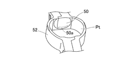
- this synthetic resin cage is a so-called corrugated cage, and concave spherical surfaces 50 are formed along the outer circumference of the ball at both circumferential ends of the inner surface of the pocket Pt. Patent Document 2).
- the load F of the belt that is, the radial load F
- the pulley (not shown) at the tip of the rotation shaft Sh is applied to the ball bearing that supports the rotation shaft Sh of the motor.
- retainer 52 revolves biased to one side.
- An object of the present invention is to provide a ball bearing cage capable of suppressing the entrainment of a lubricant in a pocket and reducing abnormal noise, and a ball bearing using the ball bearing cage. .
- the ball bearing retainer of the present invention is a ball guide for holding a ball in a plurality of portions in the circumferential direction of the annular portion around the bearing center axis in pockets provided through the annular portion in the radial direction.
- This is a ball bearing cage.
- the ball is located on either one of the radially outer diameter side portion or the radially inner diameter side portion of the inner surface of the pocket at the circumferentially opposed portions on both sides facing each other in the circumferential direction.
- a ball guide surface is provided as a guide.
- the ball guide surface has a cross-sectional shape that is inclined so as to approach the pocket center axis toward the tip, and is formed in a planar shape.
- the “planar shape” includes not only a flat surface but also a curved surface shape that slightly protrudes toward the inside of the pocket so as to be a point contact when the ball guide surface comes into contact with the ball.
- the ball guide surface located on the outer diameter side portion or the inner diameter side portion in the radial direction is provided in the circumferentially opposite portion of the inner surface of the pocket, and the ball guide surface has an inclined cross-sectional shape and is flat. It was in the shape. Therefore, during the bearing operation, the contact between the ball guide surface and the spherical ball is a point contact. Thereby, compared with the case of line contact, it becomes difficult to entrain the lubricant adhering to the ball into the pocket of the cage. Accordingly, drag resistance can be reduced.
- the lubricant even if the lubricant once enters the pocket while adhering to the ball, the lubricant does not stay in the pocket, and the annular gap extends over substantially the entire circumference other than the contact point between the ball guide surface and the ball. Then, it is smoothly discharged out of the pocket while being attached to the ball. Accordingly, drag resistance can be reduced. As a result, it is possible to prevent the ball revolution speed from changing instantaneously and the balance of the force in the radial direction applied from the ball to the cage from being lost. Therefore, the cage can be swung around, that is, vibration can be suppressed to reduce noise.
- the annular portion has two annular bodies facing each other in the axial direction of the annular portion, and a plurality of the pockets are formed by combining these annular bodies facing the axial direction.
- the cage can be easily assembled by combining two annular bodies from both sides in the axial direction. If this cage is made of resin and the two annular bodies have the same shape, the two annular bodies can be molded with one type of molding die. Therefore, the cost of the cage can be reduced by reducing the cost of the mold, and it is not necessary to separate the two annular bodies to be combined, and the management of the annular bodies is easy.
- the ball guide surface has a cross-sectional shape in which a cross section perpendicular to the bearing central axis protrudes in an arc shape toward the pocket central axis.
- the contact between the ball guide surface and the spherical ball is a point contact during the bearing operation.
- the ball guide surface has a cross-sectional shape in which a cross section perpendicular to the bearing central axis protrudes in an arc shape toward the pocket central axis and a partial cylindrical surface shape extending along the bearing axial direction, A shape that forms part of the cylindrical surface is preferred.
- the contact between the ball guide surface and the spherical ball is a point contact. Thereby, compared with the case of line contact, it becomes difficult to entrain the lubricant adhering to the ball into the pocket, so that drag resistance can be reduced.
- the ball guide surface has a partial cylindrical surface shape extending along the bearing axial direction, the molded product can be easily pulled out smoothly in the axial direction when this cage is molded with a mold.
- the shape of the pocket is deformed due to the influence of centrifugal force or heat, it is possible to ensure that the contact between the partially cylindrical surface of the ball guide surface extending along the bearing axial direction and the spherical ball is a point contact. Further, it is possible to make it difficult for the lubricant adhering to the ball to be caught in the pocket. Accordingly, drag resistance can be reduced more reliably.
- the spherical shell plate portion forming each pocket and the connecting portion that is a portion between adjacent pockets are alternately arranged in the circumferential direction, and at least the bearing axial direction in the connecting portion It is preferable that a flange projecting in the bearing axial direction is provided on the side surface facing. According to this configuration, it is possible to prevent the lubricant from entering the bearing raceway surface directly along the side surface of the cage in the bearing axial direction. In particular, when the flange is attached to the outer diameter side portion in the radial direction, the lubricant on the side surface of the cage is more reliably prevented from moving from the inner diameter side to the outer diameter side due to the centrifugal force during bearing operation.
- the lubricant can be prevented from excessively entering the outer ring raceway surface. Therefore, it is possible to prevent excessive lubricant from adhering to the ball and entering the pocket. Thereby, it becomes difficult to entrain the lubricant in the pocket of the cage.
- the ball when the annular portion is deformed by the centrifugal force during the bearing operation and the shape of the pocket is deformed, the ball contacts the convex portion of the axial guide surface.
- the ball When there is no convex part, when the shape of the pocket is deformed, the ball may excessively come into line contact with the axial guide surface.
- the convex portion is provided on the axial guide surface as described above, the ball can be brought into point contact with the convex portion of the axial guide surface without excessively contacting the ball with the axial guide surface. Therefore, it is possible to reliably prevent the ball bearing from generating abnormal heat and the cage from being worn by suppressing the contact surface pressure of the ball against the axial guide surface.
- the contact between the convex portion of the axial guide surface and the ball is a point contact, the lubricant attached to the ball is less likely to be caught in the pocket of the cage as compared with the case of the line contact. Accordingly, drag resistance can be reduced.
- the axial guide surfaces on both sides may be circular arc surfaces whose cross section perpendicular to the pocket central axis is an arc shape.
- the “arc surface” includes a cylindrical surface and a spherical surface.
- the ball bearing of the present invention is a ball bearing for a motor using the above-described ball bearing cage.
- the motor can be rotated at a higher speed. That is, noise from the ball bearing can be reduced even when the motor is rotated at a high speed.
- FIG. 9 is a sectional view taken along line IX-IX in FIG. 8.
- FIG. 9 is a sectional view taken along line XX in FIG. 8. It is sectional drawing of the annular body before assembling the ball bearing retainer. It is a perspective view of the principal part of the cage for ball bearings concerning a 3rd embodiment of this invention. It is the perspective view which looked at the principal part of the cage for ball bearings from the direction different from Drawing 11A. It is a top view of the cage for ball bearings. It is the XIII-XIII sectional view taken on the line of FIG. It is the figure which expanded the principal part of the cage for ball bearings concerning 4th Embodiment of this invention.
- FIG. 19 is a sectional view taken along line XIX-XIX in FIG. It is sectional drawing which shows the state which the ball guide surface of the ball bearing retainer and the ball contacted. It is a perspective view of the principal part of the cage for ball bearings concerning a 7th embodiment of this invention.
- FIG. 22 is a sectional view taken along line XXII-XXII in FIG. 21. It is a perspective view of the principal part of the cage for ball bearings concerning 8th Embodiment of this invention. It is a perspective view which shows the pocket of the conventional ball bearing cage. It is a figure explaining the state at the time of the belt load addition of the conventional ball bearing. It is a figure explaining the state which the retainer for ball bearings rotates in one direction. It is a figure explaining the state at the time of grease entrainment.
- the ball bearing retainer according to this embodiment is applied to, for example, a deep groove ball bearing retainer that rotatably supports a rotating shaft of a motor.
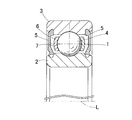
- FIG. 1 is a cross-sectional view of a ball bearing using a ball bearing cage 1 according to the first embodiment.
- This ball bearing is provided at both ends in the axial direction of the inner ring 2, the outer ring 3, a plurality of balls 4 interposed between the inner and outer rings 2, 3, the cage 1 that holds these balls 4, and the inner and outer rings 2, 3.
- the sealing members 5 and 5 are provided.
- the bearing space is sealed by the seal members 5 and 5, and grease is sealed in the bearing space.
- This cage 1 is a ball guide and is of an outer diameter restraint type.
- the ball guide is of a type that is supported by the inner ring 2 serving as the rotating side wheel via the ball 4 so that the cage 1 does not contact the inner and outer rings 2 and 3.
- the ball 4 is made of, for example, a steel ball or ceramics.
- the cage 1 has an annular portion 6 around the bearing center axis L and pockets 7 provided at a plurality of locations in the circumferential direction of the annular portion 6. Each pocket 7 is provided so as to penetrate the annular portion 6 in the radial direction. A ball 4 is held in the pocket 7.
- the cage 1 is made of resin, for example, and is manufactured by injection molding.
- a thermoplastic resin such as polyamide (PA), polyphenylene sulfide (PPS), polyether ether ketone (PEEK) is used.
- PA polyamide
- PPS polyphenylene sulfide
- PEEK polyether ether ketone
- glass fibers, carbon fibers, and aramid fibers are mixed in the resin applied to the cage 1 in order to increase the strength.
- retainer 1 is good also as the waveform holder
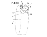
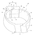
- FIG. 2A is a perspective view of a main part of the cage 1, and FIG. 2B is an enlarged view of the main part of FIG. 2A.
- the cage 1 is a so-called corrugated cage in which spherical shell-shaped plate portions 8 that form the pockets 7 and connecting portions 9 that are portions between adjacent pockets are alternately arranged in the circumferential direction.
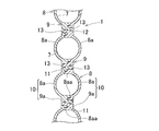
- the annular portion 6 of the cage 1 has two annular bodies 10, 10 facing each other in the axial direction of the annular portion 6, and these annular bodies 10, 10 are axially arranged.
- a plurality of pockets 7 are formed in combination facing each other.
- the two annular bodies 10, 10 of this embodiment have the same shape, and are combined in opposite directions.
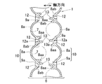
- FIG. 4A is a plan view of a part of the cage 1 as seen from the outer diameter side
- FIG. 4B is an enlarged view of a part of FIG. 4A.
- Each annular body 10 includes a spherical shell-shaped plate half 8a that forms a hemispherical pocket 7, and a connecting half 9a that is a portion between adjacent hemispherical pockets.
- a spherical shell-shaped plate portion 8 is formed by combining two spherical shell-shaped plate portion halves 8a, 8a facing each other.
- the connecting portion 9 is formed by combining the two connecting portion halves 9a, 9a facing each other.
- the connecting portion 9 has a mating surface 11 that comes into surface contact when the two connecting portion halves 9a and 9a are combined.
- the mating surface 11 is a plane perpendicular to the axial direction.
- engaging holes 12 penetrating both side surfaces are formed.
- An engaging claw 13 that is inserted into and engaged with an engaging hole 12 formed in the other connecting part half 9a is formed in one connecting part half 9a.
- An engagement step portion 12 a is provided in the engagement hole 12.
- a hook portion 13 a that engages with the engagement step portion 12 a of the engagement hole 12 is formed at the distal end portion of the engagement claw 13.
- the two annular bodies 10 and 10 are made to face each other in the axial direction, and the respective engaging claws 13 of one connecting portion half 9a are inserted into the respective engaging holes 12 of the corresponding other connecting portion half 9a. Further, by engaging the flange portion 13a of each engagement claw 13 with the engagement step portion 12a of each engagement hole 12, a waveform holder in which the two annular bodies 10, 10 are coupled to each other is obtained.
- Each spherical shell-like plate half 8a is provided with a protruding wall 8aa protruding in the axial direction.
- a protruding wall 8aa protruding in the axial direction toward the one spherical shell plate half.
- the protruding wall portion 8aa of the one spherical shell plate half body 8a is formed at one end in the circumferential direction of the other spherical shell plate half body 8a.
- a fitting recess 8ab into which is fitted is provided.
- a fitting recess 8ab into which the protruding wall 8aa of the other spherical shell plate half 8a is fitted is provided at the other circumferential end of the one spherical shell plate half 8a.
- a minute gap is formed between the tip surface of the protruding wall 8aa and the bottom surface of the fitting recess 8ab facing the tip surface.
- the front end surface of the protruding wall portion 8aa and the bottom surface of the fitting recess 8ab are formed at positions shifted from the axial center of the pocket 7 in the axial direction.
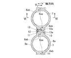
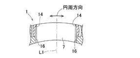
- FIG. 5A is a cross-sectional view taken along the line VV of FIG. 4B
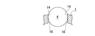
- FIG. 5B is a cross-sectional view showing a state where the ball guide surface of the cage 1 and the ball are in contact with each other
- 6A is a cross-sectional view taken along line VI-VI in FIG. 4B
- FIG. 6B is a cross-sectional view of each annular body 10 before assembly of the cage.
- the inner surface of each pocket 7 is located on the circumferentially opposed portion on both sides facing each other in the circumferential direction, on the radially outer diameter side portion.
- Ball guide surfaces 14, 14 are provided.
- the ball guide surface 14 is formed in a cross-sectional shape (tapered shape) that is inclined so as to approach the pocket central axis L1 toward the tip, and is formed in a planar shape.
- the cage 1 is configured as a ball guide with an outer diameter restraint type.
- axial guide surfaces 15, 15 are formed on both sides of the pocket 7 facing each other in the bearing axial direction.
- the axial guide surface 15 is configured by an arc surface whose cross section perpendicular to the pocket central axis L1 is an arc shape.
- the “arc surface” may be either a cylindrical surface or a spherical surface.
- the above-described “planar shape” includes not only a flat surface but also a curved surface shape that slightly protrudes toward the pocket side when the ball guide surface 14 comes into contact with the ball 4 (FIG. 5B).
- the spherical shell-like plate portion 8 is a groove-like shape between the corresponding protruding wall portion 8aa and the bottom of the fitting concave portion 8ab in a state where the two spherical shell-like plate half halves 8a and 8a are assembled.
- a gap ⁇ is formed.
- the groove-like gap ⁇ 1 in the ball guide surface 14 is formed at a position shifted in the axial direction from the central portion of the pocket 7 in the axial direction.
- the gap ⁇ 1 extends in a direction perpendicular to the bearing axial direction, and communicates with a groove-like gap ⁇ 2 in the opposing plane 16 described later.
- the portions other than the ball guide surface 14 in the circumferentially opposite portions on both sides of each pocket 7 have a planar shape parallel to a plane including the pocket central axis L1 and the bearing axial direction. These portions having a planar shape constitute the opposing plane 16.
- the base ends of the ball guide surfaces 14 are connected to the opposing plane 16 at the circumferentially opposing portions on both sides.
- the opposing plane 16 is formed at a position recessed in the pocket diameter increasing direction from both side edges 15a of the arcs in the adjacent axial guide surfaces 15.
- both side edges 15 a of arcs of adjacent axial guide surfaces 15 are connected.
- the gap ⁇ 2 extending from the radially outer diameter side portion to the vicinity of the center on the opposing plane 16 is also formed at a position shifted in the axial direction from the axial center of the pocket 7.
- This gap ⁇ 2 extends in a direction perpendicular to the bearing axial direction.
- the axial position of the gap ⁇ 2 is connected at the same axial position as the gap ⁇ 1 on the ball guide surface 14.
- the gap ⁇ 3 in the radially inner diameter side portion of the opposing plane 16 is formed at a substantially axial center position of the pocket 7.
- the gap ⁇ 3 in the radially inner side portion and the gap ⁇ 2 near the center in the radial direction communicate with each other via a gap ⁇ 4 extending in the bearing axial direction.
- Test conditions and test results The ball bearing provided with the cage described above was incorporated into a testing machine, and a test was performed to determine whether abnormal noise was generated in the cage.
- the test conditions are as follows. ⁇ Test conditions> Test machine: Servo motor Belt load: 3400N Rotation speed: 1000min -1 ⁇ 7000min -1 ⁇ 3000min -1 ⁇ 7000min -1 However, 7000Min -1 from 1000min -1, or to step up every 1000min -1 when increasing the rotation speed from 3000 min -1 to 7000Min -1, when decreasing the rotational speed from 7000Min -1 to 3000 min -1 1000min -1 Step down every time.
- Judgment method Auditory judgment
- the ball guide surface 14 is provided on the radially outer diameter side portion of the inner surface of the pocket 7 in the circumferentially opposed portion, and the ball guide surface 14 has an inclined cross-sectional shape, and It is formed in a planar shape. Therefore, during the bearing operation, the contact between the ball guide surface 14 and the ball 4 is a point contact. Thereby, compared with the case of a line contact, it becomes difficult to entrain the grease adhering to the ball 4 in the pocket of the cage 1. Accordingly, drag resistance can be reduced.
- the axial guide surfaces 15 on both sides of the pocket 7 are arc surfaces whose cross section perpendicular to the pocket center axis L1 is an arc shape. Therefore, for example, when the cage 1 is elastically deformed using the cage 1 in a high-speed rotation region, the contact surface pressure between the axial guide surfaces 15 on both sides of the pocket 7 and the ball 4 greatly varies. Can be prevented. As a result, abnormal heat generation of the ball bearing and wear of the cage 1 can be prevented. Further, the grease is prevented from staying on the axial guide surface 15 of the pocket 7, and the drag resistance can be further reduced.
- the high-speed rotation range is 5000 min ⁇ 1 or more, but is not limited to this rotation speed.
- the annular portion 6 is configured by combining two annular bodies 10 and 10 facing each other in the axial direction so as to face each other in the axial direction, and a plurality of pockets 7 are formed. Therefore, after inserting the plurality of balls 4 between the raceway surfaces of the inner and outer rings 2 and 3, the two annular bodies 10 and 10 can be combined from both sides in the axial direction to easily assemble the cage 1.
- the cage 1 is made of resin and the two annular bodies 10 and 10 have the same shape, the two annular bodies 10 and 10 can be molded with one type of molding die. For this reason, it is possible to reduce the cost of the cage 1 while suppressing the cost of the mold, and it is not necessary to separate the two annular bodies 10 and 10 to be combined, and the management of the annular body 10 is easy.
- the motor can be rotated at a higher speed. That is, noise from the ball bearing can be reduced even when the motor is rotated at a high speed.
- FIG. 7 is a perspective view of the main part of the ball bearing retainer 1A according to the second embodiment
- FIG. 8 is a plan view of the main part of the ball bearing retainer 1A viewed from the outer diameter side.
- 9A is a cross-sectional view taken along the line IX-IX in FIG. 8, and FIG. 9B is a cross-sectional view showing a state where the ball guide surface and the ball are in contact with each other.
- 10A is a cross-sectional view taken along line XX of FIG. 8, and FIG. 10B is a cross-sectional view of each annular body 10 before assembly of the cage.
- the cage 1A is a ball guide and has an inner diameter restraint type.
- a ball guide surface 14 is provided on a radially inner side portion of the inner surface of the pocket 7 at a circumferentially opposed portion, and the ball guide surface 14 has an inclined cross-sectional shape and a planar shape. Is formed.
- the gap ⁇ 1 between the protruding wall portion 8aa and the fitting recess 8ab on the ball guide surface 14 is formed at a position shifted in the axial direction from the axial center of the pocket 7.
- the gap ⁇ 1 extends in a direction perpendicular to the bearing axial direction and communicates with the gap ⁇ 2 of the opposing plane 16.
- a gap ⁇ ⁇ b> 2 extending inward and outward in the radial direction on the opposing plane 16 is also formed at a position shifted in the axial direction from the axial center of the pocket 7.
- the ball guide surface 14 is provided on the radially inner side portion of the inner surface of the pocket 7 at the circumferentially opposed portion, and the ball guide surface 14 has a slanted cross-sectional shape and a planar shape. Is formed. Therefore, during the bearing operation, the contact between the ball guide surface 14 and the ball 4 is a point contact (FIG. 9B). Thereby, compared with the case of a line contact, it becomes difficult to entrain the grease adhering to the ball
- 11A and 11B are perspective views of main parts of a ball bearing retainer 1B according to the third embodiment. 11A and 11B are perspective views of the ball bearing cage 1B as seen from different directions. 12 is a plan view of the ball bearing retainer 1B, and FIG. 13 is a cross-sectional view taken along line XIII-XIII in FIG.
- this cage 1B is provided with convex portions 17 on the axial guide surfaces 15 and 15 on both sides of each pocket 7, respectively.
- the radially outer diameter side portion 15b of the axial guide surface 15 is formed in a conical surface.
- the radially outer diameter side portion 15b of the axial guide surface 15 is provided with an axial ball guide surface formed in a cross-sectional shape that is inclined so as to approach the pocket center axis toward the tip.
- the cross section perpendicular to the pocket center axis L1 is formed by an arc surface 15c having an arc shape.
- a convex portion 17 is provided on each arc surface 15c.
- the convex portion 17 is provided on the axial guide surfaces 15 on both sides in the vicinity of the axis L2 around which the ball rotates in the pocket, and is formed like a boss portion protruding in a hemispherical shape on the pocket side.
- the diameter and protrusion amount of the protrusion 17 are determined to be several percent of the ball diameter based on the results of tests, simulations, and the like. However, it is not limited to the value of this embodiment.
- the convex portion 17 suppresses an increase in the contact range between the annular portion 6 and the ball 4 when the annular portion 6 is deformed by the centrifugal force during the bearing operation and the shape of the pocket 7 is deformed.
- one protrusion 17 is provided on each axial guide surface 15, but a plurality of protrusions 17 may be provided.
- the cage 1B is provided with a flange 18 that prevents grease from entering the inner and outer ring raceway surfaces directly along the bearing axial direction side surface of the cage 1B.
- a flange 18 projecting in the bearing axial direction is formed on the radially outer diameter side portion of the side surface facing the bearing axial direction in the connecting portion 9 and the side surface facing the bearing axial direction in the spherical shell plate portion 8. Is provided.
- the flanges 18 are provided on both sides in the bearing axial direction.
- the width dimension of the cage 1B including both side flanges 18 and 18 in the connecting portion 9 and the width dimension of the cage 1B including both side flanges 18 and 18 in the spherical shell plate portion 8 are the same.
- the one axial flange 18 in the connecting portion 9 and the one axial flange 18 in the spherical shell-shaped plate portion 8 are formed to have the same axial tip position. The same applies to the other flange 18 in the axial direction.
- the spherical shell-shaped plate portion 8 is provided with an inner flange 19 that prevents the grease from entering the pocket 7.
- an inner flange 19 projecting inward of the pocket is provided on the radially inner diameter side edge portions on both sides facing each other in the circumferential direction among the inner surfaces of the pocket 7 in the spherical shell-shaped plate portion 8.
- the inner flange 19 is formed in an arc shape in plan view (FIG. 12). The reason why the inner flanges 19 are hardly provided on the axial guide surfaces 15 on both sides is as follows.
- the cage 1B when the annular portion 6 is deformed by the centrifugal force during the bearing operation and the shape of the pocket 7 is deformed, the ball is brought into contact with the convex portion 17 of the axial guide surface 15.
- a conical ball guide surface is provided on the radially outer portion 15 b of the axial guide surface 15. Therefore, when there is no convex part 17, when the shape of the pocket 7 elastically deforms, it is possible that a ball
- the convex portion 17 is provided on the axial guide surface 15 as described above, the ball does not come into line contact with the conical ball guide surface, and the ball is placed on the convex portion 17 of the axial guide surface 15. Point contact can be made. Therefore, it is possible to reliably prevent the ball bearing from generating abnormal heat and wear the retainer 1B by suppressing the contact surface pressure of the ball against the axial guide surface 15. Further, the contact between the convex portion 17 of the axial guide surface 15 and the spherical ball is a point contact, so that the grease attached to the ball is less likely to be caught in the pocket of the cage 1B as compared with the case of the line contact. . Accordingly, drag resistance can be reduced.
- the convex portions 17 are provided in the axial guide surfaces 15 and 15 on both sides in the vicinity of the axis L2 around which the ball rotates, the ball can be rotated and revolved stably. Thereby, the whirling of the cage 1B can be more reliably suppressed.
- the flange 18 projecting in the bearing axial direction is provided on the side surface of the connecting portion, it is possible to prevent grease from entering the inner and outer ring raceway surfaces directly along the bearing axial direction side surface of the cage 1B.
- the flange 18 is attached to the outer diameter side portion in the radial direction, the grease on the side surface of the cage is more reliably prevented from moving from the inner diameter side in the radial direction to the outer diameter side due to centrifugal force during bearing operation.
- FIG. 14 is a perspective view of a main part of a ball bearing cage 1C according to the fourth embodiment
- FIG. 15 is a cross-sectional view showing a state where the ball guide surface and the ball are in contact with each other.
- the ball guide surface 14 has a cross-sectional shape in which a cross section perpendicular to the bearing central axis L protrudes in an arc shape toward the pocket central axis L1 and a partial cylindrical surface extending along the bearing axial direction. It is formed in a shape (a so-called saddle shape). Due to the ball guide surface 14, the cage 1 is configured as a ball guide with an outer diameter restraint type. Other configurations are the same as those of the first embodiment.
- the ball guide surface 14 has a cross-sectional shape in which a cross section perpendicular to the bearing central axis L protrudes in an arc shape toward the pocket central axis L1
- the ball guiding surface can be used during bearing operation.
- the contact between 14 and the spherical ball 4 is a point contact.
- the ball guide surface 14 has a cross-sectional shape in which a cross section perpendicular to the bearing central axis L protrudes in an arc shape toward the pocket central axis L1, and a partial cylindrical surface extending along the bearing axial direction.
- the annular body 10 that is a molded product can be easily pulled out smoothly in the axial direction.
- the contact between the ball guide surface 14 having a partial cylindrical surface extending along the bearing axial direction and the spherical ball 4 is reliably point contact. By doing so, it is possible to make it difficult for the lubricant adhering to the ball 4 to be caught in the pocket 7. Therefore, drag resistance can be reduced more reliably.
- FIG. 16 is a perspective view of a main part of a ball bearing cage 1Aa according to the fifth embodiment.
- this cage 1Aa with respect to the cage 1A of the second embodiment of FIG. 7, the ball guide surface 14 located in the circumferentially opposite portion of the inner surface of the pocket 7 projects in an arc shape only at the center in the bearing axial direction. It becomes the shape to do.
- Other configurations are the same as those of the cage 1A of the second embodiment in FIG.
- the cage 1Aa of the fifth embodiment also has the same effect as the cage 1A of the second embodiment.
- FIG. 17 is a perspective view of a main part of a ball bearing cage 1D according to the sixth embodiment
- FIG. 18 is a plan view of the main part of the ball bearing cage 1D as viewed from the outer diameter side.
- 19A is a cross-sectional view taken along line XIX-XIX in FIG.
- the cage 1D of the sixth embodiment is a ball guide and is an inner diameter restraint type.
- Convex portions 17 are provided on the axial guide surfaces 15 and 15 on both sides of each pocket 7 in the cage 1D.
- a ball guide surface 14 located on the inner diameter side portion in the radial direction is provided in a circumferentially opposed portion of the inner surface of the pocket 7.
- the ball guide surface 14 has a cross-sectional shape in which a cross section perpendicular to the bearing central axis L (FIG. 1) protrudes in an arc shape toward the pocket central axis L1 and a partial cylindrical surface shape extending along the bearing axial direction. Yes.
- the ball guide surface 14 located on the inner diameter side portion in the radial direction is provided in the circumferentially opposed portion of the inner surface of the pocket 7, and this ball guide surface 14 is provided with the bearing center axis L.
- the cross section perpendicular to is a cross-sectional shape that protrudes in an arc shape toward the pocket center axis L1 and has a partial cylindrical surface shape that extends along the bearing axis direction. Therefore, during the bearing operation, the contact between the ball guide surface 14 and the spherical ball 4 is a point contact (FIG. 19B). Thereby, compared with the case of a line contact, the grease adhering to the ball
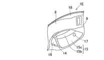
- 20A and 20B are perspective views of main parts of a ball bearing retainer 1E according to the seventh embodiment.
- 20A and 20B are perspective views of the ball bearing cage 1E as seen from different directions.
- 21 is a plan view of the ball bearing retainer 1E
- FIG. 22 is a sectional view taken along line XXII-XXII in FIG.
- convex portions 17 are provided on the axial guide surfaces 15 and 15 on both sides of each pocket.
- the outer diameter side portion 15b in the radial direction of the axial guide surface 15 is formed in a conical surface. That is, the radially outer diameter side portion 15b of the axial guide surface 15 forms an axial ball guide surface, and the ball guide surface is inclined so as to approach the pocket central axis toward the tip. It is formed into a shape.
- the surface of the axial guide surface 15 other than the outer diameter side portion 15b is formed by an arcuate surface 15c whose cross section perpendicular to the pocket central axis L1 is arcuate.
- a convex portion 17 is provided on each arc surface 15c.
- the cage 1E of the seventh embodiment has a flange 18 that prevents grease from entering the inner and outer ring raceway surfaces directly along the bearing axial direction side surface of the cage 1E.
- a flange 18 projecting in the bearing axial direction is formed on the radially outer diameter side portion of the side surface facing the bearing axial direction in the connecting portion 9 and the side surface facing the bearing axial direction in the spherical shell plate portion 8. Is provided.
- the flanges 18 are provided on both sides in the bearing axial direction.
- FIG. 23 is a perspective view of a main part of a ball bearing cage 1Da according to the eighth embodiment.
- the cage 1Da according to the eighth embodiment is different from the cage 1D according to the sixth embodiment in FIG. 17 in that the ball guide surface 14 located at the circumferentially opposed portion of the inner surface of the pocket 7 is only at the center in the bearing axial direction. It has a shape protruding in an arc shape.
- Other configurations are the same as those of the cage 1D of the sixth embodiment in FIG.
- the ball guide surface 14 has a cross-sectional shape in which a cross section perpendicular to the bearing central axis L (FIG. 19A) protrudes in an arc shape toward the pocket central axis.
- Contact between the ball guide surface 14 and the spherical ball 4 (FIG. 1) is point contact.
- the cage is not limited to resin but may be made of metal.
- brass may be formed by machining.
- the cage may not be a mating cage composed of two annular bodies.
- the place where the flange is provided is not limited to the outer diameter side portion in the radial direction.
- a flange projecting in the bearing axial direction may be provided on a radially inner side portion or a portion near the center in the radial direction among the side surfaces of the connecting portion or the like.
- Lubricating oil may be applied as a lubricant instead of grease.
- a lubricating oil having a viscosity of VG32 or higher can be considered.
- An angular ball bearing may be applied as a ball bearing using each cage.
- the ball bearings of the above embodiments are of the double-sided seal type, but a seal may be provided only on one side, or a so-called open type without both seals. These ball bearings can also be applied to uses other than motors. Also in this case, noise from the ball bearing can be reduced.
- a ball bearing retainer is a ball that holds balls in pockets provided in a plurality of locations in the circumferential direction of the annular portion around the center axis of the bearing so as to penetrate the annular portion in the radial direction.
- a guide ball bearing cage The ball is located on either one of the radially outer diameter side portion or the radially inner diameter side portion of the inner surface of the pocket at the circumferentially opposed portions on both sides facing each other in the circumferential direction.
- a ball guide surface is provided as a guide, The ball guide surface is formed in a cross-sectional shape that is inclined so as to approach the pocket central axis toward the tip, and has a planar shape.
- the axial guide surfaces on both sides facing each other in the bearing axis direction of the pocket are arc surfaces whose cross section perpendicular to the pocket central axis is an arc shape.
- the ball bearing retainer according to aspect 2 is the ball bearing retainer according to aspect 1, wherein the annular portion includes two annular bodies facing each other in the axial direction of the annular portion. A plurality of the pockets are formed by combining bodies in opposition to the axial direction.
- a ball bearing retainer is a ball that holds a ball in a plurality of portions in the circumferential direction of the annular portion around the center axis of the bearing and in a pocket provided through the annular portion in the radial direction.
- a guide ball bearing cage The ball is located on either one of the radially outer diameter side portion or the radially inner diameter side portion of the inner surface of the pocket at the circumferentially opposed portions on both sides facing each other in the circumferential direction.
- a ball guide surface is provided as a guide, The ball guide surface has a cross-sectional shape in which a cross section perpendicular to the bearing central axis protrudes in an arc shape toward the pocket central axis.
- a ball bearing retainer according to aspect 5 is the ball bearing retainer according to aspect 4, wherein the ball guide surface has a cross-sectional shape in which a cross section perpendicular to the bearing central axis protrudes in an arc shape toward the pocket central axis. And it is set as the shape of the partial cylindrical surface shape extended along a bearing axial direction.
- the ball bearing retainer according to aspect 6 is the ball bearing retainer according to aspect 4 or aspect 5, wherein the spherical shell plate portion that forms each of the pockets, and a connecting portion that is a portion between adjacent pockets, Is a waveform holder alternately arranged in the circumferential direction, A flange projecting in the bearing axial direction is provided on at least a side surface of the coupling portion facing the bearing axial direction.
- the ball bearing for a motor according to aspect 7 uses the ball bearing retainer according to any one of aspects 4 to 6.
- a ball bearing retainer is a ball that holds balls in pockets provided in a plurality of locations in the circumferential direction of the annular portion around the center axis of the bearing and extending radially through the annular portion.
- a guide ball bearing cage When the annular portion is deformed by centrifugal force and the shape of the pocket is deformed on both axial guide surfaces facing each other in the bearing axial direction of the pocket, the annular portion comes into contact with the ball. Protrusions that suppress an increase in the contact range with the ball are provided.
- the ball bearing retainer according to aspect 9 is the ball bearing retainer according to aspect 8, wherein the spherical shell plate portion that forms each pocket and the connecting portion that is a portion between adjacent pockets are circumferential. Waveform holders arranged alternately in the direction A flange projecting in the bearing axial direction is provided on at least a side surface of the coupling portion facing the bearing axial direction.
- the ball bearing cage according to Aspect 10 is the ball bearing cage according to Aspect 8 or Aspect 9, wherein the annular portion has two annular bodies facing each other in the axial direction of the annular portion. A plurality of the pockets are formed by combining these annular bodies facing each other in the axial direction.
- the ball bearing retainer according to aspect 11 is the ball bearing retainer according to any one of aspects 8 to 10, in the circumferential direction on both sides of the inner surface of the pocket facing each other in the circumferential direction.
- the opposing portion is provided with a ball guide surface serving as the ball guide, located on either the outer diameter side portion in the radial direction or the inner diameter side portion in the radial direction,
- the ball guide surface is formed in a cross-sectional shape that is inclined so as to approach the pocket central axis toward the tip, and has a planar shape.
- the axial guide surfaces on both sides are arc surfaces whose cross section perpendicular to the pocket central axis is an arc shape.
- the ball bearing retainer according to aspect 12 is the ball bearing retainer according to any one of aspects 8 to 10, in the circumferential direction on both sides of the inner surface of the pocket facing each other in the circumferential direction.
- the opposing portion is provided with a ball guide surface serving as the ball guide, located on either the outer diameter side portion in the radial direction or the inner diameter side portion in the radial direction,
- the ball guide surface has a cross-sectional shape in which a cross section perpendicular to the bearing central axis protrudes in an arc shape toward the pocket central axis.
- the ball bearing retainer according to aspect 13 is the ball bearing retainer according to aspect 12, wherein the ball guide surface has a cross-sectional shape in which a cross section perpendicular to the bearing central axis protrudes in an arc shape toward the pocket central axis. And it is set as the shape of the partial cylindrical surface shape extended along a bearing axial direction.
- the ball bearing for a motor according to the fourteenth aspect uses the ball bearing retainer according to any one of the eighth to thirteenth aspects.
- a ball bearing retainer is a ball that holds a ball in a plurality of portions in the circumferential direction of the annular portion around the center axis of the bearing in a pocket provided through the annular portion in the radial direction.
- This is a ball bearing cage for guide ball bearings, in which the spherical shell plate portion forming each pocket and the connecting portion serving as a portion between adjacent pockets are alternately arranged in the circumferential direction.
- a flange projecting in the bearing axial direction is provided on at least a side surface of the coupling portion facing the bearing axial direction.
- the corrugated cage for ball bearings according to aspect 16 is the corrugated cage for ball bearings according to aspect 15, wherein the annular portion has two annular bodies facing each other in the axial direction of the annular portion, A plurality of the pockets are formed by combining these annular bodies facing each other in the axial direction.
- a ball bearing for a motor according to Aspect 17 uses the ball bearing corrugated cage according to Aspect 15 or Aspect 16.
Landscapes
- Engineering & Computer Science (AREA)
- General Engineering & Computer Science (AREA)
- Mechanical Engineering (AREA)
- Rolling Contact Bearings (AREA)
Abstract
玉軸受用保持器における軸受中心軸回りの円環部(6)の円周方向の複数箇所に、この円環部(6)を半径方向に貫通してポケット(7)が設けられている。このポケット(7)内にボールが保持され、案内されている。ポケット(7)の内面のうち円周方向に互いに対向する両側の円周方向対向部分に、半径方向の外径側部分に位置してボールを案内するボール案内面(14,14)が設けられている。ボール案内面(14)は、先端に向かうに従ってポケット中心軸に近づくように傾斜する断面形状で、且つ、平面状に形成されている。
Description
この出願は、2015年1月29日出願の特願2015-015199、特願2015-015425、2015年2月4日出願の特願2015-019837、2015年2月16日出願の特願2015-027165、2016年1月12日出願の特願2016-003300、2016年1月12日出願の特願2016-003301および2016年1月12日出願の特願2016-003302の優先権を主張するものであり、その全体を参照により本願の一部をなすものとして引用する。
この発明は、玉軸受用保持器およびその玉軸受用保持器を用いた玉軸受に関し、例えば、モータ用の玉軸受における保持器音を低減する技術に関する。
従来、例えばモータ用の玉軸受において、合成樹脂製の保持器を採用したものが提案されている(例えば特許文献1,2)。この合成樹脂製の保持器は、図24に示すように、いわゆる波形保持器であって、ポケットPtの内面の周方向両端部に、ボールの外周に沿った凹球面50が形成されている(特許文献2)。
図24の保持器52では、軸受運転時に、この保持器52が径方向に移動すると、凹球面50におけるポケット内径部50aが線接触となる。そのため、ボールに付着したグリースが保持器52のポケット内に巻き込まれて引き摺り抵抗が大きくなっていた。これにより保持器52に異音が発生していた。
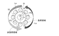
つまり、図25に示すように、モータの回転軸Shを支持する玉軸受に、回転軸Shの先端のプーリ(図示せず)に掛装されたベルトの荷重F(すなわちラジアル荷重F)が負荷されている場合を考える。この場合、ポケット内へのグリースの巻き込みにより、図25の状態のボール51から保持器52へ加わる径方向内外の力Faが増加される。これにより、図26に示すように、保持器52が一方に偏って公転する。
この状態でさらにポケット内にグリースが巻き込まれると、図27に示すように、瞬間的にボール公転速度の変化やボール51から保持器52へ加わる径方向内外の力Faのバランスが崩れ、保持器52が振れ廻る。なお図25~図27の符号A1は、この玉軸受つまり保持器52の回転方向を示す。図25~図27の円弧Laは回転時のボールと保持器ポケットの接触位置を示す。図26、図27では保持器52の偏りを実際よりも強調して示している。
玉軸受にベルト荷重によるラジアル荷重が付加されていない場合も、ポケット内にグリースが巻き込まれることで、瞬間的にボール公転速度の変化やボール51から保持器52へ加わる径方向内外の力のバランスが崩れ、保持器52が振れ廻っているものと考えられる。上記の状態になると、図24に示すように、ボールが保持器のポケット内径部50aで積極的に案内され、ボールと保持器ポケット間のグリース厚みの変動で保持器52が振動し異音が発生しているものと考えられる。
この発明の目的は、ポケット内への潤滑剤の巻き込みを抑制し、異音の低減を図ることができる玉軸受用保持器およびその玉軸受用保持器を用いた玉軸受を提供することである。
この発明の玉軸受用保持器は、軸受中心軸回りの円環部の円周方向の複数箇所に、この円環部を半径方向に貫通して設けられたポケット内にボールを保持するボール案内の玉軸受用保持器である。前記ポケットの内面のうち前記円周方向に互いに対向する両側の円周方向対向部分に、前記半径方向の外径側部分または前記半径方向の内径側部分のいずれか一方に位置して、前記ボール案内とするボール案内面が設けられている。このボール案内面は、先端に向かうに従ってポケット中心軸に近づくように傾斜する断面形状で、且つ、平面状に形成されている。ここで、「平面状」とは、平面だけでなく、ボール案内面がボールと接触したとき点接触となるようなポケット内部側に僅かに突出する曲面形状も含む。
この構成によると、ポケットの内面の円周方向対向部分に半径方向の外径側部分または内径側部分に位置するボール案内面を設け、このボール案内面を、傾斜する断面形状で、且つ、平面状とした。そのため、軸受運転時、ボール案内面と球形のボールとの接触は点接触となる。これにより、線接触の場合と比べて、ボールに付着した潤滑剤を保持器のポケット内に巻き込み難くなる。したがって引き摺り抵抗の低減を図ることができる。
換言すれば、潤滑剤がボールに付着したままポケット内に一旦侵入しても、この潤滑剤は、ポケット内に滞留することなく、ボール案内面とボールの接触点以外の略全周にわたる環状隙間から、ボールに付着した状態のままポケット外に円滑に排出される。したがって、引き摺り抵抗の低減を図ることができる。これにより、瞬間的にボール公転速度が変化すること、および、ボールから保持器へ加わる径方向内外の力のバランスが崩れることを防止できる。したがって、保持器が振れ廻ること、すなわち振動を抑制して、異音の低減を図ることができる。
この発明において、前記円環部は、この円環部の軸方向に互いに対向する二つの環状体を有し、これら環状体を前記軸方向に対向して組み合わせて複数の前記ポケットが形成されていることが好ましい。この構成によれば、内外輪の軌道面間に複数のボールを挿入した後、二つの環状体を前記軸方向の両側から組み合わせてこの保持器を容易に組み立てることができる。この保持器を樹脂製として二つの環状体を同一形状とすると、一種類の成形用金型で前記二つの環状体を成形できる。そのため、金型費用を抑えて保持器のコスト低減を図れると共に、組み合わせる二つの環状体を分別する必要がなく環状体の管理も容易である。
この発明において、前記ボール案内面は、前記軸受中心軸に垂直な断面がポケット中心軸側に円弧状に突出する断面形状とされていることが好ましい。この構成によると、軸受運転時、ボール案内面と球形のボールとの接触は点接触となる。これにより、線接触の場合と比べて、ボールに付着した潤滑剤を保持器のポケット内に巻き込み難くなる。したがって引き摺り抵抗の低減を図ることができる。
この発明において、前記ボール案内面は、前記軸受中心軸に垂直な断面がポケット中心軸側に円弧状に突出する断面形状で、且つ、軸受軸方向に沿って延びる部分円柱面状の形状、つまり円柱面の一部を形成する形状であることが好ましい。この構成によれば、ボール案内面が円弧状に突出する断面形状であるので、ボール案内面と球形のボールとの接触は点接触となる。これにより、線接触の場合と比べて、ボールに付着した潤滑剤をポケット内に巻き込み難くなることで、引き摺り抵抗の低減を図れる。
さらに、ボール案内面が、軸受軸方向に沿って延びる部分円柱面状の形状であるので、この保持器を金型で成形した場合に成形品を軸方向に円滑に抜き易くすることができる。また、遠心力や熱の影響によりポケットの形状が変形した場合でも、軸受軸方向に沿って延びる部分円柱面状のボール案内面と、球形のボールとの接触を確実に点接触とすることで、ボールに付着した潤滑剤をポケット内に巻き込み難くすることができる。したがって引き摺り抵抗の低減をより確実に図れる。
この発明において、前記各ポケットを形成する球殻状板部と、隣り合うポケット間の部分となる連結部とが円周方向に交互に並ぶ波形保持器であり、少なくとも前記連結部における軸受軸方向を向く側面に、前記軸受軸方向に突出するフランジが設けられていることが好ましい。この構成によれば、潤滑剤が保持器の軸受軸方向の側面を伝わって直接軸受軌道面に入ることを防止できる。特に、フランジを半径方向の外径側部分に付設した場合には、軸受運転時の遠心力により保持器側面の潤滑剤が半径方向の内径側から外径側に移動することをより確実に抑制し、潤滑剤が外輪軌道面に過剰に侵入することを防止できる。したがって、過剰な潤滑剤がボールに付着してポケット内に侵入することを未然に防止することができる。これにより、潤滑剤を保持器のポケット内により巻き込み難くなる。
この発明において、前記ポケットの軸受軸方向に互いに対向する両側の軸方向案内面に、遠心力で前記円環部が変形して前記ポケットの形状が変形したときに、前記ボールと当接して前記円環部と前記ボールとの接触範囲の増大を抑制する凸部が設けられていることが好ましい。
この構成によると、軸受運転時に遠心力で円環部が変形してポケットの形状が変形したときに、軸方向案内面の凸部にボールが接触する。凸部がない場合、ポケットの形状が変形したときに、軸方向案内面にボールが過度に線接触する可能性がある。しかしながら、前述のように軸方向案内面に凸部を設けたので、軸方向案内面にボールが過度に線接触することなく、軸方向案内面の凸部にボールを点接触させることができる。したがって、軸方向案内面に対するボールの接触面圧を抑えて玉軸受が異常発熱すること、および保持器が摩耗することを確実に防止できる。また、軸方向案内面の凸部とボールとの接触は点接触となることにより、線接触の場合と比べて、ボールに付着した潤滑剤を保持器のポケット内に巻き込み難くなる。したがって引き摺り抵抗の低減を図ることができる。
前記凸部が設けられている場合、前記両側の軸方向案内面は、前記ポケット中心軸に垂直な断面が円弧状となる円弧面であっても良い。ここで、「円弧面」は、円筒面および球面を含む。
この発明の玉軸受は、上述の玉軸受用保持器を用いたモータ用の玉軸受である。この場合、モータの高速回転化をより図ることができる。つまり、モータを高速回転させても玉軸受からの異音を低減できる。
請求の範囲および/または明細書および/または図面に開示された少なくとも2つの構成のどのような組合せも、この発明に含まれる。特に、請求の範囲の各請求項の2つ以上のどのような組合せも、この発明に含まれる。
この発明は、添付の図面を参考にした以下の好適な実施形態の説明からより明瞭に理解されるであろう。しかしながら、実施形態および図面は単なる図示および説明のためのものであり、この発明の範囲を定めるために利用されるべきものではない。この発明の範囲は添付の請求の範囲によって定まる。添付図面において、複数の図面における同一の部品番号は、同一または相当部分を示す。
この発明の第1実施形態に係る玉軸受用保持器を用いた玉軸受の断面図である。
同玉軸受用保持器の要部の斜視図である。
同玉軸受用保持器の要部を拡大した図である。
同玉軸受用保持器の二つの環状体を結合する前の状態を示す断面図である。
同玉軸受用保持器の一部を外径側から見た平面図である。
図4Aの一部を拡大した図である。
図4BのV-V線断面図である。
同玉軸受用保持器のボール案内面とボールとが接触した状態を示す断面図である。
図4BのVI-VI線断面図である。
同玉軸受用保持器を組み立てる前の環状体の断面図である。
この発明の第2実施形態に係る玉軸受用保持器の要部の斜視図である。
同玉軸受用保持器の要部を外径側から見た平面図である。
図8のIX-IX線断面図である。
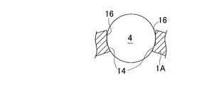
同玉軸受用保持器のボール案内面とボールとが接触した状態を示す断面図である。
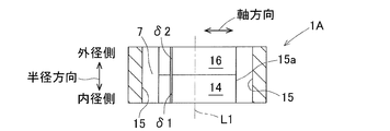
図8のX-X線断面図である。
同玉軸受用保持器を組み立てる前の環状体の断面図である。
この発明の第3実施形態に係る玉軸受用保持器の要部の斜視図である。
同玉軸受用保持器の要部を図11Aとは異なる方向から見た斜視図である。
同玉軸受用保持器の平面図である。
図12のXIII-XIII線断面図である。
この発明の第4実施形態に係る玉軸受用保持器の要部を拡大した図である。
同玉軸受用保持器のボール案内面とボールとが接触した状態を示す断面図である。
この発明の第5実施形態に係る玉軸受用保持器の要部の斜視図である。
この発明の第6実施形態に係る玉軸受用保持器の要部の斜視図である。
同玉軸受用保持器の要部を外径側から見た平面図である。
図18のXIX-XIX線断面図である。
同玉軸受用保持器のボール案内面とボールとが接触した状態を示す断面図である。
この発明の第7実施形態に係る玉軸受用保持器の要部の斜視図である。
同玉軸受用保持器の要部を図20Aとは異なる方向から見た斜視図である。
同玉軸受用保持器の平面図である。
図21のXXII-XXII線断面図である。
この発明の第8実施形態に係る玉軸受用保持器の要部の斜視図である。
従来の玉軸受用保持器のポケットを示す斜視図である。
従来の玉軸受のベルト荷重付加時の状態を説明する図である。
同玉軸受用保持器が一方向に偏り回転する状態を説明する図である。
グリース巻き込み時の状態を説明する図である。
この発明の第1実施形態を図1ないし図6と共に説明する。この実施形態に係る玉軸受用保持器は、例えば、モータの回転軸を回転自在に支持する深溝玉軸受の保持器に適用される。
[玉軸受について]
図1は、第1実施形態に係る玉軸受用保持器1を用いた玉軸受の断面図である。この玉軸受は、内輪2と、外輪3と、内外輪2,3間に介在する複数のボール4と、これらボール4を保持する保持器1と、内外輪2,3の軸方向両端に設けられたシール部材5,5とを有する。シール部材5,5により軸受空間が密閉されており、軸受空間には、グリースが封入されている。この保持器1はボール案内で外径拘束形である。この実施形態の場合のボール案内は、保持器1が内外輪2,3に接触しないように、ボール4を介して回転側輪となる内輪2に支持される形式である。ボール4は、例えば、鋼球やセラミックス等からなる。
図1は、第1実施形態に係る玉軸受用保持器1を用いた玉軸受の断面図である。この玉軸受は、内輪2と、外輪3と、内外輪2,3間に介在する複数のボール4と、これらボール4を保持する保持器1と、内外輪2,3の軸方向両端に設けられたシール部材5,5とを有する。シール部材5,5により軸受空間が密閉されており、軸受空間には、グリースが封入されている。この保持器1はボール案内で外径拘束形である。この実施形態の場合のボール案内は、保持器1が内外輪2,3に接触しないように、ボール4を介して回転側輪となる内輪2に支持される形式である。ボール4は、例えば、鋼球やセラミックス等からなる。
[保持器全体の概略構成]
保持器1は、軸受中心軸L回りの円環部6と、この円環部6の円周方向の複数箇所に設けられたポケット7とを有する。各ポケット7は円環部6を半径方向に貫通して設けられている。このポケット7内にボール4が保持されている。保持器1は、例えば、樹脂製であり、射出成型にて製作される。樹脂材料として、例えば、ポリアミド(PA)、ポリフェニレンサルファイド(PPS)、ポリエーテルエーテルケトン(PEEK)等の熱可塑性樹脂が用いられる。この保持器1に適用される樹脂には、強度を高めるために、例えば、ガラス繊維、カーボン繊維、アラミド繊維等の繊維が混合されている。なお、保持器1は、例えば、鉄板をプレス加工した波形保持器としても良い。
保持器1は、軸受中心軸L回りの円環部6と、この円環部6の円周方向の複数箇所に設けられたポケット7とを有する。各ポケット7は円環部6を半径方向に貫通して設けられている。このポケット7内にボール4が保持されている。保持器1は、例えば、樹脂製であり、射出成型にて製作される。樹脂材料として、例えば、ポリアミド(PA)、ポリフェニレンサルファイド(PPS)、ポリエーテルエーテルケトン(PEEK)等の熱可塑性樹脂が用いられる。この保持器1に適用される樹脂には、強度を高めるために、例えば、ガラス繊維、カーボン繊維、アラミド繊維等の繊維が混合されている。なお、保持器1は、例えば、鉄板をプレス加工した波形保持器としても良い。
[保持器1の連結構造について]
図2Aは、この保持器1の要部の斜視図であり、図2Bは図2Aの要部を拡大した図である。この保持器1は、各ポケット7を形成する球殻状板部8と、隣り合うポケット間の部分となる連結部9とが円周方向に交互に並ぶいわゆる波形保持器である。図3に示すように、この保持器1の円環部6は、円環部6の軸方向に互いに対向する二つの環状体10,10を有し、これら環状体10,10を軸方向に対向して組み合わせて複数のポケット7が形成される。この実施形態の二つの環状体10,10は互いに同一形状とし、表裏反対向きに組み合わせている。
図2Aは、この保持器1の要部の斜視図であり、図2Bは図2Aの要部を拡大した図である。この保持器1は、各ポケット7を形成する球殻状板部8と、隣り合うポケット間の部分となる連結部9とが円周方向に交互に並ぶいわゆる波形保持器である。図3に示すように、この保持器1の円環部6は、円環部6の軸方向に互いに対向する二つの環状体10,10を有し、これら環状体10,10を軸方向に対向して組み合わせて複数のポケット7が形成される。この実施形態の二つの環状体10,10は互いに同一形状とし、表裏反対向きに組み合わせている。
図4Aはこの保持器1の一部を外径側から見た平面図、図4Bは図4Aの一部を拡大した図である。各環状体10は、それぞれ半球状のポケット7を成す球殻状板部半体8aと、隣り合う半球状ポケット間の部分となる連結部半体9aとを有する。互いに対向する二つの球殻状板部半体8a,8aを組み合わせて球殻状板部8が形成される。また互いに対向する二つの連結部半体9a,9aを組み合わせて連結部9が形成される。連結部9は、二つの連結部半体9a,9aを組み合わせたときに面接触する合わせ面11を有する。この合わせ面11は軸方向に垂直な平面である。
連結部半体9aには、両側面に貫通する係合孔12が形成されている。一方の連結部半体9aには、他方の連結部半体9aに形成された係合孔12に挿入され係合される係合爪13が形成されている。係合孔12に係合段部12aが設けられる。係合爪13の先端部には、係合孔12の係合段部12aに係合する鉤部13aが形成されている。二つの環状体10,10を軸方向に互いに対向させ、一方の連結部半体9aの各係合爪13を、対応する他方の連結部半体9aの各係合孔12に挿入する。さらに各係合爪13の鉤部13aを、各係合孔12の係合段部12aに係合することで、二つの環状体10,10が互いに結合された波形保持器となる。
各球殻状板部半体8aには、軸方向に突出する突出壁部8aaが設けられる。詳細には、二つの環状体10,10が互いに結合された状態で、一方の球殻状板部半体8aにおける円周方向の一端に、他方の球殻状板部半体側に向かって軸方向に突出する突出壁部8aaが設けられている。他方の球殻状板部半体8aにおける円周方向の他端には、一方の球殻状板部半体側に向かって軸方向に突出する突出壁部8aaが設けられている。
また、二つの環状体10,10が互いに結合された状態で、他方の球殻状板部半体8aにおける円周方向の一端に、一方の球殻状板部半体8aの突出壁部8aaが嵌り込む嵌合凹部8abが設けられている。同様に、一方の球殻状板部半体8aにおける円周方向の他端に、他方の球殻状板部半体8aの突出壁部8aaが嵌り込む嵌合凹部8abが設けられている。突出壁部8aaの先端面と、この先端面に対向する嵌合凹部8abの底面との間には、微小な隙間が形成される。これら突出壁部8aaの先端面および嵌合凹部8abの底面は、ポケット7の軸方向中央から軸方向にずれた位置に形成されている。
[保持器1のポケット7について]
図5Aは図4BのV-V線断面図で、図5Bは保持器1のボール案内面とボールとが接触した状態を示す断面図である。図6Aは図4BのVI-VI線断面図であり、図6Bは保持器組立前の各環状体10の断面図である。図2B、図5A、5Bおよび図6A,6Bに示すように、各ポケット7の内面のうち円周方向に互いに対向する両側の円周方向対向部分に、半径方向の外径側部分に位置するボール案内面14,14が設けられている。このボール案内面14は、先端に向かうに従ってポケット中心軸L1に近づくように傾斜する断面形状(テーパ形状)に形成され、且つ、平面状に形成されている。このボール案内面14により、保持器1がボール案内で外径拘束形に構成されている。
図5Aは図4BのV-V線断面図で、図5Bは保持器1のボール案内面とボールとが接触した状態を示す断面図である。図6Aは図4BのVI-VI線断面図であり、図6Bは保持器組立前の各環状体10の断面図である。図2B、図5A、5Bおよび図6A,6Bに示すように、各ポケット7の内面のうち円周方向に互いに対向する両側の円周方向対向部分に、半径方向の外径側部分に位置するボール案内面14,14が設けられている。このボール案内面14は、先端に向かうに従ってポケット中心軸L1に近づくように傾斜する断面形状(テーパ形状)に形成され、且つ、平面状に形成されている。このボール案内面14により、保持器1がボール案内で外径拘束形に構成されている。
また、ポケット7内における軸受軸方向に互いに対向する両側に、軸方向案内面15,15が形成されている。軸方向案内面15は、ポケット中心軸L1に垂直な断面が円弧状となる円弧面で構成されている。ここで、「円弧面」は、円筒面および球面のいずれであっても良い。
上述の「平面状」とは、平面だけでなく、ボール案内面14がボール4と接触したとき(図5B)に点接触となるような、ポケット側に僅かに突出する曲面形状も含む。また、球殻状板部8は、二つの球殻状板部半体8a,8aを組み立てた状態で、対応する突出壁部8aaと嵌合凹部8abの底部との間には、溝状の隙間δが形成されている。隙間δのうち、ボール案内面14における溝状の隙間δ1は、ポケット7の軸方向中央部から軸方向にずれた位置に形成されている。この隙間δ1は軸受軸方向に垂直な方向に延び、後述する対向平面16における溝状の隙間δ2に連通する。
各ポケット7の両側の円周方向対向部分における、ボール案内面14以外の部分は、ポケット中心軸L1および軸受軸方向を含む平面に平行な平面形状である。これら互いに平面形状となる部分が、前記対向平面16を構成する。両側の円周方向対向部分において、ボール案内面14の基端が対向平面16に繋がる。対向平面16は、隣り合う軸方向案内面15における円弧の両側縁部15aよりもポケット拡径方向に凹入した位置に形成される。ボール案内面14の先端に、隣り合う軸方向案内面15における円弧の両側縁部15aが繋がっている。
溝状の隙間δのうち、対向平面16における、半径方向の外径側部分から中央付近に渡る隙間δ2もポケット7の軸方向中央から軸方向にずれた位置に形成されている。この隙間δ2は軸受軸方向に垂直な方向に延びる。この隙間δ2の軸方向位置は、ボール案内面14における隙間δ1と同一の軸方向位置で繋がっている。溝状の隙間δのうち、対向平面16における、半径方向の内径側部分の隙間δ3は、ポケット7のほぼ軸方向中央位置に形成されている。この半径方向の内径側部分の隙間δ3と、半径方向の中央付近の隙間δ2とは、軸受軸方向に延びる隙間δ4を介して連通する。
[試験条件、試験結果]
以上説明した保持器を備えた玉軸受を試験機に組込み、保持器に異音が発生するか否かの試験を行った。試験条件は以下の通りである。
<試験条件>
試験機:サーボモータ
ベルト荷重:3400N
回転速度:1000min-1→7000min-1→3000min-1→7000min-1
但し、1000min-1から7000min-1に、または3000min-1から7000min-1に回転速度を上げるとき1000min-1毎にステップアップし、7000min-1から3000min-1に回転速度を下げるとき1000min-1毎にステップダウンする。
判定方法:聴覚判定
以上説明した保持器を備えた玉軸受を試験機に組込み、保持器に異音が発生するか否かの試験を行った。試験条件は以下の通りである。
<試験条件>
試験機:サーボモータ
ベルト荷重:3400N
回転速度:1000min-1→7000min-1→3000min-1→7000min-1
但し、1000min-1から7000min-1に、または3000min-1から7000min-1に回転速度を上げるとき1000min-1毎にステップアップし、7000min-1から3000min-1に回転速度を下げるとき1000min-1毎にステップダウンする。
判定方法:聴覚判定

<試験結果>
同表1において、「○」は、聴覚判定により保持器に異音が発生していないことを表し、「×」は、聴覚判定により保持器に異音が発生したことを表す。試験結果によると、本実施形態の保持器は、各回転速度において異音が発生しなかった。
同表1において、「○」は、聴覚判定により保持器に異音が発生していないことを表し、「×」は、聴覚判定により保持器に異音が発生したことを表す。試験結果によると、本実施形態の保持器は、各回転速度において異音が発生しなかった。
[作用効果]
以上説明した保持器1によると、ポケット7の内面の円周方向対向部分における半径方向の外径側部分にボール案内面14が設けられ、このボール案内面14が、傾斜する断面形状で、且つ、平面状の形成されている。そのため、軸受運転時、ボール案内面14とボール4との接触は点接触となる。これにより、線接触の場合と比べて、ボール4に付着したグリースを保持器1のポケット内に巻き込み難くなる。したがって、引き摺り抵抗の低減を図ることができる。
以上説明した保持器1によると、ポケット7の内面の円周方向対向部分における半径方向の外径側部分にボール案内面14が設けられ、このボール案内面14が、傾斜する断面形状で、且つ、平面状の形成されている。そのため、軸受運転時、ボール案内面14とボール4との接触は点接触となる。これにより、線接触の場合と比べて、ボール4に付着したグリースを保持器1のポケット内に巻き込み難くなる。したがって、引き摺り抵抗の低減を図ることができる。
換言すれば、グリースがボール4に付着したままポケット内に一旦侵入しても、グリースは、ポケット7内に滞留することなく、ボール案内面14とボール4の接触点以外の略全周にわたる環状隙間から、ボール4に付着した状態のままポケット外に円滑に排出される。したがって、引き摺り抵抗の低減を図ることができる。これにより、瞬間的にボール公転速度が変化すること、および、ボール4から保持器1に加わる径方向内外の力のバランスが崩れることが防止され、その結果、保持器1が振れ廻ることを抑制できる。したがって、保持器1の振動を抑えて異音の低減を図ることができる。
また、ポケット7の両側の軸方向案内面15を、ポケット中心軸L1に垂直な断面が円弧状となる円弧面としている。そのため、保持器1を、例えば、高速回転域で使用して保持器1が弾性変形したときに、ポケット7の両側の軸方向案内面15とボール4との接触面圧が大きく変動することを防止できる。その結果、玉軸受の異常発熱や保持器1の摩耗を防止することができる。また、ポケット7の軸方向案内面15にグリースが滞留することが防止され、引き摺り抵抗の低減をさらに図ることができる。なお、この実施形態の高速回転域は5000min-1以上であるが、この回転速度に限定されない。
円環部6は、軸方向に互いに対向する二つの環状体10,10を軸方向に対向して組み合わせて構成され、複数のポケット7が形成されている。このため、内外輪2,3の軌道面間に複数のボール4を挿入した後、二つの環状体10,10を軸方向の両側から組み合わせて、保持器1を容易に組み立てることができる。
この保持器1を樹脂製として二つの環状体10,10を同一形状としているので、一種類の成形用金型で二つの環状体10,10を成形できる。このため、金型費用を抑えて保持器1のコスト低減を図れると共に、組み合わせる二つの環状体10,10を分別する必要がなく環状体10の管理も容易である。この保持器1を用いたモータ用の玉軸受の場合、モータの高速回転化をより図ることができる。つまり、モータを高速回転させても玉軸受からの異音を低減できる。
[他の実施形態について]
以下の説明においては、各実施形態で先行する実施形態で説明している事項に対応している部分には同一の参照符号を付し、重複する説明を省略する。構成の一部のみを説明している場合、構成の他の部分は、特に記載のない限り先行して説明している実施形態と同様とする。同一の構成から同一の作用効果を奏する。各実施形態で具体的に説明している部分の組合せばかりではなく、特に組合せに支障が生じなければ、実施形態同士を部分的に組合せることも可能である。
以下の説明においては、各実施形態で先行する実施形態で説明している事項に対応している部分には同一の参照符号を付し、重複する説明を省略する。構成の一部のみを説明している場合、構成の他の部分は、特に記載のない限り先行して説明している実施形態と同様とする。同一の構成から同一の作用効果を奏する。各実施形態で具体的に説明している部分の組合せばかりではなく、特に組合せに支障が生じなければ、実施形態同士を部分的に組合せることも可能である。
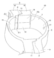
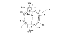
図7は、第2実施形態に係る玉軸受用保持器1Aの要部の斜視図であり、図8は、この玉軸受用保持器1Aの要部を外径側から見た平面図である。図9Aは、図8のIX-IX線断面図で、図9Bはボール案内面とボールとが接触した状態を示す断面図である。図10Aは、図8のX-X線断面図であり、図10Bは保持器組立前の各環状体10の断面図である。図7~図10に示すように、この保持器1Aはボール案内で内径拘束形である。この保持器1Aは、ポケット7の内面の円周方向対向部分に半径方向の内径側部分に、ボール案内面14が設けられ、このボール案内面14が、傾斜する断面形状で、且つ、平面状に形成されている。
溝状の隙間δのうち、ボール案内面14における、突出壁部8aaと嵌合凹部8abとの間の隙間δ1は、ポケット7の軸方向中央から軸方向にずれた位置に形成されている。この隙間δ1は、軸受軸方向に垂直な方向に延び、対向平面16の隙間δ2に連通する。対向平面16における、半径方向の内外に渡る隙間δ2も、ポケット7の軸方向中央から軸方向にずれた位置に形成されている。
この保持器1Aによると、ポケット7の内面の円周方向対向部分に半径方向の内径側部分にボール案内面14が設けられ、このボール案内面14が、傾斜する断面形状で、且つ、平面状に形成されている。そのため、軸受運転時、ボール案内面14とボール4との接触は点接触となる(図9B)。これにより、線接触の場合と比べて、ボール4に付着したグリースを保持器1Aのポケット7内に巻き込み難くなる。その他、第1実施形態と同様の作用効果を奏する。
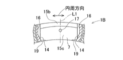
図11A,11Bは、第3実施形態に係る玉軸受用保持器1Bの要部の斜視図である。図11A,11Bは、それぞれ玉軸受用保持器1Bを異なる方向から見た斜視図である。図12は同玉軸受用保持器1Bの平面図で、図13は図12のXIII-XIII線断面図である。
図11~図13に示すように、この保持器1Bは、各ポケット7の両側の軸方向案内面15,15に、凸部17がそれぞれ設けられている。軸方向案内面15における半径方向の外径側部分15bは円錐面に形成されている。つまり、軸方向案内面15における半径方向の外径側部分15bには、先端に向かうに従ってポケット中心軸に近づくように傾斜する断面形状に形成した軸方向のボール案内面が設けられている。軸方向案内面15における外径側部分15b以外は、ポケット中心軸L1に垂直な断面が円弧状となる円弧面15cで構成されている。各円弧面15cに、凸部17が設けられている。
凸部17は、両側の軸方向案内面15における、ボールがポケット内で自転する軸心L2付近に設けられ、ポケット側に半球状に突出するボス部のように形成されている。凸部17の直径および突出量は、例えば、試験、シミュレーション等の結果によりボール直径の数%に定められる。ただし、この実施形態の値に限定されるものではない。凸部17は、軸受運転時の遠心力で円環部6が変形してポケット7の形状が変形したときに円環部6とボール4との接触範囲が増大するのを抑制する。この実施形態では、各軸方向案内面15に凸部17を一つずつ設けているが、凸部17を複数設けても良い。
図11A,図11B、図12に示すように、この保持器1Bには、グリースが保持器1Bの軸受軸方向の側面を伝わって直接内外輪軌道面に入ることを防止するフランジ18が設けられている。この実施形態では、連結部9における軸受軸方向を向く側面、および球殻状板部8における軸受軸方向を向く側面のうち、半径方向の外径側部分に軸受軸方向に突出するフランジ18が設けられている。このフランジ18は軸受軸方向の両側にそれぞれ設けられている。
連結部9における、両側フランジ18,18を含む保持器1Bの幅寸法と、球殻状板部8における、両側フランジ18,18を含む保持器1Bの幅寸法とは同一である。連結部9における軸方向一方のフランジ18と、球殻状板部8における軸方向一方のフランジ18とは、軸方向先端位置が同一となるように形成されている。軸方向他方のフランジ18についても同様である。
球殻状板部8には、グリースがポケット7内に浸入することを抑制する内側フランジ19が設けられている。具体的には、球殻状板部8におけるポケット7の内面のうち、円周方向に互いに対向する両側の半径方向内径側縁部に、ポケット内側に突出する内側フランジ19が設けられている。この内側フランジ19は平面視円弧状(図12)に形成されている。なお、両側の軸方向案内面15に内側フランジ19がほとんど設けられていないのは、つぎの理由による。仮に、グリースが遠心力によりポケット7の軸方向案内面15から浸入しても、この軸方向案内面15に凸部17があるので、グリースはポケット内に滞留することなく、軸方向案内面15とボールの点接触以外の隙間からポケット外に円滑に排出される。その他の構成は、図7~図10の第2実施形態の保持器と同様である。
この保持器1Bによると、軸受運転時に遠心力で円環部6が変形してポケット7の形状が変形したときに、軸方向案内面15の凸部17にボールを接触させる。特に、この実施形態では、軸方向案内面15における半径方向の外径側部分15bに、円錐面状のボール案内面が設けられている。そのため、凸部17がない場合、ポケット7の形状が弾性変形したときに、円錐面状のボール案内面にボールが過度に線接触することが考えられる。
しかしながら、前述のように軸方向案内面15に凸部17が設けられているので、円錐面状のボール案内面にボールが線接触することなく、軸方向案内面15の凸部17にボールを点接触させることができる。したがって、軸方向案内面15に対するボールの接触面圧を抑えて玉軸受が異常発熱すること、および保持器1Bが摩耗することを確実に防止できる。また、軸方向案内面15の凸部17と球形のボールとの接触は点接触となることにより、線接触の場合と比べて、ボールに付着したグリースを保持器1Bのポケット内に巻き込み難くなる。したがって引き摺り抵抗の低減を図ることができる。さらに、両側の軸方向案内面15,15における、ボールが自転する軸心L2付近に凸部17が設けられているので、ボールを安定して自転および公転させることができる。これにより、保持器1Bの振れ廻りをより確実に抑えることができる。
連結部における側面に、軸受軸方向に突出するフランジ18が設けられているので、グリースが保持器1Bの軸受軸方向の側面を伝わって直接内外輪軌道面に入ることを防止できる。特に、フランジ18が半径方向の外径側部分に付設されているので、軸受運転時の遠心力により保持器側面のグリースが半径方向の内径側から外径側に移動することをより確実に抑制し、グリースが外輪軌道面に過剰に浸入することを防止できる。したがって、過剰なグリースがボールに付着してポケット内に浸入することを未然に防止することができる。これにより、グリースを保持器1Bのポケット内に巻き込み難くなる。その結果、引き摺り抵抗の低減を図ることができる。
また、軸受運転時グリースが遠心力によりポケット内に浸入しようとするが、内側フランジ19が設けられているので、グリースがポケット内に過度に浸入することを抑制できる。これにより、グリースをポケット内にさらに巻き込み難くなる。したがって、引き摺り抵抗の低減を確実に図ることができる。
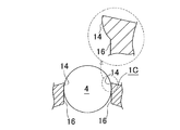
図14は、第4実施形態に係る玉軸受用保持器1Cの要部の斜視図で、図15は、ボール案内面とボールとが接触した状態を示す断面図である。第4実施形態では、ボール案内面14が、軸受中心軸Lに垂直な断面がポケット中心軸L1側に円弧状に突出する断面形状で、且つ、軸受軸方向に沿って延びる部分円柱面状の形状(いわゆる蒲鉾形状)に形成されている。このボール案内面14により、この保持器1はボール案内で外径拘束形に構成される。その他の構成は第1実施形態と同じである。
第4実施形態の保持器1Cによると、ボール案内面14が、軸受中心軸Lに垂直な断面がポケット中心軸L1側に円弧状に突出する断面形状であるので、軸受運転時、ボール案内面14と球形のボール4との接触は点接触となる。これにより、線接触の場合と比べて、ボール4に付着したグリースを保持器1のポケット内に巻き込み難くなる。したがって引き摺り抵抗の低減を図ることができる。
また、ボール案内面14が、軸受中心軸Lに垂直な断面がポケット中心軸L1側に円弧状に突出する断面形状で、且つ、軸受軸方向に沿って延びる部分円柱面状の形状であるから、保持器1を金型で成形した場合に成形品である環状体10を軸方向に円滑に抜き易くすることができる。さらに、遠心力や熱の影響によりポケット7の形状が変形した場合でも、軸受軸方向に沿って延びる部分円柱面状のボール案内面14と、球形のボール4との接触を確実に点接触とすることで、ボール4に付着した潤滑剤をポケット7内に巻き込み難くすることができる。したがって、引き摺り抵抗の低減をより確実に図れる。
図16は、第5実施形態に係る玉軸受用保持器1Aaの要部の斜視図である。この保持器1Aaは、図7の第2実施形態の保持器1Aに対して、ポケット7の内面の円周方向対向部分に位置するボール案内面14が、軸受軸方向中央のみで円弧状に突出する形状となっている。その他の構成は図7の第2実施形態の保持器1Aと同様である。第5実施形態の保持器1Aaも、第2実施形態の保持器1Aと同様の効果を奏する。
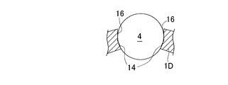
図17は、第6実施形態に係る玉軸受用保持器1Dの要部の斜視図であり、図18はこの玉軸受用保持器1Dの要部を外径側から見た平面図である。図19Aは図18のXIX-XIX線断面図である。図17~図19A,19Bに示すように、第6実施形態の保持器1Dはボール案内で内径拘束形である。保持器1Dにおける各ポケット7の両側の軸方向案内面15,15に、凸部17が設けられている。また、ポケット7の内面の円周方向対向部分に、半径方向の内径側部分に位置するボール案内面14が設けられている。ボール案内面14は、軸受中心軸L(図1)に垂直な断面がポケット中心軸L1側に円弧状に突出する断面形状で、且つ、軸受軸方向に沿って延びる部分円柱面状の形状としている。
第6実施形態の保持器1Dによると、ポケット7の内面の円周方向対向部分に半径方向の内径側部分に位置するボール案内面14が設けられ、このボール案内面14が、軸受中心軸Lに垂直な断面がポケット中心軸L1側に円弧状に突出する断面形状で、且つ、軸受軸方向に沿って延びる部分円柱面状の形状である。そのため、軸受運転時、ボール案内面14と球形のボール4との接触は点接触となる(図19B)。これにより、線接触の場合と比べて、ボール4に付着したグリースを保持器1Dのポケット7内に巻き込み難くなる。その他、前述の実施形態と同様の作用効果を奏する。
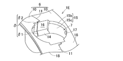
図20A,20Bは、第7実施形態に係る玉軸受用保持器1Eの要部の斜視図である。図20A,20Bは、それぞれ玉軸受用保持器1Eを異なる方向から見た斜視図である。図21は同玉軸受用保持器1Eの平面図であり、図22は図21のXXII-XXII線断面図である。図20A,20B~図22に示すように、第7実施形態の保持器1Eでは、各ポケット7の両側の軸方向案内面15,15に、凸部17が設けられている。
軸方向案内面15における半径方向の外径側部分15bは円錐面に形成されている。つまり、軸方向案内面15における半径方向の外径側部分15bは、軸方向のボール案内面を構成しており、このボール案内面は、先端に向かうに従ってポケット中心軸に近づくように傾斜する断面形状に形成されている。軸方向案内面15における外径側部分15b以外の面は、ポケット中心軸L1に垂直な断面が円弧状となる円弧面15cで形成されている。各円弧面15cに、凸部17が設けられている。
図20A,20Bおよび図21に示すように、第7実施形態の保持器1Eには、グリースが保持器1Eの軸受軸方向の側面を伝わって直接内外輪軌道面に入ることを防止するフランジ18が設けられている。この実施形態では、連結部9における軸受軸方向を向く側面、および球殻状板部8における軸受軸方向を向く側面のうち、半径方向の外径側部分に軸受軸方向に突出するフランジ18が設けられている。このフランジ18は軸受軸方向の両側にそれぞれ設けられている。
このようなフランジ18を設けることで、グリースが保持器1Eの軸受軸方向の側面を伝わって直接内外輪軌道面に入ることを防止できる。特に、フランジ18を半径方向の外径側部分に付設したので、軸受運転時の遠心力により保持器側面のグリースが半径方向の内径側から外径側に移動することをより確実に抑制し、グリースが外輪軌道面に過剰に侵入することを防止できる。したがって、過剰なグリースがボールに付着してポケット内に浸入することを未然に防止することができる。これにより、グリースを保持器1Eのポケット内に巻き込み難くなる。その結果、引き摺り抵抗の低減を図ることができる。その他、前述の実施形態と同様の作用効果を奏する。
図23は、第8実施形態に係る玉軸受用保持器1Daの要部の斜視図である。第8実施形態の保持器1Daは、図17の第6実施形態の保持器1Dに対して、ポケット7の内面の円周方向対向部分に位置するボール案内面14が、軸受軸方向中央のみで円弧状に突出する形状となっている。その他の構成は、図17の第6実施形態の保持器1Dと同様である。
第8実施形態の保持器1Daによると、ボール案内面14を、軸受中心軸L(図19A)に垂直な断面がポケット中心軸側に円弧状に突出する断面形状としたので、軸受運転時、ボール案内面14と球形のボール4(図1)との接触は点接触となる。これにより、線接触の場合と比べて、ボール4(図1)に付着したグリースを保持器1Daのポケット内に巻き込み難くなる。したがって引き摺り抵抗の低減を図ることができる。
各実施形態において、以下の変形例を適用可能である。
保持器は樹脂製のみに限定されず金属製であっても良い。例えば黄銅を機械加工して形成しても良い。この場合、保持器は二つの環状体からなる合わせ保持器でなくても良い。
フランジを設ける箇所は半径方向の外径側部分に限定されるものではない。例えば、連結部等における側面のうち、半径方向の内径側部分または半径方向の中央付近部分に軸受軸方向に突出するフランジを設けても良い。
保持器は樹脂製のみに限定されず金属製であっても良い。例えば黄銅を機械加工して形成しても良い。この場合、保持器は二つの環状体からなる合わせ保持器でなくても良い。
フランジを設ける箇所は半径方向の外径側部分に限定されるものではない。例えば、連結部等における側面のうち、半径方向の内径側部分または半径方向の中央付近部分に軸受軸方向に突出するフランジを設けても良い。
潤滑剤としてグリースに代えて潤滑油を適用しても良い。この場合、例えばVG32以上の粘度の潤滑油が考えられる。各保持器を用いる玉軸受として、アンギュラ玉軸受を適用しても良い。上記各実施形態の玉軸受は両側シールタイプとしているが、片側のみにシールを設けても良いし、両シールのないいわゆるオープンタイプとしても良い。これら玉軸受をモータ以外の用途に適用することも可能である。この場合にも玉軸受からの異音を低減できる。
以上説明した各実施形態は、以下の態様を含む。
[態様1]
態様1に係る玉軸受用保持器は、軸受中心軸回りの円環部の円周方向の複数箇所に、この円環部を半径方向に貫通して設けられたポケット内にボールを保持するボール案内の玉軸受用保持器であって、
前記ポケットの内面のうち前記円周方向に互いに対向する両側の円周方向対向部分に、前記半径方向の外径側部分または前記半径方向の内径側部分のいずれか一方に位置して、前記ボール案内とするボール案内面が設けられ、
このボール案内面が、先端に向かうに従ってポケット中心軸に近づくように傾斜する断面形状に形成され、且つ、平面状とされ、
前記ポケットの軸受軸方向に互いに対向する両側の軸方向案内面が、前記ポケット中心軸に垂直な断面が円弧状となる円弧面とされている。
態様1に係る玉軸受用保持器は、軸受中心軸回りの円環部の円周方向の複数箇所に、この円環部を半径方向に貫通して設けられたポケット内にボールを保持するボール案内の玉軸受用保持器であって、
前記ポケットの内面のうち前記円周方向に互いに対向する両側の円周方向対向部分に、前記半径方向の外径側部分または前記半径方向の内径側部分のいずれか一方に位置して、前記ボール案内とするボール案内面が設けられ、
このボール案内面が、先端に向かうに従ってポケット中心軸に近づくように傾斜する断面形状に形成され、且つ、平面状とされ、
前記ポケットの軸受軸方向に互いに対向する両側の軸方向案内面が、前記ポケット中心軸に垂直な断面が円弧状となる円弧面とされている。
[態様2]
態様2に係る玉軸受用保持器は、態様1に記載の玉軸受用保持器において、前記円環部は、この円環部の軸方向に互いに対向する二つの環状体を有し、これら環状体を前記軸方向に対向して組み合わせて複数の前記ポケットが形成されている。
態様2に係る玉軸受用保持器は、態様1に記載の玉軸受用保持器において、前記円環部は、この円環部の軸方向に互いに対向する二つの環状体を有し、これら環状体を前記軸方向に対向して組み合わせて複数の前記ポケットが形成されている。
[態様3]
態様3に係るモータ用の玉軸受は、態様1または態様2に記載の玉軸受用保持器を用いている。
態様3に係るモータ用の玉軸受は、態様1または態様2に記載の玉軸受用保持器を用いている。
[態様4]
態様4に係る玉軸受用保持器は、軸受中心軸回りの円環部の円周方向の複数箇所に、この円環部を半径方向に貫通して設けられたポケット内にボールを保持するボール案内の玉軸受用保持器であって、
前記ポケットの内面のうち前記円周方向に互いに対向する両側の円周方向対向部分に、前記半径方向の外径側部分または前記半径方向の内径側部分のいずれか一方に位置して、前記ボール案内とするボール案内面が設けられ、
このボール案内面が、前記軸受中心軸に垂直な断面がポケット中心軸側に円弧状に突出する断面形状とされている。
態様4に係る玉軸受用保持器は、軸受中心軸回りの円環部の円周方向の複数箇所に、この円環部を半径方向に貫通して設けられたポケット内にボールを保持するボール案内の玉軸受用保持器であって、
前記ポケットの内面のうち前記円周方向に互いに対向する両側の円周方向対向部分に、前記半径方向の外径側部分または前記半径方向の内径側部分のいずれか一方に位置して、前記ボール案内とするボール案内面が設けられ、
このボール案内面が、前記軸受中心軸に垂直な断面がポケット中心軸側に円弧状に突出する断面形状とされている。
[態様5]
態様5に係る玉軸受用保持器は、態様4に記載の玉軸受用保持器において、前記ボール案内面が、前記軸受中心軸に垂直な断面がポケット中心軸側に円弧状に突出する断面形状で、且つ、軸受軸方向に沿って延びる部分円柱面状の形状とされている。
態様5に係る玉軸受用保持器は、態様4に記載の玉軸受用保持器において、前記ボール案内面が、前記軸受中心軸に垂直な断面がポケット中心軸側に円弧状に突出する断面形状で、且つ、軸受軸方向に沿って延びる部分円柱面状の形状とされている。
[態様6]
態様6に係る玉軸受用保持器は、態様4または態様5に記載の玉軸受用保持器において、前記各ポケットを形成する球殻状板部と、隣り合うポケット間の部分となる連結部とが円周方向に交互に並ぶ波形保持器であり、
少なくとも前記連結部における軸受軸方向を向く側面に、前記軸受軸方向に突出するフランジが設けられている。
態様6に係る玉軸受用保持器は、態様4または態様5に記載の玉軸受用保持器において、前記各ポケットを形成する球殻状板部と、隣り合うポケット間の部分となる連結部とが円周方向に交互に並ぶ波形保持器であり、
少なくとも前記連結部における軸受軸方向を向く側面に、前記軸受軸方向に突出するフランジが設けられている。
[態様7]
態様7に係るモータ用の玉軸受は、態様4から態様6のいずれか1態様に記載の玉軸受用保持器を用いている。
態様7に係るモータ用の玉軸受は、態様4から態様6のいずれか1態様に記載の玉軸受用保持器を用いている。
[態様8]
態様8に係る玉軸受用保持器は、軸受中心軸回りの円環部の円周方向の複数箇所に、この円環部を半径方向に貫通して設けられたポケット内にボールを保持するボール案内の玉軸受用保持器であって、
前記ポケットの軸受軸方向に互いに対向する両側の軸方向案内面に、遠心力で前記円環部が変形して前記ポケットの形状が変形したときに、前記ボールと当接して前記円環部と前記ボールとの接触範囲の増大を抑制する凸部が設けられている。
態様8に係る玉軸受用保持器は、軸受中心軸回りの円環部の円周方向の複数箇所に、この円環部を半径方向に貫通して設けられたポケット内にボールを保持するボール案内の玉軸受用保持器であって、
前記ポケットの軸受軸方向に互いに対向する両側の軸方向案内面に、遠心力で前記円環部が変形して前記ポケットの形状が変形したときに、前記ボールと当接して前記円環部と前記ボールとの接触範囲の増大を抑制する凸部が設けられている。
[態様9]
態様9に係る玉軸受用保持器は、態様8に記載の玉軸受用保持器において、前記各ポケットを形成する球殻状板部と、隣合うポケット間の部分となる連結部とが円周方向に交互に並ぶ波形保持器であり、
少なくとも前記連結部における軸受軸方向を向く側面に、前記軸受軸方向に突出するフランジが設けられている。
態様9に係る玉軸受用保持器は、態様8に記載の玉軸受用保持器において、前記各ポケットを形成する球殻状板部と、隣合うポケット間の部分となる連結部とが円周方向に交互に並ぶ波形保持器であり、
少なくとも前記連結部における軸受軸方向を向く側面に、前記軸受軸方向に突出するフランジが設けられている。
[態様10]
態様10に係る玉軸受用保持器は、態様8または態様9に記載の玉軸受用保持器において、前記円環部は、この円環部の軸方向に互いに対向する二つの環状体を有し、これら環状体を前記軸方向に対向して組み合わせて複数の前記ポケットが形成されている。
態様10に係る玉軸受用保持器は、態様8または態様9に記載の玉軸受用保持器において、前記円環部は、この円環部の軸方向に互いに対向する二つの環状体を有し、これら環状体を前記軸方向に対向して組み合わせて複数の前記ポケットが形成されている。
[態様11]
態様11に係る玉軸受用保持器は、態様8から態様10のいずれか1態様に記載の玉軸受用保持器において、前記ポケットの内面のうち前記円周方向に互いに対向する両側の円周方向対向部分に、前記半径方向の外径側部分または前記半径方向の内径側部分のいずれか一方に位置して、前記ボール案内とするボール案内面が設けられ、
このボール案内面が、先端に向かうに従ってポケット中心軸に近づくように傾斜する断面形状に形成され、且つ、平面状とされ、
前記両側の軸方向案内面は、前記ポケット中心軸に垂直な断面が円弧状となる円弧面とされている。
態様11に係る玉軸受用保持器は、態様8から態様10のいずれか1態様に記載の玉軸受用保持器において、前記ポケットの内面のうち前記円周方向に互いに対向する両側の円周方向対向部分に、前記半径方向の外径側部分または前記半径方向の内径側部分のいずれか一方に位置して、前記ボール案内とするボール案内面が設けられ、
このボール案内面が、先端に向かうに従ってポケット中心軸に近づくように傾斜する断面形状に形成され、且つ、平面状とされ、
前記両側の軸方向案内面は、前記ポケット中心軸に垂直な断面が円弧状となる円弧面とされている。
[態様12]
態様12に係る玉軸受用保持器は、態様8から態様10のいずれか1態様に記載の玉軸受用保持器において、前記ポケットの内面のうち前記円周方向に互いに対向する両側の円周方向対向部分に、前記半径方向の外径側部分または前記半径方向の内径側部分のいずれか一方に位置して、前記ボール案内とするボール案内面が設けられ、
このボール案内面は、前記軸受中心軸に垂直な断面がポケット中心軸側に円弧状に突出する断面形状とされている。
態様12に係る玉軸受用保持器は、態様8から態様10のいずれか1態様に記載の玉軸受用保持器において、前記ポケットの内面のうち前記円周方向に互いに対向する両側の円周方向対向部分に、前記半径方向の外径側部分または前記半径方向の内径側部分のいずれか一方に位置して、前記ボール案内とするボール案内面が設けられ、
このボール案内面は、前記軸受中心軸に垂直な断面がポケット中心軸側に円弧状に突出する断面形状とされている。
[態様13]
態様13に係る玉軸受用保持器は、態様12に記載の玉軸受用保持器において、前記ボール案内面は、前記軸受中心軸に垂直な断面がポケット中心軸側に円弧状に突出する断面形状で、且つ、軸受軸方向に沿って延びる部分円柱面状の形状とされている。
態様13に係る玉軸受用保持器は、態様12に記載の玉軸受用保持器において、前記ボール案内面は、前記軸受中心軸に垂直な断面がポケット中心軸側に円弧状に突出する断面形状で、且つ、軸受軸方向に沿って延びる部分円柱面状の形状とされている。
[態様14]
態様14に係るモータ用の玉軸受は、態様8ないし請求項13のいずれか1態様に記載の玉軸受用保持器を用いている。
態様14に係るモータ用の玉軸受は、態様8ないし請求項13のいずれか1態様に記載の玉軸受用保持器を用いている。
[態様15]
態様15に係る玉軸受用保持器は、軸受中心軸回りの円環部の円周方向の複数箇所に、この円環部を半径方向に貫通して設けられたポケット内にボールを保持するボール案内の玉軸受用保持器であり、前記各ポケットを形成する球殻状板部と、隣り合うポケット間の部分となる連結部とが円周方向に交互に並ぶ玉軸受用波形保持器であって、
少なくとも前記連結部における軸受軸方向を向く側面に、前記軸受軸方向に突出するフランジが設けられている。
態様15に係る玉軸受用保持器は、軸受中心軸回りの円環部の円周方向の複数箇所に、この円環部を半径方向に貫通して設けられたポケット内にボールを保持するボール案内の玉軸受用保持器であり、前記各ポケットを形成する球殻状板部と、隣り合うポケット間の部分となる連結部とが円周方向に交互に並ぶ玉軸受用波形保持器であって、
少なくとも前記連結部における軸受軸方向を向く側面に、前記軸受軸方向に突出するフランジが設けられている。
[態様16]
態様16に係る玉軸受用波形保持器は、態様15に記載の玉軸受用波形保持器において、前記円環部は、この円環部の軸方向に互いに対向する二つの環状体を有し、これら環状体を前記軸方向に対向して組み合わせて複数の前記ポケットが形成されている。
態様16に係る玉軸受用波形保持器は、態様15に記載の玉軸受用波形保持器において、前記円環部は、この円環部の軸方向に互いに対向する二つの環状体を有し、これら環状体を前記軸方向に対向して組み合わせて複数の前記ポケットが形成されている。
[態様17]
態様17に係るモータ用の玉軸受は、態様15または態様16に記載の玉軸受用波形保持器を用いている。
態様17に係るモータ用の玉軸受は、態様15または態様16に記載の玉軸受用波形保持器を用いている。
以上のとおり、図面を参照しながら好適な実施形態を説明したが、当業者であれば、本件明細書を見て、自明な範囲内で種々の変更および修正を容易に想定するであろう。したがって、そのような変更および修正は、添付の特許請求の範囲から定まるこの発明の範囲内またはこれと均等の範囲内のものと解釈される。
1,1A,1Aa,1B,1C,1D,1Da,1E…保持器
4…ボール
6…円環部
7…ポケット
8…球殻状板部
9…連結部
10…環状体
14…ボール案内面
15…軸方向案内面
17…凸部
18…フランジ
4…ボール
6…円環部
7…ポケット
8…球殻状板部
9…連結部
10…環状体
14…ボール案内面
15…軸方向案内面
17…凸部
18…フランジ
Claims (8)
- 軸受中心軸回りの円環部の円周方向の複数箇所に、この円環部を半径方向に貫通して設けられたポケット内にボールを保持するボール案内の玉軸受用保持器であって、
前記ポケットの内面のうち前記円周方向に互いに対向する両側の円周方向対向部分に、前記半径方向の外径側部分または前記半径方向の内径側部分のいずれか一方に位置して、前記ボールを案内するボール案内面が設けられ、
このボール案内面は、先端に向かうに従ってポケット中心軸に近づくように傾斜する断面形状で、且つ、平面状に形成されている玉軸受用保持器。 - 請求項1に記載の玉軸受用保持器において、前記円環部は、この円環部の軸方向に互いに対向する二つの環状体を有し、これら環状体を前記軸方向に対向して組み合わせて複数の前記ポケットが形成されている玉軸受用保持器。
- 請求項1または2に記載の玉軸受用保持器において、前記ボール案内面は、前記軸受中心軸に垂直な断面がポケット中心軸側に円弧状に突出する断面形状である玉軸受用保持器。
- 請求項1から3のいずれか一項に記載の玉軸受用保持器において、前記ボール案内面は、前記軸受中心軸に垂直な断面がポケット中心軸側に円弧状に突出する断面形状で、且つ、軸受軸方向に沿って延びる部分円柱面状の形状である玉軸受用保持器。
- 請求項1から4のいずれか一項に記載の玉軸受用保持器において、前記各ポケットを形成する球殻状板部と、隣り合うポケット間の部分となる連結部とが円周方向に交互に並ぶ波形保持器であり、
少なくとも前記連結部における軸受軸方向を向く側面に、前記軸受軸方向に突出するフランジが設けられている玉軸受用保持器。 - 請求項1から5のいずれか一項に記載の玉軸受用保持器において、前記ポケットの軸受軸方向に互いに対向する両側の軸方向案内面に、遠心力で前記円環部が変形して前記ポケットの形状が変形したときに、前記ボールと当接して前記円環部と前記ボールとの接触範囲の増大を抑制する凸部が設けられている玉軸受用保持器。
- 請求項6に記載の玉軸受用保持器において、前記両側の軸方向案内面は、前記ポケット中心軸に垂直な断面が円弧状となる円弧面で形成されている玉軸受用保持器。
- 請求項1から7のいずれか一項に記載の玉軸受用保持器を用いたモータ用の玉軸受。
Applications Claiming Priority (14)
| Application Number | Priority Date | Filing Date | Title |
|---|---|---|---|
| JP2015-015425 | 2015-01-29 | ||
| JP2015-015199 | 2015-01-29 | ||
| JP2015015199 | 2015-01-29 | ||
| JP2015015425A JP6505446B2 (ja) | 2015-01-29 | 2015-01-29 | 玉軸受用波形保持器およびその玉軸受用波形保持器を用いた玉軸受 |
| JP2015-019837 | 2015-02-04 | ||
| JP2015019837 | 2015-02-04 | ||
| JP2015027165 | 2015-02-16 | ||
| JP2015-027165 | 2015-02-16 | ||
| JP2016-003302 | 2016-01-12 | ||
| JP2016003301A JP2016145640A (ja) | 2015-02-04 | 2016-01-12 | 玉軸受用保持器およびその玉軸受用保持器を用いた玉軸受 |
| JP2016-003300 | 2016-01-12 | ||
| JP2016003302A JP2016153690A (ja) | 2015-01-29 | 2016-01-12 | 玉軸受用保持器およびその玉軸受用保持器を用いた玉軸受 |
| JP2016003300A JP2016145639A (ja) | 2015-01-29 | 2016-01-12 | 玉軸受用保持器およびその玉軸受用保持器を用いた玉軸受 |
| JP2016-003301 | 2016-01-12 |
Publications (1)
| Publication Number | Publication Date |
|---|---|
| WO2016121562A1 true WO2016121562A1 (ja) | 2016-08-04 |
Family
ID=56543180
Family Applications (1)
| Application Number | Title | Priority Date | Filing Date |
|---|---|---|---|
| PCT/JP2016/051347 Ceased WO2016121562A1 (ja) | 2015-01-29 | 2016-01-19 | 玉軸受用保持器およびその玉軸受用保持器を用いた玉軸受 |
Country Status (1)
| Country | Link |
|---|---|
| WO (1) | WO2016121562A1 (ja) |
Cited By (1)
| Publication number | Priority date | Publication date | Assignee | Title |
|---|---|---|---|---|
| DE102016221801A1 (de) * | 2016-11-08 | 2017-12-21 | Schaeffler Technologies AG & Co. KG | Wälzlagerkäfig und Kugellager mit einem solchen Wälzlagerkäfig |
Citations (5)
| Publication number | Priority date | Publication date | Assignee | Title |
|---|---|---|---|---|
| JP2004084782A (ja) * | 2002-08-27 | 2004-03-18 | Nsk Ltd | ラジアル玉軸受 |
| JP2008202755A (ja) * | 2007-02-22 | 2008-09-04 | Nsk Ltd | 転がり軸受 |
| JP2008286387A (ja) * | 2007-04-18 | 2008-11-27 | Ntn Corp | 自動車補機用軸受 |
| JP2010091091A (ja) * | 2008-10-10 | 2010-04-22 | Ntn Corp | 転がり軸受用保持器およびctスキャナ用転がり軸受 |
| JP2012255479A (ja) * | 2011-06-08 | 2012-12-27 | Ntn Corp | 玉軸受用保持器および玉軸受 |
-
2016
- 2016-01-19 WO PCT/JP2016/051347 patent/WO2016121562A1/ja not_active Ceased
Patent Citations (5)
| Publication number | Priority date | Publication date | Assignee | Title |
|---|---|---|---|---|
| JP2004084782A (ja) * | 2002-08-27 | 2004-03-18 | Nsk Ltd | ラジアル玉軸受 |
| JP2008202755A (ja) * | 2007-02-22 | 2008-09-04 | Nsk Ltd | 転がり軸受 |
| JP2008286387A (ja) * | 2007-04-18 | 2008-11-27 | Ntn Corp | 自動車補機用軸受 |
| JP2010091091A (ja) * | 2008-10-10 | 2010-04-22 | Ntn Corp | 転がり軸受用保持器およびctスキャナ用転がり軸受 |
| JP2012255479A (ja) * | 2011-06-08 | 2012-12-27 | Ntn Corp | 玉軸受用保持器および玉軸受 |
Cited By (1)
| Publication number | Priority date | Publication date | Assignee | Title |
|---|---|---|---|---|
| DE102016221801A1 (de) * | 2016-11-08 | 2017-12-21 | Schaeffler Technologies AG & Co. KG | Wälzlagerkäfig und Kugellager mit einem solchen Wälzlagerkäfig |
Similar Documents
| Publication | Publication Date | Title |
|---|---|---|
| JP5876237B2 (ja) | 玉軸受用の合成樹脂製保持器および玉軸受 | |
| JP6841067B2 (ja) | 玉軸受 | |
| JP6922928B2 (ja) | 転がり軸受用保持器、及び転がり軸受 | |
| JP7535372B2 (ja) | 玉軸受用保持器および転がり軸受 | |
| JP6935856B2 (ja) | アンギュラ玉軸受 | |
| TWI620880B (zh) | 斜角滾珠軸承 | |
| JP2009156422A (ja) | 深溝玉軸受 | |
| CN203202013U (zh) | 角接触球轴承 | |
| JP5228654B2 (ja) | 円すいころ軸受用保持器及び円すいころ軸受 | |
| WO2016121562A1 (ja) | 玉軸受用保持器およびその玉軸受用保持器を用いた玉軸受 | |
| JP2016153685A (ja) | 転がり軸受 | |
| JP2018105504A (ja) | アンギュラ玉軸受 | |
| JP2025032024A (ja) | 転がり軸受および転がり軸受用保持器 | |
| JP6505446B2 (ja) | 玉軸受用波形保持器およびその玉軸受用波形保持器を用いた玉軸受 | |
| JP2016145639A (ja) | 玉軸受用保持器およびその玉軸受用保持器を用いた玉軸受 | |
| JP5715001B2 (ja) | ラジアル玉軸受 | |
| JP6892787B2 (ja) | 冠型保持器及びそれを備えた転がり軸受 | |
| WO2016088521A1 (ja) | 合成樹脂製保持器および玉軸受 | |
| JP2008175239A (ja) | 玉軸受用冠型保持器及び玉軸受 | |
| JP2016153690A (ja) | 玉軸受用保持器およびその玉軸受用保持器を用いた玉軸受 | |
| WO2020059829A1 (ja) | 玉軸受用保持器および転がり軸受 | |
| JP2016145640A (ja) | 玉軸受用保持器およびその玉軸受用保持器を用いた玉軸受 | |
| JP2014005913A (ja) | 転がり軸受 | |
| JP4424092B2 (ja) | 合成樹脂製の冠形保持器 | |
| JP7526585B2 (ja) | 転がり軸受の保持器および転がり軸受 |
Legal Events
| Date | Code | Title | Description |
|---|---|---|---|
| 121 | Ep: the epo has been informed by wipo that ep was designated in this application |
Ref document number: 16743166 Country of ref document: EP Kind code of ref document: A1 |
|
| NENP | Non-entry into the national phase |
Ref country code: DE |
|
| 122 | Ep: pct application non-entry in european phase |
Ref document number: 16743166 Country of ref document: EP Kind code of ref document: A1 |