WO2016121334A1 - 燃料ポンプ - Google Patents
燃料ポンプ Download PDFInfo
- Publication number
- WO2016121334A1 WO2016121334A1 PCT/JP2016/000248 JP2016000248W WO2016121334A1 WO 2016121334 A1 WO2016121334 A1 WO 2016121334A1 JP 2016000248 W JP2016000248 W JP 2016000248W WO 2016121334 A1 WO2016121334 A1 WO 2016121334A1
- Authority
- WO
- WIPO (PCT)
- Prior art keywords
- inner gear
- foot
- gear
- insertion hole
- pump
- Prior art date
- Legal status (The legal status is an assumption and is not a legal conclusion. Google has not performed a legal analysis and makes no representation as to the accuracy of the status listed.)
- Ceased
Links
Images






Classifications
-
- F—MECHANICAL ENGINEERING; LIGHTING; HEATING; WEAPONS; BLASTING
- F04—POSITIVE - DISPLACEMENT MACHINES FOR LIQUIDS; PUMPS FOR LIQUIDS OR ELASTIC FLUIDS
- F04C—ROTARY-PISTON, OR OSCILLATING-PISTON, POSITIVE-DISPLACEMENT MACHINES FOR LIQUIDS; ROTARY-PISTON, OR OSCILLATING-PISTON, POSITIVE-DISPLACEMENT PUMPS
- F04C2/00—Rotary-piston machines or pumps
- F04C2/08—Rotary-piston machines or pumps of intermeshing-engagement type, i.e. with engagement of co-operating members similar to that of toothed gearing
- F04C2/10—Rotary-piston machines or pumps of intermeshing-engagement type, i.e. with engagement of co-operating members similar to that of toothed gearing of internal-axis type with the outer member having more teeth or tooth-equivalents, e.g. rollers, than the inner member
-
- F—MECHANICAL ENGINEERING; LIGHTING; HEATING; WEAPONS; BLASTING
- F04—POSITIVE - DISPLACEMENT MACHINES FOR LIQUIDS; PUMPS FOR LIQUIDS OR ELASTIC FLUIDS
- F04C—ROTARY-PISTON, OR OSCILLATING-PISTON, POSITIVE-DISPLACEMENT MACHINES FOR LIQUIDS; ROTARY-PISTON, OR OSCILLATING-PISTON, POSITIVE-DISPLACEMENT PUMPS
- F04C2/00—Rotary-piston machines or pumps
- F04C2/08—Rotary-piston machines or pumps of intermeshing-engagement type, i.e. with engagement of co-operating members similar to that of toothed gearing
- F04C2/082—Details specially related to intermeshing engagement type machines or pumps
- F04C2/084—Toothed wheels
-
- F—MECHANICAL ENGINEERING; LIGHTING; HEATING; WEAPONS; BLASTING
- F04—POSITIVE - DISPLACEMENT MACHINES FOR LIQUIDS; PUMPS FOR LIQUIDS OR ELASTIC FLUIDS
- F04C—ROTARY-PISTON, OR OSCILLATING-PISTON, POSITIVE-DISPLACEMENT MACHINES FOR LIQUIDS; ROTARY-PISTON, OR OSCILLATING-PISTON, POSITIVE-DISPLACEMENT PUMPS
- F04C15/00—Component parts, details or accessories of machines, pumps or pumping installations, not provided for in groups F04C2/00 - F04C14/00
- F04C15/0057—Driving elements, brakes, couplings, transmission specially adapted for machines or pumps
- F04C15/0061—Means for transmitting movement from the prime mover to driven parts of the pump, e.g. clutches, couplings, transmissions
-
- F—MECHANICAL ENGINEERING; LIGHTING; HEATING; WEAPONS; BLASTING
- F02—COMBUSTION ENGINES; HOT-GAS OR COMBUSTION-PRODUCT ENGINE PLANTS
- F02M—SUPPLYING COMBUSTION ENGINES IN GENERAL WITH COMBUSTIBLE MIXTURES OR CONSTITUENTS THEREOF
- F02M37/00—Apparatus or systems for feeding liquid fuel from storage containers to carburettors or fuel-injection apparatus; Arrangements for purifying liquid fuel specially adapted for, or arranged on, internal-combustion engines
- F02M37/04—Feeding by means of driven pumps
- F02M37/08—Feeding by means of driven pumps electrically driven
-
- F—MECHANICAL ENGINEERING; LIGHTING; HEATING; WEAPONS; BLASTING
- F04—POSITIVE - DISPLACEMENT MACHINES FOR LIQUIDS; PUMPS FOR LIQUIDS OR ELASTIC FLUIDS
- F04C—ROTARY-PISTON, OR OSCILLATING-PISTON, POSITIVE-DISPLACEMENT MACHINES FOR LIQUIDS; ROTARY-PISTON, OR OSCILLATING-PISTON, POSITIVE-DISPLACEMENT PUMPS
- F04C15/00—Component parts, details or accessories of machines, pumps or pumping installations, not provided for in groups F04C2/00 - F04C14/00
-
- F—MECHANICAL ENGINEERING; LIGHTING; HEATING; WEAPONS; BLASTING
- F04—POSITIVE - DISPLACEMENT MACHINES FOR LIQUIDS; PUMPS FOR LIQUIDS OR ELASTIC FLUIDS
- F04C—ROTARY-PISTON, OR OSCILLATING-PISTON, POSITIVE-DISPLACEMENT MACHINES FOR LIQUIDS; ROTARY-PISTON, OR OSCILLATING-PISTON, POSITIVE-DISPLACEMENT PUMPS
- F04C15/00—Component parts, details or accessories of machines, pumps or pumping installations, not provided for in groups F04C2/00 - F04C14/00
- F04C15/0057—Driving elements, brakes, couplings, transmission specially adapted for machines or pumps
- F04C15/0061—Means for transmitting movement from the prime mover to driven parts of the pump, e.g. clutches, couplings, transmissions
- F04C15/0073—Couplings between rotors and input or output shafts acting by interengaging or mating parts, i.e. positive coupling of rotor and shaft
-
- F—MECHANICAL ENGINEERING; LIGHTING; HEATING; WEAPONS; BLASTING
- F04—POSITIVE - DISPLACEMENT MACHINES FOR LIQUIDS; PUMPS FOR LIQUIDS OR ELASTIC FLUIDS
- F04C—ROTARY-PISTON, OR OSCILLATING-PISTON, POSITIVE-DISPLACEMENT MACHINES FOR LIQUIDS; ROTARY-PISTON, OR OSCILLATING-PISTON, POSITIVE-DISPLACEMENT PUMPS
- F04C15/00—Component parts, details or accessories of machines, pumps or pumping installations, not provided for in groups F04C2/00 - F04C14/00
- F04C15/0057—Driving elements, brakes, couplings, transmission specially adapted for machines or pumps
- F04C15/008—Prime movers
-
- F—MECHANICAL ENGINEERING; LIGHTING; HEATING; WEAPONS; BLASTING
- F04—POSITIVE - DISPLACEMENT MACHINES FOR LIQUIDS; PUMPS FOR LIQUIDS OR ELASTIC FLUIDS
- F04C—ROTARY-PISTON, OR OSCILLATING-PISTON, POSITIVE-DISPLACEMENT MACHINES FOR LIQUIDS; ROTARY-PISTON, OR OSCILLATING-PISTON, POSITIVE-DISPLACEMENT PUMPS
- F04C2/00—Rotary-piston machines or pumps
- F04C2/08—Rotary-piston machines or pumps of intermeshing-engagement type, i.e. with engagement of co-operating members similar to that of toothed gearing
- F04C2/10—Rotary-piston machines or pumps of intermeshing-engagement type, i.e. with engagement of co-operating members similar to that of toothed gearing of internal-axis type with the outer member having more teeth or tooth-equivalents, e.g. rollers, than the inner member
- F04C2/102—Rotary-piston machines or pumps of intermeshing-engagement type, i.e. with engagement of co-operating members similar to that of toothed gearing of internal-axis type with the outer member having more teeth or tooth-equivalents, e.g. rollers, than the inner member the two members rotating simultaneously around their respective axes
-
- F—MECHANICAL ENGINEERING; LIGHTING; HEATING; WEAPONS; BLASTING
- F04—POSITIVE - DISPLACEMENT MACHINES FOR LIQUIDS; PUMPS FOR LIQUIDS OR ELASTIC FLUIDS
- F04C—ROTARY-PISTON, OR OSCILLATING-PISTON, POSITIVE-DISPLACEMENT MACHINES FOR LIQUIDS; ROTARY-PISTON, OR OSCILLATING-PISTON, POSITIVE-DISPLACEMENT PUMPS
- F04C13/00—Adaptations of machines or pumps for special use, e.g. for extremely high pressures
- F04C13/001—Pumps for particular liquids
-
- F—MECHANICAL ENGINEERING; LIGHTING; HEATING; WEAPONS; BLASTING
- F04—POSITIVE - DISPLACEMENT MACHINES FOR LIQUIDS; PUMPS FOR LIQUIDS OR ELASTIC FLUIDS
- F04C—ROTARY-PISTON, OR OSCILLATING-PISTON, POSITIVE-DISPLACEMENT MACHINES FOR LIQUIDS; ROTARY-PISTON, OR OSCILLATING-PISTON, POSITIVE-DISPLACEMENT PUMPS
- F04C2210/00—Fluid
- F04C2210/10—Fluid working
- F04C2210/1044—Fuel
-
- F—MECHANICAL ENGINEERING; LIGHTING; HEATING; WEAPONS; BLASTING
- F04—POSITIVE - DISPLACEMENT MACHINES FOR LIQUIDS; PUMPS FOR LIQUIDS OR ELASTIC FLUIDS
- F04C—ROTARY-PISTON, OR OSCILLATING-PISTON, POSITIVE-DISPLACEMENT MACHINES FOR LIQUIDS; ROTARY-PISTON, OR OSCILLATING-PISTON, POSITIVE-DISPLACEMENT PUMPS
- F04C2230/00—Manufacture
- F04C2230/60—Assembly methods
- F04C2230/603—Centering; Aligning
-
- F—MECHANICAL ENGINEERING; LIGHTING; HEATING; WEAPONS; BLASTING
- F04—POSITIVE - DISPLACEMENT MACHINES FOR LIQUIDS; PUMPS FOR LIQUIDS OR ELASTIC FLUIDS
- F04C—ROTARY-PISTON, OR OSCILLATING-PISTON, POSITIVE-DISPLACEMENT MACHINES FOR LIQUIDS; ROTARY-PISTON, OR OSCILLATING-PISTON, POSITIVE-DISPLACEMENT PUMPS
- F04C2240/00—Components
- F04C2240/30—Casings or housings
-
- F—MECHANICAL ENGINEERING; LIGHTING; HEATING; WEAPONS; BLASTING
- F04—POSITIVE - DISPLACEMENT MACHINES FOR LIQUIDS; PUMPS FOR LIQUIDS OR ELASTIC FLUIDS
- F04C—ROTARY-PISTON, OR OSCILLATING-PISTON, POSITIVE-DISPLACEMENT MACHINES FOR LIQUIDS; ROTARY-PISTON, OR OSCILLATING-PISTON, POSITIVE-DISPLACEMENT PUMPS
- F04C2240/00—Components
- F04C2240/40—Electric motor
-
- F—MECHANICAL ENGINEERING; LIGHTING; HEATING; WEAPONS; BLASTING
- F04—POSITIVE - DISPLACEMENT MACHINES FOR LIQUIDS; PUMPS FOR LIQUIDS OR ELASTIC FLUIDS
- F04C—ROTARY-PISTON, OR OSCILLATING-PISTON, POSITIVE-DISPLACEMENT MACHINES FOR LIQUIDS; ROTARY-PISTON, OR OSCILLATING-PISTON, POSITIVE-DISPLACEMENT PUMPS
- F04C2240/00—Components
- F04C2240/60—Shafts
Definitions
- the present disclosure relates to a fuel pump that sequentially sucks fuel into each pump chamber and then discharges the fuel.
- the fuel pump disclosed in Patent Document 1 includes an outer gear having a plurality of inner teeth, an outer gear having a plurality of outer teeth, and an outer gear that is eccentrically engaged with (fitted to) the outer gear, and rotatably accommodates both gears.
- a pump housing and an electric motor having a rotary shaft that is driven to rotate are provided.
- the outer gear and the inner gear rotate while expanding or reducing the volume of the pump chamber formed between the two gears (toward the rotation progress side), so that the fuel is sequentially sucked into each pump chamber and then discharged.
- the coupling connects the rotating shaft and the inner gear.
- the protruding portion that protrudes in the radial direction is engaged with the inner wall groove of the inner gear.
- the present disclosure has been made in view of the problems described above, and an object thereof is to provide a fuel pump with high pump efficiency.
- an outer gear having a plurality of inner teeth, an inner gear having a plurality of outer teeth and eccentrically engaging with the outer gear in an eccentric direction, and the outer gear and the inner gear are rotatable.
- a joint member that relays the rotation shaft to the inner gear, and the outer gear and the inner gear each have a volume of a pump chamber formed between the two gears.
- a leg that extends along the axial direction from the main body, and is inserted with a gap in the insertion hole, and protrudes from the foot toward the rotation progression side of the inner gear, at the apex And having a protrusion width is reduced in the Cow Hodojiku direction.
- the joint member having the main body portion fitted to the rotating shaft rotates together with the rotating shaft.
- the inner gear becomes rotatable.
- the protruding portion protrudes from the foot portion toward the rotation progression side of the inner gear, the inner gear rotates while the protruding portion contacts the inner peripheral wall of the inner gear. According to this, even when the rotation axis is displaced and the joint member is inclined, it is possible to avoid the foot from contacting the edge portion of the insertion hole. Therefore, the inner gear can be prevented from being pushed by receiving a force in the axial direction and can rotate smoothly, so that a fuel pump with high pump efficiency can be provided.
- the second aspect of the present disclosure includes an outer gear having a plurality of inner teeth, an inner gear having a plurality of outer teeth, the outer gear being eccentrically fitted in an eccentric direction, and rotating the outer gear and the inner gear.
- a pump housing that can be accommodated, an electric motor having a rotating shaft that is driven to rotate, and a joint member that rotates the inner shaft in the circumferential direction by relaying the rotating shaft to the inner gear.
- the outer gear and the inner gear are both gears.
- the fuel is sequentially sucked into each pump chamber and then discharged, and the inner gear has an insertion hole recessed along the axial direction, and a joint member Has a main body portion that fits into the rotation shaft, and a foot portion that extends along the axial direction from the main body portion and is inserted with a gap in the insertion hole.
- the inner wall on the drive rotation side with respect to the portion has a flat portion along the radial direction, and the foot portion has a top portion facing the flat portion in the circumferential direction and curved in a convex shape in plan view.
- the joint member having the main body portion fitted to the rotating shaft rotates together with the rotating shaft.
- leg part extended along an axial direction from a main-body part is inserted in the insertion hole of the inner gear with the clearance gap, the inner gear rotates to the circumferential direction by relay of a joint member.
- the inner wall on the drive rotation side with respect to the foot portion has a flat portion along the radial direction.
- the top part which curves convexly in planar view has opposed the flat part in the circumferential direction.
- the driving force transmitted from the joint member to the inner gear has a radial component force. Since generation
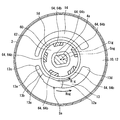
- FIG. 2 is a sectional view taken along line II-II in FIG.
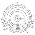
- FIG. 3 is a sectional view taken along line III-III in FIG. 1.
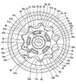
- FIG. 4 is a sectional view taken along line IV-IV in FIG. 1. It is the figure which looked at the inner gear in 1st Embodiment from the arrangement
- FIG. 9 is a diagram corresponding to FIG. 8 in Modification 1.
- FIG. 9 is a diagram corresponding to FIG. 8 in Modification 3.
- FIG. 10 is a diagram corresponding to FIG. 8 in Modification 6. It is a fragmentary sectional front view which shows the fuel pump in 2nd Embodiment.
- FIG. 14 is a cross-sectional plan view of a cross section taken along line XIV-XIV in FIG. 13.
- FIG. 14 is a cross-sectional plan view of a cross section taken along line XV-XV in FIG. 13.
- FIG. 14 is a cross-sectional plan view of a cross section taken along line XVI-XVI in FIG. 13.
- It is a top view of the inner gear in 2nd Embodiment. It is the elements on larger scale which show the relationship between the insertion hole and foot part of 2nd Embodiment. It is a top view of the joint member in a 2nd embodiment.
- FIG. 20 is a sectional view taken along line XX-XX in FIG. 19.
- FIG. 19 is a diagram corresponding to FIG. 18 in an example of modification 10;
- FIG. 19 is a diagram corresponding to FIG. 18 in another example of Modification Example 10.
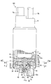
- the fuel pump 100 is a positive displacement trochoid pump mounted on a vehicle.
- the fuel pump 100 includes a side cover 5 projecting outward from an end opposite to the pump body 3 with the pump body 3 and the electric motor 4 housed in the cylindrical pump body 2 in the axial direction.
- the side cover 5 includes an electrical connector 5a for energizing the electric motor 4 and a discharge port 5b for discharging fuel.
- the rotating shaft 4a of the electric motor 4 is rotationally driven by energization from an external circuit via the electrical connector 5a.
- the fuel sucked and pressurized by the pump body 3 using the driving force of the rotating shaft 4a of the electric motor 4 is discharged from the discharge port 5b.
- the light oil whose viscosity is higher than gasoline is discharged as a fuel.
- an inner rotor type brushless motor in which magnets are arranged in four poles is employed as the electric motor 4.
- the rotation shaft 4a of the electric motor 4 is rotated in the reverse direction to the normal rotation direction (that is, rotated in the reverse direction with respect to the rotation direction Rig described later) at the time of startup.
- the rotation progress side refers to the side that is the positive direction of the rotation direction Rig.
- the rotation reverse side indicates a side that is the negative direction of the rotation direction Rig.
- the pump body 3 includes a pump housing 10, an inner gear 20, an outer gear 30, and a joint member 60.
- the pump housing 10 is formed by overlapping a pump cover 12 and a pump casing 16.
- the pump cover 12 is formed in a disk shape from metal.
- the pump cover 12 projects outward from an end of the pump body 2 opposite to the side cover 5 with the electric motor 4 sandwiched in the axial direction.
- the pump cover 12 shown in FIGS. 1 and 2 has a cylindrical hole-like suction port 12a and an arc-shaped groove-like suction passage 13 for sucking fuel from the outside.
- the suction port 12 a passes through a specific opening location Ss eccentric from the inner center line Cig of the inner gear 20 in the pump cover 12 along the axial direction of the cover 12.
- the suction passage 13 is open to the pump casing 16 side of the pump cover 12.
- the inner peripheral portion 13 a of the suction passage 13 extends along the rotational direction Rig (see also FIG. 4) of the inner gear 20 to a length of less than half a circumference.
- the outer peripheral part 13b of the suction passage 13 extends along the rotational direction Rog of the outer gear 30 to a length of less than a half circumference.
- the suction passage 13 is widened from the start end portion 13c toward the end portion 13d in the rotational directions Rig and Rog.
- the suction passage 13 communicates with the suction port 12a by opening the suction port 12a at the opening portion Ss of the groove bottom 13e.
- the width of the suction passage 13 is set to be smaller than the diameter of the suction port 12 a in the entire opening portion Ss where the suction port 12 a opens.
- the pump cover 12 forms a recessed hole-shaped arrangement space 58 in which the main body 62 of the joint member 60 is rotatably arranged at a position facing the inner gear 20 on the inner center line Cig.
- the pump casing 16 shown in FIGS. 1, 3 and 4 is formed of a metal into a bottomed cylindrical shape.
- the opening 16 a in the pump casing 16 is covered with the pump cover 12, so that the entire circumference is sealed.
- the inner peripheral portion 13 a of the pump casing 16 is formed in a cylindrical hole shape that is eccentric from the inner center line Cig of the inner gear 20 as shown in FIGS.
- the pump casing 16 has an arc-hole-like discharge passage 17 for discharging fuel from the discharge port 5 b through the fuel passage 6 between the pump body 2 and the electric motor 4.
- the discharge passage 17 penetrates the concave bottom portion 16c of the pump casing 16 along the axial direction.
- the inner peripheral portion 17 a of the discharge passage 17 extends along the rotational direction Rig of the inner gear 20 to a length of less than half a circumference.
- the outer peripheral part 17 b of the discharge passage 17 extends along the rotational direction Rog of the outer gear 30 to a length of less than a half circumference.
- the discharge passage 17 is reduced in width toward the end portion 17d in the rotational directions Rig and Rog from the start end portion 17c.
- the pump casing 16 has a reinforcing rib 16d in the discharge passage 17.
- the reinforcing rib 16 d is formed integrally with the pump casing 16, and is a rib that reinforces the pump casing 16 by straddling the discharge passage 17 in a direction crossing the rotational direction Rig of the inner gear 20.
- a radial bearing 50 is fitted and fixed on the inner center line Cig of the concave bottom portion 16 c of the pump casing 16 in order to radially support the rotating shaft 4 a of the electric motor 4.
- a thrust bearing 52 is fitted and fixed on the inner center line Cig of the pump cover 12 in order to support the rotary shaft 4a in the axial direction.
- the concave bottom portion 16c and the inner peripheral portion 16b of the pump casing 16 define a housing space 56 for housing the inner gear 20 and the outer gear 30 together with the pump cover 12.
- the inner gear 20 and the outer gear 30 are so-called trochoid gears in which the tooth profile curve of each tooth is a trochoid curve.
- the inner gear 20 shown in FIGS. 1, 4 and 5 is arranged eccentrically in the accommodation space 56 by sharing the inner center line Cig with the rotation shaft 4a.
- the inner peripheral portion 22 of the inner gear 20 is radially supported by a radial bearing 50, and the sliding surfaces 25 on both axial sides are supported by the concave bottom portion 16 c of the pump casing 16 and the pump cover 12.
- the inner gear 20 has an insertion hole 27 that is recessed along the axial direction at a location facing the arrangement space 58.
- a plurality of insertion holes 27 are provided in the circumferential direction along the rotation direction Rig, and each insertion hole 27 penetrates to the concave bottom portion 16c side.
- the inner gear 20 has a plurality of external teeth 24 a arranged at equal intervals in the rotation direction Rig on the outer peripheral portion 24.
- Each external tooth 24a can be opposed to each of the passages 13 and 17 and the grooves 14 and 18 in the axial direction according to the rotation of the inner gear 20, so that sticking to the concave bottom portion 16c and the pump cover 12 is suppressed. ing.
- each insertion hole 27 of the present embodiment has a planar planar portion along the radial direction of the inner gear 20 on the inner circumferential wall on the rotation progression side and the inner circumferential wall on the rotation opposite side of the inner circumferential wall 27a. 27b, 27c.
- the outer gear 30 shown in FIGS. 1 and 4 is arranged coaxially in the accommodation space 56 by being eccentric with respect to the inner center line Cig of the inner gear 20.
- the inner gear 20 is eccentric with respect to the outer gear 30 in the eccentric direction De as one radial direction.
- the outer peripheral portion 34 of the outer gear 30 is supported in the radial direction by the inner peripheral portion 16 b of the pump casing 16, and is supported in the axial direction by the concave bottom portion 16 c of the pump casing 16 and the pump cover 12. With these bearings, the outer gear 30 is rotatable in a certain rotational direction Rog around the outer center line Cog that is eccentric from the inner center line Cig.
- the outer gear 30 has a plurality of inner teeth 32a arranged at equal intervals in the rotation direction Rog in the inner peripheral portion 32.
- the number of the inner teeth 32a in the outer gear 30 is set to be one more than the number of the outer teeth 24a in the inner gear 20.
- Each internal tooth 32a can be opposed to each of the passages 13 and 17 and the grooves 14 and 18 in the axial direction according to the rotation of the outer gear 30, so that sticking to the concave bottom portion 16c and the pump cover 12 is suppressed. ing.
- the inner gear 20 meshes with the outer gear 30 by relative eccentricity in the eccentric direction De. Accordingly, a plurality of pump chambers 40 are formed between the gears 20 and 30 in the accommodating space 56. The volume of the pump chamber 40 expands and contracts as the outer gear 30 and the inner gear 20 rotate.
- the volume of the pump chamber 40 increases in the pump chamber 40 that communicates with the suction passage 13 and the suction groove 18.
- fuel is sucked into the pump chamber 40 through the suction passage 13 from the suction port 12a.
- the suction passage 13 is widened from the start end portion 13c toward the end portion 13d (see also FIG. 2), the amount of fuel sucked through the suction passage 13 is the volume expansion amount of the pump chamber 40.
- the volume of the pump chamber 40 is reduced in the pump chamber 40 that is in communication with the discharge passage 17 and the discharge groove 14.
- fuel is discharged from the pump chamber 40 to the fuel passage 6 through the discharge passage 17.
- the discharge passage 17 is reduced in width from the start end portion 13c toward the end portion 13d (see also FIG. 3)
- the amount of fuel discharged through the discharge passage 17 is reduced in volume of the pump chamber 40. It depends on the amount.
- the joint member 60 is formed of a synthetic resin such as polyphenylene sulfide resin and relays the rotating shaft 4a to the inner gear 20.
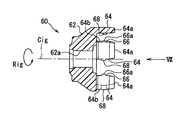
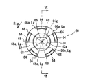
- the joint member 60 has a main body 62, a foot 64, a protrusion 66, and a reverse protrusion 68.
- the main body 62 is disposed in an arrangement space 58 formed in the pump cover 12, and is formed in an annular shape having a fitting hole 62a opened at the center, and the rotating shaft 4a is inserted into the fitting hole 62a. Thus, it is fitted and fixed to the rotating shaft 4a.
- a plurality of foot portions 64 are provided corresponding to the number of insertion holes 27 of the inner gear 20.
- the foot 64 is provided with a number that is a prime number and a number that avoids the number of poles of the magnet of the electric motor 4.
- Each such leg part 64 is provided along with the circumferential direction.
- Each foot 64 extends from the main body 62 along the axial direction, and is inserted into the corresponding insertion hole 27 with a gap.
- the distal end 64a of each foot 64 reaches the electric motor 4 side of the center of gravity of the inner gear 20 in the axial direction with respect to each insertion hole 27 penetrating the inner gear 20 in the axial direction. It extends so as not to reach.
- a plurality of protruding portions 66 are provided corresponding to the number of each insertion hole 27 and each foot portion 64. Each protruding portion 66 protrudes from the corresponding foot portion 64 toward the rotation direction of the inner gear 20. Each protrusion 66 of this embodiment protrudes from the main body 62 side of the tip 64a so as to avoid the tip 64a of each foot 64.
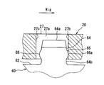
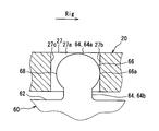
- Each protrusion 66 is formed such that the width in the axial direction becomes narrower toward the apex 66a. Specifically, the protruding portion 66 protrudes in a curved convex shape having a curvature in the axial direction. More specifically, as shown in FIG. 7, the protruding portion 66 protrudes in a partial cylindrical surface shape having a generatrix Lg along the radial direction. ing. Each vertex 66a is located in the insertion hole 27 together with the tip 64a of the corresponding foot 64 (see also FIG. 8).
- each reverse protrusion 68 protrudes from the corresponding foot 64 toward the rotation reverse side of the inner gear 20.
- Each reverse projecting portion 68 projects in the same shape as the projecting portion 66, and has a substantially line symmetrical shape with the projecting portion 66 across the bisector of the foot portion 64.
- each foot portion 64 is relative to the main body portion 62 and the corresponding protruding portion 66, and to the main body portion 62 and the corresponding reverse protruding portion 68. It has a constricted shape.
- the joint member 60 formed of a resin material there is a concern about the wear of the protrusion 66 due to contact.
- the curved convex surface portion deviated from the apex portion 66a according to the angle makes contact with the flat surface portion 27b, thereby avoiding that only a specific portion is significantly worn. is doing.
- thermal expansion, swelling due to fuel, or deformation of the foot due to the contact may occur.
- a portion of the curved convex surface portion of the protruding portion 66 contacts the flat portion 27b.
- the driving force of the rotating shaft 4a is transmitted to the inner gear 20 through the joint member 60, and the inner gear 20 is rotated in the rotational direction Rig. Then, the fuel is sequentially sucked into the pump chambers 40 by the fuel pump 100 and discharged from the pump chambers 40.
- the joint member 60 having the main body portion 62 fitted to the rotating shaft 4a rotates together with the rotating shaft 4a.
- leg part 64 extended along the axial direction from the main-body part 62 is inserted in the insertion hole 27 of the inner gear 20 with the clearance gap, the inner gear 20 becomes rotatable.
- the protruding portion 66 protrudes from the foot portion 64 toward the rotation progression side of the inner gear 20, the inner gear 20 rotates while the protruding portion 66 contacts the inner peripheral wall 27 a of the inner gear 20.
- the inner gear 20 can be prevented from being pushed by receiving a force in the axial direction and can be smoothly rotated, so that the fuel pump 100 with high pump efficiency can be provided.
- the protruding portion 66 protrudes in a curved convex shape having a curvature in the axial direction.
- the curved projecting portion 66 can contact the insertion hole 27 along the axial direction. For this reason, it is possible to more reliably avoid the inner gear 20 from being pushed by receiving a force in the axial direction and to rotate smoothly, so that the pump efficiency can be increased.
- the insertion hole 27 has the flat surface portion 27b along the radial direction on the inner peripheral wall 27a on the rotation advance side with respect to the protrusion 66, and the protrusion 66 is along the radial direction. It protrudes in the shape of a partial cylindrical surface having a generatrix Lg. Since the projecting portion 66 is in line contact with the flat portion 27b, the driving force of the rotating shaft 4a is efficiently transmitted in the rotational direction Rig, so that the inner gear 20 can be smoothly rotated and the pump efficiency can be increased.
- the protruding portion 66 protrudes from the main body 62 side than the tip 64 a of the foot portion 64. Therefore, when manufacturing the fuel pump 100, the tip 64a of the foot 64 can be easily inserted into the insertion hole 27, and the tip 64a of the foot 64 functions as a guide, so that the protrusion 66 is inserted into the insertion hole 27. It is also easy to insert. Therefore, the joint member 60 can be easily assembled to the inner gear 20.
- a plurality of insertion holes 27 are provided, and a plurality of feet 64 and protrusions 66 are provided corresponding to the insertion holes 27. According to this, when the rotation shaft 4a is displaced and the joint member 60 is inclined, the protrusion 66 can be brought into contact with the inner peripheral wall 27a of the insertion hole 27 corresponding to various inclinations. Efficiency can be increased.
- the joint member 60 has the reverse projecting portion 68 that projects in the same shape as the projecting portion 66 from the foot portion 64 toward the reverse side of the inner gear 20. According to this, even when the rotating shaft 4a rotates in the reverse direction when the electric motor 4 is started, for example, the foot 64 and the edge of the insertion hole 27 come into contact with each other and the inner gear 20 receives a force in the axial direction. Thus, the inner gear 20 can be smoothly rotated.
- the protruding portion 66 may protrude from the tip 64 a of the foot portion 64 toward the rotation progression side of the inner gear 20.
- the projecting portion 66 may project in a spherical shape, for example, as a curved convex surface having a curvature in the axial direction.
- the protrusion 66 whose width in the axial direction becomes narrower toward the vertex 66 a has an inclined surface 67 that is inclined with respect to the axial direction, and the vertex 66 a is pointed. Can be adopted.
- the protruding portion 66 may protrude from one or more of the plurality of foot portions 64, even if not from all the foot portions 64.
- the joint member 60 may not have the reverse protrusion 68.
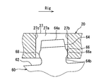
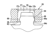
- the insertion hole 27 may have a tapered surface 28 at the edge portion as shown in FIG.
- the foot portion 64 when the rotation shaft 4 a is displaced and the joint member 60 is inclined, the foot portion 64 also has the tapered surface 28 of the insertion hole 27 against the insertion hole 27. It is possible to avoid contact with the included edge portion.
- the insertion hole 27 may not have the flat surface portion 27b along the radial direction on the inner peripheral wall 27a on the rotation advance side with respect to the protruding portion 66.
- the insertion hole 27 may have a cross-sectional shape such as a circular shape or an elliptical shape.
- the fuel pump 100 may suck and discharge gasoline other than light oil or liquid fuel based thereon as fuel.
- the fuel pump 101 is a positive displacement trochoid pump mounted on a vehicle.
- the fuel pump 101 includes a side cover 105 that projects outward from an end opposite to the pump body 103 with the pump body 103 and the electric motor 104 housed in the cylindrical pump body 102 in the axial direction.
- the side cover 105 includes an electrical connector 105a for energizing the electric motor 104 and a discharge port 105b for discharging fuel.
- the rotating shaft 104a of the electric motor 104 is rotationally driven by energization from an external circuit via the electrical connector 105a.
- the fuel sucked and pressurized by the rotation of the outer gear 130 and the inner gear 120 of the pump body 103 using the driving force of the rotating shaft 104a of the electric motor 104 is discharged from the discharge port 105b.
- the light oil whose viscosity is higher than gasoline is discharged as a fuel.
- an inner rotor type brushless motor in which the magnet 104b is formed in 4 poles and the coil 104c is formed in 6 slots is employed.
- the electric motor 104 performs positioning control to rotate the rotating shaft 104a to the drive rotation side or the drive rotation reverse side. Thereafter, the electric motor 104 performs drive control to rotate the rotary shaft 104a toward the drive rotation side from the position positioned by the positioning control.
- the drive rotation side refers to the positive direction of the rotation direction Rig in the circumferential direction of the inner gear 120.
- the reverse side of the drive rotation indicates the side that is the negative direction of the rotation direction Rig in the circumferential direction of the inner gear 120.
- the pump main body 103 includes a pump housing 110, an inner gear 120, an outer gear 130, and a joint member 160.
- the pump housing 110 is formed by overlapping a pump cover 112 and a pump casing 116.
- the pump cover 112 is formed in a disk shape from metal.
- the pump cover 112 projects outward from an end of the pump body 102 opposite to the side cover 105 with the electric motor 104 sandwiched in the axial direction.
- the pump cover 112 shown in FIGS. 13 and 14 is formed with a cylindrical hole-like suction port 112a and a circular groove-like suction passage 113 in order to suck fuel from the outside.
- the suction port 112 a passes through a specific opening portion Ss that is eccentric from the inner center line Cig of the inner gear 120 in the pump cover 112 along the axial direction of the cover 112.
- the suction passage 113 is open to the pump casing 116 side of the pump cover 112.
- the inner peripheral portion 113 a of the suction passage 113 extends along the rotational direction Rig (see also FIG. 16) of the inner gear 120 to a length of less than half a circumference.
- An outer peripheral portion 113b of the suction passage 113 extends along the rotational direction Rog of the outer gear 130 to a length of less than a half circumference.
- the suction passage 113 is widened from the start end 113c toward the end 113d in the rotational directions Rig and Rog.
- the suction passage 113 communicates with the suction port 112a by opening the suction port 112a at the opening portion Ss of the groove bottom 113e.
- the width of the suction passage 113 is set to be smaller than the width of the suction port 112 a in the entire opening portion Ss where the suction port 112 a opens.
- the pump cover 112 forms a recessed hole-shaped arrangement space 158 in which the main body part 162 of the joint member 160 is rotatably arranged at a position facing the inner gear 120 on the inner center line Cig.
- the pump casing 116 shown in FIGS. 13, 15, and 16 is formed of a metal in a bottomed cylindrical shape.
- the opening 116 a in the pump casing 116 is covered with the pump cover 112, so that the entire circumference is sealed.
- the inner peripheral portion 116b of the pump casing 116 is formed in a cylindrical hole shape that is eccentric from the inner center line Cig of the inner gear 120 as shown in FIGS.
- the pump casing 116 forms an arc-hole-like discharge passage 117 in order to discharge fuel from the discharge port 105 b through the fuel passage 106 between the pump body 102 and the electric motor 104.
- the discharge passage 117 penetrates the concave bottom portion 116c of the pump casing 116 along the axial direction.
- the inner peripheral portion 117 a of the discharge passage 117 extends along the rotational direction Rig of the inner gear 120 to a length of less than half a circumference.
- the outer peripheral portion 117b of the discharge passage 117 extends along the rotational direction Rog of the outer gear 130 to a length less than a half circumference.
- the discharge passage 117 is reduced in width toward the end portion 117d from the start end portion 117c.
- the pump casing 116 has a reinforcing rib 116d in the discharge passage 117.
- the reinforcing rib 116d is formed integrally with the pump casing 116, and is a rib that reinforces the pump casing 116 by straddling the discharge passage 117 in a direction intersecting the rotational direction Rig of the inner gear 120.
- an arc groove-like suction groove 118 is formed in the portion of the concave bottom portion 116c of the pump casing 116 facing the suction passage 113 across the pump chamber 140 (detailed later) between the two gears 120 and 130.
- the discharge passage 117 is provided with the suction groove 118 and its outline approximately symmetrical with respect to the line.
- a portion of the pump cover 112 facing the discharge passage 117 across the pump chamber 140 has an arc groove shape corresponding to the shape projected in the axial direction of the passage 117.
- a discharge groove 114 is formed.
- the suction passage 113 is provided with the discharge groove 114 and its outline approximately symmetrical with respect to the line.
- a radial bearing 150 is fitted and fixed on the inner center line Cig of the concave bottom portion 116c of the pump casing 116 in order to radially support the rotating shaft 104a of the electric motor 104.
- a thrust bearing 152 is fitted and fixed on the inner center line Cig of the pump cover 112 in order to support the rotating shaft 104a in the axial direction.
- the concave bottom portion 116 c and the inner peripheral portion 116 b of the pump casing 116 define a housing space 156 for housing the inner gear 120 and the outer gear 130 together with the pump cover 112.
- the inner gear 120 and the outer gear 130 are so-called trochoidal gears in which their teeth are trochoidal curved.
- the inner gear 120 shown in FIGS. 13 and 16 to 18 is arranged eccentrically in the accommodation space 156 by sharing the inner center line Cig with the rotating shaft 104a.
- the inner peripheral portion 122 of the inner gear 120 is radially supported by a radial bearing 150, and the sliding surfaces 125 on both axial sides are supported by the concave bottom portion 116c of the pump casing 116 and the pump cover 112.
- the inner gear 120 has an insertion hole 127 that is recessed along the axial direction at a location facing the arrangement space 158.
- a plurality of insertion holes 127 are provided at equal intervals in the circumferential direction along the rotation direction Rig, and each insertion hole 127 penetrates to the concave bottom portion 116c side.
- the inner gear 120 can rotate in the circumferential direction around the inner center line Cig while sliding the sliding surface 125 on the concave bottom portion 116 c and the pump cover 112 according to the rotation of the rotating shaft 104 a of the electric motor 104. ing.
- the inner gear 120 has a plurality of external teeth 124 a arranged at equal intervals in the circumferential direction along the rotation direction Rig on the outer peripheral portion 124.
- Each outer tooth 124a can be opposed to each passage 113, 117 and each groove 114, 118 in the axial direction according to the rotation of the inner gear 120, so that sticking to the concave bottom portion 116c and the pump cover 112 is suppressed. ing.
- each insertion hole 127 of the present embodiment has a flat portion 127a, a reverse flat portion 127b, an outer peripheral bending portion 127c, an inner peripheral bending portion 127d, and four corners on each inner wall. It has sections 128a, 128b, 128c, and 128d.
- Each flat portion 127 a is formed in a radial flat shape along the radial direction of the inner gear 120 on the inner wall on the drive rotation side with respect to the inserted foot portion 164.
- Each flat portion 127a faces the opposite side of the drive rotation.
- Each reverse flat portion 127 b is formed in a radial flat shape along the radial direction of the inner gear 120 on the inner wall on the drive rotation reverse side with respect to the foot portion 164.
- Each reverse flat portion 127b faces the drive rotation side.
- Each outer peripheral curved portion 127c is formed in a curved surface shape that curves along the circumferential direction on the inner wall on the outer peripheral side that faces the inserted foot portion 164 in the radial direction.
- Each inner circumferential curved portion 127d is formed in a curved surface shape that curves along the circumferential direction on the inner circumferential inner wall facing the inserted foot portion in the radial direction.
- each insertion hole 127 the corner portion 128a shown enlarged in FIG. 18 is adjacent to the flat portion 127a and the outer peripheral curved portion 127c.
- the corner portion 128b is adjacent to the flat portion 127a and the inner circumferential curved portion 127d.
- the corner portion 128c is adjacent to the reverse flat portion 127b and the outer peripheral curved portion 127c.
- the corner portion 128d is adjacent to the reverse flat portion 127b and the inner circumferential curved portion 127d.
- Each corner portion 128a to 128d is curved in a concave shape in plan view, thereby smoothly connecting the adjacent portions. As shown in FIG.
- the curvature radii Rc of the corners 128a to 128d are set smaller than the radii of curvature Rp1 and Rp2 of the apex 165 and reverse apex 166 of the foot 164 to be inserted (detailed later).
- the planar view in the present embodiment indicates a state in which a plane or a cross section perpendicular to the axial direction is viewed from the axial direction, and FIGS. 14 to 19 correspond to this in the present embodiment.
- the outer gear 130 is arranged coaxially in the accommodation space 156 by being eccentric with respect to the inner center line Cig of the inner gear 120.
- the inner gear 120 is eccentric in the eccentric direction De as one radial direction.
- the outer peripheral portion 134 of the outer gear 130 is supported in the radial direction by the inner peripheral portion 116 b of the pump casing 116, and is supported in the axial direction by the concave bottom portion 116 c of the pump casing 116 and the pump cover 112.
- the outer gear 130 is rotatable in a certain rotational direction Rog around the outer center line Cog that is eccentric from the inner center line Cig.
- the outer gear 130 has a plurality of internal teeth 132a arranged at equal intervals in the rotation direction Rog in the inner peripheral portion 132.
- the number of inner teeth 132 a in the outer gear 130 is set to be one greater than the number of outer teeth 124 a in the inner gear 120.
- Each internal tooth 132a can be opposed to each passage 113, 117 and each groove 114, 118 in the axial direction according to the rotation of the outer gear 130, so that sticking to the concave bottom portion 116c and the pump cover 112 is suppressed. ing.
- the inner gear 120 meshes with the outer gear 130 by the relative eccentricity in the eccentric direction De.
- a plurality of pump chambers 140 are formed between the gears 120 and 130 in the accommodation space 156.
- the volume of the pump chamber 140 expands and contracts as the outer gear 130 and the inner gear 120 rotate.
- the volume of the pump chamber 140 increases in the pump chamber 140 that communicates with the suction passage 113 and the suction groove 118.
- fuel is sucked into the pump chamber 140 from the suction port 112a through the suction passage 113.
- the suction passage 113 is widened from the start end portion 113c toward the end portion 113d (see also FIG. 14), the amount of fuel sucked through the suction passage 113 is the volume expansion amount of the pump chamber 140.
- the suction passage 113 is widened from the start end portion 113c toward the end portion 113d (see also FIG. 14).
- the volume of the pump chamber 140 is reduced in the pump chamber 140 that is in communication with the discharge passage 117 and the discharge groove 114.
- fuel is discharged from the pump chamber 140 to the fuel passage 106 through the discharge passage 117.
- the discharge passage 117 is reduced in width toward the end portion 117d from the start end portion 117c (see also FIG. 15), so that the amount of fuel discharged through the discharge passage 117 is reduced in volume of the pump chamber 140. It depends on the amount.
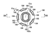
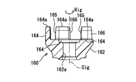
- the joint member 160 is formed of a synthetic resin such as polyphenylene sulfide (PPS) resin, for example, as shown in FIGS. Rotate in the circumferential direction.
- the joint member 160 has a main body portion 162 and a foot portion 164.
- the main body 162 is disposed in an arrangement space 158 formed in the pump cover 112, and is formed in an annular shape having a fitting hole 162a opened at the center, and the rotating shaft 104a is inserted into the fitting hole 162a. Thus, the rotary shaft 104a is fitted and fixed.
- a plurality of leg portions 164 are provided corresponding to the number of insertion holes 127 of the inner gear 120.
- the number of legs 164 is a number that avoids the number of poles and the number of slots of the electric motor 104, and is provided with five prime numbers in particular.
- Each of these foot portions 164 is provided as extending along the axial direction from a plurality of locations (five locations in the present embodiment) on the outer peripheral side of the fitting hole 162a that is a fitting location of the main body portion 162. ing.
- the plurality of legs 164 are arranged at equal intervals in the circumferential direction.
- Each foot 164 can be elastically deformed by a material having elasticity and a shape extending along the axial direction.
- each leg portion 164 is elastically deformed according to the corresponding insertion hole 127, so that a dimensional error in the circumferential direction of each insertion hole 127 and each leg portion 164 that may occur during manufacturing.
- the foot 164 and the insertion hole 127 come into contact with each other while absorbing the water.
- the joint member 160 transmits the driving force of the rotating shaft 104 a to the inner gear 120 through the plurality of legs 164.
- Each such foot 164 is inserted into the corresponding insertion hole 127 with a gap.
- the tip 164a of each foot 164 extends in the axial direction toward the electric motor 104 from the center of gravity of the inner gear 120 with respect to the insertion hole 127 penetrating the inner gear 120 in the axial direction. However, it is extended so as not to reach the outside of the insertion hole 127. Further, the tip 164a of each leg 164 has a guide shape for facilitating assembly at the time of manufacture as shown in FIG.
- Each foot portion 164 has a top portion 165 that faces the flat portion 127a in the circumferential direction.
- the top portion 165 is curved in a convex shape in plan view, and in particular in the present embodiment, is formed in a semi-cylindrical shape having a generatrix along the axial direction.
- Each foot 164 has a reverse apex 166 that faces the reverse flat portion 127b in the circumferential direction.
- the reverse apex portion 166 is curved in a convex shape in plan view, and in particular in the present embodiment, is formed in a semi-cylindrical shape having a generatrix along the axial direction.
- the inner gear 120 has a circumference in accordance with the shapes of the outer peripheral curved portion 127 c and the inner peripheral curved portion 127 d of the insertion hole 127. Curved along the direction.
- the radius of curvature Rvo of the outer peripheral curved portion 127c, the radius of curvature Rvi of the inner peripheral curved portion 127d, the radius of curvature Rf1 of the outer peripheral side of the foot portion 164, and the radius of curvature Rf2 of the inner peripheral side are: , And is set according to the distance to the inner center line Cig.
- the curvature radii Rf1 and Rf2 are set to be larger than the curvature radius Rvi and smaller than the curvature radius Rvo.
- the curvature radii Rvo, Rvi, Rf1, and Rf2 are set substantially equal to the distance to the inner center line Cig, so that the center of curvature is on the inner center line Cig.
- the top portion 165 separates from the flat portion 127a, while the reverse top portion 166 collides with the reverse flat portion 127b and comes into contact. Meanwhile, the inner gear 120 is rotated in the negative direction of the rotational direction Rig in the circumferential direction. Thereafter, when the drive control of the electric motor 104 is started, the reverse top portion 166 is separated from the reverse flat portion 127b, while the top portion 165 collides with the flat portion 127a, and the inner gear 120 is rotated in the circumferential direction while contacting. Rotate to Rig.
- the fuel pump 101 of this embodiment repeatedly sucks fuel into each pump chamber 140 and discharges it from each pump chamber 140 during driving while repeatedly withstanding the collision at the time of startup.
- the joint member 160 having the main body portion 162 fitted to the rotation shaft 104a rotates together with the rotation shaft 104a.
- stretched along the axial direction from the main-body part 162 is inserted in the insertion hole 127 of the inner gear 120 with a clearance gap, the inner gear 120 rotates in the circumferential direction by the relay of the joint member 160.
- the inner wall on the drive rotation side with respect to the foot 164 has a flat portion 127a along the radial direction.
- a top portion 165 that curves in a convex shape in plan view is opposed to the flat portion 127a in the circumferential direction. According to this, even when the contact position or contact angle of the foot part 164 with respect to the insertion hole 127 changes, the driving force transmitted from the joint member 160 to the inner gear 120 when the top part 165 contacts the flat part 127a. Since generation
- the insertion hole 127 has the corner portions 128a to 128b that are adjacent to the flat portion 127a and curved in a concave shape in plan view, and the curvature radius Rc at the corner portions 128a to 128b is It is smaller than the curvature radius Rp1.
- the radius of curvature Rp1 is set, the flat portion 127a can be set wide in the insertion hole 127. Therefore, even if the contact position or the contact angle of the foot portion 164 with respect to the insertion hole 127 changes, the top portion 165 is fixed to the flat portion. 127a can be reliably brought into contact with.
- a plurality of insertion holes 127 having a flat portion 127a are provided, and a foot portion 164 having a top portion 165 extends from a plurality of locations on the outer peripheral side of the fitting hole 162a of the main body portion 162.
- These foot portions 164 are provided so as to be elastically deformable. According to this, even when the foot portion 164 is elastically deformed to the outer peripheral side due to the centrifugal force generated by driving the rotating shaft 104a, the top portion 165 can be reliably brought into contact with the flat portion 127a.
- the plurality of insertion holes 127 and the plurality of legs 164 are arranged at equal intervals in the circumferential direction. By arranging at equal intervals, it is possible to suppress the fluctuation of the driving force due to the rotation phase of the inner gear 120 and the occurrence of pulsation, so that the pump efficiency can be increased.
- the insertion hole 127 has the reverse flat portion 127b along the radial direction on the inner wall on the drive rotation reverse side with respect to the foot portion 164, and the foot portion 164 includes the reverse flat portion 127b. And a reverse apex portion 166 that is curved in a convex shape in plan view. According to this, even when the rotary shaft 104a rotates to the reverse side of the drive rotation due to, for example, positioning control at the time of starting the electric motor 104, the joint member 160 is in contact with the reverse top portion 166 when contacting the reverse flat portion 127b.
- the generation of radial component force in the driving force transmitted from the inner gear 120 to the inner gear 120 is suppressed, and the concentration of the load at a specific location of the joint member 160 can be suppressed. Therefore, the inner gear 120 can be efficiently rotated over a long period of time.
- the foot portion 164 is curved along the circumferential direction
- the insertion hole 127 is a curved portion 127c that is curved along the circumferential direction on the inner wall opposed to the foot portion 164 in the radial direction.
- Has d According to such a curve, when the top portion 165 contacts the flat portion 127a and when the reverse top portion 166 contacts the reverse flat portion 127b, the vertical contact with the flat portion 127a and the reverse flat portion 127b is achieved.
- the top portion 165 and the reverse top portion 166 can be easily brought into contact with each other at an angle or a contact angle close to vertical. Since the curved portions 127c to 127d are curved along the circumferential direction in the same manner as the foot portion 164, the foot portion 164 is difficult to contact the curved portions 127c to 127d.
- the top portion 165 or the inverted top portion 166 is curved in a plan view.
- the radii of curvature Rp1 and Rp2 of the top 165 or the reverse top 166 in plan view may vary depending on the location.
- the radii of curvature Rp1 and Rp2 of the top portion 165 or the reverse top portion 166 in plan view may be different on the inner peripheral side and the outer peripheral side.
- a planar portion 164 b may be provided adjacent to the top portion 165 or the reverse top portion 166.
- the joint member 160 may be provided with the foot 164 so as to be elastically deformable by aluminum other than the synthetic resin, for example.
- the plurality of insertion holes 127 and the plurality of legs 164 may be provided at unequal intervals in the circumferential direction.
- the radius of curvature Rc of the corner portions 128a to 128d may be equal to or larger than the radius of curvature Rp1 at the top portion 165.
- the inner wall facing the foot 164 in the radial direction may be formed in a planar shape.
- the insertion hole 127 may be formed in a bottomed hole shape that does not penetrate to the concave bottom side as long as the insertion hole 127 is recessed along the axial direction.
- the fuel pump 101 may suck and discharge gasoline other than light oil or liquid fuel based thereon as fuel.
Landscapes
- Engineering & Computer Science (AREA)
- Mechanical Engineering (AREA)
- General Engineering & Computer Science (AREA)
- Chemical & Material Sciences (AREA)
- Combustion & Propulsion (AREA)
- Rotary Pumps (AREA)
- Details And Applications Of Rotary Liquid Pumps (AREA)
Abstract
Description
以下、第1実施形態を図面に基づいて説明する。
(第2実施形態)
以下、第2実施形態を図面に基づいて説明する。
Claims (12)
- 内歯(32a)を複数有するアウタギア(30)と、
外歯(24a)を複数有し、前記アウタギア(30)とは偏心方向(De)に偏心して噛合するインナギア(20)と、
前記アウタギア(30)及び前記インナギア(20)を回転可能に収容するポンプハウジング(10)と、
回転駆動する回転軸(4a)を有する電動モータ(4)と、
前記回転軸(4a)を前記インナギア(20)と中継するジョイント部材(60)とを備え、
前記アウタギア(30)及び前記インナギア(20)は、それら両ギア間に複数形成されるポンプ室(40)の容積を拡縮させつつ回転することにより、燃料を各前記ポンプ室(40)に順次吸入してから吐出し、
前記インナギア(20)は、軸方向に沿って凹む挿入穴(27)を有し、
前記ジョイント部材(60)は、
前記回転軸(4a)に嵌合する本体部(62)と、
前記本体部(62)から軸方向に沿って伸び、前記挿入穴(27)に隙間をあけて挿入される足部(64)と、
前記足部(64)から前記インナギア(20)の回転進行側に向かって突出し、頂点部(66a)に向かう程軸方向における幅が狭くなる突出部(66)とを有することを特徴とする燃料ポンプ。 - 前記突出部(66)は、軸方向に曲率を有する湾曲凸面状に突出することを特徴とする請求項1に記載の燃料ポンプ。
- 前記挿入穴(27)は、前記突出部(66)に対して回転進行側となる内周壁(27a)において、径方向に沿った平面部(27b)を有し、
前記突出部(66)は、径方向に沿った母線(Lg)を有する部分円筒面状に突出することを特徴とする請求項1又は2に記載の燃料ポンプ。 - 前記突出部(66)は、前記足部(64)の先端(64a)よりも前記本体部(62)側から突出することを特徴とする請求項1から3のいずれか1項に記載の燃料ポンプ。
- 前記挿入穴(27)は、複数設けられ、
前記足部(64)及び前記突出部(66)は、前記挿入穴(27)に対応して複数設けられることを特徴とする請求項1から4のいずれか1項に記載の燃料ポンプ。 - 前記ジョイント部材(60)は、前記足部(64)から前記インナギア(20)の回転逆側に向かって前記突出部(66)と同様の形状に突出する逆突出部(68)を有することを特徴とする請求項1から5のいずれか1項に記載の燃料ポンプ。
- 内歯(132a)を複数有するアウタギア(130)と、
外歯(124a)を複数有し、前記アウタギア(130)とは偏心方向(De)に偏心して嵌合するインナギア(120)と、
前記アウタギア(130)及び前記インナギア(120)を回転可能に収容するポンプハウジング(110)と、
回転駆動する回転軸(104a)を有する電動モータ(104)と、
前記回転軸(104a)を前記インナギア(120)と中継することで、前記インナギア(120)を周方向に回転させるジョイント部材(160)とを備え、
前記アウタギア(130)及び前記インナギア(120)は、それら両ギア間に複数形成されるポンプ室(140)の容積を拡縮させつつ回転することにより、燃料を各前記ポンプ室(140)に順次吸入してから吐出し、
前記インナギア(120)は、軸方向に沿って凹む挿入穴(127)を有し、
前記ジョイント部材(160)は、
前記回転軸(104a)に嵌合する本体部(162)と、
前記本体部(162)から軸方向に沿って延伸し、前記挿入穴(127)に隙間をあけて挿入される足部(164)とを有し、
前記挿入穴(127)は、前記足部(164)に対して駆動回転側となる内壁において、径方向に沿った平坦部(127a)を有し、
前記足部(164)は、前記平坦部(127a)と前記周方向において対向し、平面視において凸状に湾曲する頂部(165)を有することを特徴とする燃料ポンプ。 - 前記挿入穴(127)は、前記平坦部(127a)に隣接し、平面視において凹状に湾曲するコーナ部(128a~b)を有し、
前記コーナ部(128a~b)における曲率半径(Rc)は、前記頂部(165)における曲率半径(Rp1)よりも小さいことを特徴とする請求項7に記載の燃料ポンプ。 - 前記平坦部(127a)を有する前記挿入穴(127)は、複数設けられ、
前記頂部(165)を有する前記足部(164)は、前記本体部(162)の嵌合箇所(162a)よりも外周側の複数箇所から延伸するものとして複数設けられ、
各前記足部(164)は、弾性変形可能に設けられることを特徴とする請求項7又は8に記載の燃料ポンプ。 - 各前記挿入穴(127)及び各前記足部(164)は、前記周方向に等間隔に配置されることを特徴とする請求項9に記載の燃料ポンプ。
- 前記挿入穴(127)は、前記足部(164)に対して駆動回転逆側となる内壁において、前記径方向に沿った逆平坦部(127b)を有し、
前記足部(164)は、前記逆平坦部(127b)と前記周方向において対向し、平面視において凸状に湾曲する逆頂部(166)を有することを特徴とする請求項7から10のいずれか1項に記載の燃料ポンプ。 - 前記足部(164)は、前記周方向に沿って湾曲し、
前記挿入穴(127)は、前記足部(164)に対して前記径方向において対向する内壁において、前記周方向に沿って湾曲する湾曲部(127c~d)を有することを特徴とする請求項11に記載の燃料ポンプ。
Priority Applications (4)
| Application Number | Priority Date | Filing Date | Title |
|---|---|---|---|
| KR1020177019711A KR101941283B1 (ko) | 2015-01-27 | 2016-01-19 | 연료펌프 |
| CN201680006939.6A CN107250542B (zh) | 2015-01-27 | 2016-01-19 | 燃料泵 |
| DE112016000489.3T DE112016000489T5 (de) | 2015-01-27 | 2016-01-19 | Kraftstoffpumpe |
| US15/544,532 US10883499B2 (en) | 2015-01-27 | 2016-01-19 | Fuel pump including a protruding portion and connecting an inner gear and a rotary shaft |
Applications Claiming Priority (4)
| Application Number | Priority Date | Filing Date | Title |
|---|---|---|---|
| JP2015-013545 | 2015-01-27 | ||
| JP2015013545A JP6500455B2 (ja) | 2015-01-27 | 2015-01-27 | 燃料ポンプ |
| JP2015082662A JP6485182B2 (ja) | 2015-04-14 | 2015-04-14 | 燃料ポンプ |
| JP2015-082662 | 2015-04-14 |
Publications (1)
| Publication Number | Publication Date |
|---|---|
| WO2016121334A1 true WO2016121334A1 (ja) | 2016-08-04 |
Family
ID=56542959
Family Applications (1)
| Application Number | Title | Priority Date | Filing Date |
|---|---|---|---|
| PCT/JP2016/000248 Ceased WO2016121334A1 (ja) | 2015-01-27 | 2016-01-19 | 燃料ポンプ |
Country Status (5)
| Country | Link |
|---|---|
| US (1) | US10883499B2 (ja) |
| KR (1) | KR101941283B1 (ja) |
| CN (1) | CN107250542B (ja) |
| DE (1) | DE112016000489T5 (ja) |
| WO (1) | WO2016121334A1 (ja) |
Cited By (1)
| Publication number | Priority date | Publication date | Assignee | Title |
|---|---|---|---|---|
| CN110462220A (zh) * | 2017-04-07 | 2019-11-15 | 爱三工业株式会社 | 燃料泵 |
Families Citing this family (4)
| Publication number | Priority date | Publication date | Assignee | Title |
|---|---|---|---|---|
| JP6299655B2 (ja) * | 2015-04-14 | 2018-03-28 | 株式会社デンソー | 燃料ポンプ |
| JP6380364B2 (ja) * | 2015-12-17 | 2018-08-29 | 株式会社デンソー | 燃料ポンプ及び燃料ポンプモジュール |
| JP7067505B2 (ja) * | 2019-02-15 | 2022-05-16 | トヨタ自動車株式会社 | 燃料ポンプの診断装置 |
| US12018680B2 (en) * | 2022-04-12 | 2024-06-25 | Phinia Delphi Luxembourg Sarl | Fluid pump with thrust bearing driver |
Citations (3)
| Publication number | Priority date | Publication date | Assignee | Title |
|---|---|---|---|---|
| JPS5795488U (ja) * | 1980-12-01 | 1982-06-11 | ||
| JPH06123288A (ja) * | 1992-10-09 | 1994-05-06 | Nippondenso Co Ltd | ギヤポンプ |
| JPH1113640A (ja) * | 1997-06-19 | 1999-01-19 | Nissan Motor Co Ltd | オイルポンプ構造 |
Family Cites Families (14)
| Publication number | Priority date | Publication date | Assignee | Title |
|---|---|---|---|---|
| US419241A (en) * | 1890-01-14 | Flexible shaft-coupling | ||
| US4613316A (en) * | 1984-10-29 | 1986-09-23 | Barry Wright Corporation | Molded constant velocity coupling |
| AU587222B2 (en) * | 1985-01-28 | 1989-08-10 | Sanden Corporation | Drive system for the orbiting scroll of a scroll type fluid compressor |
| DE3925085C1 (ja) | 1989-07-28 | 1991-01-10 | Battelle-Institut Ev, 6000 Frankfurt, De | |
| US5006048A (en) * | 1989-09-19 | 1991-04-09 | Mingyen Electronics Industry Co., Ltd. | Electrically-operated gear rotor pump |
| US5145348A (en) * | 1991-05-15 | 1992-09-08 | Eaton Corporation | Gerotor pump having an improved drive mechanism |
| JPH0514576U (ja) * | 1991-08-02 | 1993-02-26 | 三菱自動車工業株式会社 | クレセント型内接歯車ポンプ |
| JPH05202861A (ja) * | 1991-10-30 | 1993-08-10 | Nippondenso Co Ltd | 歯車式ポンプ |
| JP2002257052A (ja) * | 2001-03-05 | 2002-09-11 | Denso Corp | トロコイドギヤポンプ |
| US6739850B2 (en) * | 2001-10-25 | 2004-05-25 | Kyosan Denki Co., Ltd. | Motor-type fuel pump for vehicle |
| GB0308957D0 (en) * | 2003-04-17 | 2003-05-28 | Lillishall Plastics And Engine | Tolerance ring assembly |
| US7722344B2 (en) | 2006-11-15 | 2010-05-25 | Airtex Products, Llc | Impeller-drive shaft construction for a fuel pump |
| DE102007049704B4 (de) * | 2007-10-17 | 2019-01-31 | Robert Bosch Gmbh | Innenzahnradpumpe für eine Bremsanlage |
| TWI510715B (zh) * | 2009-09-25 | 2015-12-01 | Ulvac Inc | 真空乾式泵浦 |
-
2016
- 2016-01-19 CN CN201680006939.6A patent/CN107250542B/zh not_active Expired - Fee Related
- 2016-01-19 KR KR1020177019711A patent/KR101941283B1/ko not_active Expired - Fee Related
- 2016-01-19 WO PCT/JP2016/000248 patent/WO2016121334A1/ja not_active Ceased
- 2016-01-19 US US15/544,532 patent/US10883499B2/en not_active Expired - Fee Related
- 2016-01-19 DE DE112016000489.3T patent/DE112016000489T5/de not_active Withdrawn
Patent Citations (3)
| Publication number | Priority date | Publication date | Assignee | Title |
|---|---|---|---|---|
| JPS5795488U (ja) * | 1980-12-01 | 1982-06-11 | ||
| JPH06123288A (ja) * | 1992-10-09 | 1994-05-06 | Nippondenso Co Ltd | ギヤポンプ |
| JPH1113640A (ja) * | 1997-06-19 | 1999-01-19 | Nissan Motor Co Ltd | オイルポンプ構造 |
Cited By (1)
| Publication number | Priority date | Publication date | Assignee | Title |
|---|---|---|---|---|
| CN110462220A (zh) * | 2017-04-07 | 2019-11-15 | 爱三工业株式会社 | 燃料泵 |
Also Published As
| Publication number | Publication date |
|---|---|
| KR20170098253A (ko) | 2017-08-29 |
| CN107250542B (zh) | 2020-04-03 |
| KR101941283B1 (ko) | 2019-01-22 |
| US10883499B2 (en) | 2021-01-05 |
| DE112016000489T5 (de) | 2017-11-02 |
| US20180010606A1 (en) | 2018-01-11 |
| CN107250542A (zh) | 2017-10-13 |
Similar Documents
| Publication | Publication Date | Title |
|---|---|---|
| US8944784B2 (en) | Compressor and motor device thereof | |
| WO2016121334A1 (ja) | 燃料ポンプ | |
| CN107002676B (zh) | 电动涡旋压缩机 | |
| JP6459740B2 (ja) | 流体ポンプ | |
| JP5622033B2 (ja) | 流体ポンプ | |
| CN112112952B (zh) | 一种由主减齿轮驱动的机械油泵 | |
| JP6418094B2 (ja) | 燃料ポンプ | |
| JP6105280B2 (ja) | 電動オイルポンプ | |
| US9841019B2 (en) | Fuel pump with a joint member having a leg inserted into an insertion hole of an inner gear | |
| JP6361561B2 (ja) | 流体ポンプ | |
| JP6299655B2 (ja) | 燃料ポンプ | |
| JP6350294B2 (ja) | 燃料ポンプ | |
| JP6500587B2 (ja) | 燃料ポンプ | |
| JP6485182B2 (ja) | 燃料ポンプ | |
| US20160333875A1 (en) | Fuel pump | |
| JP5740223B2 (ja) | 一軸偏心ねじポンプ | |
| JP6430557B2 (ja) | 電動オイルポンプ | |
| JP2024107634A (ja) | ロータおよびポンプ装置 | |
| JP6500455B2 (ja) | 燃料ポンプ | |
| JP6418059B2 (ja) | 燃料ポンプ | |
| JP2025134381A (ja) | 流体機械 | |
| WO2023176170A1 (ja) | オイルポンプ | |
| JP2021038798A (ja) | 増速機 | |
| WO2019189114A1 (ja) | 電動ポンプおよびトルク伝達装置 | |
| WO2016103663A1 (ja) | 燃料ポンプ |
Legal Events
| Date | Code | Title | Description |
|---|---|---|---|
| 121 | Ep: the epo has been informed by wipo that ep was designated in this application |
Ref document number: 16742939 Country of ref document: EP Kind code of ref document: A1 |
|
| ENP | Entry into the national phase |
Ref document number: 20177019711 Country of ref document: KR Kind code of ref document: A |
|
| WWE | Wipo information: entry into national phase |
Ref document number: 15544532 Country of ref document: US |
|
| WWE | Wipo information: entry into national phase |
Ref document number: 112016000489 Country of ref document: DE |
|
| 122 | Ep: pct application non-entry in european phase |
Ref document number: 16742939 Country of ref document: EP Kind code of ref document: A1 |