WO2016117310A1 - 車載制御装置、携帯端末、およびプログラム製品 - Google Patents
車載制御装置、携帯端末、およびプログラム製品 Download PDFInfo
- Publication number
- WO2016117310A1 WO2016117310A1 PCT/JP2016/000174 JP2016000174W WO2016117310A1 WO 2016117310 A1 WO2016117310 A1 WO 2016117310A1 JP 2016000174 W JP2016000174 W JP 2016000174W WO 2016117310 A1 WO2016117310 A1 WO 2016117310A1
- Authority
- WO
- WIPO (PCT)
- Prior art keywords
- vehicle
- position information
- time interval
- current location
- control device
- Prior art date
- Legal status (The legal status is an assumption and is not a legal conclusion. Google has not performed a legal analysis and makes no representation as to the accuracy of the status listed.)
- Ceased
Links
Images


Classifications
-
- G—PHYSICS
- G01—MEASURING; TESTING
- G01C—MEASURING DISTANCES, LEVELS OR BEARINGS; SURVEYING; NAVIGATION; GYROSCOPIC INSTRUMENTS; PHOTOGRAMMETRY OR VIDEOGRAMMETRY
- G01C21/00—Navigation; Navigational instruments not provided for in groups G01C1/00 - G01C19/00
- G01C21/26—Navigation; Navigational instruments not provided for in groups G01C1/00 - G01C19/00 specially adapted for navigation in a road network
-
- G—PHYSICS
- G01—MEASURING; TESTING
- G01C—MEASURING DISTANCES, LEVELS OR BEARINGS; SURVEYING; NAVIGATION; GYROSCOPIC INSTRUMENTS; PHOTOGRAMMETRY OR VIDEOGRAMMETRY
- G01C21/00—Navigation; Navigational instruments not provided for in groups G01C1/00 - G01C19/00
- G01C21/26—Navigation; Navigational instruments not provided for in groups G01C1/00 - G01C19/00 specially adapted for navigation in a road network
- G01C21/28—Navigation; Navigational instruments not provided for in groups G01C1/00 - G01C19/00 specially adapted for navigation in a road network with correlation of data from several navigational instruments
-
- G—PHYSICS
- G09—EDUCATION; CRYPTOGRAPHY; DISPLAY; ADVERTISING; SEALS
- G09B—EDUCATIONAL OR DEMONSTRATION APPLIANCES; APPLIANCES FOR TEACHING, OR COMMUNICATING WITH, THE BLIND, DEAF OR MUTE; MODELS; PLANETARIA; GLOBES; MAPS; DIAGRAMS
- G09B29/00—Maps; Plans; Charts; Diagrams, e.g. route diagram
- G09B29/10—Map spot or coordinate position indicators; Map reading aids
Definitions
- the present disclosure relates to a portable terminal, an in-vehicle control device, and a program product that realizes route guidance provided in a vehicle occupant that realizes route guidance in cooperation in a navigation system.
- a positioning function provided in, for example, a navigation device for a vehicle one using satellite navigation using a satellite positioning system such as GPS (Global Positioning System) or autonomous navigation using an inertial sensor is known (for example, , See Patent Document 1).
- a form of use has been proposed in which a navigation function by an application implemented on a mobile terminal such as a so-called smart phone is linked with an in-vehicle control device to present route guidance information provided by the mobile terminal to the user through the in-vehicle control device.
- a mobile terminal provided in a vehicle occupant is connected to a vehicle-mounted control device by wireless or wired communication, and route guidance information generated by a navigation function of the mobile terminal is transmitted to the vehicle-mounted control device.
- the in-vehicle control device displays or voices the route guidance information transmitted from the mobile terminal using a display or a speaker mounted on the vehicle.
- the vehicle-mounted control device is responsible for the information presentation function
- the portable terminal is responsible for the navigation-related processing function including positioning of the current location of the vehicle.
- the mobile terminal measures the current location using a GPS receiver provided in the mobile terminal.
- the GPS receiver provided in the mobile terminal receives a navigation signal at intervals of 1 second in the normal state and measures the current location, but the time interval for positioning can be changed as necessary. This makes it possible to perform control such as shortening the time interval for positioning when precise position information is required for route guidance at an appropriate timing, such as branch guidance near an intersection. It is done.
- the positioning accuracy can be improved by shortening the time interval for positioning in the mobile terminal
- the processing load of the arithmetic processing device for positioning increases, which may hinder the operation of other applications.
- the GPS receiver provided in the mobile terminal has a reception performance that is not as good as that outside the vehicle when the mobile terminal is placed in the vehicle, and there is a possibility that the position information necessary for route guidance cannot be obtained sufficiently.
- An object of the present invention is to provide an in-vehicle control device, a portable terminal, and a program product for enabling acquisition of position information of the current location of the vehicle at intervals.
- a first aspect of the present disclosure includes a mobile terminal that performs route guidance processing based on received position information, and an in-vehicle control device that presents a user with route guidance information generated by the route guidance processing by the mobile terminal.
- the present invention relates to an in-vehicle control device constituting a system.
- This in-vehicle control device includes a positioning unit, a transmission unit, and a determination unit.
- the positioning unit measures the current location of the vehicle.
- the transmission unit periodically transmits position information representing the current location measured by the positioning unit to the portable terminal at a predetermined time interval.
- the determination unit determines a time interval for transmitting the position information according to the location of the road corresponding to the current location, based on given road map information representing the road map.
- the transmission unit transmits the position information at the time interval determined by the determination unit.
- the position information indicating the current location of the vehicle measured by the in-vehicle control device is transmitted to the mobile terminal, and the mobile terminal performs route guidance processing using the position information, thereby reducing the processing load on the mobile terminal side. it can. Furthermore, the in-vehicle control device sets the transmission interval of the position information according to the location of the road corresponding to the current location, for example, by shortening the time interval for transmitting the position information in a situation where high-precision positioning is required. Can change. By doing in this way, it is possible to accurately acquire position information of the current location at time intervals according to road conditions.
- a second aspect of the present disclosure is a navigation including a mobile terminal that performs route guidance processing based on received position information, and an in-vehicle control device that presents the route guidance information generated by the route guidance processing by the mobile terminal to a user.
- the present invention relates to a mobile terminal constituting the system.
- the portable terminal includes a receiving unit, a determining unit, and a requesting unit.
- the receiving unit receives position information transmitted from the vehicle-mounted control device at regular intervals. Based on given road map information representing the road map, the determination unit transmits the position information according to the location of the road corresponding to the current location of the vehicle represented by the position information received by the reception unit. Determine the time interval. The request unit requests the in-vehicle control device to transmit the position information at the time interval determined by the determination unit.
- the position information is transmitted according to the location of the road corresponding to the current location of the vehicle, for example, by shortening the time interval for transmitting the position information in a situation where high-precision positioning is required.
- the transmission interval can be appropriately determined and requested to the in-vehicle control device.
- the in-vehicle control device transmits the position information to the mobile terminal at a time interval requested from the mobile terminal, thereby reducing the processing load for the mobile terminal to measure the current location, and at the time interval according to the situation. It is possible to accurately acquire the position information.
- a portable terminal having a function of receiving position information representing the current location of a vehicle and performing route guidance processing based on the received position information, and a route generated by route guidance processing by the portable terminal
- the present invention relates to a program product executed by a mobile terminal that constitutes a navigation system having an in-vehicle control device having a function of presenting guidance information to a user.
- This program product receives position information periodically transmitted from the in-vehicle control device at a predetermined time interval, and based on given road map information representing a road map, the current location represented by the received position information.
- the processing load of the mobile terminal is reduced, and the location information of the current location of the vehicle at time intervals according to the situation Can be obtained.
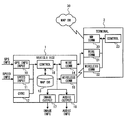
- FIG. 1 is a block diagram illustrating a configuration of a navigation system according to an embodiment of the present disclosure.
- FIG. 2 is a flowchart showing the procedure of the current location update process.
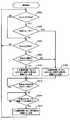
- FIG. 3 is a flowchart showing a procedure of transmission time determination processing according to the first embodiment of the present disclosure.
- FIG. 4 is a flowchart showing a procedure of transmission time determination processing according to the second embodiment of the present disclosure.
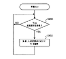
- FIG. 5 is a flowchart illustrating a procedure of a transmission time change process according to the second embodiment of the present disclosure.
- the navigation system includes an in-vehicle ECU (Electronic Control Unit) 1 mounted on a vehicle and a mobile terminal 2 carried by a vehicle occupant as an example of the in-vehicle control device.
- ECU Electronic Control Unit
- the in-vehicle ECU 1 is an electronic control device that forms a corner of a video / audio output system mounted on a vehicle.
- the in-vehicle ECU 1 includes a GPS information input unit (GPS INPUT) 10, a vehicle speed input unit (SPEED INPUT) 11, a gyro sensor (GYRO) 12, a map information database (MAP DB) 13, a wired communication unit (WIRE COM) 14, and a short distance
- GPS INPUT GPS information input unit
- SPEED INPUT vehicle speed input unit
- GYRO gyro sensor
- MAP DB map information database
- WIRE COM wireless communication unit
- a wireless communication unit (WIRELESS COMM) 15 a control unit (CONTROL) 16
- IMAGE OUTPUT image output unit
- AUDIO OUTPUT audio output unit
- the GPS information input unit 10 is an input interface for inputting GPS information (GPS INFO) received from navigation satellites used in GPS to the control unit 16.
- the vehicle speed input unit 11 is an input interface for inputting vehicle speed information (SPEED INFO) detected by a vehicle speed sensor of the host vehicle.
- the gyro sensor 12 is an inertial sensor that detects the angular velocity of the host vehicle.
- the map information database 13 is a storage device that stores map data in which information about road maps is written.
- the map data stored in the map information database 13 includes information indicating the connection status of roads by the nodes corresponding to intersections, branch points, road shape points, and road links connecting the nodes.
- the wired communication unit 14 is a communication module that connects the in-vehicle ECU 1 and the mobile terminal 2 via a communication line and performs wired communication.
- the wired communication unit 14 is exemplified by applying a communication method compliant with a general-purpose bus standard such as USB (Universal Serial Bus).
- the short-range wireless communication unit 15 is a communication module that performs short-range wireless communication with the mobile terminal 2.
- the short-range wireless communication unit 15 is exemplified by applying a communication method based on a communication standard such as Bluetooth (registered trademark) or Wi-Fi (registered trademark).
- the control unit 16 is an information processing device mainly configured with a CPU, a ROM, a RAM, an input / output interface and the like (not shown), and controls the operation of the in-vehicle ECU 1.
- the control unit 16 executes various processes related to vehicle route guidance based on given programs and data.
- the control unit 16 has a function of controlling the output of image information and audio information based on the route guidance information received from the mobile terminal 2.
- the control unit 16 executes various processes such as a current location update process, a transmission time determination process (first embodiment), and a transmission time change process (second embodiment) which will be described later.
- the image output unit 17 is an output interface that outputs the image information (IMAGE INFO) supplied from the control unit 16 to a display (not shown) mounted on the vehicle and displays it.
- the audio output unit 18 is an output interface that outputs the audio information (AUDIO INFO) supplied from the control unit 16 to a speaker (not shown) mounted on the vehicle and outputs this as audio.
- the mobile terminal (TERMINAL) 2 is a mobile information terminal such as a so-called smartphone having both functions of a mobile phone and a personal computer.
- the mobile terminal 2 includes a network communication unit (NW COMM) 20, a wired communication unit (WIRE COMM) 21, a short-range wireless communication unit (WIRELESS COMM) 22, and a control unit (CONTROL) 23.
- NW COMM network communication unit
- WIRE COMM wired communication unit
- WIRELESS COMM short-range wireless communication unit
- CONTROL control unit
- the network communication unit 20 is a communication interface for connecting to the Internet via a mobile phone network or a wireless public LAN (Local Area Network).
- the mobile terminal 2 is connected to the Internet via the network communication unit 20 and accesses a map information database 30 composed of an external server device connected to the Internet.
- the map information database 30 stores map data in which information about road maps necessary for route guidance processing is written. This map data includes road data indicating road connection status by road links connecting nodes and nodes corresponding to intersections, branch points, road shape points, and drawing data necessary for displaying map images, etc. Is included.
- the wired communication unit 21 is a communication module that connects the mobile terminal 2 and the vehicle-mounted ECU 1 via a communication line to perform wired communication.
- the wired communication unit 21 is exemplified by applying a communication method conforming to a general-purpose bus standard such as USB (Universal Serial Bus), like the wired communication unit 14 of the in-vehicle ECU 1.
- the short-range wireless communication unit 22 is a communication module that performs short-range wireless communication with the in-vehicle ECU 1. As the short-range wireless communication unit 22, similarly to the short-range wireless communication unit 15 of the in-vehicle ECU 1, it is exemplified that a communication method compliant with a communication standard such as Bluetooth or Wi-Fi is applied.
- the control unit 23 is an arithmetic processing device that includes a CPU, ROM, RAM, input interface, and the like (not shown), and performs overall control of the operation of the mobile terminal 2.
- the control unit 23 executes various applications according to a given program. In the present embodiment, a route guidance process for performing route guidance from the current location of the vehicle to the destination is assumed as an application executed by the control unit 23. In addition, the control unit 23 executes various processes such as a current location update process and a transmission time determination process (second embodiment) described later.
- Examples of the contents of the route guidance processing executed by the control unit 23 include map display and travel guidance. Based on the position information representing the current location, the control unit 23 generates image information representing a map image in which a map around the current location acquired from the map information database 30 and a mark indicating the current location are superimposed. Further, the control unit 23 uses the map data acquired from the map information database 30 to search for the optimum route from the current location to the destination. Then, using the obtained optimum route as a guidance route, image information for displaying the guidance route in a superimposed manner on a map image is generated. And the control part 23 produces
- the control unit 23 transmits route guidance information including image information and voice information representing the map and guidance information generated in the route guidance process to the in-vehicle ECU 1 via the wired communication unit 21 or the short-range wireless communication unit 22. Since other functions and configurations of the mobile terminal 2 are in accordance with known techniques, detailed description thereof is omitted here.
- the navigation system of the present embodiment is configured to present information related to route guidance to the driver when the in-vehicle ECU 1 and the portable terminal 2 cooperate with each other.
- the in-vehicle ECU 1 measures the current location, and periodically transmits position information indicating the current location to the mobile terminal 2.
- the mobile terminal 2 updates the current location as a reference for route guidance processing based on the position information received from the in-vehicle ECU 1. By doing in this way, the burden that the portable terminal 2 performs positioning based on GPS information is reduced.
- the in-vehicle ECU 1 can measure the current location using not only GPS information but also vehicle speed information and a measurement value obtained by the gyro sensor 12, the mobile terminal 2 can obtain more accurate position information than the mobile terminal 2 itself. can get.
- the mobile terminal 2 executes the route guidance process described above based on the position information received from the in-vehicle ECU 1. And the portable terminal 2 transmits the route guidance information which consists of image information and audio
- the in-vehicle ECU 1 causes the display to display image information related to the route guidance based on the route guidance information received from the mobile terminal 2, and causes the speaker to output audio information.
- the procedure of the current location update process executed by the control unit 16 of the in-vehicle ECU 1 and the control unit 23 of the mobile terminal 2 will be described based on the flowchart of FIG.
- This process is periodically executed at a time interval (Ti) determined in a transmission time determination process of the first embodiment or the second embodiment described later.
- the current location update processing is executed at intervals of 1 second in normal time, and at a time interval shorter than normal time (100 milliseconds or 200 milliseconds) under conditions where the current location corresponds to a specific road section. Executed.
- the control unit 16 of the in-vehicle ECU 1 determines the current location of the host vehicle based on the measurement values and map information input from the GPS information input unit 10, the vehicle speed input unit 11, the gyro sensor 12, and the map information database 13. Positioning. For positioning of the current location, it is conceivable to use satellite navigation based on GPS information, autonomous navigation based on vehicle speed information or measured values of the gyro sensor 12, or the like.
- the control unit 16 of the in-vehicle ECU 1 transmits position information representing the current location measured in S ⁇ b> 100 to the mobile terminal 2 via the wired communication unit 14 or the short-range wireless communication unit 15.
- control unit 23 of the mobile terminal 2 acquires the position information transmitted from the in-vehicle ECU 1.
- control unit 23 of the mobile terminal 2 updates the current location stored in the memory based on the position information received in S104.
- the transmission time determination process according to the first embodiment will be described with reference to the flowchart of FIG.
- the control part 16 of vehicle-mounted ECU1 repeatedly performs with a predetermined control period.
- the map information database 13 can be used in the in-vehicle ECU 1.
- the control unit 16 determines that the distance (Dcurv) from the current location to the road section corresponding to the curve existing ahead of the planned route is 200 m or less. It is determined whether or not there is. Specifically, the control unit 16 calculates the distance to the curve ahead of the course along the planned route set by the route guidance process by the mobile terminal 2 using the map data around the current location. Further, even when there is no scheduled route set in the route guidance process, if there is a curve that inevitably enters along the running road, the distance to the curve is determined. When the curve does not exist within 200 m from the current location (S200: NO), the control unit 16 proceeds to S204. On the other hand, when the distance from the current location to the curve is 200 m or less (S200: YES), the control unit 16 proceeds to S202.
- the control unit 16 determines whether or not the curve determined in S200 corresponds to a specific curve.
- the specific curve here is, for example, a shape corresponding to a condition that is a target of curve guidance (warning) in the route guidance processing.
- the control unit 16 proceeds to S208.
- the control unit 16 proceeds to S204.
- the control unit 16 determines whether or not the distance (Dints) from the current location to the intersection ahead of the planned route is 200 m or less. Specifically, the control unit 16 calculates the distance to the intersection ahead of the course along the planned route set by the route guidance process by the mobile terminal 2 using the map data around the current location. Even if there is no scheduled route set in the route guidance process, if there is an intersection that inevitably enters along the traveling road, the distance to the intersection is determined. When there is no intersection within 200 m from the current location (S204: NO), the control unit 16 returns to S200. On the other hand, when the distance from the current location to the intersection is 200 m or less (S204: YES), the control unit 16 proceeds to S206.
- the control unit 16 determines whether or not the type of the intersection determined in S204 is a roundabout (circular intersection). When the intersection is not a roundabout (S206: NO), the control unit 16 proceeds to S208. On the other hand, when the intersection is a roundabout (S206: YES), the control unit 16 proceeds to S210.
- the control unit 16 changes the time interval (Ti) for transmitting the position information indicating the current location to the mobile terminal 2 from 1 second, which is the standard time, to 200 milliseconds.
- the control unit 16 changes the time interval (Ti) for transmitting the position information representing the current location to the mobile terminal 2 from 1 second, which is the standard time, to 100 milliseconds.
- the control unit 16 determines whether or not there is a current location in the curve section determined in S200 or in the intersection determined in S204.
- the control unit 16 repeats the process of S212.
- the control unit 16 proceeds to S214.
- the control unit 16 determines whether or not the vehicle has passed 100 m or more after passing through the curve section determined in S200 or the intersection determined in S204. When the own vehicle has not passed 100 m or more from the curve section or the intersection (S214: NO), the control unit 16 repeats the process of S214. On the other hand, when the vehicle passes 100 m or more after passing through the curve section or the intersection (S214: YES), the control unit 16 proceeds to S216. In S216, the control unit 16 returns the time interval (Ti) for transmitting the position information indicating the current location to the portable terminal 2 to 1 second which is the standard time. After S216, the control unit 16 returns to S200.
- Ti time interval
- the control part 23 of the portable terminal 2 differs from the above-mentioned 1st Embodiment in the point which performs the transmission time determination process.
- the control unit 23 of the portable terminal 2 repeatedly executes the transmission time determination process at a predetermined control cycle. Therefore, in 2nd Embodiment, the map information database 13 does not necessarily need to be mounted in vehicle-mounted ECU1.
- the control unit 23 determines that the distance (Dcurv) from the current location to the road section corresponding to the curve existing ahead of the planned route is 200 m or less. It is determined whether or not there is. Specifically, the control unit 23 calculates the distance to the curve ahead of the course along the planned route set in the route guidance process using the map data around the current location. Further, even when there is no scheduled route set in the route guidance process, if there is a curve that inevitably enters along the running road, the distance to the curve is determined. When the curve does not exist within 200 m from the current location (S300: NO), the control unit 23 proceeds to S304. On the other hand, when the distance from the current location to the curve is 200 m or less (S300: YES), the control unit 23 proceeds to S302.
- the control unit 23 determines whether or not the curve determined in S300 corresponds to a specific curve.
- the specific curve here is, for example, a shape corresponding to a condition that is a target of curve guidance (warning) in the route guidance processing.
- the control unit 23 proceeds to S308.
- the control unit 23 proceeds to S304.
- the control unit 23 determines whether or not the distance (Dints) from the current location to the intersection ahead of the planned route is 200 m or less. Specifically, the control unit 23 calculates the distance to the intersection ahead of the course along the planned route set in the route guidance process using the map data around the current location. Even if there is no scheduled route set in the route guidance process, if there is an intersection that inevitably enters along the traveling road, the distance to the intersection is determined. When there is no intersection within 200 m from the current location (S304: NO), the control unit 23 returns to S300. On the other hand, when the distance from the current location to the intersection is 200 m or less (S304: YES), the control unit 23 proceeds to S306.
- control unit 23 determines whether or not the type of the intersection determined in S304 is a roundabout (circular intersection). When the intersection is not a roundabout (S306: NO), the control unit 23 proceeds to S308. On the other hand, when the intersection is a roundabout (S306: YES), the control unit 23 proceeds to S310.
- the control unit 23 transmits to the in-vehicle ECU 1 a change request for changing the time interval (Ti) for transmitting the position information indicating the current location from 1 second which is the standard time to 200 milliseconds.
- the control unit 23 transmits to the in-vehicle ECU 1 a change request for changing the time interval (Ti) for transmitting the position information indicating the current location from 1 second which is the standard time to 100 milliseconds.
- the wired communication unit 21 or the short-range wireless communication unit 22 that has established communication connection with the in-vehicle ECU 1 is used.
- the control unit 23 determines whether or not there is a current location in the curve section determined in S300 or in the intersection determined in S304. When there is a present location within the curve section or the intersection (S312: YES), the control unit 23 repeats the process of S312. On the other hand, when the present location is out of the curve section or the intersection (S312: NO), the control unit 23 proceeds to S314.
- the control unit 23 determines whether or not the current location is at a position where 100 m or more has passed after passing through the curve section determined in S300 or the intersection determined in S304. When the present location has not passed 100 m or more from the curve section or the intersection (S314: NO), the control unit 23 repeats the process of S314. On the other hand, when the current location is at a position where 100 m or more has passed after passing through the curve section or the intersection (S314: YES), the control unit 23 proceeds to S316.
- the control unit 23 transmits to the in-vehicle ECU 1 a change request for returning the time interval (Ti) for transmitting the position information indicating the current location to 1 second which is the standard time.
- the wired communication unit 21 or the short-range wireless communication unit 22 that has established communication connection with the in-vehicle ECU 1 is used.
- the control unit 23 returns to S300.
- the control unit 16 determines whether or not the request for changing the time interval (Ti) for transmitting the position information has been received from the portable terminal 2.
- the time interval change request is transmitted from the portable terminal 2 to the in-vehicle ECU 1 in S308, S310, or S316 of the transmission time determination process (see the second embodiment, FIG. 4).
- the control unit 16 repeats the process of S400.
- the control unit 16 proceeds to S402.
- the control unit 16 changes the time interval for transmitting position information indicating the current location according to the content of the change request received from the mobile terminal 2. After S402, the control unit 16 returns to S400.
- the GPS information input unit 10 the vehicle speed input unit 11, the gyro sensor 12, and the control unit 16 function as a positioning unit
- 16 functions as a transmission unit
- the control unit 16 functions as a determination unit.
- the wired communication unit 21, the short-range wireless communication unit 22, and the control unit 23 function as a reception unit, and the control unit 23 functions as a determination unit and a request unit.
- the present disclosure uses a portable terminal having a function of receiving position information indicating the current location of a vehicle and performing route guidance processing based on the received position information, and route guidance information generated by route guidance processing by the portable terminal.
- the program may be provided as a program or a program product for executing the above control by a portable terminal or an in-vehicle control device constituting a navigation system having an in-vehicle control device having a function to be presented to a user.
- the navigation system according to the present disclosure has the following effects.
- the position information representing the current location measured by the in-vehicle ECU 1 is transmitted to the mobile terminal 2, and the mobile terminal 2 performs route guidance processing using the position information, thereby reducing the processing load on the mobile terminal 2 side.
- the in-vehicle ECU 1 changes the position information transmission interval according to the location of the road corresponding to the current location, such as shortening the time interval for transmitting the position information in the vicinity of the intersection or the curve.
- the mobile terminal 2 requests the in-vehicle ECU 1 to change the transmission interval of the position information according to the location of the road corresponding to the current location.
Landscapes
- Engineering & Computer Science (AREA)
- Radar, Positioning & Navigation (AREA)
- Remote Sensing (AREA)
- Automation & Control Theory (AREA)
- Physics & Mathematics (AREA)
- General Physics & Mathematics (AREA)
- Navigation (AREA)
- Instructional Devices (AREA)
Abstract
車両の現在地を表す位置情報を受信し、この位置情報に基づいて経路案内処理を行う機能を備える携帯端末(2)と、携帯端末による経路案内処理で生成された経路案内情報を利用者に提示する機能を備える車載制御装置(1)とを有するナビゲーションシステムを構成する車載制御装置は、車両の現在地を測位する測位部(10,11,12,16)と、測位された車両の現在地を表す位置情報を、決められた時間間隔で定期的に携帯端末に送信する送信部(14,15,16)と、道路地図を表す所与の道路地図情報に基づき、現在地に該当する道路の場所に応じて、位置情報を送信する時間間隔を決定する決定部(16)と、を備え、送信部は、決定部により決定された時間間隔で位置情報を送信する。
Description
本出願は、2015年1月21日に出願された日本特許出願番号2015-009549号に基づくもので、ここにその記載内容を援用する。
本開示は、ナビゲーションシステムにおいて、連携して経路案内を実現する車両の乗員が備える携帯端末と車載制御装置及び経路案内を実現するプログラム製品に関する。
従来、例えば車両用のナビゲーション装置等に備えられる測位機能として、GPS(Global Positioning System)等の衛星測位システムを用いる衛星航法や、慣性センサを用いる自律航法を利用するものが知られている(例えば、特許文献1参照)。
近年、いわゆるスマートフォン等の携帯端末に実装されたアプリケーションによるナビゲーション機能と車載制御装置とを連携させることで、携帯端末が提供する経路案内情報を、車載制御装置を通じてユーザに提示するといった利用形態が提案されている。具体的には、車両の乗員が備える携帯端末を無線や有線により車載制御装置に通信接続し、携帯端末のナビゲーション機能により生成される経路案内情報を車載制御装置に送信する。
車載制御装置は、携帯端末から送信されてくる経路案内情報を、車両に搭載されているディスプレイやスピーカを用いて表示や音声出力する。このような利用形態においては、車載制御装置が情報提示機能を担い、携帯端末が、車両の現在地の測位を含むナビゲーションに関する処理機能を担っている。このような実施形態において、携帯端末は、自己が備えるGPS受信機を用いて現在地を測位する。
携帯端末に備えられたGPS受信機は、例えば通常状態において1秒間隔で航法信号を受信して現在地を測位するが、必要に応じて測位を行う時間間隔を変えることが可能となっている。これにより、例えば交差点付近での分岐案内のように、的確なタイミングで経路案内を行うために精密な位置情報が必要となるときに、測位を行う時間間隔を短くするといった制御を行うことが考えられる。
しかしながら、携帯端末において測位を行う時間間隔を短くすることで測位精度を向上できる反面、測位にかかる演算処理装置の処理負荷が高くなることで、他のアプリケーションの動作に支障をきたすおそれがある。また、携帯端末に備えられたGPS受信機は、携帯端末が車内に置かれた状態では受信性能が車外ほど良好ではなく、経路案内に必要な位置情報を十分に得られないおそれがある。
本開示は、上記点に鑑みてなされたものであり、携帯端末と車載制御装置とが連携して経路案内を実現するシステムにおいて、携帯端末の処理負荷を軽減し、かつ、状況に応じた時間間隔で車両の現在地の位置情報を取得可能にするための車載制御装置、携帯端末、およびプログラム製品を提供することを目的とする。
本開示の第1態様は、受信した位置情報に基づいて経路案内処理を行う携帯端末と、携帯端末による経路案内処理で生成された経路案内情報を利用者に提示する車載制御装置とを有するナビゲーションシステムを構成する車載制御装置に関する。この車載制御装置は、測位部と、送信部と、決定部とを備える。
測位部は、車両の現在地を測位する。送信部は、測位部により測位された現在地を表す位置情報を、決められた時間間隔で定期的に携帯端末に送信する。決定部は、道路地図を表す所与の道路地図情報に基づき、現在地に該当する道路の場所に応じて、位置情報を送信する時間間隔を決定する。送信部は、決定部により決定された時間間隔で位置情報を送信する。
本開示では、車載制御装置が測位した車両の現在地を表す位置情報を携帯端末に送信し、その位置情報を利用して携帯端末が経路案内処理を行うことで、携帯端末側の処理負荷を軽減できる。さらに、車載制御装置は、現在地に該当する道路の場所に応じて、例えば、精度の高い測位が必要とされる状況において位置情報を送信する時間間隔を短くするといった具合に位置情報の送信間隔を変更できる。このようにすることで、道路の状況に応じた時間間隔で現在地の位置情報を的確に取得可能にすることができる。
本開示の第2態様は、受信した位置情報に基づいて経路案内処理を行う携帯端末と、携帯端末による経路案内処理で生成された経路案内情報を利用者に提示する車載制御装置とを有するナビゲーションシステムを構成する携帯端末に関する。この携帯端末は、受信部と、決定部と、要求部とを備える。
受信部は、決められた時間間隔で定期的に車載制御装置から送信される位置情報を受信する。決定部は、道路地図を表す所与の道路地図情報に基づき、受信部により受信された位置情報で表される車両の現在地に該当する道路の場所に応じて、車載制御装置が位置情報を送信する時間間隔を決定する。要求部は、車載制御装置に対して、決定部により決定された時間間隔で位置情報を送信するように要求する。
上記携帯端末によれば、車両の現在地に該当する道路の場所に応じて、例えば、精度の高い測位が必要とされる状況において位置情報を送信する時間間隔を短くするといった具合に、位置情報の送信間隔を適宜決定して車載制御装置に要求できる。そして、車載制御装置が、携帯端末から要求された時間間隔で位置情報を携帯端末に送信することで、携帯端末が現在地を測位する処理負荷を軽減し、かつ、状況に応じた時間間隔で現在地の位置情報を的確に取得可能にすることができる。
本開示の第3態様は、車両の現在地を表す位置情報を受信し、その受信した位置情報に基づいて経路案内処理を行う機能を備える携帯端末と、携帯端末による経路案内処理で生成された経路案内情報を利用者に提示する機能を備える車載制御装置とを有するナビゲーションシステムを構成する携帯端末が実行するプログラム製品に関する。このプログラム製品は、決められた時間間隔で定期的に車載制御装置から送信される位置情報を受信し、道路地図を表す所与の道路地図情報に基づき、受信された位置情報で表される現在地に該当する道路の場所に応じて、車載制御装置が位置情報を送信する時間間隔を決定する決定し、車載制御装置に対して、決定された時間間隔で位置情報を送信するように要求するためのコンピュータによって実施される命令を含み、コンピュータ読み取り可能な持続的且つ有形の記憶媒体に保管されている。
上記プログラム製品によれば、携帯端末と車載制御装置とが連携して経路案内を実現するシステムにおいて、携帯端末の処理負荷を軽減し、かつ、状況に応じた時間間隔で車両の現在地の位置情報を取得可能である。
本開示についての上記目的およびその他の目的、特徴や利点は、添付の図面を参照しながら下記の詳細な記述により、より明確になる。その図面は、
図1は、本開示の一実施形態によるナビゲーションシステムの構成を表すブロック図であり、
図2は、現在地更新処理の手順を表すフローチャートであり、
図3は、本開示の第1実施形態による送信時間決定処理の手順を表すフローチャートであり、
図4は、本開示の第2実施形態による送信時間決定処理の手順を表すフローチャートであり、
図5は、本開示の第2実施形態による送信時間変更処理の手順を表すフローチャートである。
以下、本開示の実施形態を図面に基づいて説明する。なお、本開示は下記の実施形態に限定されるものではなく様々な態様にて実施することが可能である。
図1に示すとおり、実施形態のナビゲーションシステムは、車載制御装置の一例として、車両に搭載された車載ECU(Electronic Control Unit)1と、車両の乗員が携帯する携帯端末2とを有する。
車載ECU1は、車両に搭載された映像音声出力システムの一角をなす電子制御装置である。車載ECU1は、GPS情報入力部(GPS INPUT)10、車速入力部(SPEED INPUT)11、ジャイロセンサ(GYRO)12、地図情報データベース(MAP DB)13、有線通信部(WIRE COMM)14、近距離無線通信部(WIRELESS COMM)15、制御部(CONTROL)16、画像出力部(IMAGE OUTPUT)17、及び音声出力部(AUDIO OUTPUT)18を備える。
GPS情報入力部10は、GPSで用いられる航法衛星から受信したGPS情報(GPS INFO)を制御部16に入力するための入力インタフェースである。車速入力部11は、自車両の車速センサにより検出された車速情報(SPEED INFO)を入力するための入力インタフェースである。ジャイロセンサ12は、自車両の角速度を検出する慣性センサである。
地図情報データベース13は、道路地図に関する情報が記された地図データを格納する記憶装置である。地図情報データベース13に格納されている地図データには、交差点や分岐点、道路の形状点に対応する各ノード及びノード間を接続する道路のリンクによる道路の接続状況を表す情報等が含まれる。
有線通信部14は、通信線を介して車載ECU1と携帯端末2とを接続し、有線通信を行う通信モジュールである。この有線通信部14には、例えば、USB(Universal Serial Bus)等の汎用のバス規格に準拠した通信方式を適用することが例示される。近距離無線通信部15は、携帯端末2との間で近距離無線通信を行う通信モジュールである。この近距離無線通信部15には、例えば、Bluetooth(登録商標)やWi‐Fi(登録商標)等の通信規格に準拠した通信方式を適用することが例示される。
制御部16は、図示しないCPU、ROM、RAM、入出力インタフェース等を中心に構成された情報処理装置であり、車載ECU1の動作を制御する。制御部16は、所与のプログラムやデータに基づいて車両の経路案内に関する各種処理を実行する。この制御部16は、携帯端末2から受信した経路案内情報に基づく画像情報や音声情報の出力を制御する機能を有する。また、制御部16は、後述の現在地更新処理、送信時間決定処理(第1実施形態)、送信時間変更処理(第2実施形態)等の各種処理を実行する。
画像出力部17は、制御部16から供給された画像情報(IMAGE INFO)を車両に搭載されたディスプレイ(不図示)に出力し、これを表示させる出力インタフェースである。音声出力部18は、制御部16から供給された音声情報(AUDIO INFO)を車両に搭載されたスピーカ(不図示)に出力し、これを音声として出力させる出力インタフェースである。
携帯端末(TERMINAL)2は、携帯電話とパソコンの機能とを併せ持つ、いわゆるスマートフォン等の携帯情報端末である。携帯端末2は、ネットワーク通信部(NW COMM)20、有線通信部(WIRE COMM)21、近距離無線通信部(WIRELESS COMM)22、及び制御部(CONTROL)23を備える。
ネットワーク通信部20は、携帯電話網や無線公衆LAN(Local Area Network)を介してインターネットに接続するための通信インタフェースである。携帯端末2は、ネットワーク通信部20を介してインターネットに接続し、インターネットに接続された外部のサーバ装置で構成される地図情報データベース30にアクセスする。この地図情報データベース30には、経路案内処理に必要な道路地図に関する情報が記された地図データが格納されている。この地図データには、交差点や分岐点、道路の形状点に対応する各ノード及びノード間を接続する道路のリンクによって道路の接続状況を表す道路データ、及び地図画像の表示に必要な描画データ等が含まれる。
有線通信部21は、通信線を介して携帯端末2と車載ECU1とを接続し、有線通信を行う通信モジュールである。この有線通信部21には、車載ECU1の有線通信部14と同様に、USB(Universal Serial Bus)等の汎用のバス規格に準拠した通信方式を適用することが例示される。近距離無線通信部22は、車載ECU1との間で近距離無線通信を行う通信モジュールである。この近距離無線通信部22には、車載ECU1の近距離無線通信部15と同様に、BluetoothやWi‐Fi等の通信規格に準拠した通信方式を適用することが例示される。
制御部23は、図示しないCPU、ROM、RAM、入力インタフェース等を備えた演算処理装置であり、携帯端末2の動作を統括制御する。制御部23は、所与のプログラムに従って、種々のアプリケーションを実行する。本実施形態では、制御部23が実行するアプリケーションとして、車両の現在地から目的までの経路案内を行う経路案内処理を想定している。また、制御部23は、後述の現在地更新処理、送信時間決定処理(第2実施形態)等の各種処理を実行する。
制御部23が実行する経路案内処理の内容としては、地図表示や走行案内が例示される。制御部23は、現在地を表す位置情報に基づいて、地図情報データベース30から取得した現在地周辺の地図と現在地を示すマークとを重ね合わせた地図画像を表す画像情報を生成する。また、制御部23は、地図情報データベース30から取得した地図データを用いて、現在地から目的地までの最適経路を探索する。そして、得られた最適経路を誘導経路として、その誘導経路を地図画像上に重ね合わせて表示させるための画像情報を生成する。そして、制御部23は、現在地の推移に伴って、経路上の分岐点やカーブ等の特定の案内ポイントの手前で、進行方向や注意喚起等の案内情報を表す画像情報や音声情報を生成する。
制御部23は、経路案内処理において生成された地図や案内情報を表す画像情報及び音声情報からなる経路案内情報を、有線通信部21又は近距離無線通信部22を介して車載ECU1に送信する。なお、携帯端末2の他の機能や構成については公知技術に従っているので、ここでの詳細な説明は省略する。
本実施形態のナビゲーションシステムは、車載ECU1と携帯端末2とが連携することにより、運転者に対して経路案内に関する情報を提示する構成となっている。具体的には、車載ECU1が現在地の測位を行い、測位した現在地を表す位置情報を周期的に携帯端末2に送信する。携帯端末2は、車載ECU1から受信した位置情報に基づいて、経路案内処理の基準となる現在地を更新する。このようにすることで、携帯端末2がGPS情報に基づいて測位をする負担を軽減している。また、車載ECU1では、GPS情報だけでなく、車速情報やジャイロセンサ12による測定値を利用して現在地を測位することができるので、携帯端末2が自ら現在地を測位するよりも正確な位置情報を得られる。
携帯端末2は、車載ECU1から受信した位置情報に基づいて上述の経路案内処理を実行する。そして、携帯端末2は、経路案内処理の結果として生成された画像情報や音声情報からなる経路案内情報を車載ECU1に送信する。車載ECU1は、携帯端末2から受信した経路案内情報に基づいて、経路案内に関する画像情報をディスプレイに表示させ、また、音声情報をスピーカに出力させる。
車載ECU1の制御部16及び携帯端末2の制御部23が実行する現在地更新処理の手順について、図2のフローチャートに基づいて説明する。この処理は、後述の第1実施形態又は第2実施形態の送信時間決定処理において決定される時間間隔(Ti)で周期的に実行される。具体的には、現在地更新処理は、通常時においては1秒間隔で実行され、現在地が特定の道路区間に該当する条件下において、通常時より短い時間間隔(100ミリ秒又は200ミリ秒)で実行される。
S100では、車載ECU1の制御部16は、GPS情報入力部10、車速入力部11、ジャイロセンサ12、及び地図情報データベース13の各部から入力された測定値や地図情報に基づいて、自車両の現在地を測位する。現在地の測位には、GPS情報に基づく衛星航法や、車速情報やジャイロセンサ12の測定値に基づく自律航法等を用いることが考えられる。S102では、車載ECU1の制御部16は、S100で測位した現在地を表す位置情報を、有線通信部14又は近距離無線通信部15を介して携帯端末2に送信する。
S104では、携帯端末2の制御部23は、車載ECU1から送信された位置情報を取得する。S106では、携帯端末2の制御部23は、S104で受信した位置情報に基づいて、メモリに記憶している現在地を更新する。
第1実施形態による送信時間決定処理について、図3のフローチャートを参照しながら説明する。第1実施形態の送信時間決定処理については、車載ECU1の制御部16が所定の制御周期で繰返し実行する。その前提として、車載ECU1において地図情報データベース13が利用可能であるものとする。
S200では、制御部16は、地図情報データベース13から読み込んだ現在地周辺の地図データに基づき、現在地から走行予定の進路前方に存在するカーブに該当する道路区間までの距離(Dcurv)が、200m以下であるか否かを判定する。具体的には、制御部16は、現在地周辺の地図データを用いて、携帯端末2による経路案内処理により設定された予定経路に沿って進路前方のカーブまでの距離を算出する。また、経路案内処理において設定された予定経路がない場合であっても、走行中の道路に沿って必然的に進入するカーブがあれば、そのカーブまでの距離を判定する。現在地から200m以内にカーブが存在しない場合(S200:NO)、制御部16はS204に進む。一方、現在地からカーブまでの距離が200m以下である場合(S200:YES)、制御部16はS202に進む。
S202では、制御部16は、S200において判定されたカーブが特定のカーブに該当するか否かを判定する。ここでいう特定のカーブとは、例えば、経路案内処理におけるカーブ案内(警告)の対象となる条件に該当する形状のものである。S200において判定されたカーブが特定のカーブに該当する場合(S202:YES)、制御部16はS208に進む。一方、S200において判定されたカーブが特定のカーブに該当しない場合(S202:NO)、制御部16はS204に進む。
S204では、制御部16は、現在地周辺の地図データに基づき、現在地から走行予定の進路前方に存在する交差点までの距離(Dints)が、200m以下であるか否かを判定する。具体的には、制御部16は、現在地周辺の地図データを用いて、携帯端末2による経路案内処理により設定された予定経路に沿って進路前方の交差点までの距離を算出する。また、経路案内処理において設定された予定経路がない場合であっても、走行中の道路に沿って必然的に進入する交差点があれば、その交差点までの距離を判定する。現在地から200m以内に交差点が存在しない場合(S204:NO)、制御部16はS200に戻る。一方、現在地から交差点までの距離が200m以下である場合(S204:YES)、制御部16はS206に進む。
S206では、制御部16は、S204において判定された交差点の種別がラウンドアバウト(環状交差点)であるか否かを判定する。交差点がラウンドアバウトでない場合(S206:NO)、制御部16はS208に進む。一方、交差点がラウンドアバウトである場合(S206:YES)、制御部16はS210に進む。
S208では、制御部16は、現在地を表す位置情報を携帯端末2に送信する時間間隔(Ti)を、標準時間である1秒から200ミリ秒に変更する。一方、S210では、制御部16は、現在地を表す位置情報を携帯端末2に送信する時間間隔(Ti)を、標準時間である1秒から100ミリ秒に変更する。
次のS212では、制御部16は、S200で判定されたカーブ区間内、又はS204で判定された交差点内に現在地があるか否かを判定する。前記カーブ区間内又は前記交差点内に現在地がある場合(S212:YES)、制御部16はS212の処理を繰返す。一方、現在地が前記カーブ区間内又は前記交差点内から外れている場合(S212:NO)、制御部16はS214に進む。
S214では、制御部16は、S200で判定されたカーブ区間、又はS204で判定された交差点を自車両が通過して100m以上経過したか否かを判定する。自車両が前記カーブ区間又は前記交差点から100m以上経過していない場合(S214:NO)、制御部16はS214の処理を繰返す。一方、自車両が前記カーブ区間又は前記交差点を通過して100m以上経過した場合(S214:YES)、制御部16はS216に進む。S216では、制御部16は、現在地を表す位置情報を携帯端末2に送信する時間間隔(Ti)を、標準時間である1秒に戻す。S216の後、制御部16はS200に戻る。
第2実施形態による送信時間決定処理について、図4のフローチャートを参照しながら説明する。第2実施形態では、携帯端末2の制御部23が送信時間決定処理を実行する点において上述の第1実施形態と異なる。携帯端末2の制御部23は、所定の制御周期で送信時間決定処理を繰返し実行する。したがって、第2実施形態においては、車載ECU1に地図情報データベース13が必ずしも搭載されていなくてもよい。
S300では、制御部23は、地図情報データベース30から取得した現在地周辺の地図データに基づき、現在地から走行予定の進路前方に存在するカーブに該当する道路区間までの距離(Dcurv)が、200m以下であるか否かを判定する。具体的には、制御部23は、現在地周辺の地図データを用いて、経路案内処理において設定された予定経路に沿って進路前方のカーブまでの距離を算出する。また、経路案内処理において設定された予定経路がない場合であっても、走行中の道路に沿って必然的に進入するカーブがあれば、そのカーブまでの距離を判定する。現在地から200m以内にカーブが存在しない場合(S300:NO)、制御部23はS304に進む。一方、現在地からカーブまでの距離が200m以下である場合(S300:YES)、制御部23はS302に進む。
S302では、制御部23は、S300において判定されたカーブが特定のカーブに該当するか否かを判定する。ここでいう特定のカーブとは、例えば、経路案内処理におけるカーブ案内(警告)の対象となる条件に該当する形状のものである。S300において判定されたカーブが特定のカーブに該当する場合(S302:YES)、制御部23はS308に進む。一方、S300において判定されたカーブが特定のカーブに該当しない場合(S302:NO)、制御部23はS304に進む。
S304では、制御部23は、現在地周辺の地図データに基づき、現在地から走行予定の進路前方に存在する交差点までの距離(Dints)が、200m以下であるか否かを判定する。具体的には、制御部23は、現在地周辺の地図データを用いて、経路案内処理において設定された予定経路に沿って進路前方の交差点までの距離を算出する。また、経路案内処理において設定された予定経路がない場合であっても、走行中の道路に沿って必然的に進入する交差点があれば、その交差点までの距離を判定する。現在地から200m以内に交差点が存在しない場合(S304:NO)、制御部23はS300に戻る。一方、現在地から交差点までの距離が200m以下である場合(S304:YES)、制御部23はS306に進む。
S306では、制御部23は、S304において判定された交差点の種別がラウンドアバウト(環状交差点)であるか否かを判定する。交差点がラウンドアバウトでない場合(S306:NO)、制御部23はS308に進む。一方、交差点がラウンドアバウトである場合(S306:YES)、制御部23はS310に進む。
S308では、制御部23は、現在地を表す位置情報を送信する時間間隔(Ti)を、標準時間である1秒から200ミリ秒に変更する変更要求を、車載ECU1に送信する。一方、S310では、制御部23は、現在地を表す位置情報を送信する時間間隔(Ti)を、標準時間である1秒から100ミリ秒に変更する変更要求を、車載ECU1に送信する。なお、送信には、有線通信部21又は近距離無線通信部22のうち、車載ECU1との通信接続が確立しているものを使う。
次のS312では、制御部23は、S300で判定されたカーブ区間内、又はS304で判定された交差点内に現在地があるか否かを判定する。前記カーブ区間内又は前記交差点内に現在地がある場合(S312:YES)、制御部23はS312の処理を繰返す。一方、現在地が前記カーブ区間内又は前記交差点内から外れている場合(S312:NO)、制御部23はS314に進む。
S314では、制御部23は、現在地がS300で判定されたカーブ区間、又はS304で判定された交差点を通過して100m以上経過した位置にあるか否かを判定する。現在地が前記カーブ区間又は前記交差点から100m以上経過していない場合(S314:NO)、制御部23はS314の処理を繰返す。一方、現在地が前記カーブ区間又は前記交差点を通過して100m以上経過した位置にある場合(S314:YES)、制御部23はS316に進む。
S316では、制御部23は、現在地を表す位置情報を送信する時間間隔(Ti)を標準時間である1秒に戻す変更要求を、車載ECU1に送信する。なお、送信には、有線通信部21又は近距離無線通信部22のうち、車載ECU1との通信接続が確立しているものを使う。S316の後、制御部23はS300に戻る。
第2実施形態の送信時間決定処理(図4参照)に対応して、車載ECU1の制御部16が実行する送信時間変更処理の手順について、図5のフローチャートを参照しながら説明する。この送信時間変更処理は、所定の制御間隔で繰返し実行される。
S400では、制御部16は、位置情報を送信する時間間隔(Ti)の変更要求を携帯端末2から受信したか否かを判定する。時間間隔の変更要求については、上述の送信時間決定処理(第2実施形態、図4参照)のS308、S310、又はS316において、携帯端末2から車載ECU1に送信される。時間間隔の変更要求を受信していない場合(S400:NO)、制御部16はS400の処理を繰返す。
一方、時間間隔の変更要求を受信している場合(S400:YES)、制御部16はS402に進む。S402では、制御部16は、携帯端末2から受信した変更要求の内容に従って、現在地を表す位置情報を送信する時間間隔を変更する。S402の後、制御部16はS400に戻る。
本開示による車載制御装置1において、GPS情報入力部10、車速入力部11、ジャイロセンサ12、及び制御部16が測位部として機能し、有線通信部14、近距離無線通信部15、及び制御部16が送信部として機能し、制御部16が決定部として機能する。
また、携帯端末2において、有線通信部21、近距離無線通信部22、及び制御部23が受信部として機能し、制御部23が決定部及び要求部として機能する。
本開示は、車両の現在地を表す位置情報を受信し、その受信した位置情報に基づいて経路案内処理を行う機能を備える携帯端末と、携帯端末による経路案内処理で生成された経路案内情報を利用者に提示する機能を備える車載制御装置とを有するナビゲーションシステムを構成する携帯端末又は車載制御装置により上記制御を実行するためのプログラム、又はプログラム製品として提供されてもよい。
本開示のナビゲーションシステムによれば次の効果を奏する。
車載ECU1が測位した現在地を表す位置情報を携帯端末2に送信し、その位置情報を利用して携帯端末2が経路案内処理を行うことで、携帯端末2側の処理負荷を軽減できる。また、第1実施形態では、交差点付近やカーブ付近において位置情報を送信する時間間隔を短くするといった具合に、現在地に該当する道路の場所に応じて、車載ECU1が位置情報の送信間隔を変更する。一方、第2実施形態では、現在地に該当する道路の場所に応じて、携帯端末2が位置情報の送信間隔の変更を車載ECU1に要求する。このようにすることで、交差点やカーブ等の道路の状況に応じた時間間隔で現在地の位置情報を的確に取得可能にすることができる。
本開示は、実施例に準拠して記述されたが、本開示は当該実施例や構造に限定されるものではないと理解される。本開示は、様々な変形例や均等範囲内の変形をも包含する。加えて、様々な組み合わせや形態、さらには、それらに一要素のみ、それ以上、あるいはそれ以下、を含む他の組み合わせや形態をも、本開示の範畴や思想範囲に入るものである。
Claims (9)
- 車両の現在地を表す位置情報を受信し、その受信した位置情報に基づいて経路案内処理を行う機能を備える携帯端末(2)と、前記携帯端末による経路案内処理で生成された経路案内情報を利用者に提示する機能を備える車載制御装置とを有するナビゲーションシステムを構成する前記車載制御装置であって、
前記車両の現在地を測位する測位部(10,11,12,16)と、
前記測位部(10,11,12,16)により測位された車両の現在地を表す位置情報を、決められた時間間隔で定期的に前記携帯端末に送信する送信部(14,15,16)と、
道路地図を表す所与の道路地図情報に基づき、前記現在地に該当する道路の場所に応じて、前記位置情報を送信する時間間隔を決定する決定部(16)とを備え、
前記送信部(14,15,16)は、前記決定部(16)により決定された時間間隔で前記位置情報を送信する車載制御装置。 - 車両の現在地を表す位置情報を受信し、その受信した位置情報に基づいて経路案内処理を行う機能を備える携帯端末と、前記携帯端末による経路案内処理で生成された経路案内情報を利用者に提示する機能を備える車載制御装置(1)とを有するナビゲーションシステムを構成する前記携帯端末であって、
決められた時間間隔で定期的に前記車載制御装置から送信される位置情報を受信する受信部(21,22,23)と、
道路地図を表す所与の道路地図情報に基づき、前記受信部により受信された位置情報で表される前記車両の現在地に該当する道路の場所に応じて、前記車載制御装置が前記位置情報を送信する時間間隔を決定する決定部(23)と、
前記車載制御装置に対して、前記決定部により決定された時間間隔で前記位置情報を送信するように要求する要求部(23)とを備える携帯端末。 - 請求項1に記載の車載制御装置において、
前記決定部(16)は、通行予定の交差点を基準とする所定範囲に前記現在地が該当する場合、前記時間間隔を所定の基準値よりも短く決定する車載制御装置。 - 請求項3に記載の車載制御装置において、
前記決定部(16)は、通行予定の交差点を基準とする所定範囲に前記現在地が該当する場合、当該交差点の種別ごとに異なる時間間隔を決定する車載制御装置。 - 請求項2に記載の携帯端末において、
前記決定部(23)は、通行予定の交差点を基準とする所定範囲に前記現在地が該当する場合、前記時間間隔を所定の基準値よりも短く決定する携帯端末。 - 請求項5に記載の携帯端末において、
前記決定部(23)は、通行予定の交差点を基準とする所定範囲に前記現在地が該当する場合、当該交差点の種別ごとに異なる時間間隔を決定する携帯端末。 - 請求項1、請求項3、又は請求項4の何れか1項に記載の車載制御装置において、
前記決定部(16)は、通行予定の道路において特定の線形を有する箇所を基準とする所定範囲に前記現在地が該当する場合、前記時間間隔を所定の基準値よりも短く決定する車載制御装置。 - 請求項2、請求項5、又は請求項6の何れか1項に記載の携帯端末において、
前記決定部(23)は、通行予定の道路において特定の線形を有する箇所を基準とする所定範囲に前記現在地が該当する場合、前記時間間隔を所定の基準値よりも短く決定する携帯端末。 - 車両の現在地を表す位置情報を受信し、その受信した位置情報に基づいて経路案内処理を行う機能を備える携帯端末と、前記携帯端末による経路案内処理で生成された経路案内情報を利用者に提示する機能を備える車載制御装置とを有するナビゲーションシステムを構成する前記携帯端末が実行するプログラム製品であって、
決められた時間間隔で定期的に前記車載制御装置から送信される位置情報を受信し(S104)、
道路地図を表す所与の道路地図情報に基づき、前記受信された位置情報で表される前記車両の現在地に該当する道路の場所に応じて、前記車載制御装置が前記位置情報を送信する時間間隔を決定し(S302,S306)、
前記車載制御装置に対して、前記決定された時間間隔で前記位置情報を送信するように要求する(S308,S310,S312)
ためのコンピュータによって実施される命令を含み、コンピュータ読み取り可能な持続的且つ有形の記憶媒体に保管されているプログラム製品。
Applications Claiming Priority (2)
| Application Number | Priority Date | Filing Date | Title |
|---|---|---|---|
| JP2015-009549 | 2015-01-21 | ||
| JP2015009549A JP2016133451A (ja) | 2015-01-21 | 2015-01-21 | 車載制御装置、携帯端末、プログラム |
Publications (1)
| Publication Number | Publication Date |
|---|---|
| WO2016117310A1 true WO2016117310A1 (ja) | 2016-07-28 |
Family
ID=56416865
Family Applications (1)
| Application Number | Title | Priority Date | Filing Date |
|---|---|---|---|
| PCT/JP2016/000174 Ceased WO2016117310A1 (ja) | 2015-01-21 | 2016-01-15 | 車載制御装置、携帯端末、およびプログラム製品 |
Country Status (2)
| Country | Link |
|---|---|
| JP (1) | JP2016133451A (ja) |
| WO (1) | WO2016117310A1 (ja) |
Families Citing this family (3)
| Publication number | Priority date | Publication date | Assignee | Title |
|---|---|---|---|---|
| DE112017003424T5 (de) | 2016-07-05 | 2019-03-28 | Shin-Etsu Polymer Co., Ltd. | Kapazitiver dreidimensionaler sensor |
| WO2018225116A1 (ja) * | 2017-06-05 | 2018-12-13 | エヴィクサー株式会社 | ナビゲーションシステム |
| CN111752254A (zh) * | 2019-03-28 | 2020-10-09 | 深圳市商汤科技有限公司 | 轨迹跟踪控制器的测试方法、装置、介质及设备 |
Citations (6)
| Publication number | Priority date | Publication date | Assignee | Title |
|---|---|---|---|---|
| JP2003207351A (ja) * | 2002-01-16 | 2003-07-25 | Matsushita Electric Ind Co Ltd | ナビゲーション装置 |
| JP2004184174A (ja) * | 2002-12-02 | 2004-07-02 | Alpine Electronics Inc | 車載用ナビゲーション装置 |
| JP2004340633A (ja) * | 2003-05-13 | 2004-12-02 | Hitachi Ltd | ナビゲーションの機能を有する携帯電話、および、ナビゲーションの機能を有する携帯電話を使用するナビゲーション方法 |
| JP2009122079A (ja) * | 2007-11-19 | 2009-06-04 | Fujitsu Ten Ltd | 測位システムおよび車載装置 |
| JP2010130670A (ja) * | 2008-12-01 | 2010-06-10 | Fujitsu Ten Ltd | 車載システム |
| US20130245880A1 (en) * | 2012-03-14 | 2013-09-19 | Zonar Systems, Inc. | Event based gps tracking |
-
2015
- 2015-01-21 JP JP2015009549A patent/JP2016133451A/ja active Pending
-
2016
- 2016-01-15 WO PCT/JP2016/000174 patent/WO2016117310A1/ja not_active Ceased
Patent Citations (6)
| Publication number | Priority date | Publication date | Assignee | Title |
|---|---|---|---|---|
| JP2003207351A (ja) * | 2002-01-16 | 2003-07-25 | Matsushita Electric Ind Co Ltd | ナビゲーション装置 |
| JP2004184174A (ja) * | 2002-12-02 | 2004-07-02 | Alpine Electronics Inc | 車載用ナビゲーション装置 |
| JP2004340633A (ja) * | 2003-05-13 | 2004-12-02 | Hitachi Ltd | ナビゲーションの機能を有する携帯電話、および、ナビゲーションの機能を有する携帯電話を使用するナビゲーション方法 |
| JP2009122079A (ja) * | 2007-11-19 | 2009-06-04 | Fujitsu Ten Ltd | 測位システムおよび車載装置 |
| JP2010130670A (ja) * | 2008-12-01 | 2010-06-10 | Fujitsu Ten Ltd | 車載システム |
| US20130245880A1 (en) * | 2012-03-14 | 2013-09-19 | Zonar Systems, Inc. | Event based gps tracking |
Also Published As
| Publication number | Publication date |
|---|---|
| JP2016133451A (ja) | 2016-07-25 |
Similar Documents
| Publication | Publication Date | Title |
|---|---|---|
| JP6283393B2 (ja) | 運転手支援システム及び衝突を回避する方法 | |
| JP5304882B2 (ja) | 車載情報処理装置及び情報処理方法 | |
| JP6143474B2 (ja) | 位置検出装置およびプログラム | |
| KR20100059911A (ko) | 특성 포인트에 의한 차량 위치의 보정 | |
| JPWO2018225596A1 (ja) | 情報処理装置 | |
| JP2013246038A (ja) | 車両用現在位置決定装置 | |
| US8989997B2 (en) | Map display system, method, and program | |
| JP2008256620A (ja) | 地図データ修正装置、地図データ修正方法、及び地図データ修正プログラム | |
| WO2016117310A1 (ja) | 車載制御装置、携帯端末、およびプログラム製品 | |
| JP6123556B2 (ja) | 車両認証システム | |
| CN108701410A (zh) | 车辆用通信控制装置 | |
| JP2015005113A (ja) | 判定装置、受信装置、制御方法、プログラム、及び記憶媒体 | |
| JP4573287B2 (ja) | ナビゲーションシステム | |
| JP4420034B2 (ja) | 車両用地図表示装置 | |
| JP6410596B2 (ja) | 情報処理装置、プログラム | |
| JP2007071665A (ja) | ナビゲーションシステム | |
| JP4409968B2 (ja) | ナビゲーション装置の経路誘導方法、およびナビゲーション装置 | |
| JP2009282832A (ja) | 車載装置および渋滞通報システム | |
| JP5895815B2 (ja) | 残距離算出装置、残距離算出方法及び運転支援装置 | |
| KR20120067228A (ko) | 차선인식수단을 이용한 차량용 항법지도의 갱신장치 | |
| JP2013120186A (ja) | 位置情報処理装置および位置情報処理方法 | |
| JP2020041936A (ja) | ナビゲーション方法及びナビゲーション装置 | |
| JP2006157746A (ja) | 車載通信端末装置 | |
| JP7145712B2 (ja) | 地図データのダウンロード方法及び地図記録装置 | |
| KR101236110B1 (ko) | 모바일 기기를 이용한 내비게이션 정보 업데이트 방법 및 모바일 기기를 이용한 내비게이션 정보 업데이트 시스템 |
Legal Events
| Date | Code | Title | Description |
|---|---|---|---|
| 121 | Ep: the epo has been informed by wipo that ep was designated in this application |
Ref document number: 16739921 Country of ref document: EP Kind code of ref document: A1 |
|
| NENP | Non-entry into the national phase |
Ref country code: DE |
|
| 122 | Ep: pct application non-entry in european phase |
Ref document number: 16739921 Country of ref document: EP Kind code of ref document: A1 |