WO2016117307A1 - 孔開け加工装置 - Google Patents
孔開け加工装置 Download PDFInfo
- Publication number
- WO2016117307A1 WO2016117307A1 PCT/JP2016/000171 JP2016000171W WO2016117307A1 WO 2016117307 A1 WO2016117307 A1 WO 2016117307A1 JP 2016000171 W JP2016000171 W JP 2016000171W WO 2016117307 A1 WO2016117307 A1 WO 2016117307A1
- Authority
- WO
- WIPO (PCT)
- Prior art keywords
- valve seat
- nozzle body
- debris
- laser
- suction
- Prior art date
- Legal status (The legal status is an assumption and is not a legal conclusion. Google has not performed a legal analysis and makes no representation as to the accuracy of the status listed.)
- Ceased
Links
Images








Classifications
-
- B—PERFORMING OPERATIONS; TRANSPORTING
- B23—MACHINE TOOLS; METAL-WORKING NOT OTHERWISE PROVIDED FOR
- B23B—TURNING; BORING
- B23B29/00—Holders for non-rotary cutting tools; Boring bars or boring heads; Accessories for tool holders
- B23B29/03—Boring heads
- B23B29/034—Boring heads with tools moving radially, e.g. for making chamfers or undercuttings
-
- B—PERFORMING OPERATIONS; TRANSPORTING
- B23—MACHINE TOOLS; METAL-WORKING NOT OTHERWISE PROVIDED FOR
- B23K—SOLDERING OR UNSOLDERING; WELDING; CLADDING OR PLATING BY SOLDERING OR WELDING; CUTTING BY APPLYING HEAT LOCALLY, e.g. FLAME CUTTING; WORKING BY LASER BEAM
- B23K26/00—Working by laser beam, e.g. welding, cutting or boring
- B23K26/16—Removal of by-products, e.g. particles or vapours produced during treatment of a workpiece
-
- B—PERFORMING OPERATIONS; TRANSPORTING
- B23—MACHINE TOOLS; METAL-WORKING NOT OTHERWISE PROVIDED FOR
- B23B—TURNING; BORING
- B23B51/00—Tools for drilling machines
- B23B51/04—Drills for trepanning
- B23B51/0486—Drills for trepanning with lubricating or cooling equipment
- B23B51/0493—Drills for trepanning with lubricating or cooling equipment with exchangeable cutting inserts, e.g. able to be clamped
-
- B—PERFORMING OPERATIONS; TRANSPORTING
- B23—MACHINE TOOLS; METAL-WORKING NOT OTHERWISE PROVIDED FOR
- B23K—SOLDERING OR UNSOLDERING; WELDING; CLADDING OR PLATING BY SOLDERING OR WELDING; CUTTING BY APPLYING HEAT LOCALLY, e.g. FLAME CUTTING; WORKING BY LASER BEAM
- B23K26/00—Working by laser beam, e.g. welding, cutting or boring
- B23K26/02—Positioning or observing the workpiece, e.g. with respect to the point of impact; Aligning, aiming or focusing the laser beam
- B23K26/03—Observing, e.g. monitoring, the workpiece
-
- B—PERFORMING OPERATIONS; TRANSPORTING
- B23—MACHINE TOOLS; METAL-WORKING NOT OTHERWISE PROVIDED FOR
- B23K—SOLDERING OR UNSOLDERING; WELDING; CLADDING OR PLATING BY SOLDERING OR WELDING; CUTTING BY APPLYING HEAT LOCALLY, e.g. FLAME CUTTING; WORKING BY LASER BEAM
- B23K26/00—Working by laser beam, e.g. welding, cutting or boring
- B23K26/08—Devices involving relative movement between laser beam and workpiece
- B23K26/0823—Devices involving rotation of the workpiece
-
- B—PERFORMING OPERATIONS; TRANSPORTING
- B23—MACHINE TOOLS; METAL-WORKING NOT OTHERWISE PROVIDED FOR
- B23K—SOLDERING OR UNSOLDERING; WELDING; CLADDING OR PLATING BY SOLDERING OR WELDING; CUTTING BY APPLYING HEAT LOCALLY, e.g. FLAME CUTTING; WORKING BY LASER BEAM
- B23K26/00—Working by laser beam, e.g. welding, cutting or boring
- B23K26/08—Devices involving relative movement between laser beam and workpiece
- B23K26/083—Devices involving movement of the workpiece in at least one axial direction
- B23K26/0853—Devices involving movement of the workpiece in at least two axial directions, e.g. in a plane
-
- B—PERFORMING OPERATIONS; TRANSPORTING
- B23—MACHINE TOOLS; METAL-WORKING NOT OTHERWISE PROVIDED FOR
- B23K—SOLDERING OR UNSOLDERING; WELDING; CLADDING OR PLATING BY SOLDERING OR WELDING; CUTTING BY APPLYING HEAT LOCALLY, e.g. FLAME CUTTING; WORKING BY LASER BEAM
- B23K26/00—Working by laser beam, e.g. welding, cutting or boring
- B23K26/36—Removing material
- B23K26/38—Removing material by boring or cutting
- B23K26/382—Removing material by boring or cutting by boring
- B23K26/389—Removing material by boring or cutting by boring of fluid openings, e.g. nozzles, jets
-
- B—PERFORMING OPERATIONS; TRANSPORTING
- B23—MACHINE TOOLS; METAL-WORKING NOT OTHERWISE PROVIDED FOR
- B23K—SOLDERING OR UNSOLDERING; WELDING; CLADDING OR PLATING BY SOLDERING OR WELDING; CUTTING BY APPLYING HEAT LOCALLY, e.g. FLAME CUTTING; WORKING BY LASER BEAM
- B23K26/00—Working by laser beam, e.g. welding, cutting or boring
- B23K26/36—Removing material
- B23K26/40—Removing material taking account of the properties of the material involved
-
- B—PERFORMING OPERATIONS; TRANSPORTING
- B23—MACHINE TOOLS; METAL-WORKING NOT OTHERWISE PROVIDED FOR
- B23K—SOLDERING OR UNSOLDERING; WELDING; CLADDING OR PLATING BY SOLDERING OR WELDING; CUTTING BY APPLYING HEAT LOCALLY, e.g. FLAME CUTTING; WORKING BY LASER BEAM
- B23K37/00—Auxiliary devices or processes, not specially adapted for a procedure covered by only one of the other main groups of this subclass
- B23K37/04—Auxiliary devices or processes, not specially adapted for a procedure covered by only one of the other main groups of this subclass for holding or positioning work
- B23K37/0426—Fixtures for other work
- B23K37/0435—Clamps
- B23K37/0443—Jigs
-
- F—MECHANICAL ENGINEERING; LIGHTING; HEATING; WEAPONS; BLASTING
- F02—COMBUSTION ENGINES; HOT-GAS OR COMBUSTION-PRODUCT ENGINE PLANTS
- F02M—SUPPLYING COMBUSTION ENGINES IN GENERAL WITH COMBUSTIBLE MIXTURES OR CONSTITUENTS THEREOF
- F02M61/00—Fuel-injectors not provided for in groups F02M39/00 - F02M57/00 or F02M67/00
- F02M61/16—Details not provided for in, or of interest apart from, the apparatus of groups F02M61/02 - F02M61/14
- F02M61/168—Assembling; Disassembling; Manufacturing; Adjusting
-
- B—PERFORMING OPERATIONS; TRANSPORTING
- B23—MACHINE TOOLS; METAL-WORKING NOT OTHERWISE PROVIDED FOR
- B23B—TURNING; BORING
- B23B29/00—Holders for non-rotary cutting tools; Boring bars or boring heads; Accessories for tool holders
-
- B—PERFORMING OPERATIONS; TRANSPORTING
- B23—MACHINE TOOLS; METAL-WORKING NOT OTHERWISE PROVIDED FOR
- B23B—TURNING; BORING
- B23B51/00—Tools for drilling machines
-
- B—PERFORMING OPERATIONS; TRANSPORTING
- B23—MACHINE TOOLS; METAL-WORKING NOT OTHERWISE PROVIDED FOR
- B23B—TURNING; BORING
- B23B51/00—Tools for drilling machines
- B23B51/06—Drills with lubricating or cooling equipment
- B23B51/063—Deep hole drills, e.g. ejector drills
-
- B—PERFORMING OPERATIONS; TRANSPORTING
- B23—MACHINE TOOLS; METAL-WORKING NOT OTHERWISE PROVIDED FOR
- B23K—SOLDERING OR UNSOLDERING; WELDING; CLADDING OR PLATING BY SOLDERING OR WELDING; CUTTING BY APPLYING HEAT LOCALLY, e.g. FLAME CUTTING; WORKING BY LASER BEAM
- B23K2101/00—Articles made by soldering, welding or cutting
- B23K2101/006—Vehicles
-
- F—MECHANICAL ENGINEERING; LIGHTING; HEATING; WEAPONS; BLASTING
- F02—COMBUSTION ENGINES; HOT-GAS OR COMBUSTION-PRODUCT ENGINE PLANTS
- F02M—SUPPLYING COMBUSTION ENGINES IN GENERAL WITH COMBUSTIBLE MIXTURES OR CONSTITUENTS THEREOF
- F02M2200/00—Details of fuel-injection apparatus, not otherwise provided for
- F02M2200/80—Fuel injection apparatus manufacture, repair or assembly
-
- F—MECHANICAL ENGINEERING; LIGHTING; HEATING; WEAPONS; BLASTING
- F02—COMBUSTION ENGINES; HOT-GAS OR COMBUSTION-PRODUCT ENGINE PLANTS
- F02M—SUPPLYING COMBUSTION ENGINES IN GENERAL WITH COMBUSTIBLE MIXTURES OR CONSTITUENTS THEREOF
- F02M2200/00—Details of fuel-injection apparatus, not otherwise provided for
- F02M2200/80—Fuel injection apparatus manufacture, repair or assembly
- F02M2200/8069—Fuel injection apparatus manufacture, repair or assembly involving removal of material from the fuel apparatus, e.g. by punching, hydro-erosion or mechanical operation
Definitions
- This disclosure relates to a drilling device for a nozzle body.
- a drilling device that makes a nozzle hole in a nozzle body with laser light is known.
- the drilling device disclosed in the cited document 1 includes an insertion member that is inserted into the nozzle body.
- a core body that receives the laser light that has passed through the nozzle hole is provided at the distal end of the insertion member.
- the core body has a communication hole that guides debris generated when the nozzle hole is opened. Debris is a metal evaporated by light energy during laser processing. The debris is sucked through the communication hole by the pump.
- a space defined between the outer wall of the insertion member and the inner wall of the nozzle body is used as a debris suction passage.
- the debris suction passage includes a space (valve seat adjacent space) between the outer wall of the core body and the valve seat of the nozzle body.
- the outlet of the communication hole of the core is connected to the space adjacent to the valve seat.
- Patent Document 1 laser processing is performed in a state where there is a gap between the outer wall of the core body and the sac indoor wall of the nozzle body.
- the space where the debris is discharged from the nozzle hole is connected to the valve seat adjacent space via the gap. Therefore, even when the gap is smaller than the communication hole, a flow from the nozzle hole toward the valve seat adjacent space through the gap occurs.
- the present disclosure has been made in view of the above points, and an object of the present disclosure is to provide a drilling device that can suppress debris from adhering to the valve seat of the nozzle body.
- the drilling device includes a workpiece holding unit, a valve seat receiving unit, a laser irradiation unit, a debris passage unit, a suction unit, and a control unit.
- the work holding unit holds the nozzle body.
- the valve seat receiving portion comes into contact with the valve seat of the nozzle body held by the work holding portion.
- the laser irradiation unit opens the nozzle hole by irradiating the nozzle body held by the workpiece holding unit with laser light from the outer wall side.
- the debris passage portion is provided on the radially inner side with respect to the valve seat receiving portion, and has a debris passage that guides debris generated when the injection hole is opened.
- the suction unit sucks debris through the debris passage.
- the control unit controls the laser output of the laser irradiation unit and the suction force of the suction unit.
- valve seat receiving portion that contacts the valve seat in this way, the valve seat is protected from debris by the valve seat receiving portion. That is, debris discharged into the nozzle body at the moment when the nozzle hole is opened is sucked through the debris passage without touching the valve seat. Therefore, according to this indication, it can control that debris adheres to a valve seat.
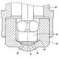
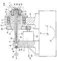
- FIG. 2 is an enlarged view of the vicinity of a nozzle body in FIG. 1.
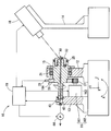
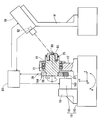
- 1 is an overall view of a drilling device according to a first embodiment of the present disclosure.
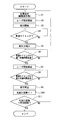
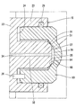
- FIG. 4 is an enlarged view of the vicinity of a rotating body of the hole punching apparatus of FIG. 3. It is an enlarged view of the V part of FIG. It is a flowchart explaining the process performed by the control unit of FIG. It is a time chart which shows the time-sequential change of the flow velocity of the measurement chamber of FIG. 3, the suction force of a pump, and the laser output of a laser irradiation device.
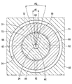
- FIG. 14 is a cross-sectional view taken along line XIV-XIV in FIG. 13.
- FIG. 18 is a cross-sectional view taken along line XVIII-XVIII in FIG. It is an enlarged view of the workpiece holding part vicinity of the drilling apparatus by 10th Embodiment of this indication. It is a general view of the drilling apparatus by a reference form.
- the drilling device according to the first embodiment of the present disclosure is used for processing the nozzle body 93 of the fuel injection valve 90 shown in FIG.
- the fuel injection valve 90 includes a housing 91, a fuel introduction pipe 92 provided at one end of the housing 91, and a nozzle body 93 provided at the other end of the housing 91. And a needle 95 provided to be able to approach and separate from a valve seat 94 formed on the inner wall of the nozzle body 93, and a drive unit 96 capable of driving the needle 95 in the axial direction.
- a suck chamber 97 is defined between the needle 95 seated on the valve seat 94 and the nozzle body 93.
- the nozzle body 93 has a plurality of nozzle holes 98 that penetrate from the outer wall surface to the inner wall surface and communicate with the sac chamber 97.
- the fuel introduced into the housing 91 from the fuel introduction pipe 92 is supplied to the sac chamber 97 when the needle 95 is separated from the valve seat 94 and is injected to the outside through the injection hole 98.
- the nozzle hole 98 is opened by the drilling apparatus 10.
- the perforating apparatus 10 includes a first support 12, a second support 13, a third support 14, a rotating body 15, a drive unit 16, and a “laser irradiation unit”.
- a laser irradiator 18 and a control unit 19 as a “control unit” are provided.
- the rotating body 15 forms a bearing portion 22 that is rotatably supported by the first support 12 via a bearing 21 and a cylindrical work holding portion 23 that protrudes from the bearing portion 22 in the axial direction.
- the work holding part 23 has a bottomed fitting hole 24 into which the nozzle body 93 can be fitted.
- the work holding unit 23 can hold the nozzle body 93.
- a sealing member 25 is provided on the tube portion of the fitting hole 24.
- the seal member 25 seals the gap between the tube portion of the fitting hole 24 and the nozzle body 93.
- a positioning pin 26 is provided at the bottom of the fitting hole 24. The positioning pin 26 engages with the nozzle body 93 to restrict relative rotation between the work holding portion 23 and the nozzle body 93.
- the drive unit 16 includes a first drive unit 161 and a second drive unit 162.
- the first drive unit 161 includes a motor 163 and a reduction gear 164.
- the motor 163 is fixed to the second support 13.
- the reduction gear 164 includes a drive gear 27 fixed to the output shaft of the motor 163 and a driven gear 28 fixed to the rotating body 15 and meshed with the drive gear 27.
- the rotation of the motor 163 is decelerated by the speed reducer 164 and transmitted to the rotating body 15.
- the first drive unit 161 can rotate the rotating body 15 around the axis AX as indicated by an arrow C in FIG.
- the second drive unit 162 is configured to move the first support 12, the second support 13, and the members (including the rotating body 15) fixed or held by the supports by arrows X, Y, and Z in FIG. 3. As shown, it can move in three directions orthogonal to each other, and can rotate about an axis parallel to the X direction as shown by an arrow A in FIG.
- the laser irradiator 18 has, for example, a laser oscillator and a lens (not shown) and is fixed to the third support 14.
- the laser irradiator 18 can open the nozzle hole 98 by irradiating the nozzle body 93 held by the work holding unit 23 with laser from the outer wall side.
- the control unit 19 is mainly composed of a microcomputer, and controls the laser irradiator 18 and the drive unit 16. Specifically, the control unit 19 controls the laser output of the laser irradiator 18 and the laser irradiation time. Further, the control unit 19 operates the drive unit 16 between laser irradiations based on the position of the rotary position sensor 29 and a position sensor (not shown) to detect the position of the laser beam and the position where the nozzle hole 98 is opened. Match the irradiated spot.
- the rotating body 15 forms a valve seat receiving portion 31 and a debris passage portion 32.
- the valve seat receiving portion 31 is formed in a cylindrical shape so as to protrude in the axial direction from the bottom portion of the fitting hole 24.
- the valve seat receiving portion 31 has a tapered valve seat receiving surface 33 that contacts the valve seat 94 of the nozzle body 93 held by the work holding portion 23.
- a clamp not shown.
- the valve seat receiving surface 33 is in close contact with the entire surface of the valve seat 94.
- the debris passage portion 32 has a debris passage 34 that is provided radially inward with respect to the valve seat receiving portion 31 and that can guide debris that is generated when the nozzle hole 98 is opened by laser light.
- the debris passage portion 32 is provided at the center of the rotating body 15.
- a debris discharge space 36 is defined between the one end portion 35 of the debris passage portion 32 and the nozzle body 93 held by the work holding portion 23.
- the debris passage 34 communicates with the debris discharge space 36.
- the one end portion 35 of the debris passage portion 32 forms a laser receiving portion 37 that receives the laser light passing through the nozzle hole 98 in the nozzle body 93 when the nozzle hole 98 penetrates.
- the other end portion 38 of the debris passage portion 32 is formed so as to protrude in the axial direction from the bearing portion 22, and is fitted in the bottomed hole 39 of the second support 13.
- the debris passage 34 is provided so as to penetrate the center of the rotating body 15 in the axial direction.
- a gap between the cylindrical portion of the bottomed hole 39 and the debris passage portion 32 is sealed with a seal member 41.
- a measurement chamber 42 is defined between the bottom surface of the bottomed hole 39 and the end surface of the debris passage portion 32.
- a flow rate sensor 43 is provided in the measurement chamber 42.
- the perforating apparatus 10 further includes a pump 44 as a “suction unit”.
- the pump 44 is connected to the measurement chamber 42 via the suction pipe 45.
- the pump 44 can suck debris discharged into the debris discharge space 36 at the moment when the nozzle hole 98 is opened through the debris passage 34, the suction pipe 45, and the measurement chamber 42.
- the flow velocity sensor 43 and the control unit 19 constitute a “penetration detection unit” that detects that the nozzle hole 98 has penetrated. Specifically, the control unit 19 starts suction by the pump 44 at the timing when the laser irradiator 18 starts irradiating laser light. Then, the control unit 19 determines that the nozzle hole 98 has penetrated when the rate of increase in the flow velocity of the measurement chamber 42 detected by the flow velocity sensor 43 becomes equal to or greater than a predetermined value.
- peernetration detection timing the timing at which it is detected that the nozzle hole 98 has penetrated is simply referred to as “penetration detection timing”.
- the control unit 19 controls the laser output of the laser irradiator 18 and the suction force of the pump 44 based on the penetration detection timing. Specifically, the control unit 19 stops the output of the laser beam by the laser irradiator 18 when a predetermined first waiting time has elapsed from the penetration detection timing. The first waiting time is set to a necessary and sufficient time from the moment when the nozzle hole 98 penetrates until the edge on the inner wall side of the nozzle hole 98 is completely removed. Further, the control unit 19 increases the suction force of the pump 44 at the penetration detection timing. Further, the control unit 19 stops the suction by the pump 44 when a predetermined second waiting time has elapsed from the penetration detection timing. The second waiting time is set to a necessary and sufficient time from the moment of penetration until the debris discharged into the debris discharge space 36 is completely removed.
- the control unit 19 realizes each function described above by executing the processing shown in FIG.
- the processing of the series of steps shown below is executed after conditions such as the nozzle body 93 is set on the work holding unit 23 are satisfied.
- step S1 the drive unit 16 is operated, and the position where the nozzle hole 98 is opened is matched with the irradiation position of the laser beam. After step S1, the process proceeds to step S2.
- step S2 laser light irradiation by the laser irradiator 18 is started. After step S2, the process proceeds to step S3.
- step S3 suction by the pump 44 is started. After step S3, the process proceeds to step S4.
- step S4 it is determined whether or not the injection hole 98 has penetrated. In the present embodiment, it is determined that the nozzle hole 98 has penetrated when the rate of increase in the flow velocity of the measurement chamber 42 is equal to or greater than a predetermined value. While the determination in step S4 is negative (S4: No), the process repeats step S4. On the other hand, when the determination in step S4 is affirmative (S4: Yes), the process proceeds to step S5.
- step S5 the suction force of the pump 44 is increased. After step S5, the process proceeds to step S6.
- step S6 it is determined whether or not the first waiting time has elapsed from the penetration detection timing. While the determination in step S6 is negative (S6: No), the process repeats step S6. On the other hand, when determination of step S6 is affirmed (S6: Yes), a process transfers to step S7.
- step S7 the laser irradiation by the laser irradiator 18 is stopped. After step S7, the process proceeds to step S8.
- step S8 it is determined whether or not the second waiting time has elapsed from the penetration detection timing. While the determination in step S8 is negative (S8: No), the process repeats step S8. On the other hand, when determination of step S8 is affirmed (S8: Yes), a process transfers to step S9.
- step S9 the suction by the pump 44 is stopped. After step S9, the process proceeds to step S10.
- step S10 the counter of the number of times of drilling (the number of times the nozzle hole 98 is opened) is counted up once. After step S10, the process proceeds to step S11.
- step S11 it is determined whether or not the number of holes has reached a predetermined number. If the determination in step S11 is negative (S11: No), the process returns to step S1. On the other hand, if the determination in step S11 is affirmative (S11: Yes), the process exits the routine of FIG.
- FIG. 7 is a time chart showing time-series changes in the flow rate of the measurement chamber 42, the suction force of the pump 44, and the laser output of the laser irradiator 18.
- laser light irradiation by the laser irradiator 18 is started and suction by the pump 44 is started.
- the nozzle hole 98 penetrates, so that the flow velocity rises after a momentary drop.
- the control unit 19 determines that the nozzle hole 98 has penetrated, and the suction force is increased.
- the debris passage portion 32 has a debris passage 34 that is provided radially inward with respect to the valve seat receiving portion 31 and guides debris that is generated when the injection hole 98 is opened.
- the pump 44 sucks debris through the debris passage 34.
- the control unit 19 controls the laser output of the laser irradiator 18 and the suction force of the pump 44.
- valve seat receiving portion 31 that contacts the valve seat 94
- the valve seat 94 is protected from debris by the valve seat receiving portion 31. That is, the debris discharged into the nozzle body 93 at the moment when the nozzle hole 98 is opened is sucked through the debris passage 34 and the like without touching the valve seat 94. Therefore, according to 1st Embodiment, it can suppress that a debris adheres to the valve seat 94.
- FIG. 1st Embodiment it can suppress that a debris adheres to the valve seat 94.
- the flow rate sensor 43 and the control unit 19 are included as a “penetration detection unit” that detects that the injection hole 98 has penetrated.
- the control unit 19 controls the laser output of the laser irradiator 18 and the suction force of the pump 44 based on the penetration detection timing.
- the laser beam is continuously irradiated unnecessarily after the nozzle hole 98 penetrates, the suction force is increased unnecessarily before the nozzle hole 98 penetrates, and the nozzle hole 98 penetrates. It is possible to avoid unnecessary suction. Therefore, power consumption can be reduced.
- control unit 19 stops the output of the laser beam by the laser irradiator 18 when the first standby time T1 has elapsed from the penetration detection timing.
- the laser irradiation can be stopped after the edge of the nozzle hole 98 on the side of the sack chamber 97 is cleanly processed.
- control unit 19 starts the suction by the pump 44 after the laser irradiation by the laser irradiator 18 is started until the nozzle hole 98 penetrates. Further, the control unit 19 increases the suction force of the pump 44 at the penetration detection timing. Further, the control unit 19 stops the suction by the pump 44 when the second waiting time T2 has elapsed from the penetration detection timing.
- the debris passage portion 32 forms a laser receiving portion 37 that receives the laser light passing through the nozzle hole 98 penetrating in the nozzle body 93.
- the valve seat receiving portion 31 has a convex curved valve seat receiving surface 51.
- the valve seat receiving surface 51 is in contact with a radially inner portion of the valve seat 94.
- the same effect as that of the first embodiment can be obtained.
- a seal as a “seal portion” positioned between the valve seat 94 and the valve seat receiving portion 31 of the nozzle body 93 held by the work holding portion 23.
- a member 53 is provided.
- the seal member 53 is an O-ring, for example. Further, the seal member 53 contacts a radially inner portion of the valve seat 94.
- the material of the valve seat receiving portion 55 is elastic such as rubber.
- the material of the laser receiving portion 37 is, for example, zirconia, which is difficult to melt by laser light.
- the material of at least the portion of the valve seat receiving portion 55 that contacts the valve seat 94 is optimized to improve functionality. be able to.
- the valve seat receiving portion 55 has improved adhesion to the valve seat 94, and the laser receiving portion 37 is prevented from being damaged by the laser beam.
- a pressure sensor 57 is provided in the measurement chamber 42 as shown in FIG.
- the pressure sensor 57 is provided in place of the flow velocity sensor 43 in the first embodiment.
- the pressure sensor 57 and the control unit 19 constitute a “penetration detection unit”.
- the control unit 19 determines that the nozzle hole 98 has penetrated when the rate of increase in the pressure of the measurement chamber 42 detected by the pressure sensor 57 becomes a predetermined value or more.
- a pump rotation speed sensor 59 that detects the rotation speed of the pump 44 is provided.
- the pump speed sensor 59 is provided in place of the flow rate sensor 43 in the first embodiment.
- the pump rotation speed sensor 59 and the control unit 19 constitute a “penetration detection unit”.
- the control unit 19 determines that the nozzle hole 98 has penetrated when the rate of increase in the rotational speed of the pump 44 detected by the pump rotational speed sensor 59 becomes equal to or greater than a predetermined value.
- the valve seat receiving portion 61 has an external communication passage 62 that communicates with the debris discharge space 36 and communicates with the external space.
- the external communication path 62 is connected to the external space through the gap 63 between the bottom of the fitting hole 24 and the nozzle body 93 and the through hole 64 of the work holding part 23. Therefore, since the suction by the pump 44 is started before the nozzle hole 98 penetrates, the air flow from the external communication path 62 to the debris discharge space 36 through the debris discharge space 36 as shown by the dashed arrow in FIG. It can be generated before the nozzle hole 98 penetrates. Therefore, the debris can be efficiently removed by being carried on the airflow already generated when the nozzle hole 98 penetrates.
- the external communication passage 62 is a groove formed at a location facing the valve seat 94 of the nozzle body 93 held by the work holding portion 23. Therefore, it is possible to generate an airflow that flows from the outside to the inside of the debris discharge space 36 in the radial direction. Therefore, debris can be removed efficiently.
- the circumferential angle range ⁇ ⁇ b> 1 occupied by the external communication path 62 overlaps with the circumferential angle range ⁇ ⁇ b> 2 occupied by the laser beam irradiation spot 65 by the laser irradiator 18. ing. Therefore, it is possible to generate an air flow in the vicinity of the injection hole 98 from the external communication passage 62 through the debris discharge space 36 toward the debris passage 34. Therefore, debris can be removed efficiently.
- the external communication path 67 is a hole.
- the air flow from the external communication passage 67 to the debris passage 34 through the debris discharge space 36 as indicated by the dashed arrow in FIG. Can be generated before the nozzle hole 98 penetrates.
- a cover portion 71 is provided to close the nozzle hole 98 that is already open at a place other than the laser light irradiation portion.
- the cover portion 71 is provided integrally with the debris passage portion 72 and closes the nozzle hole 98 from the inner wall side of the nozzle body 93.
- the cover portion 71 is formed so as to protrude in the axial direction from the debris passage portion 72, and has a notch 73 in a part in the circumferential direction corresponding to the laser light irradiation location.
- the valve seat receiving portion 31 can rotate relative to the debris passage portion 72.
- the debris passage 72 is fixed to the second support 13.
- the rotating body 75 includes the bearing portion 22, the work holding portion 23, and the valve seat receiving portion 31.
- the driving unit 16 can drive the rotating body 75 around the axis AX together with the nozzle body 93 in a state where the valve seat receiving unit 31 is in contact with the valve seat 94. With this configuration, it is possible to change the position at which the nozzle hole 98 of the nozzle body 93 is opened without changing the relative positional relationship between the laser light irradiation portion and the cover portion 71.
- a cover portion 77 is provided to close the nozzle hole 98 that is already open at a place other than the laser light irradiation location.
- the cover 77 closes the nozzle hole 98 from the outer wall side of the nozzle body 93.
- the cover portion 77 is provided so as to be movable in a direction parallel to the axis AX by, for example, the second support 13 (see FIG. 3). By being configured in this way, it is possible to suppress a reduction in suction force due to air entering the debris discharge space 36 from the already opened nozzle hole 98.
- FIG. 1 A reference form is shown in FIG.
- the rotating body 81 includes the bearing portion 22, the work holding portion 23, and the valve seat receiving portion 31. There is no debris passage and no pump.
- a distance sensor 82 is provided instead of the flow rate sensor 43 in the first embodiment.
- the distance sensor 82 detects the distance between the laser irradiator 18 and the laser irradiation location based on the laser beam bounced from the irradiation location.
- the distance sensor 82 and the control unit 83 constitute a “penetration detection unit” that detects that the nozzle hole 98 has penetrated. Specifically, the control unit 19 determines that the nozzle hole 98 has penetrated when the distance detected by the distance sensor 82 is equal to or greater than a predetermined value.
- the control unit 83 has functions other than the functions related to suction among the functions of the control unit 19 in the first embodiment. That is, the control unit 83 controls the laser output of the laser irradiator 18 based on the penetration detection timing. Specifically, the control unit 83 stops the output of the laser beam by the laser irradiator 18 when a predetermined first waiting time has elapsed from the penetration detection timing.
- the penetration detection unit may determine that the nozzle hole has penetrated based on an applied voltage or a supply current to the pump. Further, the penetration detection unit may determine that the nozzle hole has penetrated based on a detection value of a light-related value by an optical sensor provided at a location other than the laser irradiation site in the debris discharge space. In short, a parameter that changes when the nozzle hole penetrates may be used.
- the penetration detection unit may not be provided, and laser light irradiation may be performed for a predetermined time. At that time, the laser output may be constant from start to finish or may be changed according to time.
- the penetration detection unit may not be provided, and suction may be performed for a predetermined time. At that time, the suction force may be constant from start to finish or may be changed according to time.
- the laser beam irradiation and the suction may not be started simultaneously.
- the material of the laser receiving portion is not limited to zirconia, and may be, for example, ceramic. In short, it may be made of a material that is not easily melted by laser light as compared with the metal constituting the nozzle body.
- the drive unit has five drive shafts.
- the drive unit may have four or less drive shafts or six or more drive shafts.
- a drive unit capable of moving the laser irradiation unit relative to the valve seat receiving unit may be provided.
Landscapes
- Engineering & Computer Science (AREA)
- Physics & Mathematics (AREA)
- Optics & Photonics (AREA)
- Mechanical Engineering (AREA)
- Plasma & Fusion (AREA)
- Manufacturing & Machinery (AREA)
- Chemical & Material Sciences (AREA)
- Combustion & Propulsion (AREA)
- General Engineering & Computer Science (AREA)
- Laser Beam Processing (AREA)
Abstract
孔開け加工装置(10)は、ワーク保持部(23)、弁座受け部(31)およびデブリ通路部(32)を有する回転体(15)と、レーザ照射器(18)と、ポンプ(44)と、制御ユニット(19)とを備える。ワーク保持部(23)はノズルボディ(93)を保持可能である。弁座受け部(31)は、ワーク保持部(23)に保持されたノズルボディ(93)の弁座(94)に接触する。レーザ照射器(18)は、ワーク保持部(23)に保持されたノズルボディ(93)に外壁側からレーザ光を照射して噴孔(98)を開ける。デブリ通路部(32)は、弁座受け部(31)に対して径方向内側に設けられ、噴孔(98)が開けられるとき生じるデブリを導くデブリ通路(34)を有する。ポンプ(44)は、デブリ通路(34)を通じてデブリを吸引する。制御ユニット(19)は、レーザ照射器のレーザ出力およびポンプ(44)の吸引力を制御する。
Description
本願は、2015年1月22日に出願された日本国特許出願第2015-10282号に基づくものであり、この開示をもってその内容を本明細書中に開示したものとする。
本開示は、ノズルボディの孔開け加工装置に関する。
レーザ光によりノズルボディに噴孔を開ける孔開け加工装置が知られている。例えば引用文献1に開示された孔開け加工装置は、ノズルボディ内に挿入される挿入部材を備えている。挿入部材の先端部には、噴孔を通過したレーザ光を受ける芯体が設けられている。芯体は、噴孔が開けられるとき生じるデブリを導く連通孔を有する。デブリとは、レーザ加工時に光エネルギにより蒸発した金属のことである。デブリは、ポンプにより連通孔を通じて吸引される。
ところで、特許文献1では、挿入部材の外壁とノズルボディの内壁との間に区画形成される空間をデブリ吸引通路として利用している。このデブリ吸引通路には、芯体の外壁とノズルボディの弁座との間の空間(弁座隣接空間)が含まれている。芯体の連通孔の出口は、弁座隣接空間につながっている。
さらに、特許文献1では、芯体の外壁とノズルボディのサック室内壁との間に隙間がある状態でレーザ加工が行われる。噴孔からデブリが排出される空間は、上記隙間を介して弁座隣接空間につながっている。そのため、上記隙間が連通孔よりも小さい場合であっても、少なからず噴孔から上記隙間を通じて弁座隣接空間に向かう流れは生じる。
したがって、特許文献1に開示された孔開け加工装置では、デブリがノズルボディの弁座に付着するおそれがあった。
本開示は、上述の点に鑑みてなされたものであり、その目的は、デブリがノズルボディの弁座に付着することを抑制可能な孔開け加工装置を提供することである。
本開示による孔開け加工装置は、ワーク保持部、弁座受け部、レーザ照射部、デブリ通路部、吸引部および制御部を備える。ノズルボディに噴孔を開ける際、ワーク保持部はノズルボディを保持する。弁座受け部は、ワーク保持部に保持されたノズルボディの弁座に接触する。レーザ照射部は、ワーク保持部に保持されたノズルボディに外壁側からレーザ光を照射して噴孔を開ける。デブリ通路部は、弁座受け部に対して径方向内側に設けられ、噴孔が開けられるとき生じるデブリを導くデブリ通路を有する。吸引部は、デブリ通路を通じてデブリを吸引する。制御部は、レーザ照射部のレーザ出力および吸引部の吸引力を制御する。
このように弁座に接触する弁座受け部を設けることで、弁座は、弁座受け部によってデブリから守られる。つまり、噴孔が開いた瞬間にノズルボディ内に排出されるデブリは、弁座に触れることなくデブリ通路を通じて吸引される。したがって、本開示によれば、デブリが弁座に付着することを抑制可能である。
以下、本開示の複数の実施形態を図面に基づき説明する。実施形態同士で実質的に同一の構成には同一の符号を付して説明を省略する。
[第1実施形態]
本開示の第1実施形態による孔開け加工装置は、図1に示す燃料噴射弁90のノズルボディ93の加工に用いる。
本開示の第1実施形態による孔開け加工装置は、図1に示す燃料噴射弁90のノズルボディ93の加工に用いる。
図1、図2に示すように、燃料噴射弁90は、ハウジング91と、ハウジング91の一端部に設けられている燃料導入パイプ92と、ハウジング91の他端部に設けられているノズルボディ93と、ノズルボディ93の内壁に形成された弁座94に接近および離間可能に設けられているニードル95と、ニードル95を軸方向へ駆動可能な駆動部96と、を備えている。
弁座94に着座したニードル95とノズルボディ93との間には、サック室97が区画形成される。ノズルボディ93は、外壁面から内壁面まで貫通し且つサック室97に連通する複数の噴孔98を有する。燃料導入パイプ92からハウジング91に導入された燃料は、ニードル95が弁座94から離座したときサック室97に供給されて噴孔98から外部に噴射される。噴孔98は、孔開け加工装置10により開けられる。
(基本構成)
先ず、孔開け加工装置の基本構成について図3、図4を参照して説明する。
先ず、孔開け加工装置の基本構成について図3、図4を参照して説明する。
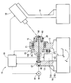
図3、図4に示すように、孔開け加工装置10は、第1支持体12、第2支持体13、第3支持体14、回転体15、駆動部16、「レーザ照射部」としてのレーザ照射器18、および、「制御部」としての制御ユニット19などを備えている。
回転体15は、軸受21を介して第1支持体12により回転可能に支持されている軸受部22と、軸受部22から軸方向へ突き出す筒状のワーク保持部23とを形成している。ワーク保持部23は、ノズルボディ93が嵌合可能な有底の嵌合穴24を有している。ワーク保持部23はノズルボディ93を保持可能である。
嵌合穴24の筒部にはシール部材25が設けられている。シール部材25は、嵌合穴24の筒部とノズルボディ93との隙間を封止する。また、嵌合穴24の底部には位置決めピン26が設けられている。位置決めピン26は、ノズルボディ93と係合して、ワーク保持部23とノズルボディ93との相対回転を規制する。
駆動部16は、第1駆動部161および第2駆動部162を含む。
第1駆動部161は、モータ163および減速機164から構成されている。モータ163は第2支持体13に固定されている。減速機164は、モータ163の出力軸に固定されているドライブギヤ27と、回転体15に固定されるとともにドライブギヤ27に噛み合うドリブンギヤ28とから構成されている。モータ163の回転は、減速機164により減速されて回転体15に伝達される。第1駆動部161は、図3中に矢印Cで示すように回転体15を軸心AXまわりに回転可能である。
第2駆動部162は、第1支持体12と第2支持体13と各支持体に固定または保持された部材(回転体15を含む)とを、図3中に矢印X、Y、Zで示すように互いに直交する3方向へ移動可能であるとともに、図3中に矢印Aで示すようにX方向と平行な軸まわりに回転可能である。
レーザ照射器18は、例えば図示しないレーザ発振器およびレンズ等を有しており、第3支持体14に固定されている。レーザ照射器18は、ワーク保持部23に保持されたノズルボディ93に外壁側からレーザを照射して噴孔98を開けることが可能である。
制御ユニット19は、マイクロコンピュータを主体として構成されており、レーザ照射器18および駆動部16を制御する。具体的には、制御ユニット19は、レーザ照射器18のレーザ出力およびレーザ照射時間などを制御する。また、制御ユニット19は、回転位置センサ29および図示しない位置センサが検出する回転体15の位置に基づき、レーザ照射の合間に駆動部16を作動させて、噴孔98を開ける位置とレーザ光の照射箇所とを一致させる。
(特徴構成)
次に、孔開け加工装置10の特徴構成について図3~図6を参照して説明する。
次に、孔開け加工装置10の特徴構成について図3~図6を参照して説明する。
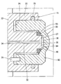
図4、図5に示すように、回転体15は、弁座受け部31およびデブリ通路部32を形成している。
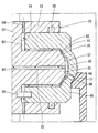
図5に示すように、弁座受け部31は、嵌合穴24の底部から軸方向へ突き出すように筒状に形成されている。弁座受け部31は、ワーク保持部23に保持されたノズルボディ93の弁座94に接触するテーパ面状の弁座受け面33を有する。本実施形態では、ノズルボディ93は、ワーク保持部23に保持されるとき、図示しないクランプによって嵌合穴24の底部側へ押圧される。これにより、弁座受け面33は弁座94の全面に密着する。
デブリ通路部32は、弁座受け部31に対して径方向内側に設けられ、レーザ光により噴孔98が開けられるとき生じるデブリを導くことが可能なデブリ通路34を有する。本実施形態では、デブリ通路部32は、回転体15の中心部に設けられている。デブリ通路部32の一端部35は、ワーク保持部23に保持されたノズルボディ93との間にデブリ排出空間36を区画形成する。デブリ通路34はデブリ排出空間36に連通する。また、デブリ通路部32の一端部35は、噴孔98が貫通したとき噴孔98を通過するレーザ光をノズルボディ93内で受けるレーザ受け部37を形成している。
図4に示すように、デブリ通路部32の他端部38は、軸受部22から軸方向へ突き出すように形成されており、第2支持体13の有底穴39に嵌合している。デブリ通路34は、回転体15の中心を軸方向へ貫通するように設けられている。有底穴39の筒部とデブリ通路部32との隙間は、シール部材41により封止されている。有底穴39の底面とデブリ通路部32の端面との間には測定室42が区画形成されている。測定室42には流速センサ43が設けられている。
図3に示すように、孔開け加工装置10は、「吸引部」としてのポンプ44をさらに備えている。ポンプ44は、吸引管45を介して測定室42に接続されている。ポンプ44は、噴孔98が開いた瞬間にデブリ排出空間36に排出されるデブリを、デブリ通路34と吸引管45内部と測定室42とを通じて吸引可能である。
流速センサ43および制御ユニット19は、噴孔98が貫通したことを検知する「貫通検知部」を構成している。具体的には、制御ユニット19は、レーザ照射器18がレーザ光を照射し始めるタイミングでポンプ44による吸引を開始する。そして、制御ユニット19は、流速センサ43が検出する測定室42の流速の上昇率が所定値以上となったとき、噴孔98が貫通したと判定する。以下、噴孔98が貫通したことを検知したタイミングを単に「貫通検知タイミング」と記載する。
制御ユニット19は、貫通検知タイミングに基づきレーザ照射器18のレーザ出力およびポンプ44の吸引力を制御する。具体的には、制御ユニット19は、貫通検知タイミングから所定の第1待機時間経過したときレーザ照射器18によるレーザ光の出力を停止する。第1待機時間は、噴孔98が貫通した瞬間から、噴孔98のうち内壁側の縁部が完全に除去されるまでにかかる必要十分な時間に設定される。また、制御ユニット19は、貫通検知タイミングでポンプ44の吸引力を増大させる。また、制御ユニット19は、貫通検知タイミングから所定の第2待機時間経過したときポンプ44による吸引を停止する。第2待機時間は、貫通した瞬間から、デブリ排出空間36に排出されるデブリが完全に除去されるまでにかかる必要十分な時間に設定される。
制御ユニット19は、図6に示す処理を実行することによって上述の各機能を実現させる。以下に示す一連のステップの処理は、例えばノズルボディ93がワーク保持部23にセットされる等の条件が整ってから実行される。
図6の処理の実行が開始されると、先ずステップS1では、駆動部16が作動させられて、噴孔98を開ける位置とレーザ光の照射箇所とが一致させられる。ステップS1のあと、処理はステップS2に移行する。
ステップS2では、レーザ照射器18によるレーザ光の照射が開始される。ステップS2のあと、処理はステップS3に移行する。
ステップS3では、ポンプ44による吸引が開始される。ステップS3のあと、処理はステップS4に移行する。
ステップS4では、噴孔98が貫通したか否かが判定される。本実施形態では、測定室42の流速の上昇率が所定値以上となったとき噴孔98が貫通したと判定される。ステップS4の判定が否定される間(S4:No)、処理はステップS4を繰り返す。一方、ステップS4の判定が肯定された場合(S4:Yes)、処理はステップS5に移行する。
ステップS5では、ポンプ44の吸引力が増大される。ステップS5のあと、処理はステップS6に移行する。
ステップS6では、貫通検知タイミングから第1待機時間が経過したか否かが判定される。ステップS6の判定が否定される間(S6:No)、処理はステップS6を繰り返す。一方、ステップS6の判定が肯定された場合(S6:Yes)、処理はステップS7に移行する。
ステップS7では、レーザ照射器18によるレーザ光の照射が停止される。ステップS7のあと、処理はステップS8に移行する。
ステップS8では、貫通検知タイミングから第2待機時間が経過したか否かが判定される。ステップS8の判定が否定される間(S8:No)、処理はステップS8を繰り返す。一方、ステップS8の判定が肯定された場合(S8:Yes)、処理はステップS9に移行する。
ステップS9では、ポンプ44による吸引が停止される。ステップS9のあと、処理はステップS10に移行する。
ステップS10では、孔開け回数(噴孔98を開けた回数)のカウンタが1回カウントアップされる。ステップS10のあと、処理はステップS11に移行する。
ステップS11では、孔開け回数が所定回数に達したか否かが判定される。ステップS11の判定が否定される場合(S11:No)、処理はステップS1に戻る。一方、ステップS11の判定が肯定された場合(S11:Yes)、処理は図6のルーチンを抜ける。
図7は、測定室42の流速、ポンプ44の吸引力およびレーザ照射器18のレーザ出力の時系列変化を示すタイムチャートである。時刻t0では、レーザ照射器18によるレーザ光の照射が開始されるとともに、ポンプ44による吸引が開始される。時刻t1では、噴孔98が貫通することによって、流速が一瞬低下したあと上昇する。時刻t2では、流速の上昇率が所定値以上となることに伴って、制御ユニット19により噴孔98が貫通したと判定されて吸引力が増大される。貫通検知タイミングである時刻t2から第1待機時間T1経過した時刻t3では、レーザ照射器18によるレーザ光の照射が停止される。時刻t2から第2待機時間T2経過した時刻t4では、ポンプ44の吸引力が低下させられる。
(効果)
以上説明したように、第1実施形態では、孔開け加工装置10は、ワーク保持部23、弁座受け部31およびデブリ通路部32を有する回転体15と、レーザ照射器18と、ポンプ44と、制御ユニット19とを備える。ワーク保持部23はノズルボディ93を保持可能である。具体的には、ノズルボディ93に噴孔98を開ける孔開け加工時に、ワーク保持部23はノズルボディ93を保持する。弁座受け部31は、ワーク保持部23に保持されたノズルボディ93の弁座94に接触する。レーザ照射器18は、ワーク保持部23に保持されたノズルボディ93に外壁側からレーザ光を照射して噴孔98を開ける。デブリ通路部32は、弁座受け部31に対して径方向内側に設けられ、噴孔98が開けられるとき生じるデブリを導くデブリ通路34を有する。ポンプ44は、デブリ通路34を通じてデブリを吸引する。制御ユニット19は、レーザ照射器18のレーザ出力およびポンプ44の吸引力を制御する。
以上説明したように、第1実施形態では、孔開け加工装置10は、ワーク保持部23、弁座受け部31およびデブリ通路部32を有する回転体15と、レーザ照射器18と、ポンプ44と、制御ユニット19とを備える。ワーク保持部23はノズルボディ93を保持可能である。具体的には、ノズルボディ93に噴孔98を開ける孔開け加工時に、ワーク保持部23はノズルボディ93を保持する。弁座受け部31は、ワーク保持部23に保持されたノズルボディ93の弁座94に接触する。レーザ照射器18は、ワーク保持部23に保持されたノズルボディ93に外壁側からレーザ光を照射して噴孔98を開ける。デブリ通路部32は、弁座受け部31に対して径方向内側に設けられ、噴孔98が開けられるとき生じるデブリを導くデブリ通路34を有する。ポンプ44は、デブリ通路34を通じてデブリを吸引する。制御ユニット19は、レーザ照射器18のレーザ出力およびポンプ44の吸引力を制御する。
このように弁座94に接触する弁座受け部31を設けることで、弁座94は、弁座受け部31によってデブリから守られる。つまり、噴孔98が開いた瞬間にノズルボディ93内に排出されるデブリは、弁座94に触れることなくデブリ通路34等を通じて吸引される。したがって、第1実施形態によれば、デブリが弁座94に付着することを抑制可能である。
また、第1実施形態では、噴孔98が貫通したことを検知する「貫通検知部」として流速センサ43および制御ユニット19を有する。制御ユニット19は、貫通検知タイミングに基づきレーザ照射器18のレーザ出力およびポンプ44の吸引力を制御する。
これにより、例えば、噴孔98が貫通したあと不必要にレーザ光を照射し続けること、噴孔98が貫通する前から不必要に吸引力を大きくすること、および、噴孔98が貫通したあと不必要に吸引し続けることを避けることができる。そのため、消費電力を低減可能である。
また、第1実施形態では、制御ユニット19は、貫通検知タイミングから第1待機時間T1経過したときレーザ照射器18によるレーザ光の出力を停止する。
このように構成することで、噴孔98のサック室97側の縁部をきれいに加工してからレーザ照射を停止することができる。
また、第1実施形態では、制御ユニット19は、レーザ照射器18によるレーザ光の照射が開始してから噴孔98が貫通するまでの間にポンプ44による吸引を開始する。また、制御ユニット19は、貫通検知タイミングでポンプ44の吸引力を増大させる。また、制御ユニット19は、貫通検知タイミングから第2待機時間T2経過したときポンプ44による吸引を停止する。
このように構成することで、噴孔98が貫通した瞬間にノズルボディ93内に流れ込むデブリを効率良く除去することができる。
また、第1実施形態では、弁座受け部31は、ワーク保持部23に保持されたノズルボディ93の弁座94に接触するテーパ面状の弁座受け面33を有する。
したがって、デブリが弁座94に付着することを抑制可能である。
また、第1実施形態では、デブリ通路部32は、貫通した噴孔98を通過するレーザ光をノズルボディ93内で受けるレーザ受け部37を形成している。
したがって、噴孔98を通過したレーザ光がノズルボディ93の内壁を傷つけることを抑制可能である。
[第2実施形態]
本開示の第2実施形態では、図8に示すように、弁座受け部31は凸曲面状の弁座受け面51を有する。弁座受け面51は、弁座94のうち径方向内側の部分に接触する。このように、弁座受け面51が凸曲面状であっても、第1実施形態と同様の効果を得ることができる。
本開示の第2実施形態では、図8に示すように、弁座受け部31は凸曲面状の弁座受け面51を有する。弁座受け面51は、弁座94のうち径方向内側の部分に接触する。このように、弁座受け面51が凸曲面状であっても、第1実施形態と同様の効果を得ることができる。
[第3実施形態]
本開示の第3実施形態では、図9に示すように、ワーク保持部23に保持されたノズルボディ93の弁座94と弁座受け部31との間に位置する「シール部」としてのシール部材53を備える。シール部材53は例えばOリングである。また、シール部材53は、弁座94のうち径方向内側の部分に接触する。このように、弁座94と弁座受け部31との間にシール部材53を設けることによって、デブリが弁座94に付着することを一層抑制可能である。
本開示の第3実施形態では、図9に示すように、ワーク保持部23に保持されたノズルボディ93の弁座94と弁座受け部31との間に位置する「シール部」としてのシール部材53を備える。シール部材53は例えばOリングである。また、シール部材53は、弁座94のうち径方向内側の部分に接触する。このように、弁座94と弁座受け部31との間にシール部材53を設けることによって、デブリが弁座94に付着することを一層抑制可能である。
[第4実施形態]
本開示の第4実施形態では、図10に示すように、弁座受け部55の材質は、例えばゴムなど、弾力性のあるものである。レーザ受け部37の材質は、例えばジルコニアなど、レーザ光により溶融しにくいものである。このように、弁座受け部55のうち少なくとも弁座94と接触する箇所の材質がレーザ受け部37の材質とは異なるように構成することで、各部の材質を最適化して機能性を向上することができる。弁座受け部55は弁座94との密着性が高まり、また、レーザ受け部37はレーザ光による損傷が抑えられる。
本開示の第4実施形態では、図10に示すように、弁座受け部55の材質は、例えばゴムなど、弾力性のあるものである。レーザ受け部37の材質は、例えばジルコニアなど、レーザ光により溶融しにくいものである。このように、弁座受け部55のうち少なくとも弁座94と接触する箇所の材質がレーザ受け部37の材質とは異なるように構成することで、各部の材質を最適化して機能性を向上することができる。弁座受け部55は弁座94との密着性が高まり、また、レーザ受け部37はレーザ光による損傷が抑えられる。
[第5実施形態]
本開示の第5実施形態では、図11に示すように、測定室42には圧力センサ57が設けられている。圧力センサ57は、第1実施形態における流速センサ43に代えて設けられる。圧力センサ57および制御ユニット19は「貫通検知部」を構成している。制御ユニット19は、圧力センサ57が検出する測定室42の圧力の上昇率が所定値以上となったとき、噴孔98が貫通したと判定する。このように、流速センサ43に代えて圧力センサ57が設けられても、第1実施形態と同様の効果を得ることができる。
本開示の第5実施形態では、図11に示すように、測定室42には圧力センサ57が設けられている。圧力センサ57は、第1実施形態における流速センサ43に代えて設けられる。圧力センサ57および制御ユニット19は「貫通検知部」を構成している。制御ユニット19は、圧力センサ57が検出する測定室42の圧力の上昇率が所定値以上となったとき、噴孔98が貫通したと判定する。このように、流速センサ43に代えて圧力センサ57が設けられても、第1実施形態と同様の効果を得ることができる。
[第6実施形態]
本開示の第6実施形態では、図12に示すように、ポンプ44の回転数を検出するポンプ回転数センサ59が設けられている。ポンプ回転数センサ59は、第1実施形態における流速センサ43に代えて設けられる。ポンプ回転数センサ59および制御ユニット19は「貫通検知部」を構成している。制御ユニット19は、ポンプ回転数センサ59が検出するポンプ44の回転数の上昇率が所定値以上となったとき、噴孔98が貫通したと判定する。このように、流速センサ43に代えてポンプ回転数センサ59が設けられても、第1実施形態と同様の効果を得ることができる。
本開示の第6実施形態では、図12に示すように、ポンプ44の回転数を検出するポンプ回転数センサ59が設けられている。ポンプ回転数センサ59は、第1実施形態における流速センサ43に代えて設けられる。ポンプ回転数センサ59および制御ユニット19は「貫通検知部」を構成している。制御ユニット19は、ポンプ回転数センサ59が検出するポンプ44の回転数の上昇率が所定値以上となったとき、噴孔98が貫通したと判定する。このように、流速センサ43に代えてポンプ回転数センサ59が設けられても、第1実施形態と同様の効果を得ることができる。
[第7実施形態]
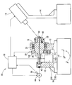
本開示の第7実施形態では、図13に示すように、弁座受け部61は、デブリ排出空間36に連通し且つ外部空間に連通している外部連通路62を有する。外部連通路62は、嵌合穴24の底部とノズルボディ93との隙間63、および、ワーク保持部23の通孔64を通じて外部空間につながっている。そのため、噴孔98が貫通する前からポンプ44による吸引が開始されることから、図13に破線の矢印で示すように外部連通路62からデブリ排出空間36を経てデブリ通路34に向かう気流を、噴孔98が貫通する前から生成することができる。したがって、噴孔98が貫通したとき既に生成されている気流に乗せてデブリを効率良く除去することができる。
本開示の第7実施形態では、図13に示すように、弁座受け部61は、デブリ排出空間36に連通し且つ外部空間に連通している外部連通路62を有する。外部連通路62は、嵌合穴24の底部とノズルボディ93との隙間63、および、ワーク保持部23の通孔64を通じて外部空間につながっている。そのため、噴孔98が貫通する前からポンプ44による吸引が開始されることから、図13に破線の矢印で示すように外部連通路62からデブリ排出空間36を経てデブリ通路34に向かう気流を、噴孔98が貫通する前から生成することができる。したがって、噴孔98が貫通したとき既に生成されている気流に乗せてデブリを効率良く除去することができる。
また、第7実施形態では、外部連通路62は、ワーク保持部23に保持されたノズルボディ93の弁座94と対向する箇所に形成されている溝である。そのため、径方向においてデブリ排出空間36の外側から内側に向かって流れる気流を生成することができる。したがって、デブリを効率良く除去することができる。
また、第7実施形態では、図14に示すように、外部連通路62が占める周方向の角度範囲θ1は、レーザ照射器18によるレーザ光の照射箇所65が占める周方向の角度範囲θ2と重なり合っている。そのため、外部連通路62からデブリ排出空間36を経てデブリ通路34に向かう気流を噴孔98付近に生成することができる。したがって、デブリを効率良く除去することができる。
[第8実施形態]
本開示の第8実施形態では、図15に示すように、外部連通路67は孔である。このように、外部連通路67が孔であっても、第7実施形態と同様に、図15に破線の矢印で示すように外部連通路67からデブリ排出空間36を経てデブリ通路34に向かう気流を、噴孔98が貫通する前から生成することができる。
本開示の第8実施形態では、図15に示すように、外部連通路67は孔である。このように、外部連通路67が孔であっても、第7実施形態と同様に、図15に破線の矢印で示すように外部連通路67からデブリ排出空間36を経てデブリ通路34に向かう気流を、噴孔98が貫通する前から生成することができる。
[第9実施形態]
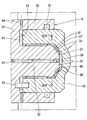
本開示の第9実施形態では、図16~図18に示すように、レーザ光の照射箇所以外で既に開いている噴孔98を塞ぐカバー部71が設けられている。カバー部71は、デブリ通路部72と一体に設けられており、ノズルボディ93の内壁側から噴孔98を塞ぐ。本実施形態では、カバー部71は、デブリ通路部72から軸方向へ突き出すように形成されており、レーザ光の照射箇所に対応する周方向の一部に切欠き73を有する。このように構成されることで、既に開いている噴孔98からデブリ排出空間36に空気が入ることに起因して吸引力が低下することを抑制可能である。
本開示の第9実施形態では、図16~図18に示すように、レーザ光の照射箇所以外で既に開いている噴孔98を塞ぐカバー部71が設けられている。カバー部71は、デブリ通路部72と一体に設けられており、ノズルボディ93の内壁側から噴孔98を塞ぐ。本実施形態では、カバー部71は、デブリ通路部72から軸方向へ突き出すように形成されており、レーザ光の照射箇所に対応する周方向の一部に切欠き73を有する。このように構成されることで、既に開いている噴孔98からデブリ排出空間36に空気が入ることに起因して吸引力が低下することを抑制可能である。
また、第9実施形態では、弁座受け部31は、デブリ通路部72に対して相対回転可能である。デブリ通路部72は第2支持体13に固定されている。回転体75は、軸受部22、ワーク保持部23および弁座受け部31から構成されている。駆動部16は、弁座受け部31が弁座94に接触したままの状態で回転体75をノズルボディ93と共に軸心AXまわりに回転駆動可能である。このように構成することで、レーザ光の照射箇所とカバー部71との相対位置関係を変えることなく、ノズルボディ93の噴孔98を開ける位置を変更することができる。
[第10実施形態]
本開示の第10実施形態では、図19に示すように、レーザ光の照射箇所以外で既に開いている噴孔98を塞ぐカバー部77が設けられている。カバー部77は、ノズルボディ93の外壁側から噴孔98を塞ぐ。カバー部77は、例えば第2支持体13(図3参照)により軸心AXに平行方向へ移動可能に設けられる。このように構成されることで、既に開いている噴孔98からデブリ排出空間36に空気が入ることに起因して吸引力が低下することを抑制可能である。
本開示の第10実施形態では、図19に示すように、レーザ光の照射箇所以外で既に開いている噴孔98を塞ぐカバー部77が設けられている。カバー部77は、ノズルボディ93の外壁側から噴孔98を塞ぐ。カバー部77は、例えば第2支持体13(図3参照)により軸心AXに平行方向へ移動可能に設けられる。このように構成されることで、既に開いている噴孔98からデブリ排出空間36に空気が入ることに起因して吸引力が低下することを抑制可能である。
[参考形態]
参考形態を図20に示す。参考形態では、回転体81は、軸受部22、ワーク保持部23および弁座受け部31から構成されている。デブリ通路およびポンプは設けられていない。
参考形態を図20に示す。参考形態では、回転体81は、軸受部22、ワーク保持部23および弁座受け部31から構成されている。デブリ通路およびポンプは設けられていない。
第1実施形態における流速センサ43に変えて、距離センサ82が設けられている。距離センサ82は、照射箇所から跳ね返ってくるレーザ光に基づき、レーザ照射器18とレーザ照射箇所との距離を検出する。
距離センサ82および制御ユニット83は、噴孔98が貫通したことを検知する「貫通検知部」を構成している。具体的には、制御ユニット19は、距離センサ82が検出する距離が所定値以上となったとき、噴孔98が貫通したと判定する。
制御ユニット83は、第1実施形態における制御ユニット19が有する機能のうち、吸引に関する機能以外を有する。つまり、制御ユニット83は、貫通検知タイミングに基づきレーザ照射器18のレーザ出力を制御する。具体的には、制御ユニット83は、貫通検知タイミングから所定の第1待機時間経過したときレーザ照射器18によるレーザ光の出力を停止する。
[他の実施形態]
本開示の他の実施形態では、貫通検知部は、ポンプへの印加電圧または供給電流などに基づき噴孔が貫通したことを判定してもよい。また、貫通検知部は、デブリ排出空間のうちレーザ照射部位以外の箇所に設けられた光センサによる光関連値の検出値に基づき噴孔が貫通したことを判定してもよい。要するに、噴孔が貫通したときに変化するパラメータを用いればよい。
本開示の他の実施形態では、貫通検知部は、ポンプへの印加電圧または供給電流などに基づき噴孔が貫通したことを判定してもよい。また、貫通検知部は、デブリ排出空間のうちレーザ照射部位以外の箇所に設けられた光センサによる光関連値の検出値に基づき噴孔が貫通したことを判定してもよい。要するに、噴孔が貫通したときに変化するパラメータを用いればよい。
本開示の他の実施形態では、貫通検知部が設けられず、予め決められた時間だけレーザ光の照射が行われてもよい。その際、レーザ出力は、終始一定であってもよいし、時間に応じて変化させてもよい。
本開示の他の実施形態では、貫通検知部が設けられず、予め決められた時間だけ吸引が行われてもよい。その際、吸引力は、終始一定であってもよいし、時間に応じて変化させてもよい。
本開示の他の実施形態では、弁座受け部は、金属またはゴムに限らず、例えば樹脂等であってもよい。
本開示の他の実施形態では、レーザ光の照射と吸引とが同時に開始されなくてもよい。
本開示の他の実施形態では、レーザ受け部の材質は、ジルコニアに限らず、例えばセラミック等であってもよい。要するに、ノズルボディを構成する金属と比べてレーザ光により溶融しにくい材料から構成されていればよい。
第1~第10実施形態では、駆動部は、駆動軸を5軸持つものであった。これに対して、本開示の他の実施形態では、駆動部は、駆動軸を4軸以下または6軸以上もつものであってもよい。
本開示の他の実施形態では、レーザ照射部を弁座受け部に対して相対移動させることが可能な駆動部を備えていてもよい。
本開示は、上述した実施形態に限定されるものではなく、本開示の趣旨を逸脱しない範囲で種々の形態で実施可能である。
Claims (17)
- 内壁に弁座(94)を有するノズルボディ(93)に噴孔(98)を開ける孔開け加工装置であって、
前記ノズルボディ(93)に前記噴孔(98)を開ける際に前記ノズルボディ(93)を保持するワーク保持部(23)と、
前記ワーク保持部(23)に保持された前記ノズルボディ(93)の前記弁座(94)に接触する弁座受け部(31、55、61)と、
前記ワーク保持部(23)に保持された前記ノズルボディ(93)に外壁側からレーザ光を照射して前記噴孔(98)を開けるレーザ照射部(18)と、
前記弁座受け部(31、55、61)に対して径方向内側に設けられ、前記噴孔(98)が開けられるとき生じるデブリを導くデブリ通路(34)を有するデブリ通路部(32、72)と、
前記デブリ通路(34)を通じて前記デブリを吸引する吸引部(44)と、
前記レーザ照射部(18)のレーザ出力および前記吸引部(44)の吸引力を制御する制御部(19)と、
を備える孔開け加工装置。 - 前記制御部(19)は、前記噴孔(98)が前記ノズルボディ(93)において貫通する前から前記吸引部(44)による吸引を開始する請求項1に記載の孔開け加工装置。
- 前記デブリ通路部(32、72)は、前記ワーク保持部(23)に保持された前記ノズルボディ(93)との間にデブリ排出空間(36)を区画形成し、
前記デブリ通路(34)は、前記デブリ排出空間(36)に連通し、
前記弁座受け部(61)は、前記デブリ排出空間(36)に連通し且つ外部空間に連通している外部連通路(62、67)を有する請求項1または2に記載の孔開け加工装置。 - 前記外部連通路(62)は、前記ワーク保持部(23)に保持された前記ノズルボディ(93)の前記弁座(94)と対向する前記弁座受け部(61)の対向箇所に形成されている溝である請求項3に記載の孔開け加工装置。
- 前記外部連通路(62、67)が占める周方向の角度範囲は、前記ノズルボディ(93)において前記レーザ照射部(18)によるレーザ光の照射箇所(65)が占める周方向の角度範囲と重なり合っている請求項3または4に記載の孔開け加工装置。
- 前記ノズルボディ(93)において前記噴孔(98)が貫通したことを検知する貫通検知部(19、43、57、59)をさらに備え、
前記制御部(19)は、前記ノズルボディ(93)において前記噴孔(98)が貫通したことを前記貫通検知部(19、43、57、59)が検知した際に前記レーザ照射部(18)のレーザ出力および前記吸引部(44)の吸引力の少なくとも一方を制御する請求項1~5のいずれか一項に記載の孔開け加工装置。 - 前記制御部(19)は、前記噴孔(98)が貫通したことを前記貫通検知部(19、43、57、59)が検知してから所定の第1待機時間経過したとき前記レーザ照射部(18)のレーザ出力を低下させるか又は前記レーザ照射部(18)によるレーザ光の出力を停止する請求項6に記載の孔開け加工装置。
- 前記制御部(19)は、
前記噴孔(98)が貫通したことを前記貫通検知部(19、43、57、59)が検知する前から前記吸引部(44)による吸引を開始し、
前記噴孔(98)が貫通したことを前記貫通検知部(19、43、57、59)が検知したとき前記吸引部(44)の吸引力を増大させ、
前記噴孔(98)が貫通したことを前記貫通検知部(19、43、57、59)が検知してから所定の第2待機時間経過したとき前記吸引部(44)の吸引力を低下させるか又は前記吸引部(44)による吸引を停止する請求項6または7に記載の孔開け加工装置。 - 前記弁座受け部(31、55、61)は、前記ワーク保持部(23)に保持された前記ノズルボディ(93)の前記弁座(94)に接触するテーパ面状の弁座受け面(33)を有する請求項1~8のいずれか一項に記載の孔開け加工装置。
- 前記弁座受け部(31)は、前記ワーク保持部(23)に保持された前記ノズルボディ(93)の前記弁座(94)に接触する凸曲面状の弁座受け面(51)を有する請求項1~8のいずれか一項に記載の孔開け加工装置。
- 前記ワーク保持部(23)に保持された前記ノズルボディ(93)の前記弁座(94)と前記弁座受け部(31)との間に位置するシール部(53)をさらに備える請求項1~10のいずれか一項に記載の孔開け加工装置。
- 前記デブリ通路部(32)は、前記噴孔(98)を通過したレーザ光を前記ノズルボディ(93)内で受けるレーザ受け部(37)を有し、
前記弁座受け部(55)のうち、少なくとも前記弁座(94)と接触する箇所の材質は、前記レーザ受け部(37)の材質とは異なる請求項1~11のいずれか一項に記載の孔開け加工装置。 - 前記ノズルボディ(93)における前記レーザ照射部(18)によるレーザ光の照射箇所(65)以外で既に開いている前記噴孔(98)を塞ぐカバー部(71、77)をさらに備える請求項1~12のいずれか一項に記載の孔開け加工装置。
- 前記カバー部(71)は、前記デブリ通路部(72)と一体に設けられており、前記ノズルボディ(93)の内壁側から前記噴孔(98)を塞ぐ請求項13に記載の孔開け加工装置。
- 前記カバー部(77)は、前記ノズルボディ(93)の外壁側から前記噴孔(98)を塞ぐ請求項13に記載の孔開け加工装置。
- 前記弁座受け部(31、55、61)は前記レーザ照射部(18)に対して相対回転可能であり、
前記弁座受け部(31、55、61)が前記弁座(94)に接触したままの状態で当該弁座受け部(31、55、61)を前記ノズルボディ(93)と共に軸心まわりに回転駆動可能な駆動部(16)をさらに備える請求項1~15のいずれか一項に記載の孔開け加工装置。 - 前記弁座受け部(61)は、前記デブリ通路部(72)に対して相対回転可能である請求項16に記載の孔開け加工装置。
Priority Applications (3)
| Application Number | Priority Date | Filing Date | Title |
|---|---|---|---|
| DE112016000458.3T DE112016000458T5 (de) | 2015-01-22 | 2016-01-15 | Bohrvorrichtung |
| US15/520,229 US20170304904A1 (en) | 2015-01-22 | 2016-01-15 | Boring device |
| CN201680004210.5A CN107107272A (zh) | 2015-01-22 | 2016-01-15 | 开孔加工装置 |
Applications Claiming Priority (2)
| Application Number | Priority Date | Filing Date | Title |
|---|---|---|---|
| JP2015-010282 | 2015-01-22 | ||
| JP2015010282A JP2016132032A (ja) | 2015-01-22 | 2015-01-22 | 孔開け加工装置 |
Publications (1)
| Publication Number | Publication Date |
|---|---|
| WO2016117307A1 true WO2016117307A1 (ja) | 2016-07-28 |
Family
ID=56416862
Family Applications (1)
| Application Number | Title | Priority Date | Filing Date |
|---|---|---|---|
| PCT/JP2016/000171 Ceased WO2016117307A1 (ja) | 2015-01-22 | 2016-01-15 | 孔開け加工装置 |
Country Status (5)
| Country | Link |
|---|---|
| US (1) | US20170304904A1 (ja) |
| JP (1) | JP2016132032A (ja) |
| CN (1) | CN107107272A (ja) |
| DE (1) | DE112016000458T5 (ja) |
| WO (1) | WO2016117307A1 (ja) |
Families Citing this family (5)
| Publication number | Priority date | Publication date | Assignee | Title |
|---|---|---|---|---|
| US11141816B2 (en) * | 2018-05-17 | 2021-10-12 | Raytheon Technologies Corporation | Nozzle cover |
| JP7056425B2 (ja) * | 2018-07-17 | 2022-04-19 | 株式会社デンソー | レーザ加工装置 |
| KR102025275B1 (ko) * | 2018-09-07 | 2019-09-25 | 국방과학연구소 | 레이저 구멍 가공 장치 |
| CN111408855B (zh) * | 2020-04-10 | 2022-01-11 | 一汽解放汽车有限公司 | 一种周向微孔激光加工自动找正装置及方法 |
| WO2022011374A2 (en) * | 2020-07-06 | 2022-01-13 | Novelis Inc. | Metal joiner system, associated methods, and products |
Citations (6)
| Publication number | Priority date | Publication date | Assignee | Title |
|---|---|---|---|---|
| JPS63150078U (ja) * | 1987-03-20 | 1988-10-03 | ||
| JP2002035973A (ja) * | 2000-07-27 | 2002-02-05 | Denso Corp | 高密度エネルギビーム加工方法およびその装置 |
| JP2005211962A (ja) * | 2004-01-30 | 2005-08-11 | Toyota Motor Corp | インジェクタノズル孔加工方法及びインジェクタノズル |
| JP2011140036A (ja) * | 2010-01-06 | 2011-07-21 | Denso Corp | レーザー加工装置およびレーザー加工方法 |
| JP2012106261A (ja) * | 2010-11-17 | 2012-06-07 | Honda Motor Co Ltd | 孔開け加工装置 |
| JP2012217998A (ja) * | 2011-04-04 | 2012-11-12 | Honda Motor Co Ltd | インジェクタ体の噴射孔加工方法 |
Family Cites Families (4)
| Publication number | Priority date | Publication date | Assignee | Title |
|---|---|---|---|---|
| JPS5389098A (en) * | 1977-01-14 | 1978-08-05 | Nec Corp | Laser cutter |
| JP5213783B2 (ja) * | 2009-03-31 | 2013-06-19 | 三菱電機株式会社 | レーザ加工装置およびレーザ加工方法 |
| US10052718B2 (en) * | 2011-02-10 | 2018-08-21 | Honda Motor Co., Ltd. | Cylindrical workpiece cutting apparatus |
| EP2816218A4 (en) * | 2012-02-15 | 2015-04-15 | Toyota Motor Co Ltd | FUEL INJECTION VALVE AND FUEL INJECTION DEVICE THEREFOR |
-
2015
- 2015-01-22 JP JP2015010282A patent/JP2016132032A/ja active Pending
-
2016
- 2016-01-15 WO PCT/JP2016/000171 patent/WO2016117307A1/ja not_active Ceased
- 2016-01-15 US US15/520,229 patent/US20170304904A1/en not_active Abandoned
- 2016-01-15 CN CN201680004210.5A patent/CN107107272A/zh active Pending
- 2016-01-15 DE DE112016000458.3T patent/DE112016000458T5/de not_active Withdrawn
Patent Citations (6)
| Publication number | Priority date | Publication date | Assignee | Title |
|---|---|---|---|---|
| JPS63150078U (ja) * | 1987-03-20 | 1988-10-03 | ||
| JP2002035973A (ja) * | 2000-07-27 | 2002-02-05 | Denso Corp | 高密度エネルギビーム加工方法およびその装置 |
| JP2005211962A (ja) * | 2004-01-30 | 2005-08-11 | Toyota Motor Corp | インジェクタノズル孔加工方法及びインジェクタノズル |
| JP2011140036A (ja) * | 2010-01-06 | 2011-07-21 | Denso Corp | レーザー加工装置およびレーザー加工方法 |
| JP2012106261A (ja) * | 2010-11-17 | 2012-06-07 | Honda Motor Co Ltd | 孔開け加工装置 |
| JP2012217998A (ja) * | 2011-04-04 | 2012-11-12 | Honda Motor Co Ltd | インジェクタ体の噴射孔加工方法 |
Also Published As
| Publication number | Publication date |
|---|---|
| CN107107272A (zh) | 2017-08-29 |
| JP2016132032A (ja) | 2016-07-25 |
| US20170304904A1 (en) | 2017-10-26 |
| DE112016000458T5 (de) | 2017-10-05 |
Similar Documents
| Publication | Publication Date | Title |
|---|---|---|
| WO2016117307A1 (ja) | 孔開け加工装置 | |
| CN101909808B (zh) | 激光加工装置和激光加工方法 | |
| JP5292045B2 (ja) | 深穴切削装置 | |
| GB2096030A (en) | Apparatus for collecting swarf at the boring location of a boring tool | |
| CN1323777C (zh) | 冲模 | |
| JP2013252587A (ja) | 加工器具 | |
| JP2002035973A (ja) | 高密度エネルギビーム加工方法およびその装置 | |
| JP5783743B2 (ja) | 穿孔装置 | |
| WO1996002353A1 (fr) | Dispositif a broche a paliers magnetiques | |
| JP2015171751A (ja) | ワーク固定機構 | |
| KR20150131373A (ko) | 세정 위치 확인 장치, 유체 도달 위치 확인 장치, 세정 위치 확인 시스템 및 유체 도달 위치 확인 방법 | |
| JP5249520B2 (ja) | 噴口のレーザ加工装置及びレーザ加工方法 | |
| JP2015085403A (ja) | クーラント噴射装置 | |
| JP2009202285A (ja) | 切屑詰まり除去方法及び切屑詰まり除去装置 | |
| JP2010115763A (ja) | 切削工具、および切屑の吸引回収システム | |
| KR102269026B1 (ko) | 공구 마모 측정 시스템 | |
| JP2013188806A (ja) | 切削装置 | |
| JP2013223903A (ja) | 切削加工方法および切削加工装置 | |
| JP2004034170A (ja) | シート材加工機 | |
| JP4112519B2 (ja) | ノズルクリーナ | |
| KR102750578B1 (ko) | 레이저 가공 스패터 고착 방지장치 | |
| JP6515792B2 (ja) | 回転工具および回転機 | |
| JP2003200319A (ja) | 放電加工装置および放電加工方法 | |
| JP2018531807A (ja) | 動力工具 | |
| JP6588205B2 (ja) | 工具駆動装置及び被穿孔品の製造方法 |
Legal Events
| Date | Code | Title | Description |
|---|---|---|---|
| 121 | Ep: the epo has been informed by wipo that ep was designated in this application |
Ref document number: 16739918 Country of ref document: EP Kind code of ref document: A1 |
|
| WWE | Wipo information: entry into national phase |
Ref document number: 15520229 Country of ref document: US |
|
| WWE | Wipo information: entry into national phase |
Ref document number: 112016000458 Country of ref document: DE |
|
| 122 | Ep: pct application non-entry in european phase |
Ref document number: 16739918 Country of ref document: EP Kind code of ref document: A1 |