WO2016114366A1 - ステアリング装置 - Google Patents
ステアリング装置 Download PDFInfo
- Publication number
- WO2016114366A1 WO2016114366A1 PCT/JP2016/051035 JP2016051035W WO2016114366A1 WO 2016114366 A1 WO2016114366 A1 WO 2016114366A1 JP 2016051035 W JP2016051035 W JP 2016051035W WO 2016114366 A1 WO2016114366 A1 WO 2016114366A1
- Authority
- WO
- WIPO (PCT)
- Prior art keywords
- pair
- stopper
- steering
- column
- portions
- Prior art date
Links
Images


Classifications
-
- B—PERFORMING OPERATIONS; TRANSPORTING
- B62—LAND VEHICLES FOR TRAVELLING OTHERWISE THAN ON RAILS
- B62D—MOTOR VEHICLES; TRAILERS
- B62D1/00—Steering controls, i.e. means for initiating a change of direction of the vehicle
- B62D1/02—Steering controls, i.e. means for initiating a change of direction of the vehicle vehicle-mounted
- B62D1/16—Steering columns
- B62D1/18—Steering columns yieldable or adjustable, e.g. tiltable
- B62D1/19—Steering columns yieldable or adjustable, e.g. tiltable incorporating energy-absorbing arrangements, e.g. by being yieldable or collapsible
- B62D1/192—Yieldable or collapsible columns
-
- B—PERFORMING OPERATIONS; TRANSPORTING
- B62—LAND VEHICLES FOR TRAVELLING OTHERWISE THAN ON RAILS
- B62D—MOTOR VEHICLES; TRAILERS
- B62D1/00—Steering controls, i.e. means for initiating a change of direction of the vehicle
- B62D1/02—Steering controls, i.e. means for initiating a change of direction of the vehicle vehicle-mounted
- B62D1/16—Steering columns
- B62D1/18—Steering columns yieldable or adjustable, e.g. tiltable
- B62D1/19—Steering columns yieldable or adjustable, e.g. tiltable incorporating energy-absorbing arrangements, e.g. by being yieldable or collapsible
- B62D1/195—Yieldable supports for the steering column
-
- B—PERFORMING OPERATIONS; TRANSPORTING
- B62—LAND VEHICLES FOR TRAVELLING OTHERWISE THAN ON RAILS
- B62D—MOTOR VEHICLES; TRAILERS
- B62D1/00—Steering controls, i.e. means for initiating a change of direction of the vehicle
- B62D1/02—Steering controls, i.e. means for initiating a change of direction of the vehicle vehicle-mounted
- B62D1/16—Steering columns
- B62D1/18—Steering columns yieldable or adjustable, e.g. tiltable
- B62D1/184—Mechanisms for locking columns at selected positions
-
- B—PERFORMING OPERATIONS; TRANSPORTING
- B62—LAND VEHICLES FOR TRAVELLING OTHERWISE THAN ON RAILS
- B62D—MOTOR VEHICLES; TRAILERS
- B62D1/00—Steering controls, i.e. means for initiating a change of direction of the vehicle
- B62D1/02—Steering controls, i.e. means for initiating a change of direction of the vehicle vehicle-mounted
- B62D1/16—Steering columns
- B62D1/18—Steering columns yieldable or adjustable, e.g. tiltable
- B62D1/185—Steering columns yieldable or adjustable, e.g. tiltable adjustable by axial displacement, e.g. telescopically
-
- F—MECHANICAL ENGINEERING; LIGHTING; HEATING; WEAPONS; BLASTING
- F16—ENGINEERING ELEMENTS AND UNITS; GENERAL MEASURES FOR PRODUCING AND MAINTAINING EFFECTIVE FUNCTIONING OF MACHINES OR INSTALLATIONS; THERMAL INSULATION IN GENERAL
- F16H—GEARING
- F16H25/00—Gearings comprising primarily only cams, cam-followers and screw-and-nut mechanisms
- F16H25/08—Gearings comprising primarily only cams, cam-followers and screw-and-nut mechanisms for interconverting rotary motion and reciprocating motion
- F16H25/14—Gearings comprising primarily only cams, cam-followers and screw-and-nut mechanisms for interconverting rotary motion and reciprocating motion with reciprocation perpendicular to the axis of rotation
-
- B—PERFORMING OPERATIONS; TRANSPORTING
- B62—LAND VEHICLES FOR TRAVELLING OTHERWISE THAN ON RAILS
- B62D—MOTOR VEHICLES; TRAILERS
- B62D1/00—Steering controls, i.e. means for initiating a change of direction of the vehicle
- B62D1/02—Steering controls, i.e. means for initiating a change of direction of the vehicle vehicle-mounted
- B62D1/16—Steering columns
- B62D1/18—Steering columns yieldable or adjustable, e.g. tiltable
- B62D1/187—Steering columns yieldable or adjustable, e.g. tiltable with tilt adjustment; with tilt and axial adjustment
- B62D1/189—Steering columns yieldable or adjustable, e.g. tiltable with tilt adjustment; with tilt and axial adjustment the entire column being tiltable as a unit
Definitions
- the present invention relates to a steering apparatus having a structure for enabling the adjustment of the front and rear positions of a steering wheel and for supporting a steering column on a vehicle body so that the steering column can be detached forward at the time of a secondary collision.
- FIG. 10 shows a conventional steering apparatus for an automobile.
- the rotation of the steering wheel 1 is transmitted to the input shaft 3 of the steering gear unit 2, and the pair of left and right tie rods 4 are pushed and pulled along with the rotation of the input shaft 3 to give a steering angle to the front wheels.
- the steering wheel 1 is supported and fixed to the rear end portion of the steering shaft 5, and the steering shaft 5 is rotatably supported by the steering column 6 with the cylindrical steering column 6 inserted in the axial direction.
- the front end portion of the steering shaft 5 is connected to the rear end portion of the intermediate shaft 8 via a universal joint 7, and the front end portion of the intermediate shaft 8 is connected to the input shaft 3 via another universal joint 9. .
- a front end portion of the steering column 6 is coupled and fixed to a rear end portion of the housing 10 in which components such as a speed reducer and a torque measuring device constituting the electric power steering apparatus are accommodated.
- the housing 10 supports an electric motor 11 that is a power source of the electric power steering apparatus.
- the front-rear direction, the left-right direction (width direction), and the up-down direction mean the front-rear direction, the left-right direction (width direction), and the up-down direction of the vehicle unless otherwise specified.
- the steering device adjusts the vertical position of the steering wheel 1 in accordance with the physique and driving posture of the driver.
- a telescopic mechanism for adjusting the front-rear position of the steering wheel 1 are incorporated.
- the tilt mechanism is configured such that the front end portion of the steering column 6 is supported by the tilt pivot shaft 12 disposed in the width direction with respect to the vehicle body so as to be able to swing and displace.
- a sandwiched portion 13 is fixed to a portion near the rear end of the intermediate portion of the steering column 6, and the sandwiched portion 13 is interposed between a pair of left and right support plate portions 16 of a support bracket 15 assembled to the vehicle body 14. It is pinched.
- a tilt adjusting long hole 18 extending in the vertical direction is formed in a portion of the pair of support plate portions 16 aligned with each other.
- the adjusting rod 17 is inserted into the tilt adjusting long hole 18 of the sandwiched portion 13.
- the vertical position of the steering wheel 1 can be adjusted within a range in which the adjusting rod 17 can be displaced within the tilt adjusting long hole 18.
- the telescopic mechanism is configured by making the steering shaft 5 and the steering column 6 extendable and contractible.
- the steering shaft 5 is capable of torque transmission between the rear end portion of the front inner shaft 19 and the front end portion of the rear outer shaft 20 by non-circular fitting such as spline engagement, and in the axial direction. It has a structure that allows displacement to be combined.
- the steering column 6 has a structure in which the rear end portion of the front inner column 21 and the front end portion of the rear outer column 22 are fitted together so that displacement in the front-rear direction is possible.
- a telescopic adjustment long hole 23 extending in the axial direction of the steering column 6 is formed in the sandwiched portion 13.
- the adjustment rod 17 is also inserted into the telescopic adjustment long hole 23. The front-rear position of the steering wheel 1 can be adjusted within a range in which the adjustment rod 17 can be displaced in the telescopic adjustment long hole 23.
- a pair of pressing portions is provided at portions protruding from the outer side surfaces of the pair of support plate portions 16 in both axial end portions of the adjusting rod 17.
- An adjustment lever is provided. The space between the pair of pressing portions can be expanded or contracted by an expansion / contraction device that operates based on the operation of the adjustment lever.
- the adjustment lever When adjusting the vertical position or the front / rear position of the steering wheel 1, the adjustment lever is swung in a predetermined direction (generally downward) to widen the distance between the pair of pressing portions and to support the pair.
- the frictional force acting between the inner surface of the plate portion 16 and the outer surface of the sandwiched portion 13 is reduced. With the frictional force reduced, the position of the steering wheel 1 can be adjusted within a range in which the adjustment rod 17 can be displaced within the tilt adjustment long hole 18 and the telescopic adjustment long hole 23.
- the steering lever 1 After the adjustment, the steering lever 1 is swung in a direction opposite to a predetermined direction (generally upward), thereby reducing the distance between the pair of pressing portions and increasing the frictional force, whereby the steering wheel 1 Is held in the adjusted position.
- the steering wheel 1 in the event of a collision, when a secondary collision occurs in which the driver's body collides with the steering wheel 1, the steering wheel 1 is displaced forward to reduce the impact load applied to the driver.
- An impact absorbing mechanism is also provided to allow this.
- This shock absorbing mechanism is configured by supporting the support bracket 15 with respect to the vehicle body 14 so that the support bracket 15 can be detached forward by an impact at the time of a secondary collision.
- An object of the present invention is to provide a steering device that can be prevented.
- the steering device of the present invention includes a steering column, a pair of clamped portions, a pair of telescopic adjustment long holes, a support bracket, a pair of vehicle body side through holes, an adjustment rod, and a pair of pressing members.
- the steering column includes an inner column and an outer column, and is configured by fitting a rear portion of the inner column and a front portion of the outer column so as to allow relative displacement in the axial direction.
- a telescopic steering shaft is rotatably supported inside the steering column.
- the pair of sandwiched portions are provided integrally with the outer column at two positions separated in the width direction of the upper surface or the lower surface of the outer column.
- the pair of telescopic adjustment long holes are provided in a state of extending in the axial direction of the outer column in a portion where the pair of sandwiched portions are aligned with each other.
- the support bracket has a pair of left and right support plate portions that sandwich the pair of sandwiched portions from both sides in the width direction, and supports the vehicle body so that it can be detached forward based on a load applied during a secondary collision. Has been.
- the pair of vehicle body side through holes are provided in portions of the pair of support plate portions that are aligned with each other.
- the adjusting rod is provided in a state of being inserted through the pair of vehicle body side through holes and the pair of telescopic adjusting long holes in the width direction.
- the pair of pressing portions are provided at both end portions of the adjusting rod at portions protruding from the outer surfaces of the support plate portions.
- the expansion / contraction device is for expanding / contracting the interval between the pair of pressing portions.
- the cam member is fixed to a portion of the adjusting rod located between the pair of sandwiched portions at an intermediate portion in the axial direction of the adjusting rod.
- the fixing member is provided in a state where the front-rear position with respect to the vehicle body is regulated.
- the fixing member is fixed to the inner column.
- the stopper member has a stopper surface facing rearward while being supported by the fixing member, and a vertical side surface facing the outer peripheral surface of the steering column while being supported by the fixing member, One side surface in the vertical direction is in contact with the outer peripheral surface of the cam member.
- the stopper member is displaced to the steering column side by the cam member and the outer column is displaced forward in a state where the gap between the pair of pressing portions is expanded by the expansion / contraction device.
- the stopper surface and a portion displaced forward together with the outer column collide, and the expansion / contraction
- the stopper surface is displaced in a direction away from the steering column by the cam member, and even when the outer column is displaced forward, the 1
- the stopper surface and the outer column A portion displaced forward is configured so as not to collide.
- the diameter of the front part of the outer column can be expanded and reduced, and the slit is formed in the width direction on the upper surface or the lower surface of the outer column. It is preferable that the pair of sandwiched portions are formed integrally with the outer column at positions sandwiched from both sides.
- the fixing member is disposed on the front side of the inner column
- the stopper member includes a stopper main body having a front end portion and a rear end surface, and the stopper surface is provided on a rear end surface of the stopper main body, A front end portion of the main body is supported by the fixing member, and the stopper main body is moved forward together with the outer column in a state where the stopper surface and a portion displaced forward together with the outer column collide with the outer column. It is preferable to be configured to be sandwiched between the fixing member in the front-rear direction.
- the fixing member may be, for example, a housing that is coupled and fixed to a front end portion of the inner column, housing a component of the electric power steering device, a bracket for supporting the vehicle body, or a part of the vehicle body. Can do.
- the stopper member includes a lift portion provided in a state of extending rearward from a portion of the rear end surface of the stopper main body that is separated from the stopper surface, and one side surface of the stopper member in the vertical direction is the lift portion.
- the lift portion has a force that is light enough to prevent the outer column from being displaced in the front-rear direction when the front-rear position of the steering wheel is adjusted to the outer peripheral surface of the cam member. It is preferable that it is configured to be pressed by.
- the cam member has an oval shape when viewed from the width direction, and the protruding amount in the radial direction from the outer peripheral surface of the adjusting rod is larger at one place in the circumferential direction than the other portions.
- It can comprise so that it may have a front-end
- the said cam member is arrange
- the tip of the cam member is oriented downward or in the front-rear direction with the gap between the pair of pressing portions widened, or when the cam member is disposed below the steering column.
- the stopper member includes an urging means, and the stopper member is urged toward the steering column side in the vertical direction by the urging means.
- the stopper member is pivotally supported with respect to the fixed member by a stopper pivot disposed in the width direction, and the stopper member is centered on the stopper pivot by the biasing means. It can be urged in a swinging direction toward the steering column.
- the biasing means may be an elastic member provided between the stopper member and the fixing member. The elastic member can be provided integrally with the stopper member or separately from the stopper member.
- the stopper pivot is fixed to one member of the stopper member and the fixing member, and the pivot shaft formed in the other member of the stopper member and the fixing member.
- the outer peripheral surface of the stopper pivot is not strongly pressed against the inner peripheral surface of the pivot through-hole even when the stopper surface collides with a portion that is inserted and displaced forward together with the outer column. Preferably it is.
- the stopper member includes an impact applied when a portion displaced forward together with the outer column and the stopper surface collide, and an impact applied when the cam member and the stopper member collide at the time of a secondary collision. It is preferable to provide a buffer portion that is elastically deformed greatly when compared with other portions of the stopper member when at least one impact is applied.
- the steering device of the present invention it is possible to prevent a forward impact from being applied to the support bracket even when the steering wheel is vigorously displaced to the front end position when the front / rear position of the steering wheel is adjusted.
- To displace the outer column forward by displacing the steering wheel in a state where the distance between the pair of pressing portions is expanded by the expansion / contraction device in order to enable adjustment of the front / rear position of the steering wheel Before the rear end portion of the pair of telescopic adjustment long holes collides with the outer peripheral surface of the adjustment rod, the portion displaced forward together with the outer column and the stopper surface of the stopper member collide.
- the collision between the outer column and the portion displaced forward and the stopper surface prevents the rear end portion of the pair of telescopic adjustment long holes from colliding with the outer peripheral surface of the adjustment rod.
- the forward force applied to the outer column is supported on the vehicle body via the stopper member and the fixing member. Therefore, when adjusting the front-rear position of the steering wheel, even if the steering wheel is vigorously displaced to the front end position, the forward force applied to the outer column is applied to the support bracket via the adjustment rod. It is possible to prevent the shock from being applied to the support bracket.
- the steering device of the present invention is configured so that when the steering wheel is adjusted in the front-rear position, even when the steering wheel is vigorously displaced to the front end position, a forward impact is not applied to the support bracket. ing.
- a forward impact load is applied to the support bracket when adjusting the front-rear position of the steering wheel. This makes it easy to design and eases the impact load applied to the driver during a secondary collision.
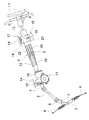
- FIG. 1 is a perspective view showing an example of an embodiment of the present invention.
- FIG. 2 is an AA enlarged cross-sectional view of FIG. 1 with some components omitted or simplified.
- FIG. 3 is a perspective view of an example of an embodiment of the present invention as seen from above with some components including a support bracket removed.
- FIG. 4 shows an example of an embodiment of the present invention in which a part including the support bracket is removed and the adjustment lever is rotated in a direction to reduce the distance between the pair of pressing portions.
- FIG. FIG. 5 is an enlarged view of the middle part of FIG.
- FIG. 6 is a view similar to FIG. 5, showing an example of an embodiment of the present invention in a state where the adjustment lever is rotated in a direction in which the distance between the pair of pressing portions is increased.
- FIG. 7 is a view similar to FIG. 6, showing an example of an embodiment of the present invention in a state where the outer column is displaced to a position where the position of the outer column can be adjusted.
- 8 is a cross-sectional view taken along the line BB in FIG.
- FIG. 9 is a perspective view of a stopper member applied to an example of an embodiment of the present invention.
- FIG. 10 is a partially cut side view showing an example of a steering device having a conventional structure.
- the steering device includes a steering column 6a, a pair of clamped portions 13a, a pair of telescopic adjustment long holes 23a, a steering shaft 5a, a support bracket 15a, and a pair of vehicle body side through holes.
- the steering column 6a is made of a metal such as an iron-based alloy or an aluminum-based alloy, and includes a cylindrical inner column 21a and a cylindrical outer column 22a.
- the rear portion of the inner column 21a disposed on the front side, It is configured by fitting the front part of the outer column 22a arranged on the side so as to allow displacement in the axial direction.
- a slit 29 extending in the axial direction is provided at an upper portion or a lower portion (upper portion in the illustrated example) of the outer column 22a, and the outer column 22a has a diameter of the front portion of the outer column 22a by the slit 29a. Is configured to be elastically scalable.
- a housing 10a made of metal such as iron-based alloy or aluminum-based alloy or synthetic resin is coupled and fixed to the front end portion of the inner column 21a.
- the housing 10a houses a speed reducer, a torque measuring device, and the like, which are components of the electric power steering device, and an electric motor 11 that is a power source of the electric power steering device is supported.
- the housing 10a is supported with respect to the vehicle body by a tilting pivot shaft such as a bolt inserted through a support tube 30 disposed in the width direction at the upper front end of the housing 10a.
- the housing 10a and the inner column 21a are attached to the vehicle body, and the front and rear positions with respect to the vehicle body are restricted.
- the housing 10a corresponds to the fixing member of the present invention.
- the fixing member may be any known structure that can be fixed to the inner column 21a and can be supported with respect to the vehicle body in a state where the front-rear position with respect to the vehicle body is regulated together with the inner column 21a.
- the pair of sandwiched portions 13a are integrally formed with the outer column 22a at two positions in the width direction that sandwich the slit 29 from both sides in the width direction on the upper surface of the front portion of the outer column 22a.
- the pair of telescopic adjustment long holes 23a is provided in a state where the pair of sandwiched portions 13a are aligned with each other so as to extend in the axial direction of the outer column 22a.
- a pair of stopper pieces 31 is provided in a state of projecting inward in the width direction.
- the lower ends of the pair of stopper pieces 31 are coupled to the upper surface of the outer column 22a, and together with the outer column 22a when adjusting the front / rear position of the steering wheel 1 (see FIG. 10) or during a secondary collision. Displace forward. That is, the pair of stopper pieces 31 corresponds to a portion displaced forward together with the outer column of the present invention.
- the steering shaft 5a enables transmission of torque by non-circular fitting such as spline engagement between the rear part of the inner shaft 19a arranged on the front side and the front part of the outer shaft 20a arranged on the rear side. And it has the structure which combined the displacement of an axial direction possible, and is rotatably supported inside the steering column 6a.
- the inner shaft 19a is supported on the inner side of the inner column 21a by a rolling bearing capable of supporting a radial load and a thrust load, such as a single row deep groove type ball bearing, so that only the rotation is possible.
- the outer shaft 20a is supported on the inner side of the outer column 22a by a rolling bearing capable of supporting a radial load and a thrust load, such as a single-row deep groove ball bearing, so that only the rotation is possible. Therefore, the steering shaft 5a expands and contracts with the expansion and contraction of the steering column 6a.
- the steering wheel 1 is supported and fixed at a portion protruding rearward from the rear end opening of the outer column 22a at the rear end portion of the outer shaft 20a.
- the support bracket 15a is provided in a state where it hangs down from the lower surface of the mounting plate 32 and the mounting plate 32 supported so as to be disengaged (displaced) forward by an impact load applied during a secondary collision. And a pair of support plate portions 16a substantially parallel to each other.
- the mounting plate portion 32 has a pair of locking notches 34 formed at both ends in the width direction of the mounting plate portion 32 so as to open to the rear end edge of the mounting plate portion 32.
- the pair of support plate portions 16a is disposed at a position where the pair of sandwiched portions 13a are sandwiched from both sides in the width direction.
- the support bracket 15a is based on an impact load associated with the secondary collision when the secondary collision occurs so that the steering column 6a can be held with sufficient rigidity at a normal time before the secondary collision occurs with respect to the vehicle body. It is supported so that it can be removed forward.
- the pair of locking members 33 has a pair of through holes 35 formed at the center in the width direction of the pair of locking members 33, and a pair of bolts or studs inserted through the pair of through holes 35. Thus, the pair of locking notches 34 are locked to the pair of locking members 33.
- a forward impact load is applied to the support bracket 15a at the time of the occurrence of the secondary collision, the pair of locking members 33 are pulled out rearward from the pair of locking notches 34, and the support bracket 15a is against the vehicle body.
- the load required for the support bracket 15a to move forward in other words, the support strength of the support bracket 15a with respect to the vehicle body is, for example, an engagement portion between a pair of locking notches 34 and a pair of locking members 33. It can be adjusted by changing the frictional force acting on.
- the support bracket 15a and the pair of locking members 33 are provided so as to span a resin pin that breaks when the support bracket 15a is detached forward, the number of pins, the diameter, and the material By changing the above, it is possible to adjust the support strength of the support bracket 15a with respect to the vehicle body.
- the shock absorbing member When a metal shock absorbing member that is plastically deformed as the support bracket 15a is moved forward is provided between the support bracket 15a and the pair of locking members 33, the shock absorbing member The support strength of the support bracket 15a with respect to the vehicle body can be adjusted by changing the shape and material.
- the pair of tilt adjusting long holes 18a are formed in an arc shape centering on the tilt pivot inserted into the support tube 30 in a state of extending in the vertical direction in the mutually aligned portions of the pair of support plate portions 16a.
- the pair of tilt adjusting long holes 18a may be formed in a state of extending vertically in a tangential direction of an arc centering on the tilt pivot.
- the adjusting rod 17a is arranged in a state where the pair of telescopic adjustment long holes 23a and the pair of tilt adjustment long holes 18a are inserted in the width direction.
- the pair of pressing portions 24a and 24b are provided at portions projecting from the outer surfaces of the pair of support plate portions 16a at both ends of the adjustment rod 17a.
- the expansion / contraction device is configured to expand / contract the space between the pair of pressing portions 24a, 24b as the adjustment lever 25 provided at one end of the adjustment rod 17a rotates.
- a cam device constituted by a driving cam and a driven cam a screw device constituted by a bolt and a nut, or the like can be adopted.
- the cam member 27 is externally fitted and fixed to a portion of the adjusting rod 17a located between the pair of sandwiched portions 13a at the intermediate portion in the axial direction of the adjusting rod 17a, and the shape seen from the width direction is oval. In the form, it has the front-end
- the shape of the cam member 27 is not limited to the oval shape as illustrated.
- the cam member 27 is configured by a pin portion that protrudes radially outward at one circumferential position, and the pin portion has another protrusion amount in the radial direction from the outer peripheral surface of the adjustment rod 17a.
- the tip of the cam member 27 is tilted upward and rearward when the adjustment lever 25 is rotated upward to the position shown in FIGS. 4 and 5 and the steering wheel 1 is held at the adjusted position.
- the adjustment lever 25 is rotated downward to the position shown in FIGS. 6 and 7 so that the position of the steering wheel 1 can be adjusted, the state is turned rearward.
- the stopper member 28 is integrally made of synthetic resin, and includes a stopper main body 36 disposed on the front side and a lift portion 37 disposed on the rear side, and includes a front half of the steering column 6a. It is provided at a position facing the upper surface of the part.
- the stopper body 36 is a long rectangular plate extending in the front-rear direction, which is a direction substantially parallel to the central axis of the steering column 6a, and includes a first buffer portion 38, a narrow portion 39, a first through hole 40, A pair of stopper surfaces 41.
- the first buffer portion 38 penetrates in the widthwise middle portion and both widthwise end portions of the lengthwise middle portion of the stopper body 36 in the up-down direction or in the up-down direction and opens on both sides in the width direction. By forming a plurality of thinned portions, it is provided in the intermediate portion in the length direction of the stopper main body 36, and is more easily elastically deformed in the length direction than other portions of the stopper main body 36. Yes.
- the narrow portion 39 is provided at the front end portion of the stopper body 36 and has a narrower width dimension than the portion adjacent to the rear side.
- the first through hole 40 has a circular cross-sectional shape, and is provided in the narrow portion 39 in the width direction.
- the pair of stopper surfaces 41 are provided at both ends in the width direction of the rear end surface of the stopper main body 36, and are disposed in the same virtual plane perpendicular to the length direction of the stopper main body 36.
- the lift portion 37 is provided in a state of extending rearward from a central portion in the width direction, which is a portion sandwiched between the pair of stopper surfaces 41 among the rear end surface of the stopper main body 36.
- the lift part 37 includes a second buffer part 42 at the front end.
- the second buffer portion 42 is formed in a waveform in the vertical direction, and is longer in the length direction than the other portions of the lift portion 37 and the portions other than the first buffer portion 38 in the stopper main body 36. It is easy to compressively deform elastically.
- parts other than the second buffer part 42 are provided in a state of extending rearward from the upper end part of the rear end surface of the second buffer part 42, and are configured in a long rectangular plate shape. .
- an urging spring 43 which is a leaf spring made of the same type of synthetic resin as the stopper member 28, is provided at the foremost portion of the narrow portion 39 constituting the front end portion of the stopper member 28. And is provided integrally.
- the urging spring 43 is folded up 180 degrees from the upper end portion of the upright plate portion 44 to the front, and the upright plate portion 44 having a long rectangular plate shape that is bent at a right angle upward from the foremost portion of the narrow portion 39.
- the semicircular arc plate-like folded plate portion 45, the short rectangular plate-like hanging plate portion 46 suspended from the front end portion of the folded plate portion 45, and the lower plate portion 46 are bent at right angles toward the front. It is comprised from the overhanging plate part 47 of the short rectangular plate shape provided.
- a pair of fixing plates 49 that are parallel to each other protrude from the rear end surface of the housing 10a near the upper end of the central portion in the width direction so as to be spaced apart in the width direction.
- a pair of second through holes 50 having a circular cross-sectional shape are provided concentrically with each other in a portion of the pair of fixed plates 49 aligned with each other.
- the front end portion of the stopper member 28 includes a first through hole 40 provided in the narrow portion 39 and a pair of second holes in a state where the narrow portion 39 is disposed between the pair of fixing plates 49.
- the pin 48 which is a pivot for stopper is installed in a state of being hung over the through hole 50, so that it is pivotally supported with respect to the rear end portion of the housing 10a.
- both ends of the pin 48 are fitted and fixed to the pair of second through holes 50 by press fitting, and the intermediate part of the pin 48 is formed with a pivot through hole. It passes through a certain first through hole 40 loosely.
- the intermediate portion of the pin 48 is fitted and fixed to the first through hole 40 by press fitting, and both ends of the pin 48 are connected to a pair of pivot through holes.
- the second hole 50 is loosely inserted.
- the pin 48 can be provided integrally with the stopper member 28, that is, can be made of a synthetic resin constituting the stopper member 28.
- the outer peripheral surface of the pin 48 is the first through hole 40 or the pair of second through holes 50, which are through holes for pivots.
- the outer diameter of the pin 48 and the inner diameter of the first through-hole 40 or the pair of second through-holes 50 are regulated so as not to be strongly pressed against the inner peripheral surface of the first through-hole.
- the lower surface of the lift portion 37 is pressed against the outer peripheral surface of the cam member 27 with a light force and the front end portion of the overhang plate portion 47 constituting the biasing spring 43. Is pressed against the upper end of the rear end surface of the housing 10a based on the elasticity of the biasing spring 43.
- the pressing force based on the elastic force of the urging spring 43 is converted into a force that swings the stopper member 28 toward the steering column 6 a around the pin 48, and the lower surface of the lift portion 37 is elastic to the outer peripheral surface of the cam member 27. Pressed against.
- the elastic force of the second buffer portion 42 constituting the stopper member 28 is also elastically applied to the lower surface of the lift portion 37 against the outer peripheral surface of the cam member 27. Acts as a force to press against.
- the force that elastically presses the lower surface of the lift portion 37 against the outer peripheral surface of the cam member 27 is such that the front-rear direction displacement of the outer column 22a is not hindered when the front-rear position of the steering wheel 1 is adjusted. It is getting smaller.
- the biasing spring 43 is formed integrally with the stopper member 28, the cost is reduced and the assemblability is improved by reducing the number of parts.
- the adjustment lever 25 When adjusting the vertical position or the front-rear position of the steering wheel 1, the adjustment lever 25 is rotated downward from the position shown in FIGS. 4 and 5 to the position shown in FIGS. 6 and 7, and the expansion / contraction device is operated. By doing so, the space
- the position of the steering wheel 1 can be adjusted within a range in which the adjustment rod 17a can be displaced within the pair of telescopic adjustment long holes 23a and the pair of tilt adjustment long holes 18a.
- the adjustment lever 25 is pivoted upward from the position shown in FIGS. 6 and 7 to the position shown in FIGS. 4 and 5 and the expansion / contraction device is operated, whereby the pair of pressing portions 24a and 24b. The distance between them is reduced.
- the rear end of the pair of telescopic adjustment long holes 23a is the outer periphery of the adjustment rod 17a.
- the front end surfaces of the pair of stopper pieces 31 collide (contact) with the pair of stopper surfaces 41, and the stopper main body 36 constituting the stopper member 28 is in contact with the rear end surface of the housing 10a. It is clamped in the front-rear direction between the front end surfaces of the pair of stopper pieces 31. That is, the position where the front end face of the pair of stopper pieces 31 and the pair of stopper faces 41 collide becomes the front end position of the position adjustable range of the steering wheel 1.
- the adjustment lever 25 is rotated downward to the position shown in FIGS. 6 and 7, and the pair of pressing portions 24a, 24b is moved by the expansion / contraction device.
- the outer column 22a is displaced forward by displacing the steering wheel 1, as shown in FIG. 7, the rear end portion of the pair of telescopic adjustment long holes 23a becomes the adjustment rod 17a.
- the stopper body 36 contacts the rear end surface of the housing 10a and the pair of stopper pieces 31. Between the front end surfaces of the pair of telescopic adjustment holes 17a and the outer end surface of the adjustment rod 17a is prevented from colliding with each other. In a state where the front end surfaces of the pair of stopper pieces 31 collide with the pair of stopper surfaces 41, the forwardly applied force applied from the steering wheel 1 to the outer column 22a is supported on the vehicle body via the stopper body 36 and the housing 10a. Is done.
- the stopper member 28 includes a stopper body 36 disposed on the front side and a lift portion 37 disposed on the rear side, and only the stopper body 36 is a pair of stopper pieces with the rear end surface of the housing 10a. It is clamped in the front-rear direction between the front end surfaces of 31. Accordingly, the entire long stopper member 28 is sandwiched in the front-rear direction as compared with the case where a configuration is employed in which the entire stopper member 28 is sandwiched in the front-rear direction between the rear end surface of the housing 10a and the front end surfaces of the pair of stopper pieces 31.
- the buckling strength of the portion to be increased can be increased.
- the stopper body 36 is sandwiched in the front-rear direction between the rear end surface of the housing 10a and the front end surfaces of the pair of stopper pieces 31, that is, the front end surface of the stopper member 28 abuts the rear end surface of the housing 10a. Even in this state, since the outer peripheral surface of the pin 48 is not strongly pressed against the inner peripheral surface of the first through hole 40 or the second through hole 50 that is the through hole for the pivot shaft, the pin 48 and the pair of fixing members are fixed. The plate 49 is prevented from being damaged.
- the adjustment lever 25 In order to hold the steering wheel 1 in the adjusted position, the adjustment lever 25 is rotated upward to the position shown in FIGS. 4 and 5, and the space between the pair of pressing portions 24 a and 24 b is increased by the expansion / contraction device. In the contracted state, the entire pair of stopper surfaces 41 is positioned above the front end surfaces of the pair of stopper pieces 31. Therefore, even when the outer column 22a is displaced forward due to the impact load at the time of the secondary collision, the front end surfaces of the pair of stopper pieces 31 are prevented from colliding with the pair of stopper surfaces 41, and a pair of telescopic The rear end portion of the adjustment long hole 23aa is allowed to contact the adjustment rod 17a.
- the impact load at the time of the secondary collision can be transmitted to the support bracket 15a via the adjustment rod 17a, and the impact load applied to the driver by moving the support bracket 15a forward (displaced) with respect to the vehicle body. Can be relaxed.
- the front-rear position of the steering wheel 1 even if the steering wheel 1 is vigorously displaced to the front end position, it is possible to prevent a forward impact from being applied to the support bracket 15a.
- the cam member 27 may collide with the lower end portion or the middle portion of the rear end surface of the second buffer portion 42 that constitutes the stopper member 28 in the process in which the support bracket 15a is displaced forward with respect to the vehicle body.
- the second buffer portion 42 and the first buffer portion 38 are elastically compressed in the front-rear direction, and the impact due to the collision can be mitigated.
- the front end surface or the upper surface of the cam member 27 is inclined in the upward direction as it goes backward as shown in FIG. . For this reason, immediately after the collision occurs, the second buffer portion 42 smoothly rides on the upper surface of the cam member 27, and the forward displacement of the support bracket 15a is continuously allowed.
- the structure of the portion that supports the support bracket so as to be able to be detached forward based on the impact load applied to the vehicle body at the time of the secondary collision is not particularly limited.
- a structure in which one locking member is locked in a locking notch provided at a location may be employed.
- a pair of sandwiched portions are formed by bulging the front end portion of the outer column radially outward, and the outer column
- a structure in which a spacer for preventing rattling is provided between the inner column and the inner column may be employed.
- the present invention can also be applied to a steering device having only a telescopic mechanism of a telescopic mechanism and a tilt mechanism.
- the pair of vehicle body side through holes are formed by circular holes through which the adjustment rods can be inserted.
- the structure of the urging means is not particularly limited as long as the stopper member can be urged toward the steering column in the vertical direction.
- the urging means is an elastic member
- various shapes can be adopted as the elastic member, and the elastic member can be formed integrally with the stopper member or formed separately from the stopper member. You can also.
- a pair of sandwiched portions 13a is provided at two positions spaced apart in the width direction of the upper surface of the outer column 22a, and the adjustment rod 17a is disposed above the outer column 22a. It arrange
- the pair of sandwiched portions are provided integrally with the outer column at two positions spaced apart in the width direction of the lower surface of the outer column, and the adjustment rod is disposed below the outer column.
- the present invention can also be applied to a steering apparatus having a structure that is inserted through a telescopic adjustment long hole of the sandwiched portion. In this case, the arrangement and direction of the pair of pressing portions, the expansion / contraction device, the cam member, and the stopper member constituting the present invention are reversed in the vertical direction.
Landscapes
- Engineering & Computer Science (AREA)
- Mechanical Engineering (AREA)
- Chemical & Material Sciences (AREA)
- Combustion & Propulsion (AREA)
- Transportation (AREA)
- General Engineering & Computer Science (AREA)
- Steering Controls (AREA)
Abstract
Description
2 ステアリングギヤユニット
3 入力軸
4 タイロッド
5、5a ステアリングシャフト
6、6a ステアリングコラム
7 自在継手
8 中間シャフト
9 自在継手
10、10a ハウジング
11 電動モータ
12 チルト用枢軸
13、13a 被挟持部
14 車体
15、15a 支持ブラケット
16、16a 支持板部
17、17a 調節ロッド
18、18a チルト調節用長孔
19、19a インナシャフト
20、20a アウタシャフト
21、21a インナコラム
22、22a アウタコラム
23、23a テレスコ調節用長孔
24a、24b 押圧部
25 調節レバー
27 カム部材
28 ストッパ部材
29 スリット
30 支持管
31 ストッパ片
32 取付板部
33 係止部材
34 係止切り欠き
35 通孔
36 ストッパ本体
37 リフト部
38 第1緩衝部
39 幅狭部
40 第1通孔
41 ストッパ面
42 第2緩衝部
43 付勢ばね
44 起立板部
45 折り返し板部
46 垂下板部
47 張り出し板部
48 ピン
49 固定板
50 第2通孔
Claims (8)
- ステアリングコラムと、1対の被挟持部と、1対のテレスコ調節用長孔と、支持ブラケットと、1対の車体側貫通孔と、調節ロッドと、1対の押圧部と、拡縮装置と、カム部材と、固定部材と、ストッパ部材とを備え、
前記ステアリングコラムは、インナコラムとアウタコラムとを有し、該インナコラムの後部と該アウタコラムの前部とを、軸方向の相対変位を可能に嵌合することにより構成され、かつ、内側に、伸縮可能なステアリングシャフトが回転自在に支持可能であり、
前記1対の被挟持部は、前記アウタコラムの上面または下面の幅方向に離隔した2箇所位置に、該アウタコラムと一体に設けられており、
前記1対のテレスコ調節用長孔は、前記1対の被挟持部の互いに整合する部分に、前記アウタコラムの軸方向に伸長する状態で設けられており、
前記支持ブラケットは、前記1対の被挟持部を幅方向両側から挟む1対の支持板部を有し、車体に対し、二次衝突時に加わる荷重に基づいて前方への離脱を可能に支持されており、
前記1対の車体側貫通孔は、前記1対の支持板部の互いに整合する部分に設けられており、
前記調節ロッドは、前記1対のテレスコ調節用長孔と前記1対の車体側貫通孔とを幅方向に挿通する状態で設けられており、
前記1対の押圧部は、前記調節ロッドの両端部で、前記1対の支持板部の外側面から突出した部分に設けられており、
前記拡縮装置は、前記1対の押圧部同士の間隔を拡縮するものであり、
前記カム部材は、前記調節ロッドのうち、該調節ロッドの軸方向中間部で前記1対の被挟持部同士の間に位置する部分に固定されており、
前記固定部材は、前記車体に対する前後位置を規制された状態で設けられており、
前記ストッパ部材は、前記固定部材に支持された状態で後方に向いたストッパ面と、前記固定部材に支持された状態で前記ステアリングコラムの外周面と対向し、かつ、前記カム部材の外周面に当接する上下方向片側面とを有し、および、前記拡縮装置により前記1対の押圧部同士の間隔を拡げた状態で、前記ストッパ面が、前記カム部材により前記ステアリングコラム側に変位させられ、前記アウタコラムが前方に変位した場合において、前記1対のテレスコ調節用長孔の後端部と前記調節ロッドの外周面とが衝突する以前に、前記ストッパ面と前記アウタコラムとともに前方に変位する部分とが衝突し、前記拡縮装置により前記1対の押圧部同士の間隔を縮めた状態では、前記ストッパ面が、前記カム部材により前記ステアリングコラムから離れる方向に変位させられ、前記アウタコラムが前方に変位した場合でも、前記1対のテレスコ調節用長孔の後端部と前記調節ロッドの外周面とが衝突する以前に、前記ストッパ面と前記アウタコラムとともに前方に変位する部分とが衝突することがないように、構成されている、
ステアリング装置。 - 前記固定部材は、前記インナコラムの前側に配置され、
前記ストッパ部材は、前端部と後端面を有するストッパ本体を備え、前記ストッパ面は、該ストッパ本体の後端面に設けられており、前記ストッパ本体の前端部は前記固定部材に対し支持されており、
前記ストッパ面と前記アウタコラムとともに前方に変位する部分とが衝突した状態で、前記ストッパ本体が、該アウタコラムとともに前方に変位する部分と前記固定部材との間で前後方向に挟持される、
請求項1に記載のステアリング装置。 - 前記ストッパ部材は、前記ストッパ本体の後端面のうち、前記ストッパ面から外れた部分から後方に延出する状態で設けられたリフト部を備え、前記ストッパ部材の上下方向片側面が、該リフト部に設けられている、請求項2に記載のステアリング装置。
- 前記ストッパ部材は、付勢手段を有し、該ストッパ部材は、該付勢手段により上下方向に関して前記ステアリングコラム側に付勢されている、
請求項1に記載のステアリング装置。 - 前記ストッパ部材は、幅方向に配設されたストッパ用枢軸により前記固定部材に対し枢動可能に支持されており、
前記ストッパ部材は、前記付勢手段により、前記ストッパ用枢軸を中心として前記ステアリングコラム側に揺動する方向に付勢されている、
請求項4に記載のステアリング装置。 - 前記付勢手段は、前記ストッパ部材と前記固定部材との間に設けられた弾性部材である、請求項5に記載のステアリング装置。
- 前記弾性部材が、前記ストッパ部材と一体に設けられている、請求項6に記載のステアリング装置。
- 前記ストッパ部材は、前記アウタコラムとともに前方に変位する部分と前記ストッパ面とが衝突する際に加わる衝撃と、二次衝突時に前記カム部材と前記ストッパ部材とが衝突する際に加わる衝撃とのうちの、少なくとも一方の衝撃が加わった場合に、他の部分に比べて大きく弾性変形する緩衝部を有している、請求項1に記載のステアリング装置。
Priority Applications (4)
| Application Number | Priority Date | Filing Date | Title |
|---|---|---|---|
| US15/127,905 US10086865B2 (en) | 2015-01-14 | 2016-01-14 | Steering device |
| CN201680005821.1A CN107107946B (zh) | 2015-01-14 | 2016-01-14 | 转向装置 |
| EP16737437.0A EP3225505B1 (en) | 2015-01-14 | 2016-01-14 | Steering device |
| JP2016530024A JP5975199B1 (ja) | 2015-01-14 | 2016-01-14 | ステアリング装置 |
Applications Claiming Priority (2)
| Application Number | Priority Date | Filing Date | Title |
|---|---|---|---|
| JP2015-005129 | 2015-01-14 | ||
| JP2015005129 | 2015-01-14 |
Publications (1)
| Publication Number | Publication Date |
|---|---|
| WO2016114366A1 true WO2016114366A1 (ja) | 2016-07-21 |
Family
ID=56405906
Family Applications (1)
| Application Number | Title | Priority Date | Filing Date |
|---|---|---|---|
| PCT/JP2016/051035 WO2016114366A1 (ja) | 2015-01-14 | 2016-01-14 | ステアリング装置 |
Country Status (5)
| Country | Link |
|---|---|
| US (1) | US10086865B2 (ja) |
| EP (1) | EP3225505B1 (ja) |
| JP (1) | JP5975199B1 (ja) |
| CN (1) | CN107107946B (ja) |
| WO (1) | WO2016114366A1 (ja) |
Families Citing this family (4)
| Publication number | Priority date | Publication date | Assignee | Title |
|---|---|---|---|---|
| DE102015216536B3 (de) * | 2015-08-28 | 2017-02-16 | Thyssenkrupp Ag | Klemmvorrichtung einer verstellbaren Lenksäule für Kraftfahrzeuge |
| JP6905918B2 (ja) * | 2017-11-17 | 2021-07-21 | 株式会社山田製作所 | ステアリング装置 |
| KR102398780B1 (ko) * | 2018-03-28 | 2022-05-17 | 남양넥스모 주식회사 | 스티어링 칼럼 |
| US10858032B2 (en) * | 2018-11-29 | 2020-12-08 | Steering Solutions Ip Holding Corporation | Clamp load adjustment assembly for steering column |
Citations (5)
| Publication number | Priority date | Publication date | Assignee | Title |
|---|---|---|---|---|
| JP2008308072A (ja) * | 2007-06-15 | 2008-12-25 | Mitsubishi Motors Corp | ステアリングコラム装置の衝撃吸収構造 |
| US20110210536A1 (en) * | 2008-06-04 | 2011-09-01 | Zf Systemes De Direction Nacam Sas | Adjustable steering column for motor vehicles |
| JP2013124079A (ja) * | 2011-12-16 | 2013-06-24 | Nsk Ltd | 車両用位置調整式ステアリングコラム装置 |
| JP2014051129A (ja) * | 2012-09-05 | 2014-03-20 | Kayaba Ind Co Ltd | ステアリング装置 |
| JP2014129087A (ja) * | 2011-04-14 | 2014-07-10 | Nsk Ltd | ステアリング装置 |
Family Cites Families (31)
| Publication number | Priority date | Publication date | Assignee | Title |
|---|---|---|---|---|
| ES2161127B1 (es) * | 1999-03-16 | 2002-09-01 | Castellon Melchor Daumal | Arbol telescopico para columnas de direccion en vehiculos de automoviles con sistema de deslizamiento con control de carga. |
| DE10057861A1 (de) * | 2000-11-21 | 2002-05-23 | Mkl Miniaturkugellager Gmbh | Kugellager und Kugellagereinheit |
| JP4254194B2 (ja) * | 2002-10-10 | 2009-04-15 | 日本精工株式会社 | 車両ステアリング用伸縮軸 |
| JP4419841B2 (ja) * | 2002-11-29 | 2010-02-24 | 日本精工株式会社 | 車両ステアリング用伸縮軸 |
| US20070157754A1 (en) * | 2004-01-27 | 2007-07-12 | Nsk Ltd. | Telescopic shaft for vehicle steering |
| US8047096B2 (en) * | 2007-03-30 | 2011-11-01 | Nexteer (Beijing) Technology Co., Ltd. | Lock mechanism for an adjustable steering column assembly |
| JP2009090856A (ja) * | 2007-10-10 | 2009-04-30 | Nsk Ltd | ステアリング装置 |
| CN101827741B (zh) * | 2007-10-15 | 2012-05-30 | 德昌机械株式会社 | 用于车辆的伸缩轴 |
| JP5030744B2 (ja) * | 2007-11-26 | 2012-09-19 | Ntn株式会社 | 軸受装置 |
| CN102009684B (zh) * | 2009-05-29 | 2013-06-19 | 通用汽车环球科技运作公司 | 用于可折叠转向柱组件的能量吸收装置 |
| JP5327179B2 (ja) | 2010-10-15 | 2013-10-30 | 日本精工株式会社 | ステアリングコラム用支持装置 |
| JP2012167814A (ja) * | 2011-01-25 | 2012-09-06 | Nsk Ltd | 転がり軸受 |
| JP5609838B2 (ja) | 2011-06-16 | 2014-10-22 | 日本精工株式会社 | ステアリングコラム装置 |
| JP5917030B2 (ja) * | 2011-06-30 | 2016-05-11 | Ntn株式会社 | 転がり軸受 |
| JP5865805B2 (ja) * | 2012-09-05 | 2016-02-17 | Kyb株式会社 | ステアリング装置 |
| JP2015044507A (ja) * | 2013-07-31 | 2015-03-12 | 株式会社ジェイテクト | ステアリング装置 |
| JP6473741B2 (ja) * | 2013-10-04 | 2019-02-20 | エヌエスケイ アメリカズ インコーポレイテッド | コラプシブルステアリングコラムアセンブリ |
| US9421995B2 (en) * | 2013-10-30 | 2016-08-23 | Nsk Ltd. | Steering device |
| DE102014101194B4 (de) * | 2014-01-31 | 2015-09-10 | Thyssenkrupp Ag | Lenkwelle für ein Kraftfahrzeug |
| DE102014105822B4 (de) * | 2014-04-25 | 2016-03-03 | Thyssenkrupp Presta Ag | Lenkwelle für ein Kraftfahrzeug |
| GB201411629D0 (en) * | 2014-06-30 | 2014-08-13 | Trw Ltd | Telescopic steering column assembly |
| CN106062397B (zh) * | 2014-07-03 | 2019-11-15 | 日本精工株式会社 | 伸缩式旋转传递轴 |
| WO2016076266A1 (ja) * | 2014-11-10 | 2016-05-19 | 日本精工株式会社 | 衝撃吸収式ステアリング装置 |
| JP5999283B1 (ja) * | 2014-12-18 | 2016-09-28 | 日本精工株式会社 | ステアリング装置 |
| US9849906B2 (en) * | 2015-03-27 | 2017-12-26 | Fuji Kiko Co., Ltd. | Steering column device |
| JP5980992B1 (ja) * | 2015-06-04 | 2016-08-31 | Dmg森精機株式会社 | 工作機械の軸受潤滑装置 |
| JP6604162B2 (ja) * | 2015-11-25 | 2019-11-13 | 株式会社ジェイテクト | 遊星ローラ式変速機及びその組立方法並びにその取付方法 |
| JP6642827B2 (ja) * | 2016-02-12 | 2020-02-12 | 株式会社ジェイテクト | ステアリング装置 |
| JP6694739B2 (ja) * | 2016-03-25 | 2020-05-20 | 富士機工株式会社 | ステアリングコラム装置 |
| KR101639036B1 (ko) * | 2016-04-25 | 2016-07-12 | 서한산업(주) | 길이 가변형 샤프트 |
| DE102016224271A1 (de) * | 2016-12-06 | 2017-02-02 | Thyssenkrupp Ag | Lenkwelle für ein Kraftfahrzeug |
-
2016
- 2016-01-14 CN CN201680005821.1A patent/CN107107946B/zh active Active
- 2016-01-14 JP JP2016530024A patent/JP5975199B1/ja active Active
- 2016-01-14 US US15/127,905 patent/US10086865B2/en active Active
- 2016-01-14 EP EP16737437.0A patent/EP3225505B1/en active Active
- 2016-01-14 WO PCT/JP2016/051035 patent/WO2016114366A1/ja active Application Filing
Patent Citations (5)
| Publication number | Priority date | Publication date | Assignee | Title |
|---|---|---|---|---|
| JP2008308072A (ja) * | 2007-06-15 | 2008-12-25 | Mitsubishi Motors Corp | ステアリングコラム装置の衝撃吸収構造 |
| US20110210536A1 (en) * | 2008-06-04 | 2011-09-01 | Zf Systemes De Direction Nacam Sas | Adjustable steering column for motor vehicles |
| JP2014129087A (ja) * | 2011-04-14 | 2014-07-10 | Nsk Ltd | ステアリング装置 |
| JP2013124079A (ja) * | 2011-12-16 | 2013-06-24 | Nsk Ltd | 車両用位置調整式ステアリングコラム装置 |
| JP2014051129A (ja) * | 2012-09-05 | 2014-03-20 | Kayaba Ind Co Ltd | ステアリング装置 |
Non-Patent Citations (1)
| Title |
|---|
| See also references of EP3225505A4 * |
Also Published As
| Publication number | Publication date |
|---|---|
| US20170355393A1 (en) | 2017-12-14 |
| EP3225505A1 (en) | 2017-10-04 |
| US10086865B2 (en) | 2018-10-02 |
| CN107107946A (zh) | 2017-08-29 |
| CN107107946B (zh) | 2018-07-10 |
| JPWO2016114366A1 (ja) | 2017-04-27 |
| EP3225505B1 (en) | 2018-12-26 |
| JP5975199B1 (ja) | 2016-08-23 |
| EP3225505A4 (en) | 2018-01-10 |
Similar Documents
| Publication | Publication Date | Title |
|---|---|---|
| JP5812194B2 (ja) | 電動ステアリングホイールの位置調節装置 | |
| JP5070795B2 (ja) | ステアリングホイールの位置調節装置 | |
| JP5975199B1 (ja) | ステアリング装置 | |
| JP5382066B2 (ja) | ステアリング装置 | |
| JP6142967B2 (ja) | テレスコピック式ステアリング装置 | |
| JP6048617B2 (ja) | ステアリングホイールの位置調節装置 | |
| JP5737456B2 (ja) | ステアリングコラムおよびテレスコピック式ステアリング装置 | |
| WO2015133017A1 (ja) | テレスコピックステアリング装置用アウタコラム及びテレスコピックステアリング装置 | |
| JP5891876B2 (ja) | ステアリング装置 | |
| JPWO2017069186A1 (ja) | ブラケット付アウタコラム、ブラケット付ステアリングコラム、及びステアリング装置 | |
| JP7310166B2 (ja) | ステアリングコラム装置 | |
| JP2018024400A (ja) | テレスコピックステアリングコラム及びステアリングホイールの位置調節装置 | |
| JP6668619B2 (ja) | テレスコピック式ステアリングコラム装置 | |
| JP6379863B2 (ja) | ステアリングホイールの位置調節装置及びその製造方法 | |
| JP6384225B2 (ja) | ステアリングコラム用支持装置 | |
| JP5895754B2 (ja) | ステアリングホイールの位置調節装置 | |
| JP6098745B2 (ja) | ステアリング装置 | |
| JP2016222056A (ja) | チルト式ステアリングコラム装置 | |
| JP2016068589A (ja) | ステアリングコラム用支持装置 | |
| JP2016047669A5 (ja) | ||
| JP2015107801A (ja) | チルト式ステアリング装置 | |
| JP6406020B2 (ja) | ステアリングホイールの位置調節装置 | |
| JP2016032955A (ja) | テレスコピックステアリングコラム及びステアリングホイールの前後位置調節装置 | |
| JP6094177B2 (ja) | ステアリングホイールの位置調節装置 | |
| JP5692257B2 (ja) | チルト式ステアリング装置 |
Legal Events
| Date | Code | Title | Description |
|---|---|---|---|
| ENP | Entry into the national phase |
Ref document number: 2016530024 Country of ref document: JP Kind code of ref document: A |
|
| 121 | Ep: the epo has been informed by wipo that ep was designated in this application |
Ref document number: 16737437 Country of ref document: EP Kind code of ref document: A1 |
|
| WWE | Wipo information: entry into national phase |
Ref document number: 15127905 Country of ref document: US |
|
| REEP | Request for entry into the european phase |
Ref document number: 2016737437 Country of ref document: EP |
|
| NENP | Non-entry into the national phase |
Ref country code: DE |