WO2016111325A1 - 液滴検出装置およびインクジェットプリンター - Google Patents
液滴検出装置およびインクジェットプリンター Download PDFInfo
- Publication number
- WO2016111325A1 WO2016111325A1 PCT/JP2016/050328 JP2016050328W WO2016111325A1 WO 2016111325 A1 WO2016111325 A1 WO 2016111325A1 JP 2016050328 W JP2016050328 W JP 2016050328W WO 2016111325 A1 WO2016111325 A1 WO 2016111325A1
- Authority
- WO
- WIPO (PCT)
- Prior art keywords
- pair
- light
- droplet
- arrow
- wall portions
- Prior art date
- Legal status (The legal status is an assumption and is not a legal conclusion. Google has not performed a legal analysis and makes no representation as to the accuracy of the status listed.)
- Ceased
Links
Images




Classifications
-
- B—PERFORMING OPERATIONS; TRANSPORTING
- B41—PRINTING; LINING MACHINES; TYPEWRITERS; STAMPS
- B41J—TYPEWRITERS; SELECTIVE PRINTING MECHANISMS, i.e. MECHANISMS PRINTING OTHERWISE THAN FROM A FORME; CORRECTION OF TYPOGRAPHICAL ERRORS
- B41J2/00—Typewriters or selective printing mechanisms characterised by the printing or marking process for which they are designed
- B41J2/005—Typewriters or selective printing mechanisms characterised by the printing or marking process for which they are designed characterised by bringing liquid or particles selectively into contact with a printing material
- B41J2/01—Ink jet
- B41J2/015—Ink jet characterised by the jet generation process
- B41J2/04—Ink jet characterised by the jet generation process generating single droplets or particles on demand
- B41J2/045—Ink jet characterised by the jet generation process generating single droplets or particles on demand by pressure, e.g. electromechanical transducers
- B41J2/04501—Control methods or devices therefor, e.g. driver circuits, control circuits
- B41J2/04561—Control methods or devices therefor, e.g. driver circuits, control circuits detecting presence or properties of a drop in flight
-
- B—PERFORMING OPERATIONS; TRANSPORTING
- B41—PRINTING; LINING MACHINES; TYPEWRITERS; STAMPS
- B41J—TYPEWRITERS; SELECTIVE PRINTING MECHANISMS, i.e. MECHANISMS PRINTING OTHERWISE THAN FROM A FORME; CORRECTION OF TYPOGRAPHICAL ERRORS
- B41J2/00—Typewriters or selective printing mechanisms characterised by the printing or marking process for which they are designed
- B41J2/005—Typewriters or selective printing mechanisms characterised by the printing or marking process for which they are designed characterised by bringing liquid or particles selectively into contact with a printing material
- B41J2/01—Ink jet
- B41J2/015—Ink jet characterised by the jet generation process
- B41J2/04—Ink jet characterised by the jet generation process generating single droplets or particles on demand
- B41J2/045—Ink jet characterised by the jet generation process generating single droplets or particles on demand by pressure, e.g. electromechanical transducers
- B41J2/04501—Control methods or devices therefor, e.g. driver circuits, control circuits
- B41J2/04586—Control methods or devices therefor, e.g. driver circuits, control circuits controlling heads of a type not covered by groups B41J2/04575 - B41J2/04585, or of an undefined type
-
- B—PERFORMING OPERATIONS; TRANSPORTING
- B41—PRINTING; LINING MACHINES; TYPEWRITERS; STAMPS
- B41J—TYPEWRITERS; SELECTIVE PRINTING MECHANISMS, i.e. MECHANISMS PRINTING OTHERWISE THAN FROM A FORME; CORRECTION OF TYPOGRAPHICAL ERRORS
- B41J2/00—Typewriters or selective printing mechanisms characterised by the printing or marking process for which they are designed
- B41J2/005—Typewriters or selective printing mechanisms characterised by the printing or marking process for which they are designed characterised by bringing liquid or particles selectively into contact with a printing material
- B41J2/01—Ink jet
- B41J2/135—Nozzles
- B41J2/165—Prevention or detection of nozzle clogging, e.g. cleaning, capping or moistening for nozzles
- B41J2/16579—Detection means therefor, e.g. for nozzle clogging
-
- B—PERFORMING OPERATIONS; TRANSPORTING
- B41—PRINTING; LINING MACHINES; TYPEWRITERS; STAMPS
- B41J—TYPEWRITERS; SELECTIVE PRINTING MECHANISMS, i.e. MECHANISMS PRINTING OTHERWISE THAN FROM A FORME; CORRECTION OF TYPOGRAPHICAL ERRORS
- B41J2/00—Typewriters or selective printing mechanisms characterised by the printing or marking process for which they are designed
- B41J2/005—Typewriters or selective printing mechanisms characterised by the printing or marking process for which they are designed characterised by bringing liquid or particles selectively into contact with a printing material
- B41J2/01—Ink jet
- B41J2/21—Ink jet for multi-colour printing
- B41J2/2132—Print quality control characterised by dot disposition, e.g. for reducing white stripes or banding
- B41J2/2142—Detection of malfunctioning nozzles
Definitions
- the present invention relates to a droplet detection device that detects minute droplets ejected from a nozzle of a head of an inkjet printer, and an inkjet printer including the droplet detection device.
- a droplet detection device that detects a minute droplet ejected from a nozzle of a head of an inkjet printer is known that includes a collimating light source (see, for example, Patent Document 1).
- the collimated light source needs to use an expensive device such as a laser. Therefore, the conventional droplet detection device has a problem that the manufacturing cost is high.
- an object of the present invention is to provide a droplet detection device and an ink jet printer that can reduce the manufacturing cost.
- the present invention is a droplet detection device that detects a droplet (micro droplet) ejected from a nozzle of a head of an inkjet printer based on whether or not the detection light is blocked by the droplet, A light emitting element that irradiates the detection light in a direction that intersects the traveling direction of the liquid droplets ejected from the nozzle; A light receiving element that receives the detection light emitted from the light emitting element; A pair of walls disposed opposite to each other with an interval through which the droplets pass, and The pair of wall portions are provided along the optical path so that at least a part of the optical path of the detection light from the light emitting element to the light receiving element passes between the pair of wall portions, In the region between the pair of wall portions in the optical path, at least a part of the detection light is guided to the light receiving element side while being reflected by the opposing surfaces of the pair of wall portions. It is characterized by.
- the pair of wall portions of the droplet detection device of the present invention have predetermined heights in orthogonal directions perpendicular to the opposing direction of the pair of wall portions and the direction along the optical path of the detection light.
- the width in the facing direction of the detection light emitted from the light emitting element is preferably equal to the interval in the facing direction of the pair of wall portions in at least a part of the range in the orthogonal direction.
- the liquid droplet detection device of the present invention in the region sandwiched between the ends of the pair of wall portions on the light emitting element side, the opposing direction of the pair of wall portions and the optical path between the pair of wall portions are aligned. Since no gap is formed between the wall portion and the detection light in the opposite direction of the pair of wall portions in at least a part of the range perpendicular to both the direction and the shadow, the shadow is caused by the pair of wall portions. It is possible to suppress the occurrence in the range between. Therefore, the liquid droplet detection device of the present invention does not include a collimating light source that uses an expensive device such as a laser, and the liquid droplet detection device in the range between the pair of wall portions, which is the micro droplet detection range. It is possible to suppress the occurrence of detection sensitivity spots and to detect minute droplets with high accuracy. Therefore, the manufacturing cost of the droplet detection device of the present invention can be reduced as compared with the related art.
- a slit for limiting the width of the detection light in the orthogonal direction is formed on the end portion side on the light emitting element side.
- the droplet detection device of the present invention can suppress the detection light emitted from the light emitting element from diffusing in the orthogonal direction while proceeding to the light receiving element side. It is possible to prevent the light from being received by the light receiving element after being diffused in the orthogonal direction while being advanced toward the light receiving element and reflected by some member. Therefore, the droplet detection device of the present invention can satisfy the detection range of the minute droplets with the detection light with the uniform amount of light by suppressing the loss of the light amount due to the diffusion of the detection light. The occurrence of unevenness in detection sensitivity can be suppressed. That is, the droplet detection apparatus of the present invention can detect a minute droplet with high accuracy.
- one end edge and the other end edge of the slit in the orthogonal direction extend linearly in the facing direction and are provided in parallel to each other, In the region between the pair of walls in the optical path,
- the width of the detection light in the facing direction is the same as the distance between the pair of walls in the entire range in the orthogonal direction,
- the width of the detection light in the orthogonal direction is preferably the same as the width of the slit in the orthogonal direction over the entire range in the facing direction.
- the droplet detection device of the present invention can suppress the occurrence of unevenness in the amount of detection light in both the opposing direction of the pair of walls and the orthogonal direction in the detection range of the minute droplets. In addition, it is possible to suppress the occurrence of spots of sensitivity for detection of microdroplets. In other words, since the droplet detection apparatus of the present invention can detect a microdroplet with high accuracy, the microdroplet can be detected accurately and easily.
- a length of the light receiving area in which the light receiving element can receive the detection light in the facing direction is greater than or equal to an interval between the pair of wall portions in the facing direction. Also good.
- the droplet detection device of the present invention can detect the entire region of the detection light between the pair of wall portions in the opposing direction of the pair of wall portions. That is, the droplet detection apparatus of the present invention can detect a minute droplet in the entire range while ensuring a wide detection range of the minute droplet.
- the droplet detection device of the present invention determines that the detection light is blocked by a droplet (micro droplet) when the amount of detection light received by the light receiving element is lower than the predetermined amount by a predetermined amount or more.
- Determination means to perform The droplets (micro droplets) are ejected in order from each of the plurality of nozzles constituting the nozzle row, and whether or not each of the plurality of nozzles is clogged is determined based on a determination result by the determination unit. And an abnormality determination means.
- An inkjet printer includes the above-described droplet detection device, and a plurality of heads each having a nozzle row in which nozzles for ejecting the droplets (microdroplets) are linearly arranged in a direction along the optical path.
- the plurality of heads includes a head located on one side in the direction along the optical path and a head located on the other side,
- the length of the pair of wall portions in the direction along the optical path is a direction along the optical path in a range where the nozzle row of the head located on the one side and the nozzle row of the head located on the other side are located. It is characterized by being longer than.
- the ink jet printer of the present invention includes the droplet detection device that can reduce the manufacturing cost as compared with the related art, and thus the manufacturing cost can be suppressed as compared with the related art.
- the inkjet printer of the present invention can suppress the occurrence of spots of sensitivity for detection of microdroplets in the detection range of microdroplets of the droplet detection device, and the detection light diffuses and the amount of light is lost. Therefore, the detection range of micro droplets by the droplet detection device in the direction in which the nozzle array of the head extends can be extended and expanded. Therefore, the ink jet printer of the present invention can detect minute droplets for all nozzles of a plurality of heads without moving the head relative to the droplet detection device in the direction in which the nozzle row extends.
- the manufacturing cost of the droplet detection device and the ink jet printer of the present invention can be reduced as compared with the related art.
- FIG. 1 is an external perspective view of an inkjet printer according to an embodiment of the present invention.
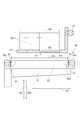
- FIG. 2 is a part of a cross-sectional view taken along the line AA shown in FIG.
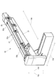
- FIG. 4 is an external perspective view of the droplet detection device shown in FIG. 3 with a cover removed. It is sectional drawing seen from the arrow 10a direction of a part of droplet detection apparatus shown in FIG.
- FIG. 4 is a plan view of a part of the droplet detection device shown in FIG. 3.
- FIG. 4 is a partial cross-sectional view of the droplet detection device shown in FIG. 3, in which the light width limiting member is viewed from the light receiving element side.
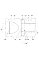
- FIG. 4 is a partial cross-sectional view of a droplet detection device as a comparative example of the droplet detection device shown in FIG. 3, and is a view of a light width limiting member viewed from the light receiving element side. It is a figure which shows an example of the map of the sensitivity in the droplet detection apparatus shown in FIG. It is a figure which shows an example of the map of the sensitivity in the droplet detection apparatus shown in FIG. (A) It is sectional drawing of a part of droplet detection apparatus shown in FIG. 3 which looked at the light width limiting member from the light receiving element side, Comprising: It is a figure which shows the example different from the example shown in FIG. (B) It is sectional drawing of a part of droplet detection apparatus shown in FIG. 3 which looked at the light width limitation member from the light receiving element side, Comprising: The example different from the example shown to (a) of FIG. 7 and FIG. 11 is shown FIG.
- FIG. 1 is an external perspective view of an inkjet printer 10 according to the present embodiment.
- the inkjet printer 10 includes a leg 11 installed on the floor, and a main body 12 supported by the leg 11 and extending in the direction of the arrow 10 a (main scanning direction). ing.
- the main body 12 is supported by the guide rail 14, a medium transport device (not shown) for transporting the medium 90 in the arrow 10 b direction (sub-scanning direction) orthogonal to the arrow 10 a direction, the guide rail 14 extending in the arrow 10 a direction, and the guide rail 14.
- a carriage 15 movably provided in the direction of the arrow 10 a (main scanning direction), a plurality of heads 16 mounted on the carriage 15 and ejecting ink toward the medium 90, and ejection from the head 16.
- 1 illustrates a droplet detection device 20 that detects minute droplets of ink to be discharged, a case 17 that covers the guide rail 14, the carriage 15, the head 16, and the droplet detection device 20, and the overall operation of the inkjet printer 10. And no control unit.
- the plurality of heads 16 are staggered. Accordingly, the plurality of heads 16 arranged side by side in the main scanning direction (arrow 10a direction) on the carriage 15 are shifted in the sub-scanning direction (arrow 10b direction) from the adjacent heads 16 and 16 in the main scanning direction. Are arranged.
- the droplet detection device 20 is disposed inside the main body 12 at a position where the medium 90 on one end side in the direction of the arrow 10 a of the main body 12 is not transported, that is, at the retracted position of the head 16.
- the control unit includes, for example, a CPU (Central Processing Unit), a ROM (Read Only Memory) that stores programs and various data in advance, and a RAM (Random Access Memory) that is used as a work area of the CPU. ing.
- the CPU executes a program stored in the ROM.
- FIG. 2 is a part of a cross-sectional view taken along the line AA shown in FIG.
- the head 16 includes a nozzle row 16 b in which a plurality of nozzles 16 a that eject ink droplets 91 are arranged at a predetermined interval on a surface facing the medium 90 (see FIG. 1).
- the nozzle row 16b is provided along the arrow 10b direction (sub-scanning direction).
- Each of the nozzles 16a has a side indicated by an arrow 10d in the vertical direction (arrow 10c direction: orthogonal direction) perpendicular to both the main scanning direction (arrow 10a direction: see FIG. 1) and the sub-scanning direction (arrow 10b direction) ( Ink is ejected toward the medium 90 located on the lower side.
- the position of the carriage 15 including a plurality of heads in the main scanning direction (the direction of the arrow 10 a) is below the one head 16 among the plurality of heads 16 included in the carriage 15. Is a position where is placed.
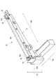
- FIG. 3 is an external perspective view of the droplet detection device 20.
- FIG. 4 is an external perspective view of the droplet detection device 20 with the cover 22 removed.
- the droplet detection device 20 includes an ink adsorption case 21 that receives and adsorbs the minute droplets 91 discharged from the nozzle 16a, and a cover attached to the ink adsorption case 21. 22 and a light emitting element 23 that irradiates detection light for detecting the minute droplet 91 in the direction of the arrow 10b intersecting the traveling direction of the minute droplet 91 indicated by the arrow 10d (for example, LED (Light Emitting Diode)).
- LED Light Emitting Diode
- a light receiving element 24 for example, PD (Photo Diode)
- PD Photo Diode
- the droplet detection device 20 is configured such that when the minute droplet 91 is ejected from the nozzle 16 a of the head 16, at least a part of the detection light emitted from the light emitting element 23 is blocked by the minute droplet 91. This is a device that detects a micro droplet 91 when the amount of light received at 24 becomes less than a specific amount than planned.
- the cover 22 has a pair of wall portions 22a and 22a arranged in parallel to each other with a space in the main scanning direction (arrow 10a direction).
- the opposing surfaces of the wall portions 22a and 22a are flat surfaces along the sub-scanning direction (arrow 10b direction), and the micro droplet 91 discharged from the nozzle 16a is interposed between the wall portions 22a and 22a. Is going to pass.
- the wall portion 22a may not be planar.
- the wall 22a may have a curved shape on a cross section cut by a plane orthogonal to the direction of the arrow 10b, that is, a curved surface.
- the wall portion 22a is planar, it is possible to suppress unevenness in sensitivity in the direction of the arrow 10c for detecting the minute droplet 91 in the droplet detection device 30.
- the width in the direction of the arrow 10a of the passage region of the micro droplet 91 between the pair of walls 22a is the width between the pair of walls 22a in the direction of the arrow 10a. Is limited by the narrowest part. Therefore, the pair of wall portions 22a is preferably planar.
- wall portions 22a and 22a are provided symmetrically across the optical path 20a of the detection light emitted from the light emitting element 23 toward the light receiving element 24.
- the wall portion is provided.
- Light diffused in the opposite direction of 22a, 22a (main scanning direction: arrow 10a direction) is reflected by the walls 22a, 22a, and the traveling direction of the reflected light is received in the sub-scanning direction (arrow 10b direction). It is changed to the element 24 side.
- the light diffused in the main scanning direction can reach the light receiving element 24 side while being repeatedly reflected by the walls 22a and 22a, and is sandwiched between the walls 22a and 22a in the optical path 20a of the detection light.
- a reduction in the amount of light due to the diffusion of the detection light can be suppressed by the light collection effect due to the reflection at the walls 22a and 22a.
- the amount of detection light received by the light receiving element 24 is larger than when the walls 22a and 22a are not provided, so that the microdroplet 91 to be described later is improved without improving the performance of the light receiving element 24. Detection sensitivity can be improved.
- the reachable distance (receivable distance) of the detection light is increased, so that the separation distance between the light emitting element 23 and the light receiving element 24 can be increased. In this case, it is possible to widen the range in the sub-scanning direction (arrow 10b direction) that can be used for the detection of the fine ink droplets.
- the length of the light receiving area where the light receiving element 24 can receive the detection light in the direction of the arrow 10a is equal to or longer than the interval 22b (see FIG. 7) between the pair of wall portions 22a and 22a in the direction of the arrow 10a. It is preferable that If the length of the light receiving area in the direction of the arrow 10a of the light receiving element 24 is equal to or greater than the interval 22b between the pair of wall portions 22a, 22a, the entire detection light in the direction of the arrow 10a passing between the pair of wall portions 22a, 22a Since the range can be used for detection, a wide detection range of the micro droplet 91 can be secured.
- the interval 22b between the pair of wall portions 22a and 22a in the direction of the arrow 10a is When at least a portion in the direction of the arrow 10b (sub-scanning direction) differs from another portion, and the interval 22b in the direction of the arrow 10a is not the same over the entire length in the direction of the arrow 10b, the arrow The interval 22b in the 10a direction may be equal to or greater than the interval of the shortest portion.
- the pair of wall portions 22a and 22a face each other in a parallel state. That is, the distance 22b between the pair of wall portions 22a and 22a in the facing direction (arrow 10a direction) is the same in the entire range in the arrow 10b direction.
- the pair of wall portions 22a may not face each other in a parallel state. For example, when both of the pair of wall portions 22a are planar, the pair of wall portions 22a do not face each other in a parallel state due to different extending directions of the pair of wall portions 22a. Also good.
- the pair of wall portions 22a are in a state in which at least one of the pair of wall portions 22a is curved on a cross section cut by a plane orthogonal to the direction of the arrow 10c, that is, in a state parallel to each other by being curved. It does not have to be opposite.
- the length 22c of the pair of wall portions 22a and 22a in the direction of the arrow 10b is equal to or larger than the width 16c in the direction of the arrow 10b of the row 16b of the nozzles 16a in the plurality of heads 16 as a whole.
- FIG. 5 is a view of a cross section obtained by cutting a partial region on the light emitting element 23 side of the droplet detection device 20 along a surface along the arrow 10b as seen from the direction of the arrow 10a.
- the light emitting element 23 when viewed from the arrow 10a direction side, the light emitting element 23 is provided such that the center of the light emitting element 23 in the direction of the arrow 10c coincides with the center of the slit 25a in the direction of the arrow 10c.
- the width 23b of the light emitting portion 23a of the element 23 in the arrow 10c direction (vertical direction) is wider than the width 25b of the slit 25a in the arrow 10c direction. Therefore, of the detection light emitted from the light emitting element 23, the region 22e (hereinafter referred to as “end part region”) sandwiched between the end portions 22d of the pair of wall portions 22a and 22a on the light emitting element 23 side through the slit 25a.
- the detection light emitted in (shown) becomes detection light having a width equal to the width 25b of the slit 25a in the direction of the arrow 10c. That is, the slit 25a limits the width of the detection light in the direction of the arrow 10c in the end region 22e.
- the width 25b of the slit 25a in the direction of the arrow 10c is set so that the amount of detection light received by the light receiving element 24 is greater than or equal to a certain amount.
- the detection light emitted from the light emitting element 23 is detected. It is set to an arbitrary width determined according to the light emission intensity.
- the light width limiting member 25 having the slit 25a is replaceable, and when the emission intensity of the detection light emitted from the light emitting element 23 is strong, the width 25b of the slit 25a in the direction of the arrow 10c is When the narrow light width limiting member 25 is employed and the light emission intensity is weak, the light width limiting member 25 having a wide width 25b of the slit 25a in the direction of the arrow 10c is employed, so that the amount of detection light received by the light receiving element 24 can be reduced.
- the light intensity can be adjusted to a certain level or more.
- FIG. 6 is a view of a cross section obtained by cutting a partial region on the light emitting element 23 side of the droplet detection device 20 along a surface along the arrow 10a as viewed from the direction of the arrow 10c.
- the light emitting element 23 is provided with the center of the light emitting element 23 in the direction of the arrow 10a aligned with the center of the slit 25a in the direction of the arrow 10a.
- the width 25c of the slit 25a in the direction of the arrow 10a is set to a width equal to or greater than the distance 22b between the pair of wall portions 22a and 22a in the direction of the arrow 10a.
- the width 23c is wider than the interval 22b between the pair of wall portions 22a and 22a in the direction of the arrow 10a.
- the detection light irradiated through the slit 25a and into the end region 22e of the pair of wall portions 22a and 22a has a width 25b in the direction of the arrow 10a of the slit 25a.
- the detection light has the same width as.
- FIG. 7 is a cross-sectional view of the pair of wall portions 22a and 22a of the droplet detection device 20 cut along a plane along the arrow 10a, as viewed from the light receiving element 24 side, and the light width is limited when viewed from the direction of the arrow 10b. It is a figure explaining the relationship between the magnitude
- the upper end 25d and the lower end 25e of the slit 25a extend linearly in the direction of the arrow 10a (left and right in the figure) and are positioned parallel to each other, and the width 25b of the slit 25a in the direction of the arrow 10c. Has the same width over the entire length in the direction of the arrow 10a.
- the light width limiting member 25 passes through the slit 25a among the detection light emitted from the light emitting element 23 by the regions 25f and 25f located on the upper side and the lower side with the slit 25a interposed therebetween, and the pair of wall portions 22a. , 22a defines the width of the detection light irradiated in the end region 22e in the direction of the arrow 10c.
- the pair of wall portions 22a and 22a have the same interval 22b in the direction of the arrow 10a in the entire range in the direction of the arrow 10c.
- the light emitting portion 23a of the light emitting element 23 is larger than the rectangular hole 20b formed by the pair of wall portions 22a and the slit 25a as shown in FIG. 7 when observed from the light receiving element 24 side.
- the width in the direction of the arrow 10a in the end region 22e is equal to the interval 22b in the entire range in the direction of the arrow 10c. Further, in the detection light emitted from the light emitting element 23, the width in the direction of the arrow 10c in the end region 22e is equal to the width 25b of the slit 25a in the direction of the arrow 10c in the entire range in the direction of the arrow 10a.
- the control unit of the inkjet printer 10 ejects ink toward the medium 90 based on the transmitted print data.
- the image is printed on the medium 90.
- the control unit changes the relative position of the head 16 with respect to the medium 90 in the main scanning direction (arrow 10a direction) and the sub-scanning direction (arrow 10b direction), while moving the ink from the head 16 toward the medium 90.
- a small droplet 91 (see FIG. 2) is discharged.
- control unit when changing the position in the main scanning direction indicated by the arrow 10a among the relative positions of the head 16 with respect to the medium 90, the control unit moves the carriage 15 along the guide rail 14 in the main scanning direction indicated by the arrow 10a. Move to.
- control unit when changing the position in the sub-scanning direction indicated by the arrow 10b among the relative positions of the head 16 with respect to the medium 90, the control unit causes the medium transport device to move the medium 90 in the sub-scanning direction indicated by the arrow 10b. .
- control unit of the ink jet printer 10 appropriately discharges the micro droplets 91 from the nozzles 16a of the head 16 at a specific time such as when a specific number of times of printing is completed or when a user gives an instruction. Perform a check to see if it can.
- control unit moves the carriage 15 along the guide rail 14 in the main scanning direction indicated by the arrow 10 a, so that the row 16 b of nozzles 16 a of the head 16 to be inspected and the droplet detection device 20.
- the region between the pair of wall portions 22a and 22a is opposed in the direction of the arrow 10c.
- control unit sequentially sets each of the nozzles 16a of the inspection target head 16 to be inspected, and irradiates the detection light from the light emitting element 23. Discharge.
- the micro droplet 91 is appropriately applied from the nozzle 16a to be inspected. It is determined whether or not ejection is possible. As described above, when the light amount of the detection light received by the light receiving element 24 is decreased by a certain degree while the micro droplet 91 is being ejected from the nozzle 16a to be inspected, the control unit detects the droplet detection device. 20, it is determined that the minute droplet 91 is detected, that is, the minute droplet 91 can be appropriately discharged from the nozzle 16 a to be inspected.
- control unit has positioned all of the plurality of minute droplets 91 continuously ejected in order to determine whether the nozzle 16a is clogged in the spot of the detection light received by the light receiving element 24.
- the presence or absence of nozzle clogging is determined based on the light shielding rate (light quantity) of the detection light received by the light receiving element 24. That is, when the light shielding rate (light quantity) of the detection light received by the light receiving element 24 is equal to or larger than a threshold value that is a predetermined light shielding rate, it is determined that the nozzle 16a is not clogged, and when it is less than the threshold value, the nozzle 16a is clogged. judge.
- the outer diameter of the light emitting element 23 indicated by a broken line in the drawing is larger than the interval 22b between the pair of wall portions 22a and 22a (see FIG. 7). Therefore, in the droplet detection device 20, the detection light emitted from the light emitting element 23 is emitted from the pair of wall portions 22a and 22a at the end region 22e sandwiched between the end portions 22d and 22d on the light emitting element 23 side.
- the wall portions 22a and 22a are irradiated with no gap over the entire length of the interval 22b in the direction of the arrow 10a. For this reason, no gap is formed between the wall portions 22a and 22a and the detection light in the direction of the arrow 10a. Therefore, it is possible to suppress the occurrence of a shadow between the pair of wall portions 22a and 22a due to the gap. .
- FIG. 8 is a view of a cross section of the pair of wall portions 22a and 22a of the droplet detecting device 30 according to the comparative example cut along a plane along the arrow 10a, as viewed from the light receiving element 24 side, and is a slit in the direction of the arrow 10a. It is a figure explaining the light width limiting member 25 whose width 25c of 25a is smaller than the space
- the droplet detection device 30 shown in FIG. 8 has a larger interval 22b between the pair of wall portions 22a and 22a.
- the width 25c of the slit 25a in the direction of the arrow 10a is smaller than the distance 22b between the pair of wall portions 22a and 22a in the direction of the arrow 10a. Therefore, the interval 22b between the pair of wall portions 22a and 22a is wider than the width of the detection light in the direction of the arrow 10a in the end region 22e.
- the detection light irradiated through the slit 25 a to the space 22 b between the wall portions 22 a and 22 a is incident on the light width limiting member 25 on both sides of the slit 25 a in the direction of the arrow 10 a.
- region (gap 30a, 30a) between slit 25a and wall part 22a, 22a will arise. That is, in the droplet detection device 30, in the end region 22e (see FIG. 6) between the pair of wall portions 22a and 22a (see FIG. 6), the wall portion 22a in the direction of the arrow 10a and the detection light in the entire range in the arrow 10c direction.
- a gap 30a is formed between the two.
- FIG. 9 is a diagram showing an example of a sensitivity map in the droplet detection device 30.
- the range indicated by hatching represents the shade generated due to the gap 30a in the optical path 20a (see FIG. 4) of the detection light, and the sensitivity is poor and the micro droplet 91 (see FIG. 2).
- This is a range that cannot be used for detection. That is, in the droplet detection device 30, a spot (shadow) of sensitivity of detection of the micro droplet 91 is generated in the range between the pair of wall portions 22 a and 22 a that is the detection range of the micro droplet 91. Then, when there is a shadow below the nozzle hole to be inspected, the minute droplet 91 that has passed through the shadow portion is detected by the light receiving element 24 even if it is normally ejected from the nozzle hole.
- the shaded range is a range that cannot be used to detect the minute droplet 91 (see FIG. 2). That is, in the droplet detection device 30, it is difficult to accurately detect the minute droplet 91.
- a spot of sensitivity of detection of the micro droplet 91 is generated in a range between the pair of walls 22a and 22a, which is a detection range of the micro droplet 91.
- the reason why the insensitive range does not occur symmetrically about the center line 30b in the direction of the arrow 10a is that the light emitting element 23, the light receiving element 24, and the light width limitation. For example, an error between a position at the time of assembling each of the member 25 and the light width limiting member 26 and the pair of wall portions 22a and 22a and a design position.
- the micro droplet 91 is discharged in the range 31 or 32 in which no shade with good sensitivity is generated.
- the control unit it is necessary to control the position of the carriage 15 in the direction of the arrow 10a by the control unit. Therefore, in order to detect the minute droplet 91, high-precision control by the control unit is necessary for positioning the carriage 15 in the direction of the arrow 10a, and for positioning the carriage 15 in the direction of the arrow 10a. I need time.
- FIG. 10 is a diagram showing an example of a sensitivity map in the droplet detection device 20.
- the droplet detection device 20 of FIG. 10 there is no range in which the sensitivity is poor and cannot be used for detection of the minute droplet 91 (see FIG. 2). That is, in the droplet detection device 20, there is no unevenness in detection sensitivity of the micro droplet 91 in the range between the pair of wall portions 22a that is the detection range of the micro droplet 91 (see FIG. 2). . In the situation shown in FIG. 10, even if any range in the range between the pair of walls 22a, 22a is used, the fine droplet 91 can be detected accurately and easily with good sensitivity. Compared to the situation shown, it is not necessary to control the position of the carriage 15 in the direction of the arrow 10a with high accuracy.
- the droplet detection device 20 can suppress the occurrence of shade in the range between the pair of wall portions 22a and 22a, even if it does not include a parallel light source that uses an expensive device such as a laser, the droplet detection device 20 It is accurate and easy to detect the minute droplets 91 with high accuracy by suppressing the occurrence of unevenness in detection sensitivity of the minute droplets 91 in the range between the pair of wall portions 22a and 22a, which is the detection range of the droplets 91. Can be done. Accordingly, the manufacturing cost of the droplet detection device 20 and the inkjet printer 10 including the droplet detection device 20 can be lower than that of the conventional droplet detection device and the conventional inkjet printer.
- the droplet detection device 20 Since the droplet detection device 20 is formed with the slit 25a that limits the width of the detection light in the end region 22e in the direction of the arrow 10c, the detection light emitted from the light emitting element 23 travels to the light receiving element 24 side. Diffusion in the direction of the arrow 10c can be suppressed. Therefore, the droplet detection device 20 receives the detection light emitted from the light emitting element 23 in the direction of the arrow 10c while traveling toward the light receiving element 24 and reflected by some member such as the head 16 and then received by the light receiving element 24. That can be suppressed. Therefore, the droplet detection device 20 can suppress the occurrence of uneven sensitivity of detection of the micro droplet 91. That is, the droplet detection device 20 can detect the minute droplet 91 with high accuracy.
- the droplet detection device 20 The width of the detection light in the direction of the arrow 10a in the end region 22e is equal to the interval 22b in the entire range in the direction of the arrow 10c, Since the width of the detection light in the direction of the arrow 10c in the end region 22e is equal to the width 25b of the slit 25a in the direction of the arrow 10c in the entire range in the direction of the arrow 10a, In the detection range of the micro droplet 91, the occurrence of unevenness in the amount of detection light in both the arrow 10a direction and the arrow 10c direction can be suppressed. Therefore, the droplet detection device 20 can suppress the occurrence of uneven sensitivity of detection of the micro droplet 91. That is, the droplet detection device 20 can detect the minute droplet 91 with high accuracy.
- the droplet detection device 20 has a configuration in which no gap is formed between the wall 22a and the detection light in the direction of the arrow 10a in the end region 22e in at least a part of the range in the direction of the arrow 10c.
- the width of the detection light in the direction of the arrow 10a in the end region 22e may not be equal to the interval 22b in the entire range in the direction of the arrow 10c.
- the droplet detection device 20 has a configuration in which no gap is formed between the wall 22a and the detection light in the direction of the arrow 10a in the end region 22e in at least a part of the range in the direction of the arrow 10c.
- the width of the detection light in the direction of the arrow 10c in the end region 22e may not be equal to the width 25b of the slit 25a in the direction of the arrow 10c in the entire range in the direction of the arrow 10a.
- the light emitting element 23 may be arranged so as to be biased in the direction opposite to the arrow 10d direction (upward in the drawing) with respect to the slit 25a.
- the width of the detection light in the direction of the arrow 10a in the end region 22e is partially different from the interval 22b in the direction of the arrow 10c (interval 22b).
- the width of the detection light in the direction of the arrow 10c in the end region 22e is also different from the width 25b of the slit 25a in the direction of the arrow 10c in the entire range in the direction of the arrow 10a.
- the droplet detection device 20 has a configuration in which no gap is formed between the wall 22a and the detection light in the direction of the arrow 10a in the end region 22e in at least a part of the range in the direction of the arrow 10c. Even if the width 25b between the two portions 25f in the direction of the arrow 10c in the direction of the arrow 10c is equal in the entire range in the direction of the arrow 10a, the width 25b of the two portions 25f that limit the width of the detection light in the end region 22e in the direction of the arrow 10c of the slit 25a good.
- the shapes of the upper end 25d and the lower end 25e of the slit 25a may be bent.
- the width of the detection light in the direction of the arrow 10a in the end region 22e is partially different from the interval 22b in the direction of the arrow 10c.
- the ink jet printer 10 is within the detection range of the micro droplet 91 of the droplet detection device 20 and can suppress the occurrence of spots of sensitivity of detection of the micro droplet 91, and the detection light diffuses and the light amount is lost. Therefore, the detection range of the micro droplet 91 by the droplet detection device 20 in the extending direction indicated by the arrow 10b of the row 16b of the nozzle 16a of the head 16 can be extended and extended. Accordingly, the ink jet printer 10 has the nozzle 16a of at least two heads 16 out of the plurality of heads 16 with respect to the droplet detection device 20 even though the positions of the rows 16b in the direction of the arrow 10b are shifted from each other. Thus, the minute droplets 91 can be detected for all the nozzles 16a of the plurality of heads 16 without moving the head 16 in the direction of the arrow 10b.
- the inkjet printer 10 may be arranged such that the positions of the plurality of heads 16 in the direction of at least two arrows 10b are shifted from each other by an arrangement other than the staggered arrangement. Further, in the inkjet printer 10, the positions of all the heads 16 in the direction of the arrow 10b may be equal.
- Inkjet printer 10a Arrow (an arrow indicating the facing direction of a pair of wall portions) 10b Arrow (an arrow indicating the light emitting direction of the detection light, an arrow indicating the extending direction of the optical path) 10c arrow (an arrow indicating an orthogonal direction to both the opposing direction of the pair of wall portions and the extending direction of the optical path) 10d arrow (arrow indicating the direction of travel of microdroplet) 16 head 16a nozzle 16b row 16c width (width of nozzle row in the whole of a plurality of heads) 20 Droplet detection apparatus 20a Optical path 22a Wall part 22b Space
Landscapes
- Engineering & Computer Science (AREA)
- Quality & Reliability (AREA)
- Ink Jet (AREA)
Abstract
【課題】従来より製造コストを抑えることができる液滴検出装置およびインクジェットプリンターを提供する。 【解決手段】液滴検出装置は、インクジェットプリンターのヘッドのノズルから吐出される微小液滴による少なくとも一部の遮りを検出するための検出光を微小液滴の進行方向と交差する矢印10b方向に発する発光素子23と、検出光を受ける受光素子と、互いに対向して配置されていて間に微小液滴を通過させる一対の壁部22aと、を備え、一対の壁部22aは、発光素子23から受光素子までの検出光の光路の一部を間に形成するとともに、検出光の少なくとも一部を反射して受光素子に到達させ、検出光は、一対の壁部22aの発光素子23側の端部22dで挟まれた領域22eにおいて、矢印10a方向の幅が一対の壁部22aの矢印10a方向の間隔22bと等しいことを特徴とする。
Description
本発明は、インクジェットプリンターのヘッドのノズルから吐出される微小液滴を検出する液滴検出装置、およびこの液滴検出装置を備えるインクジェットプリンターに関する。
従来、インクジェットプリンターのヘッドのノズルから吐出される微小液滴を検出する液滴検出装置として、平行化光源を備えているものが知られている(例えば、特許文献1参照。)。
しかしながら、平行化光源は、レーザーなどの高価な装置を使用する必要がある。したがって、従来の液滴検出装置は、製造コストが高いという問題がある。
そこで、本発明は、従来より製造コストを抑えることができる液滴検出装置およびインクジェットプリンターを提供することを目的とする。
本発明は、インクジェットプリンターのヘッドのノズルから吐出される液滴(微小液滴)を、当該液滴による検出光の遮りの有無に基づいて検出する液滴検出装置であって、
前記ノズルから吐出された前記液滴の進行方向と交差する方向に、前記検出光を照射する発光素子と、
前記発光素子から照射された前記検出光を受光する受光素子と、
前記液滴が通過する間隔をあけて、互いに対向して配置された一対の壁部と、を備え、
前記一対の壁部は、前記発光素子から前記受光素子までの前記検出光の光路の少なくとも一部が、前記一対の壁部の間を通過するように、前記光路に沿って設けられており、
前記光路における前記一対の壁部の間の領域では、前記検出光の少なくとも一部が、前記一対の壁部の互いの対向面で反射しながら、前記受光素子側に誘導されるようにしたことを特徴とする。
前記ノズルから吐出された前記液滴の進行方向と交差する方向に、前記検出光を照射する発光素子と、
前記発光素子から照射された前記検出光を受光する受光素子と、
前記液滴が通過する間隔をあけて、互いに対向して配置された一対の壁部と、を備え、
前記一対の壁部は、前記発光素子から前記受光素子までの前記検出光の光路の少なくとも一部が、前記一対の壁部の間を通過するように、前記光路に沿って設けられており、
前記光路における前記一対の壁部の間の領域では、前記検出光の少なくとも一部が、前記一対の壁部の互いの対向面で反射しながら、前記受光素子側に誘導されるようにしたことを特徴とする。
この構成により、検出光の光路における一対の壁部が設けられた領域では、検出光の少なくとも一部が、一対の壁部の互いの対向面で反射しながら、受光素子側に誘導されるので、受光素子で受光する検出光の光量を確保することができる。
これにより、レーザーなどの高価な装置を使用せずに、インクジェットプリンターのヘッドのノズルから吐出される液滴を検出できるので、従来よりも製造コストを抑えた液滴検出装置の提供が可能になる。
そして、この液滴検出装置を備えたインクジェットプリンターもまた、従来よりも安価に提供することができる。
これにより、レーザーなどの高価な装置を使用せずに、インクジェットプリンターのヘッドのノズルから吐出される液滴を検出できるので、従来よりも製造コストを抑えた液滴検出装置の提供が可能になる。
そして、この液滴検出装置を備えたインクジェットプリンターもまた、従来よりも安価に提供することができる。
また、本発明の液滴検出装置の前記一対の壁部は、当該一対の壁部の対向方向と前記検出光の光路に沿う方向とに直交する直交方向に、それぞれ所定高さを有しており、
前記発光素子から照射された検出光の前記対向方向の幅は、前記直交方向の少なくとも一部の範囲で、前記一対の壁部の前記対向方向の前記間隔と等しいことが好ましい。
前記発光素子から照射された検出光の前記対向方向の幅は、前記直交方向の少なくとも一部の範囲で、前記一対の壁部の前記対向方向の前記間隔と等しいことが好ましい。
この構成により、本発明の液滴検出装置では、一対の壁部の発光素子側の端部で挟まれた領域において、一対の壁部の対向方向と、一対の壁部の間における光路に沿う方向との両方に対する直交方向の少なくとも一部の範囲で、一対の壁部の対向方向において壁部と、検出光との間に隙間を形成しないので、隙間が原因となる陰が一対の壁部の間の範囲に発生することを抑えることができる。
そのため、本発明の液滴検出装置は、レーザーなどの高価な装置を使用する平行化光源を備えなくても、微小液滴の検出範囲である一対の壁部の間の範囲における微小液滴の検出の感度の斑の発生を抑え、微小液滴を高精度に検出することができる。したがって、本発明の液滴検出装置は、従来より製造コストを抑えることができる。
そのため、本発明の液滴検出装置は、レーザーなどの高価な装置を使用する平行化光源を備えなくても、微小液滴の検出範囲である一対の壁部の間の範囲における微小液滴の検出の感度の斑の発生を抑え、微小液滴を高精度に検出することができる。したがって、本発明の液滴検出装置は、従来より製造コストを抑えることができる。
また、本発明の液滴検出装置の前記一対の壁部では、前記発光素子側の端部側に、前記検出光の前記直交方向の幅を制限するスリットが形成されていることが好ましい。
この構成により、本発明の液滴検出装置は、発光素子から発せられた検出光が受光素子側に進みながら直交方向に拡散することを抑えることができるので、発光素子から発せられた検出光が受光素子側に進みながら直交方向に拡散して何らかの部材に反射した後、受光素子によって受けられることを抑えることができる。
したがって、本発明の液滴検出装置は、検出光の拡散による光量のロスを抑えることで、微小液滴の検出を行う範囲を、均一な光量の検出光で満たすことができるので、微小液滴の検出の感度の斑の発生を抑えることができる。
すなわち、本発明の液滴検出装置は、微小液滴を高精度に検出できる。
したがって、本発明の液滴検出装置は、検出光の拡散による光量のロスを抑えることで、微小液滴の検出を行う範囲を、均一な光量の検出光で満たすことができるので、微小液滴の検出の感度の斑の発生を抑えることができる。
すなわち、本発明の液滴検出装置は、微小液滴を高精度に検出できる。
また、本発明の液滴検出装置において、前記スリットの前記直交方向における一方の端縁と他方の端縁は、それぞれ前記対向方向に直線状に延びると共に互いに平行に設けられており、
前記光路における前記一対の壁部の間の領域では、
前記検出光の前記対向方向の幅が、前記直交方向の全範囲で、前記一対の壁部の間の前記間隔と同じであり、
前記検出光の前記直交方向の幅が、前記対向方向の全範囲で、前記スリットの前記直交方向の幅と同じであることが好ましい。
前記光路における前記一対の壁部の間の領域では、
前記検出光の前記対向方向の幅が、前記直交方向の全範囲で、前記一対の壁部の間の前記間隔と同じであり、
前記検出光の前記直交方向の幅が、前記対向方向の全範囲で、前記スリットの前記直交方向の幅と同じであることが好ましい。
この構成により、本発明の液滴検出装置は、微小液滴の検出範囲において、一対の壁部の対向方向と、直交方向との両方における検出光の光量の斑の発生を抑えることができるので、微小液滴の検出の感度の斑の発生を抑えることができる。すなわち、本発明の液滴検出装置は、微小液滴を高精度に検出することができるので、微小液滴の検出を正確かつ簡単に行うことができる。
また、本発明の液滴検出装置において、前記受光素子が前記検出光を受光可能である受光可能領域の前記対向方向における長さは、前記対向方向における前記一対の壁部の間隔以上であっても良い。
この構成により、本発明の液滴検出装置は、一対の壁部の対向方向において、一対の壁部の間の検出光の全領域を検出することができる。すなわち、本発明の液滴検出装置は、微小液滴の検出範囲を広く確保しつつ全範囲で微小液滴の検出をすることができる。
本発明の液滴検出装置は、前記受光素子で受光した検出光の光量が、所定の光量よりも所定量以上低下した場合に、液滴(微小液滴)による検出光の遮りがあると判定する判定手段と、
前記ノズル列を構成する複数のノズルの各々から、前記液滴(微小液滴)を順番に吐出させると共に、前記判定手段による判定結果に基づいて、前記複数のノズル各々の詰まりの有無を判定する異常判定手段と、を有することが好ましい。
前記ノズル列を構成する複数のノズルの各々から、前記液滴(微小液滴)を順番に吐出させると共に、前記判定手段による判定結果に基づいて、前記複数のノズル各々の詰まりの有無を判定する異常判定手段と、を有することが好ましい。
このように構成すると、複数のノズル各々の詰まりの有無を適切に判定することができる。
本発明のインクジェットプリンターは、前記した液滴検出装置と、前記液滴(微小液滴)を吐出するノズルが前記光路に沿う方向に直線状に並んだノズル列を有する複数のヘッドと、を備え、
前記複数のヘッドは、前記光路に沿う方向における一方側に位置するヘッドと、他方側に位置するヘッドとから構成されており、
前記一対の壁部の前記光路に沿う方向の長さが、前記一方側に位置するヘッドの前記ノズル列と前記他方側に位置するヘッドの前記ノズル列とが位置する範囲の前記光路に沿う方向の長さよりも長いことを特徴とする。
前記複数のヘッドは、前記光路に沿う方向における一方側に位置するヘッドと、他方側に位置するヘッドとから構成されており、
前記一対の壁部の前記光路に沿う方向の長さが、前記一方側に位置するヘッドの前記ノズル列と前記他方側に位置するヘッドの前記ノズル列とが位置する範囲の前記光路に沿う方向の長さよりも長いことを特徴とする。
この構成により、本発明のインクジェットプリンターは、従来より製造コストを抑えることができる液滴検出装置を備えているので、従来より製造コストを抑えることができる。
また、本発明のインクジェットプリンターは、液滴検出装置の微小液滴の検出範囲における、微小液滴の検出の感度の斑の発生を抑えることができると共に、検出光が拡散して光量をロスすることが抑えられるので、ヘッドのノズル列が延びる方向における液滴検出装置による微小液滴の検出範囲を延長拡張することができる。
したがって、本発明のインクジェットプリンターは、ノズル列が延びる方向に液滴検出装置に対してヘッドを移動させなくても、複数のヘッドの全てのノズルに対して微小液滴を検出することができる。
また、本発明のインクジェットプリンターは、液滴検出装置の微小液滴の検出範囲における、微小液滴の検出の感度の斑の発生を抑えることができると共に、検出光が拡散して光量をロスすることが抑えられるので、ヘッドのノズル列が延びる方向における液滴検出装置による微小液滴の検出範囲を延長拡張することができる。
したがって、本発明のインクジェットプリンターは、ノズル列が延びる方向に液滴検出装置に対してヘッドを移動させなくても、複数のヘッドの全てのノズルに対して微小液滴を検出することができる。
本発明の液滴検出装置およびインクジェットプリンターは、従来より製造コストを抑えることができる。
以下、本発明の一実施の形態について、図面を用いて説明する。
まず、本実施の形態に係るインクジェットプリンターの構成について説明する。
図1は、本実施の形態に係るインクジェットプリンター10の外観斜視図である。
図1に示すように、インクジェットプリンター10は、床に設置される脚部11と、脚部11に支持されていて矢印10a方向(主走査方向)に延在している本体12と、を備えている。
本体12は、矢印10a方向に直交する矢印10b方向(副走査方向)に媒体90を搬送するための図示していない媒体搬送装置と、矢印10a方向に延びるガイドレール14と、ガイドレール14に支持されていると共に、矢印10a方向(主走査方向)に移動可能に設けられたキャリッジ15と、キャリッジ15に搭載されていて媒体90に向けてインクを吐出する複数のヘッド16と、ヘッド16から吐出されるインクの微小液滴を検出する液滴検出装置20と、ガイドレール14、キャリッジ15、ヘッド16および液滴検出装置20を覆うケース17と、インクジェットプリンター10全体の動作を制御する図示していない制御部と、を備えている。
複数のヘッド16は、スタガ配列されている。したがって、キャリッジ15において主走査方向(矢印10a方向)に並んで配置された複数のヘッド16は、主走査方向で隣接するヘッド16、16同士が、副走査方向(矢印10b方向)に位置をずらして配置されている。
液滴検出装置20は、本体12の内部において、本体12の矢印10a方向における一端側の媒体90が搬送されない位置、すなわち、ヘッド16の退避位置に配置されている。
制御部は、例えば、CPU(Central Processing Unit)と、プログラムおよび各種のデータを予め記憶しているROM(Read Only Memory)と、CPUの作業領域として用いられるRAM(Random Access Memory)と、を備えている。
CPUは、ROMに記憶されているプログラムを実行するようになっている。
CPUは、ROMに記憶されているプログラムを実行するようになっている。
図2は、図1に示すA-A矢視断面図の一部である。
図2に示すように、ヘッド16は、インクの微小液滴91を吐出する複数のノズル16aが所定間隔で並んだノズル列16bを、媒体90(図1参照)との対向面に備えており、ヘッド16においてノズル列16bは、矢印10b方向(副走査方向)に沿って設けられている。
ノズル16aの各々は、主走査方向(矢印10a方向:図1参照)と副走査方向(矢印10b方向)の両方に直交する上下方向(矢印10c方向:直交方向)において、矢印10dで示す側(下側)に位置する媒体90に向けてインクを吐出するように設けられている。
なお、図2では、複数のヘッドを備えるキャリッジ15の主走査方向(矢印10a方向)の位置が、キャリッジ15が備える複数のヘッド16のうち1つのヘッド16の下側に、液滴検出装置20が配置される位置である場合を示している。
ノズル16aの各々は、主走査方向(矢印10a方向:図1参照)と副走査方向(矢印10b方向)の両方に直交する上下方向(矢印10c方向:直交方向)において、矢印10dで示す側(下側)に位置する媒体90に向けてインクを吐出するように設けられている。
なお、図2では、複数のヘッドを備えるキャリッジ15の主走査方向(矢印10a方向)の位置が、キャリッジ15が備える複数のヘッド16のうち1つのヘッド16の下側に、液滴検出装置20が配置される位置である場合を示している。
図3は、液滴検出装置20の外観斜視図である。
図4は、カバー22が取り外された状態での液滴検出装置20の外観斜視図である。
図4は、カバー22が取り外された状態での液滴検出装置20の外観斜視図である。
図2~図4に示すように、液滴検出装置20は、ノズル16aから吐出された微小液滴91を受けて吸着するインク吸着用ケース21と、このインク吸着用ケース21に取り付けられたカバー22と、微小液滴91を検出するための検出光を、矢印10dで示す微小液滴91の進行方向と交差する矢印10b方向に照射する発光素子23(例えば、LED(Light Emitting Diode)など)と、発光素子23から照射された検出光を受光する受光素子24(例えばPD(Photo Diode)など)と、発光素子23から照射された検出光の幅を制限するスリット25aが形成された光幅制限部材25と、受光素子24によって受光する検出光の幅を制限するスリット26aが形成された光幅制限部材26と、を備えている。
液滴検出装置20は、ヘッド16のノズル16aから微小液滴91が吐出された場合に、発光素子23から照射された検出光の少なくとも一部が微小液滴91に遮られることによって、受光素子24で受光する光量が予定より特定の量以上少なくなったときに、微小液滴91を検出する装置である。
カバー22は、主走査方向(矢印10a方向)に間隔を空けて互いに平行に配置された一対の壁部22a、22aを有している。
これら壁部22a、22aの互いの対向面は、副走査方向(矢印10b方向)に沿う平坦面となっており、これら壁部22a、22aの間を、ノズル16aから吐出された微小液滴91が通過するようになっている。
これら壁部22a、22aの互いの対向面は、副走査方向(矢印10b方向)に沿う平坦面となっており、これら壁部22a、22aの間を、ノズル16aから吐出された微小液滴91が通過するようになっている。
なお、壁部22aは、平面状でなくても良い。
例えば、壁部22aは、矢印10b方向に直交する平面で切断した断面上で曲線である状態、すなわち、曲面状であっても良い。
しかしながら、壁部22aは、平面状である場合、液滴検出装置30における微小液滴91の検出の矢印10c方向の感度の斑を抑制することができる。
また、壁部22aが曲面状である場合には、一対の壁部22aの間の微小液滴91の通過領域の矢印10a方向における幅は、矢印10a方向において一対の壁部22aの間の幅が最も狭くなっている部分によって制限されてしまう。
したがって、一対の壁部22aは、平面状であることが好ましい。
例えば、壁部22aは、矢印10b方向に直交する平面で切断した断面上で曲線である状態、すなわち、曲面状であっても良い。
しかしながら、壁部22aは、平面状である場合、液滴検出装置30における微小液滴91の検出の矢印10c方向の感度の斑を抑制することができる。
また、壁部22aが曲面状である場合には、一対の壁部22aの間の微小液滴91の通過領域の矢印10a方向における幅は、矢印10a方向において一対の壁部22aの間の幅が最も狭くなっている部分によって制限されてしまう。
したがって、一対の壁部22aは、平面状であることが好ましい。
これら壁部22a、22aは、発光素子23から受光素子24に向けて照射された検出光の光路20aを挟んで対称に設けられており、発光素子23から照射された検出光のうち、壁部22a、22aの対向方向(主走査方向:矢印10a方向)に拡散した光が、壁部22a、22aにより反射されて、反射された光の進行方向が、副走査方向(矢印10b方向)における受光素子24側に変更されるようになっている。
そのため、主走査方向に拡散した光は、壁部22a、22aで反射を繰り返しながら受光素子24側まで到達できるようになっており、検出光の光路20aのうちの壁部22a、22aで挟まれた領域では、壁部22a、22aでの反射による集光効果によって、検出光の拡散による光量の低下を抑制できるようになっている。
これにより、受光素子24で受光される検出光の光量が、壁部22a、22aが設けられてない場合よりも多くなるので、受光素子24の性能を向上させることなく、後記する微小液滴91の検出感度を向上させることができる。
また、検出光の光量の低下が抑制されると、検出光の到達可能距離(受光可能距離)が長くなるので、発光素子23と受光素子24との離間距離を長くすることが可能になる。この場合には、インクの微小液滴の検出に用いることが可能な副走査方向(矢印10b方向)の範囲を広くとることができる。
また、受光素子24が検出光を受光可能である受光可能領域の矢印10a方向(主走査方向)の長さは、矢印10a方向における一対の壁部22a、22aの間隔22b(図7参照)以上であることが好ましい。
受光素子24の矢印10a方向の受光可能領域の長さを、一対の壁部22a、22aの間隔22b以上とすると、一対の壁部22a、22aの間を通過する検出光の矢印10a方向の全範囲を検出に用いることができるので、微小液滴91の検出範囲を広く確保することができる。
受光素子24の矢印10a方向の受光可能領域の長さを、一対の壁部22a、22aの間隔22b以上とすると、一対の壁部22a、22aの間を通過する検出光の矢印10a方向の全範囲を検出に用いることができるので、微小液滴91の検出範囲を広く確保することができる。
なお、矢印10a方向における受光素子24による受光可能領域の長さを、一対の壁部22a、22aの間隔22b以上とする場合に、矢印10a方向における一対の壁部22a、22aの間隔22bが、矢印10b方向(副走査方向)における少なくとも一部の箇所と他の箇所との間で異なっており、矢印10a方向の間隔22bが、矢印10b方向の全長に亘って同じになっていないときには、矢印10a方向の間隔22bが最も短くなっている箇所の間隔以上であれば良い。
一対の壁部22a、22aは、互いに平行な状態で対向している。すなわち、一対の壁部22a、22aの対向方向(矢印10a方向)の間隔22bは、矢印10b方向における全範囲で同一である。
なお、一対の壁部22aは、互いに平行な状態で対向していなくても良い。例えば、一対の壁部22aは、一対の壁部22aの両方が平面状である場合に、一対の壁部22aのそれぞれの延在方向が異なることによって、互いに平行な状態で対向していなくても良い。
また、一対の壁部22aは、一対の壁部22aの少なくとも一方が矢印10c方向に直交する平面で切断した断面上で曲線である状態、すなわち、曲面状であることによって、互いに平行な状態で対向していなくても良い。
なお、一対の壁部22aは、互いに平行な状態で対向していなくても良い。例えば、一対の壁部22aは、一対の壁部22aの両方が平面状である場合に、一対の壁部22aのそれぞれの延在方向が異なることによって、互いに平行な状態で対向していなくても良い。
また、一対の壁部22aは、一対の壁部22aの少なくとも一方が矢印10c方向に直交する平面で切断した断面上で曲線である状態、すなわち、曲面状であることによって、互いに平行な状態で対向していなくても良い。
図2に示すように、矢印10b方向における一対の壁部22a、22aの長さ22cは、複数のヘッド16の全体におけるノズル16aの列16bの矢印10b方向における幅16c以上である。
図5は、液滴検出装置20の発光素子23側の一部の領域を、矢印10bに沿う面で切断した断面を、矢印10a方向側から見た図である。
図5に示すように、矢印10a方向側から見て、発光素子23は、当該発光素子23の矢印10c方向の中心を、スリット25aの矢印10c方向の中心と一致させて設けられており、発光素子23の発光部分23aの矢印10c方向(上下方向)の幅23bは、矢印10c方向におけるスリット25aの幅25bより広くなっている。
そのため、発光素子23から照射された検出光のうち、スリット25aを通って、一対の壁部22a、22aの発光素子23側の端部22dで挟まれた領域22e(以下「端部領域」とも標記する)内に照射される検出光は、スリット25aの矢印10c方向の幅25bと等しい幅の検出光となるようになっている。
すなわち、スリット25aは、端部領域22eでの矢印10c方向における検出光の幅を制限するものである。
そのため、発光素子23から照射された検出光のうち、スリット25aを通って、一対の壁部22a、22aの発光素子23側の端部22dで挟まれた領域22e(以下「端部領域」とも標記する)内に照射される検出光は、スリット25aの矢印10c方向の幅25bと等しい幅の検出光となるようになっている。
すなわち、スリット25aは、端部領域22eでの矢印10c方向における検出光の幅を制限するものである。
なお、矢印10c方向におけるスリット25aの幅25bは、受光素子24が受光する検出光の光量が一定以上の光量になるように設定されており、実施の形態では、発光素子23から照射される検出光の発光強度に応じて決まる任意の幅に設定されている。
実施の形態では、スリット25aを有する光幅制限部材25が交換可能となっており、発光素子23から照射される検出光の発光強度が強い場合には、矢印10c方向のスリット25aの幅25bが狭い光幅制限部材25を採用し、発光強度が弱い場合には矢印10c方向のスリット25aの幅25bが広い光幅制限部材25を採用することで、受光素子24で受光する検出光の光量が一定以上の光量になるように調整できるようになっている。
実施の形態では、スリット25aを有する光幅制限部材25が交換可能となっており、発光素子23から照射される検出光の発光強度が強い場合には、矢印10c方向のスリット25aの幅25bが狭い光幅制限部材25を採用し、発光強度が弱い場合には矢印10c方向のスリット25aの幅25bが広い光幅制限部材25を採用することで、受光素子24で受光する検出光の光量が一定以上の光量になるように調整できるようになっている。
図6は、液滴検出装置20の発光素子23側の一部の領域を、矢印10aに沿う面で切断した断面を、矢印10c方向側から見た図である。
図6に示すように、矢印10c方向側から見て、発光素子23は、当該発光素子23の矢印10a方向の中心を、スリット25aの矢印10a方向の中心と一致させて設けられている。
矢印10a方向におけるスリット25aの幅25cは、矢印10a方向における一対の壁部22a、22aの間隔22b以上の幅に設定されており、発光素子23の発光部分23aの矢印10a方向(水平方向)の幅23cは、矢印10a方向における一対の壁部22a、22aの間隔22bより広くなっている。
矢印10a方向におけるスリット25aの幅25cは、矢印10a方向における一対の壁部22a、22aの間隔22b以上の幅に設定されており、発光素子23の発光部分23aの矢印10a方向(水平方向)の幅23cは、矢印10a方向における一対の壁部22a、22aの間隔22bより広くなっている。
そのため、発光素子23から照射された検出光のうち、スリット25aを通って、一対の壁部22a、22aの端部領域22e内に照射される検出光は、スリット25aの矢印10a方向の幅25bと等しい幅の検出光となるようになっている。
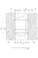
図7は、液滴検出装置20の一対の壁部22a、22aを、矢印10aに沿う面で切断した断面を受光素子24側から見た図であって、矢印10b方向から見て光幅制限部材25のスリット25aの大きさと、図中破線で示す発光素子23の外径との関係を説明する図である。
図7に示すように、スリット25aの上端25dおよび下端25eは、矢印10a方向(図中、左右方向)に直線状に延びると共に互いに平行に位置しており、スリット25aの矢印10c方向の幅25bは、矢印10a方向の全長に亘って同じ幅となっている。
そのため、光幅制限部材25は、スリット25aを挟んで上側と下側に位置する領域25f、25fにより、発光素子23から照射された検出光のうち、スリット25aを通って、一対の壁部22a、22aの端部領域22e内に照射される検出光の矢印10c方向の幅を規定している。
さらに、前記したように、一対の壁部22a、22aは、矢印10a方向における間隔22bが矢印10c方向における全範囲において等しい。
そして、発光素子23の発光部分23aは、受光素子24側から観察した場合に、図7に示すように、一対の壁部22aおよびスリット25aで形成される長方形の穴20bより大きい。
したがって、発光素子23から発せられた検出光は、端部領域22eにおける矢印10a方向での幅が矢印10c方向における全範囲において間隔22bと等しい。
また、発光素子23から発せられた検出光は、端部領域22eにおける矢印10c方向での幅が矢印10a方向における全範囲において矢印10c方向におけるスリット25aの幅25bと等しい。
また、発光素子23から発せられた検出光は、端部領域22eにおける矢印10c方向での幅が矢印10a方向における全範囲において矢印10c方向におけるスリット25aの幅25bと等しい。
次に、インクジェットプリンター10の動作について説明する。
インクジェットプリンター10の制御部は、図示していないPC(Personal Computer)などのコンピューターから印刷データが送信されてくると、送信されてきた印刷データに基づいて、媒体90に向けてインクを吐出して、媒体90上に画像を印刷する。
具体的には、制御部は、媒体90に対するヘッド16の相対位置を、主走査方向(矢印10a方向)と副走査方向(矢印10b方向)に変更しつつ、ヘッド16から媒体90に向けてインクの微小液滴91(図2参照)を吐出させる。
ここで、制御部は、媒体90に対するヘッド16の相対位置のうち、矢印10aで示す主走査方向における位置を変更する場合には、ガイドレール14に沿ってキャリッジ15を矢印10aで示す主走査方向に移動させる。
また、制御部は、媒体90に対するヘッド16の相対位置のうち、矢印10bで示す副走査方向における位置を変更する場合には、媒体搬送装置に媒体90を矢印10bで示す副走査方向に移動させる。
具体的には、制御部は、媒体90に対するヘッド16の相対位置を、主走査方向(矢印10a方向)と副走査方向(矢印10b方向)に変更しつつ、ヘッド16から媒体90に向けてインクの微小液滴91(図2参照)を吐出させる。
ここで、制御部は、媒体90に対するヘッド16の相対位置のうち、矢印10aで示す主走査方向における位置を変更する場合には、ガイドレール14に沿ってキャリッジ15を矢印10aで示す主走査方向に移動させる。
また、制御部は、媒体90に対するヘッド16の相対位置のうち、矢印10bで示す副走査方向における位置を変更する場合には、媒体搬送装置に媒体90を矢印10bで示す副走査方向に移動させる。
そして、インクジェットプリンター10の制御部は、特定の回数の印刷が終了した時点や、利用者から指示された時点など、特定の時点で、ヘッド16のノズル16aから適切に微小液滴91を吐出することができるか否かの検査を実行する。
具体的には、制御部は、ガイドレール14に沿ってキャリッジ15を矢印10aで示す主走査方向に移動させることによって、検査対象のヘッド16のノズル16aの列16bと、液滴検出装置20の一対の壁部22a、22aの間の領域とを、矢印10c方向で対向させる。
次いで、制御部は、検査対象のヘッド16のノズル16aの1つずつを順番に検査対象にし、発光素子23から検出光を照射させている状態で、検査対象のノズル16aから微小液滴91を吐出させる。
次いで、制御部は、検査対象のヘッド16のノズル16aの1つずつを順番に検査対象にし、発光素子23から検出光を照射させている状態で、検査対象のノズル16aから微小液滴91を吐出させる。
そして、検査対象のノズル16aから微小液滴91を吐出させている間に受光素子24で受光した検出光の光量の変化を測定することによって、検査対象のノズル16aから適切に微小液滴91を吐出することができているか否かを判定する。
このように、制御部は、検査対象のノズル16aから微小液滴91を吐出させている間に、受光素子24によって受けた検出光の光量が特定の程度以上減少した場合に、液滴検出装置20によって微小液滴91を検出した、すなわち、検査対象のノズル16aから適切に微小液滴91を吐出することができていると判定する。
具体的には、制御部は、受光素子24が受光する検出光のスポット内に、ノズル16aの詰まりの有無を判定するために連続して吐出された複数の微小液滴91を全て位置させたときの受光素子24が受光した検出光の遮光率(光量)によりノズル詰まりの有無を判定する。つまり、受光素子24が受光した検出光の遮光率(光量)が所定の遮光率である閾値以上の場合、ノズル16aは詰まりが無いと判定し、閾値未満の場合にノズル16aは詰まりがあると判定する。
このように、制御部は、検査対象のノズル16aから微小液滴91を吐出させている間に、受光素子24によって受けた検出光の光量が特定の程度以上減少した場合に、液滴検出装置20によって微小液滴91を検出した、すなわち、検査対象のノズル16aから適切に微小液滴91を吐出することができていると判定する。
具体的には、制御部は、受光素子24が受光する検出光のスポット内に、ノズル16aの詰まりの有無を判定するために連続して吐出された複数の微小液滴91を全て位置させたときの受光素子24が受光した検出光の遮光率(光量)によりノズル詰まりの有無を判定する。つまり、受光素子24が受光した検出光の遮光率(光量)が所定の遮光率である閾値以上の場合、ノズル16aは詰まりが無いと判定し、閾値未満の場合にノズル16aは詰まりがあると判定する。
前記したように、図中破線で示す発光素子23の外径が、一対の壁部22a、22aの間の間隔22bよりも大きくなっている(図7参照)。
そのため、液滴検出装置20では、一対の壁部22a、22aの発光素子23側の端部22d、22dで挟まれた端部領域22eにおいて、発光素子23から照射された検出光が、一対の壁部の22a、22aの矢印10a方向の間隔22bの全長に亘って隙間なく照射されるようになっている。
そのため、矢印10a方向で、壁部22a、22aと検出光との間に隙間が形成されないので、隙間が原因となる陰が一対の壁部22a、22aの間に発生することを抑えることができる。
そのため、液滴検出装置20では、一対の壁部22a、22aの発光素子23側の端部22d、22dで挟まれた端部領域22eにおいて、発光素子23から照射された検出光が、一対の壁部の22a、22aの矢印10a方向の間隔22bの全長に亘って隙間なく照射されるようになっている。
そのため、矢印10a方向で、壁部22a、22aと検出光との間に隙間が形成されないので、隙間が原因となる陰が一対の壁部22a、22aの間に発生することを抑えることができる。
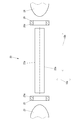
図8は、比較例にかかる液滴検出装置30の一対の壁部22a、22aを、矢印10aに沿う面で切断した断面を受光素子24側から見た図であって、矢印10a方向のスリット25aの幅25cが、一対の壁部22a、22aの間隔22bよりも小さい光幅制限部材25を説明する図である。
図8に示す液滴検出装置30は、図7に示す液滴検出装置20と比較して、一対の壁部22a、22aの間隔22bが広くなっている。
具体的には、液滴検出装置30において、矢印10a方向におけるスリット25aの幅25cは、矢印10a方向における一対の壁部22a、22aの間隔22bより小さい。
したがって、一対の壁部22a、22aの間隔22bは、端部領域22eにおいて、矢印10a方向における検出光の幅より広くなっている。
具体的には、液滴検出装置30において、矢印10a方向におけるスリット25aの幅25cは、矢印10a方向における一対の壁部22a、22aの間隔22bより小さい。
したがって、一対の壁部22a、22aの間隔22bは、端部領域22eにおいて、矢印10a方向における検出光の幅より広くなっている。
そのため、発光素子23から照射されたのち、スリット25aを通って、壁部22a、22aの間隔22bに照射された検出光には、矢印10a方向におけるスリット25aの両側に、光幅制限部材25におけるスリット25aと壁部22a、22aとの間の領域(隙間30a、30a)に起因する陰が生じてしまう。
すなわち、液滴検出装置30では、一対の壁部22a、22aの間の端部領域22e(図6参照。)において、矢印10c方向における全範囲で、矢印10a方向において壁部22aと、検出光との間に隙間30aを形成している。
すなわち、液滴検出装置30では、一対の壁部22a、22aの間の端部領域22e(図6参照。)において、矢印10c方向における全範囲で、矢印10a方向において壁部22aと、検出光との間に隙間30aを形成している。
図9は、液滴検出装置30における感度のマップの一例を示す図である。
図9において、ハッチングで示す範囲は、検出光の光路20a(図4参照。)中において隙間30aが原因となって発生した陰を表しており、感度が悪く微小液滴91(図2参照)の検出に使用できない範囲である。すなわち、液滴検出装置30においては、微小液滴91の検出範囲である一対の壁部22a、22aの間の範囲における微小液滴91の検出の感度の斑(陰)が発生している。
そうすると、検査対象のノズル孔の下方に陰があった場合、当該ノズル孔から正常に吐出されたとしても、陰の部分を通過した微小液滴91は、受光素子24で受光する検出光の光量を大きく変化させないので、「微小液滴を検出できず」と判断される虞がある。
よって、陰が発生している範囲は、微小液滴91(図2参照。)の検出に使用することができない範囲である。すなわち、液滴検出装置30においては、正確な微小液滴91の検出が困難な装置となっている。微小液滴91の検出範囲である一対の壁部22a、22aの間の範囲における微小液滴91の検出の感度の斑が発生している。
なお、一対の壁部22a、22aの間の範囲において、感度が悪い範囲が矢印10a方向において中心線30bを軸として対称に発生していない理由は、発光素子23、受光素子24、光幅制限部材25および光幅制限部材26のそれぞれと、一対の壁部22a、22aとの組み立て時における位置と、設計上の位置との誤差などである。
そうすると、検査対象のノズル孔の下方に陰があった場合、当該ノズル孔から正常に吐出されたとしても、陰の部分を通過した微小液滴91は、受光素子24で受光する検出光の光量を大きく変化させないので、「微小液滴を検出できず」と判断される虞がある。
よって、陰が発生している範囲は、微小液滴91(図2参照。)の検出に使用することができない範囲である。すなわち、液滴検出装置30においては、正確な微小液滴91の検出が困難な装置となっている。微小液滴91の検出範囲である一対の壁部22a、22aの間の範囲における微小液滴91の検出の感度の斑が発生している。
なお、一対の壁部22a、22aの間の範囲において、感度が悪い範囲が矢印10a方向において中心線30bを軸として対称に発生していない理由は、発光素子23、受光素子24、光幅制限部材25および光幅制限部材26のそれぞれと、一対の壁部22a、22aとの組み立て時における位置と、設計上の位置との誤差などである。
図9に示す状況においては、感度が良好な陰が発生していない範囲を使用するために、例えば、感度が良好な陰が発生していない範囲31または範囲32に微小液滴91を吐出するように、矢印10a方向におけるキャリッジ15の位置を制御部によって制御する必要がある。
したがって、微小液滴91を検出するためには、矢印10a方向におけるキャリッジ15の位置合わせのために制御部による高精度の制御が必要であるし、矢印10a方向におけるキャリッジ15の位置合わせのための時間が必要である。
更に、感度が悪い陰が発生する範囲が、発光素子23の経年劣化によって広がるので、ある程度の時間が経過したのちには、感度が良好な陰が発生していない範囲を新たに特定するための再調整が必要になる。
したがって、微小液滴91を検出するためには、矢印10a方向におけるキャリッジ15の位置合わせのために制御部による高精度の制御が必要であるし、矢印10a方向におけるキャリッジ15の位置合わせのための時間が必要である。
更に、感度が悪い陰が発生する範囲が、発光素子23の経年劣化によって広がるので、ある程度の時間が経過したのちには、感度が良好な陰が発生していない範囲を新たに特定するための再調整が必要になる。
これに対して、実施の形態にかかる液滴検出装置20では、図10に示すように、一対の壁部22aの間の範囲に陰が発生することを抑えることができる。
図10は、液滴検出装置20における感度のマップの一例を示す図である。
図10の液滴検出装置20においては、感度が悪く微小液滴91(図2参照)の検出に使用できない範囲が存在していない。
すなわち、液滴検出装置20においては、微小液滴91(図2参照。)の検出範囲である一対の壁部22aの間の範囲における微小液滴91の検出の感度の斑が発生していない。
図10に示す状況においては、一対の壁部22a、22aの間の範囲における何れの範囲を使用しても感度が良好である正確かつ簡単に微小液滴91の検出を行えるので、図9に示す状況と比較して、矢印10a方向におけるキャリッジ15の位置を高精度に制御する必要がない。
すなわち、液滴検出装置20においては、微小液滴91(図2参照。)の検出範囲である一対の壁部22aの間の範囲における微小液滴91の検出の感度の斑が発生していない。
図10に示す状況においては、一対の壁部22a、22aの間の範囲における何れの範囲を使用しても感度が良好である正確かつ簡単に微小液滴91の検出を行えるので、図9に示す状況と比較して、矢印10a方向におけるキャリッジ15の位置を高精度に制御する必要がない。
液滴検出装置20は、一対の壁部22a、22aの間の範囲に陰が発生することを抑えることができるので、レーザーなどの高価な装置を使用する平行化光源を備えなくても、微小液滴91の検出範囲である一対の壁部22a、22aの間の範囲における微小液滴91の検出の感度の斑の発生を抑え、微小液滴91を高精度に検出することを正確かつ簡単に行うことができる。したがって、液滴検出装置20と、この液滴検出装置20を備えているインクジェットプリンター10とは、従来の液滴検出装置と従来のインクジェットプリンターより製造コストを抑えることができる。
液滴検出装置20は、矢印10c方向における端部領域22eでの検出光の幅を制限するスリット25aが形成されているので、発光素子23から発せられた検出光が受光素子24側に進みながら矢印10c方向に拡散することを抑えることができる。
そのため、液滴検出装置20は、発光素子23から発せられた検出光が受光素子24側に進みながら矢印10c方向に拡散してヘッド16などの何らかの部材に反射した後、受光素子24によって受けられることを抑えることができる。
したがって、液滴検出装置20は、微小液滴91の検出の感度の斑の発生を抑えることができる。すなわち、液滴検出装置20は、微小液滴91を高精度に検出することができる。
そのため、液滴検出装置20は、発光素子23から発せられた検出光が受光素子24側に進みながら矢印10c方向に拡散してヘッド16などの何らかの部材に反射した後、受光素子24によって受けられることを抑えることができる。
したがって、液滴検出装置20は、微小液滴91の検出の感度の斑の発生を抑えることができる。すなわち、液滴検出装置20は、微小液滴91を高精度に検出することができる。
液滴検出装置20は、
端部領域22eにおける矢印10a方向での検出光の幅が、矢印10c方向における全範囲において間隔22bと等しく、
端部領域22eにおける矢印10c方向での検出光の幅が、矢印10a方向における全範囲において矢印10c方向におけるスリット25aの幅25bと等しいので、
微小液滴91の検出範囲において、矢印10a方向と、矢印10c方向との両方における検出光の光量の斑の発生を抑えることができる。
したがって、液滴検出装置20は、微小液滴91の検出の感度の斑の発生を抑えることができる。すなわち、液滴検出装置20は、微小液滴91を高精度に検出することができる。
端部領域22eにおける矢印10a方向での検出光の幅が、矢印10c方向における全範囲において間隔22bと等しく、
端部領域22eにおける矢印10c方向での検出光の幅が、矢印10a方向における全範囲において矢印10c方向におけるスリット25aの幅25bと等しいので、
微小液滴91の検出範囲において、矢印10a方向と、矢印10c方向との両方における検出光の光量の斑の発生を抑えることができる。
したがって、液滴検出装置20は、微小液滴91の検出の感度の斑の発生を抑えることができる。すなわち、液滴検出装置20は、微小液滴91を高精度に検出することができる。
なお、液滴検出装置20は、端部領域22eにおいて、矢印10c方向における少なくとも一部の範囲で、矢印10a方向において壁部22aと、検出光との間に隙間を形成しないという構成である限り、端部領域22eにおける矢印10a方向での検出光の幅が矢印10c方向における全範囲において間隔22bと等しいという構成でなくても良い。
また、液滴検出装置20は、端部領域22eにおいて、矢印10c方向における少なくとも一部の範囲で、矢印10a方向において壁部22aと、検出光との間に隙間を形成しないという構成である限り、端部領域22eにおける矢印10c方向での検出光の幅が矢印10a方向における全範囲において矢印10c方向におけるスリット25aの幅25bと等しいという構成でなくても良い。
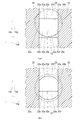
例えば、液滴検出装置20は、図11(a)に示すように、スリット25aに対して発光素子23が矢印10d方向とは反対方向(図中、上側)に偏って配置されていても良い。
液滴検出装置20は、図11(a)に示す構成である場合、端部領域22eにおける矢印10a方向での検出光の幅が矢印10c方向における一部において間隔22bと異なっており(間隔22bよりも狭くなっており)、端部領域22eにおける矢印10c方向での検出光の幅も矢印10a方向における全範囲において矢印10c方向におけるスリット25aの幅25bと異なっている。
液滴検出装置20は、図11(a)に示す構成である場合、端部領域22eにおける矢印10a方向での検出光の幅が矢印10c方向における一部において間隔22bと異なっており(間隔22bよりも狭くなっており)、端部領域22eにおける矢印10c方向での検出光の幅も矢印10a方向における全範囲において矢印10c方向におけるスリット25aの幅25bと異なっている。
また、液滴検出装置20は、端部領域22eにおいて、矢印10c方向における少なくとも一部の範囲で、矢印10a方向において壁部22aと、検出光との間に隙間を形成しないという構成である限り、スリット25aのうち矢印10c方向における端部領域22eでの検出光の幅を制限する2つの部分25fの矢印10c方向における間の幅25bが矢印10a方向における全範囲において等しいという構成でなくても良い。
例えば、液滴検出装置20は、図11(b)に示すように、スリット25aの上端25dおよび下端25eの形状が曲がっていても良い。液滴検出装置20は、図11(b)に示す構成である場合、端部領域22eにおける矢印10a方向での検出光の幅が矢印10c方向における一部において間隔22bと異なっている。
インクジェットプリンター10は、液滴検出装置20の微小液滴91の検出範囲におけるいて、微小液滴91の検出の感度の斑の発生を抑えることができるとともに、検出光が拡散して光量をロスすることが抑えられているので、ヘッド16のノズル16aの列16bの矢印10bで示す延在方向における液滴検出装置20による微小液滴91の検出範囲を延長拡張することができる。
したがって、インクジェットプリンター10は、複数のヘッド16のうち少なくとも2つのヘッド16のノズル16aの列16bの矢印10b方向における位置が互いにずれて配置されているにも関わらず、液滴検出装置20に対してヘッド16を矢印10b方向に移動させなくても、複数のヘッド16の全てのノズル16aに対して微小液滴91を検出することができる。
したがって、インクジェットプリンター10は、複数のヘッド16のうち少なくとも2つのヘッド16のノズル16aの列16bの矢印10b方向における位置が互いにずれて配置されているにも関わらず、液滴検出装置20に対してヘッド16を矢印10b方向に移動させなくても、複数のヘッド16の全てのノズル16aに対して微小液滴91を検出することができる。
なお、インクジェットプリンター10は、スタガ配列以外の配列によって複数のヘッド16の少なくとも2つの矢印10b方向における位置が互いにずれて配置されていても良い。また、インクジェットプリンター10は、全てのヘッド16の矢印10b方向における位置が等しくても良い。
10 インクジェットプリンター
10a 矢印(一対の壁部の対向方向を示す矢印)
10b 矢印(検出光の発光方向を示す矢印、光路の延在方向を示す矢印)
10c 矢印(一対の壁部の対向方向と、光路の延在方向との両方に対する直交方向を示す矢印)
10d 矢印(微小液滴の進行方向を示す矢印)
16 ヘッド
16a ノズル
16b 列
16c 幅(複数のヘッドの全体におけるノズルの列の幅)
20 液滴検出装置
20a 光路
22a 壁部
22b 間隔
22c 長さ(光路の延在方向における一対の壁部の長さ)
22d 端部
22e 端部領域(領域)
23 発光素子
24 受光素子
25a スリット
25b 幅(直交方向におけるスリットの幅)
91 微小液滴
10a 矢印(一対の壁部の対向方向を示す矢印)
10b 矢印(検出光の発光方向を示す矢印、光路の延在方向を示す矢印)
10c 矢印(一対の壁部の対向方向と、光路の延在方向との両方に対する直交方向を示す矢印)
10d 矢印(微小液滴の進行方向を示す矢印)
16 ヘッド
16a ノズル
16b 列
16c 幅(複数のヘッドの全体におけるノズルの列の幅)
20 液滴検出装置
20a 光路
22a 壁部
22b 間隔
22c 長さ(光路の延在方向における一対の壁部の長さ)
22d 端部
22e 端部領域(領域)
23 発光素子
24 受光素子
25a スリット
25b 幅(直交方向におけるスリットの幅)
91 微小液滴
Claims (7)
- インクジェットプリンターのヘッドのノズルから吐出される液滴を、当該液滴による検出光の遮りの有無に基づいて検出する液滴検出装置であって、
前記ノズルから吐出された前記液滴の進行方向と交差する方向に、前記検出光を照射する発光素子と、
前記発光素子から照射された前記検出光を受光する受光素子と、
前記液滴が通過する間隔をあけて、互いに対向して配置された一対の壁部と、を備え、
前記一対の壁部は、前記発光素子から前記受光素子までの前記検出光の光路の少なくとも一部が、前記一対の壁部の間を通過するように、前記光路に沿って設けられており、
前記光路における前記一対の壁部の間の領域では、前記検出光の少なくとも一部が、前記一対の壁部の互いの対向面で反射しながら、前記受光素子側に誘導されるようにしたことを特徴とする液滴検出装置。 - 前記一対の壁部は、当該一対の壁部の対向方向と前記検出光の光路に沿う方向とに直交する直交方向に、それぞれ所定高さを有しており、
前記検出光の前記対向方向の幅は、前記直交方向の少なくとも一部の範囲で、前記一対の壁部の前記対向方向の前記間隔と等しいことを特徴とする請求項1に記載の液滴検出装置。 - 前記一対の壁部の間には、当該一対の壁部の対向方向と前記検出光の光路に沿う方向とに直交する直交方向における前記検出光の幅を制限するスリットが形成されていることを特徴とする請求項1に記載の液滴検出装置。
- 前記スリットの前記直交方向における一方の端縁と他方の端縁は、それぞれ前記対向方向に直線状に延びると共に互いに平行に設けられており、
前記光路における前記一対の壁部の間の領域では、
前記検出光の前記対向方向の幅が、前記直交方向の全範囲で、前記一対の壁部の間の前記間隔と同じであり、
前記検出光の前記直交方向の幅が、前記対向方向の全範囲で、前記スリットの前記直交方向の幅と同じであることを特徴とする請求項3に記載の液滴検出装置。 - 前記受光素子が前記検出光を受光可能である受光可能領域の長さであって、前記一対の壁部の対向方向における長さは、前記対向方向における前記一対の壁部の間隔以上であることを特徴とする請求項1から請求項4までの何れかに記載の液滴検出装置。
- 請求項1から請求項4までの何れかに記載の液滴検出装置と、
前記液滴を吐出するノズルが前記光路に沿う方向に並んだノズル列を有する複数のヘッドと、を備え、
前記複数のヘッドは、前記光路に沿う方向における一方側に位置するヘッドと、他方側に位置するヘッドとから構成されており、
前記一対の壁部の前記光路に沿う方向の長さが、前記一方側に位置するヘッドの前記ノズル列と前記他方側に位置するヘッドの前記ノズル列とが位置する範囲の前記光路に沿う方向の長さよりも長いことを特徴とするインクジェットプリンター。 - 請求項5に記載の液滴検出装置と、
前記液滴を吐出するノズルが前記光路に沿う方向に並んだノズル列を有する複数のヘッドと、を備え、
前記複数のヘッドは、前記光路に沿う方向における一方側に位置するヘッドと、他方側に位置するヘッドとから構成されており、
前記一対の壁部の前記光路に沿う方向の長さが、前記一方側に位置するヘッドの前記ノズル列と前記他方側に位置するヘッドの前記ノズル列とが位置する範囲の前記光路に沿う方向の長さよりも長いことを特徴とするインクジェットプリンター。
Priority Applications (1)
| Application Number | Priority Date | Filing Date | Title |
|---|---|---|---|
| US15/541,710 US9956770B2 (en) | 2015-01-07 | 2016-01-07 | Droplet detection device and ink jet printer |
Applications Claiming Priority (2)
| Application Number | Priority Date | Filing Date | Title |
|---|---|---|---|
| JP2015001912A JP6356076B2 (ja) | 2015-01-07 | 2015-01-07 | 液滴検出装置およびインクジェットプリンター |
| JP2015-001912 | 2015-01-07 |
Publications (1)
| Publication Number | Publication Date |
|---|---|
| WO2016111325A1 true WO2016111325A1 (ja) | 2016-07-14 |
Family
ID=56356011
Family Applications (1)
| Application Number | Title | Priority Date | Filing Date |
|---|---|---|---|
| PCT/JP2016/050328 Ceased WO2016111325A1 (ja) | 2015-01-07 | 2016-01-07 | 液滴検出装置およびインクジェットプリンター |
Country Status (3)
| Country | Link |
|---|---|
| US (1) | US9956770B2 (ja) |
| JP (1) | JP6356076B2 (ja) |
| WO (1) | WO2016111325A1 (ja) |
Citations (3)
| Publication number | Priority date | Publication date | Assignee | Title |
|---|---|---|---|---|
| JP2006346906A (ja) * | 2005-06-14 | 2006-12-28 | Canon Inc | 液滴吐出状態検出装置、液滴吐出装置、及びインクジェット記録装置 |
| JP2009502572A (ja) * | 2005-07-28 | 2009-01-29 | イーストマン コダック カンパニー | 液滴の検出 |
| JP2010131800A (ja) * | 2008-12-03 | 2010-06-17 | Konica Minolta Ij Technologies Inc | インク滴検出装置 |
Family Cites Families (1)
| Publication number | Priority date | Publication date | Assignee | Title |
|---|---|---|---|---|
| WO2010044765A1 (en) * | 2008-10-15 | 2010-04-22 | Hewlett-Packard Development Company, L. P. | Method of detecting drops |
-
2015
- 2015-01-07 JP JP2015001912A patent/JP6356076B2/ja active Active
-
2016
- 2016-01-07 WO PCT/JP2016/050328 patent/WO2016111325A1/ja not_active Ceased
- 2016-01-07 US US15/541,710 patent/US9956770B2/en active Active
Patent Citations (3)
| Publication number | Priority date | Publication date | Assignee | Title |
|---|---|---|---|---|
| JP2006346906A (ja) * | 2005-06-14 | 2006-12-28 | Canon Inc | 液滴吐出状態検出装置、液滴吐出装置、及びインクジェット記録装置 |
| JP2009502572A (ja) * | 2005-07-28 | 2009-01-29 | イーストマン コダック カンパニー | 液滴の検出 |
| JP2010131800A (ja) * | 2008-12-03 | 2010-06-17 | Konica Minolta Ij Technologies Inc | インク滴検出装置 |
Also Published As
| Publication number | Publication date |
|---|---|
| US9956770B2 (en) | 2018-05-01 |
| US20180022090A1 (en) | 2018-01-25 |
| JP6356076B2 (ja) | 2018-07-11 |
| JP2016124262A (ja) | 2016-07-11 |
Similar Documents
| Publication | Publication Date | Title |
|---|---|---|
| US9751300B2 (en) | Testing a printhead | |
| JP2009502572A (ja) | 液滴の検出 | |
| US20010043245A1 (en) | Detection of non-operating nozzle by light beam passing through aperture | |
| JP6225517B2 (ja) | 液滴吐出状態検出装置および画像形成装置 | |
| US6641246B2 (en) | Detection of non-operating nozzle by light beam passing through aperture | |
| JP3813762B2 (ja) | 吐出インク検出装置 | |
| US7845752B2 (en) | Liquid-discharge-failure detecting apparatus and inkjet recording apparatus | |
| US8770705B2 (en) | Droplet discharge detection device and image forming apparatus including droplet discharge detection device | |
| US20130229456A1 (en) | Liquid ejecting apparatus | |
| JP4974947B2 (ja) | 液滴測定装置 | |
| WO2016111325A1 (ja) | 液滴検出装置およびインクジェットプリンター | |
| US20150177136A1 (en) | Device and method for detecting state of discharged liquid droplet and image forming device incorporating such device | |
| KR102375407B1 (ko) | 잉크젯헤드 모니터링장치 및 모니터링방법 | |
| CN107580553B (zh) | 打印头墨滴检测器 | |
| JP2007331158A (ja) | 液吐出不良検出装置、およびインクジェット記録装置 | |
| JP2009113225A (ja) | 液吐出不良検出装置、およびインクジェット記録装置 | |
| JP2007125876A (ja) | パターン形成方法及び液滴吐出装置 | |
| JP2008207338A (ja) | 液吐出不良検出装置、およびインクジェット記録装置 | |
| JP5954026B2 (ja) | 液滴吐出状態検出装置および画像形成装置 | |
| JP6519587B2 (ja) | 液滴吐出不良検出装置及びインクジェット記録装置 | |
| JP5365465B2 (ja) | 液吐出不良検出装置およびインクジェット記録装置 | |
| KR101410723B1 (ko) | 헤드 검사장치 | |
| US9676183B1 (en) | Drop detection with ribs to align emitters and detectors | |
| JP6409483B2 (ja) | 画像形成装置 | |
| JP2012192552A (ja) | 液滴吐出状態検出装置、ヘッドアレイユニットおよび画像形成装置 |
Legal Events
| Date | Code | Title | Description |
|---|---|---|---|
| 121 | Ep: the epo has been informed by wipo that ep was designated in this application |
Ref document number: 16735064 Country of ref document: EP Kind code of ref document: A1 |
|
| WWE | Wipo information: entry into national phase |
Ref document number: 15541710 Country of ref document: US |
|
| NENP | Non-entry into the national phase |
Ref country code: DE |
|
| 122 | Ep: pct application non-entry in european phase |
Ref document number: 16735064 Country of ref document: EP Kind code of ref document: A1 |