WO2016104256A1 - ガラスリボンの製造装置及びガラスリボンの製造方法 - Google Patents
ガラスリボンの製造装置及びガラスリボンの製造方法 Download PDFInfo
- Publication number
- WO2016104256A1 WO2016104256A1 PCT/JP2015/085088 JP2015085088W WO2016104256A1 WO 2016104256 A1 WO2016104256 A1 WO 2016104256A1 JP 2015085088 W JP2015085088 W JP 2015085088W WO 2016104256 A1 WO2016104256 A1 WO 2016104256A1
- Authority
- WO
- WIPO (PCT)
- Prior art keywords
- roller
- glass ribbon
- width direction
- shape
- support
- Prior art date
- Legal status (The legal status is an assumption and is not a legal conclusion. Google has not performed a legal analysis and makes no representation as to the accuracy of the status listed.)
- Ceased
Links
Images


Classifications
-
- C—CHEMISTRY; METALLURGY
- C03—GLASS; MINERAL OR SLAG WOOL
- C03B—MANUFACTURE, SHAPING, OR SUPPLEMENTARY PROCESSES
- C03B25/00—Annealing glass products
- C03B25/04—Annealing glass products in a continuous way
- C03B25/10—Annealing glass products in a continuous way with vertical displacement of the glass products
- C03B25/12—Annealing glass products in a continuous way with vertical displacement of the glass products of glass sheets
-
- C—CHEMISTRY; METALLURGY
- C03—GLASS; MINERAL OR SLAG WOOL
- C03B—MANUFACTURE, SHAPING, OR SUPPLEMENTARY PROCESSES
- C03B17/00—Forming molten glass by flowing-out, pushing-out, extruding or drawing downwardly or laterally from forming slits or by overflowing over lips
- C03B17/06—Forming glass sheets
- C03B17/064—Forming glass sheets by the overflow downdraw fusion process; Isopipes therefor
-
- C—CHEMISTRY; METALLURGY
- C03—GLASS; MINERAL OR SLAG WOOL
- C03B—MANUFACTURE, SHAPING, OR SUPPLEMENTARY PROCESSES
- C03B17/00—Forming molten glass by flowing-out, pushing-out, extruding or drawing downwardly or laterally from forming slits or by overflowing over lips
- C03B17/06—Forming glass sheets
- C03B17/067—Forming glass sheets combined with thermal conditioning of the sheets
-
- C—CHEMISTRY; METALLURGY
- C03—GLASS; MINERAL OR SLAG WOOL
- C03B—MANUFACTURE, SHAPING, OR SUPPLEMENTARY PROCESSES
- C03B17/00—Forming molten glass by flowing-out, pushing-out, extruding or drawing downwardly or laterally from forming slits or by overflowing over lips
- C03B17/06—Forming glass sheets
- C03B17/068—Means for providing the drawing force, e.g. traction or draw rollers
-
- C—CHEMISTRY; METALLURGY
- C03—GLASS; MINERAL OR SLAG WOOL
- C03B—MANUFACTURE, SHAPING, OR SUPPLEMENTARY PROCESSES
- C03B35/00—Transporting of glass products during their manufacture, e.g. hot glass lenses, prisms
- C03B35/14—Transporting hot glass sheets or ribbons, e.g. by heat-resistant conveyor belts or bands
- C03B35/16—Transporting hot glass sheets or ribbons, e.g. by heat-resistant conveyor belts or bands by roller conveyors
-
- C—CHEMISTRY; METALLURGY
- C03—GLASS; MINERAL OR SLAG WOOL
- C03B—MANUFACTURE, SHAPING, OR SUPPLEMENTARY PROCESSES
- C03B35/00—Transporting of glass products during their manufacture, e.g. hot glass lenses, prisms
- C03B35/14—Transporting hot glass sheets or ribbons, e.g. by heat-resistant conveyor belts or bands
- C03B35/16—Transporting hot glass sheets or ribbons, e.g. by heat-resistant conveyor belts or bands by roller conveyors
- C03B35/161—Transporting hot glass sheets or ribbons, e.g. by heat-resistant conveyor belts or bands by roller conveyors specially adapted for bent sheets or ribbons
-
- C—CHEMISTRY; METALLURGY
- C03—GLASS; MINERAL OR SLAG WOOL
- C03B—MANUFACTURE, SHAPING, OR SUPPLEMENTARY PROCESSES
- C03B35/00—Transporting of glass products during their manufacture, e.g. hot glass lenses, prisms
- C03B35/14—Transporting hot glass sheets or ribbons, e.g. by heat-resistant conveyor belts or bands
- C03B35/16—Transporting hot glass sheets or ribbons, e.g. by heat-resistant conveyor belts or bands by roller conveyors
- C03B35/18—Construction of the conveyor rollers ; Materials, coatings or coverings thereof
- C03B35/189—Disc rollers
-
- C—CHEMISTRY; METALLURGY
- C03—GLASS; MINERAL OR SLAG WOOL
- C03B—MANUFACTURE, SHAPING, OR SUPPLEMENTARY PROCESSES
- C03B35/00—Transporting of glass products during their manufacture, e.g. hot glass lenses, prisms
- C03B35/14—Transporting hot glass sheets or ribbons, e.g. by heat-resistant conveyor belts or bands
- C03B35/20—Transporting hot glass sheets or ribbons, e.g. by heat-resistant conveyor belts or bands by gripping tongs or supporting frames
-
- Y—GENERAL TAGGING OF NEW TECHNOLOGICAL DEVELOPMENTS; GENERAL TAGGING OF CROSS-SECTIONAL TECHNOLOGIES SPANNING OVER SEVERAL SECTIONS OF THE IPC; TECHNICAL SUBJECTS COVERED BY FORMER USPC CROSS-REFERENCE ART COLLECTIONS [XRACs] AND DIGESTS
- Y02—TECHNOLOGIES OR APPLICATIONS FOR MITIGATION OR ADAPTATION AGAINST CLIMATE CHANGE
- Y02P—CLIMATE CHANGE MITIGATION TECHNOLOGIES IN THE PRODUCTION OR PROCESSING OF GOODS
- Y02P40/00—Technologies relating to the processing of minerals
- Y02P40/50—Glass production, e.g. reusing waste heat during processing or shaping
- Y02P40/57—Improving the yield, e-g- reduction of reject rates
Definitions
- the present invention relates to a glass ribbon manufacturing apparatus and a glass ribbon manufacturing method.
- an overflow down draw method in which molten glass is flowed down from a molded body to form a glass ribbon is widely known.
- an apparatus for producing a glass ribbon using the overflow downdraw method generally cools the formed glass ribbon and a forming region where the molten glass is flowed down from the formed body to form a glass ribbon having a predetermined width.
- the glass ribbon immediately after being formed in the forming region is not yet completely solidified, and its shape is determined with the slow cooling in the annealing region.
- the process may show a tendency to bend in the width direction. It is difficult to stabilize the curved shape of such a glass ribbon, in particular, the curved direction (whether the front or back side is convex) with existing equipment, and as a result, the glass ribbon to be manufactured, and thus the glass plate, is produced. There is a possibility that the quality of the product will vary.
- the rollers that sandwich both sides of the descending glass ribbon in the width direction are inclined in the horizontal plane so as to follow the curved shape of the glass ribbon.
- the shape of the glass ribbon is stabilized.
- the support structure disclosed in Patent Document 1 is based on the premise that the glass ribbon is always in a certain bending direction (whether the front or back side is convex). Therefore, for example, when the glass ribbon begins to bend in a direction opposite to the assumed direction, the inclination direction of the roller axis is opposite to the bending direction of the glass ribbon (inclination direction at the end in the width direction). Then, when the glass ribbon is sandwiched between the rollers, a large load is applied to the glass ribbon from the rollers. Due to the load applied to the glass ribbon from this roller, the glass ribbon may be cracked.
- an object of the present invention is to stabilize the bending direction of a glass ribbon without causing cracks.
- An apparatus for producing a glass ribbon according to the present invention includes an annealing region for gradually cooling a molded glass ribbon to remove its internal strain, and the annealed glass ribbon at room temperature.
- a glass ribbon manufacturing apparatus in which a plurality of support rollers that support both sides in the width direction of the glass ribbon are disposed along the descending direction of the glass ribbon. At least one of the arranged support rollers is a shape stabilizing roller for stabilizing the shape of the glass ribbon curved in the width direction, and the shape stabilizing roller is one surface of the glass ribbon.
- a first roller having a pair of support portions disposed on the side and supporting both sides of the glass ribbon in the width direction; and disposed on the other surface side of the glass ribbon.
- a second roller having a pair of support portions for supporting both sides of the glass ribbon in the width direction, and the inner end portions in the width direction of the respective support portions of the first roller correspond to the corresponding ones. It is characterized in that it is located on the outer side in the width direction than the outer end portion in the width direction of each support portion of the second roller.
- the width direction of the glass ribbon is based on the width direction of the glass ribbon in a flat state (the same applies hereinafter).
- the inner end portions in the width direction of the respective support portions of the first roller are all positioned on the outer side in the width direction with respect to the outer end portions in the width direction of the respective support portions of the corresponding second roller. That is, it is possible to adopt a form in which the glass ribbon is supported by the second roller on the inner side in the width direction than the first roller. Thereby, it becomes possible to support the glass ribbon in a curved shape that protrudes toward the first roller as it goes inward in the width direction. Therefore, the shape of the glass ribbon curved in the width direction can be stabilized by the shape stabilizing roller.
- each support part of a 1st roller and each support part of a 2nd roller cannot be arrange
- the shape stabilizing roller can reduce the load on the glass ribbon, compared to when the rollers sandwiching both sides in the width direction of the glass ribbon are arranged in a state where the axis is inclined in the horizontal plane, The possibility that the glass ribbon is cracked can be reduced.
- the glass ribbon manufacturing apparatus of the present invention even when the glass ribbon starts to bend in the direction opposite to the assumed direction, the glass ribbon does not break, and the bending direction thereof. Can be stabilized on one side of the front and back.
- the support roller located at the uppermost position of the cooling region is the shape stabilizing roller.
- This configuration can effectively stabilize the shape of the glass ribbon curved in the width direction. This is because in the cooling region, since the glass ribbon is sufficiently solidified, the supporting force from the first and second rollers can be obtained more reliably.
- the shape stabilizing roller is further disposed in the annealing region.
- This configuration can effectively stabilize the shape of the glass ribbon curved in the width direction in the annealing region.
- the first roller in the shape stabilization roller in the annealing region is disposed on the opposite side of the glass ribbon with respect to the first roller in the shape stabilization roller in the cooling region. It is preferable.
- the bending direction of the glass ribbon once oriented in the annealing region can be reversed in the cooling region. Thereby, it can suppress that a glass ribbon is wrinkled (a curvature, bending, distortion).
- the glass ribbon is bent in the vertical direction around the portion where the bending direction is reversed. Therefore, since the periphery of this inversion part functions as a resistance that prevents bending deformation in the width direction of the glass ribbon, deformation in the width direction of the glass ribbon is difficult to occur. On the other hand, the bending in the width direction of the glass ribbon functions as a resistance for preventing the bending deformation in the vertical direction of the glass ribbon, so that the vertical deformation of the glass ribbon is difficult to occur. Due to these synergistic effects, the glass ribbon is suppressed from being deformed in the width direction and the vertical direction. Thereby, the malfunction that a glass ribbon disturbs an attitude
- an auxiliary roller for stabilizing the shape of the glass ribbon that is curved in the width direction in the annealing region is disposed below the shape stabilizing roller, and the auxiliary roller is provided.
- the roller is composed of the first roller and the second roller, and the interval in the thickness direction of the glass ribbon between the first roller and the second roller in the auxiliary roller is the shape stability of the annealing region. It is preferable that the gap between the first roller and the second roller in the thickness direction is larger than the distance in the thickness direction.
- the thickness direction of the glass ribbon is based on the thickness direction of the glass ribbon in a flat state (hereinafter the same).
- the auxiliary roller can contact and support the glass ribbon only when the curved shape and position of the glass ribbon are likely to change greatly, and can suppress changes in the curved shape and position of the glass ribbon. . For this reason, since the contact to the glass ribbon of an auxiliary roller can be suppressed, it can suppress that the load by contact is applied to a glass ribbon.
- the first roller in the shape stabilization roller in the annealing region is disposed on the opposite surface side of the glass ribbon with respect to the first roller in the shape stabilization roller in the cooling region. It is preferable that the first roller in the auxiliary roller is disposed on the same surface side of the glass ribbon with respect to the first roller in the shape stabilizing roller in the cooling region.
- the direction of bending in the width direction of the glass ribbon can be reversed between the cooling region and the annealing region.
- the curved shape of the glass ribbon can be matched to some extent with the curved shape in the cooling region before the glass ribbon descends to the cooling region by the auxiliary roller. Thereby, the direction of curve of the glass ribbon is gently reversed, and the load applied to the glass ribbon can be reduced by reversing the direction of curve of the glass ribbon.
- the support roller for sandwiching both sides in the width direction of the glass ribbon in the annealing region is disposed between the shape stabilizing roller and the auxiliary roller.
- the rollers that sandwich both sides of the glass ribbon in the width direction in the annealing region can suppress shaking at both ends of the glass ribbon in the width direction, and effectively stabilize the curved shape of the glass ribbon. Can do.
- the support roller for sandwiching both sides of the glass ribbon in the width direction in the cooling region is disposed below the shape stabilizing roller.
- the rollers sandwiching both sides in the width direction of the glass ribbon can suppress the shaking at both ends in the width direction of the glass ribbon, and effectively stabilize the curved shape of the glass ribbon. Can do.
- the glass ribbon manufacturing method includes an annealing step of gradually cooling a molded glass ribbon to remove its internal strain, and the slowly cooling glass ribbon at room temperature.
- At least one of the arranged support rollers is a shape stabilizing roller for stabilizing the shape of the glass ribbon curved in the width direction, and the shape stabilizing roller is one surface of the glass ribbon.
- a first roller having a pair of support portions disposed on the side and supporting both sides of the glass ribbon in the width direction; and disposed on the other surface side of the glass ribbon.
- a second roller having a pair of support portions for supporting both sides of the glass ribbon in the width direction, and the inner end portions in the width direction of the respective support portions of the first roller correspond to the corresponding ones. It is characterized in that it is located on the outer side in the width direction than the outer end portion in the width direction of each support portion of the second roller.
- the bending direction can be stabilized without causing a crack in the glass ribbon.
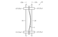
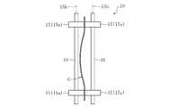
- FIG. 2 is a cross-sectional view taken along line AA in FIG. 1 and is a schematic plan view showing a shape stabilizing roller.
- FIG. 2 is a cross-sectional view taken along line DD of FIG. 1 and is a schematic plan view showing a shape stabilizing roller.
- FIG. 2 is a cross-sectional view taken along the line CC of FIG. 1 and is a schematic plan view showing an auxiliary roller.
- FIG. 2 is a cross-sectional view taken along the line BB in FIG. 1 and is a schematic plan view showing a clamping roller.
- FIG. 2 is a cross-sectional view taken along line EE in FIG. 1 and is a schematic plan view showing a pinching roller.
- FIG. 1 is a schematic longitudinal sectional view showing a glass ribbon manufacturing apparatus 1 according to an embodiment of the present invention.
- the glass ribbon manufacturing apparatus 1 forms a plate-like glass ribbon G that is a base of a glass plate by an overflow down draw method.
- Glass plates produced by cutting the glass ribbon G include, for example, flat panel displays such as liquid crystal displays, plasma displays, and organic EL displays, solar cells, lithium ion batteries, digital signage, touch panels, and electronic paper. It is used for device glass substrates, cover glasses for organic EL lighting, pharmaceutical glass containers, window glass, laminated lightweight window glass, and the like.
- the thickness of the central portion in the width direction of the glass ribbon G is preferably 10 ⁇ m to 2 mm.
- the thickness of the glass ribbon G is less than 10 ⁇ m, it may be difficult to form the glass ribbon G itself.
- the thickness of the glass ribbon G exceeds 2 mm, there is little tendency for the shape and posture to fluctuate, and the present invention may not be effective. From these viewpoints, the thickness of the central portion in the width direction of the glass ribbon G is more preferably 20 ⁇ m to 1 mm, and most preferably 30 ⁇ m to 500 ⁇ m.
- the width of the glass ribbon G is preferably 250 mm to 3000 mm. When the width of the glass ribbon G is less than 250 mm, there is little tendency to bend in the width direction, and the present invention may not be effective. If the width of the glass ribbon G exceeds 3000 mm, it may be difficult to manufacture. From these viewpoints, the width of the glass ribbon G is more preferably 280 mm to 2500 mm, and most preferably 300 mm to 2000 mm.
- the glass ribbon manufacturing apparatus 1 includes, in order from the top, a forming region 2 for performing a forming step, an annealing region 3 for performing an annealing step, and a cooling region 4 for performing a cooling step.
- the molten glass Gm is supplied to the molded body 5 having a wedge-shaped cross-sectional shape, and the molten glass Gm overflowing from the top of the molded body 5 is merged at the lower end to flow down.
- a band-shaped glass ribbon G is formed from the glass Gm.
- the glass ribbon G is sandwiched on both sides in the width direction by the cooling roller 6 in the forming region 2 and the shrinkage in the width direction is suppressed.
- the internal strain is removed while the glass ribbon G formed in the forming region 2 is slowly cooled.
- the glass ribbon G that has been gradually cooled in the annealing region 3 is cooled to near room temperature. The glass ribbon G descends from the molding region 2 to the cooling region 4.
- a plurality of support rollers 7 that support both sides of the glass ribbon G in the width direction are disposed in the annealing region 3 and the cooling region 4 along the descending direction of the glass ribbon G.
- the support roller 7 disposed in the annealing region 3 is made of a heat-resistant material, for example, an inorganic material containing ceramic fibers and a binder.
- the support roller 7 disposed in the cooling region 4 has a surface layer made of an elastic member such as silicone rubber.
- one of the support rollers 7 disposed in the annealing region 3 is a shape stabilizing roller 8 for stabilizing the shape of the glass ribbon G curved in the width direction.
- a part of the support roller 7 disposed below the shape stabilization roller 8 is supplemented by an auxiliary roller 9 for stabilizing the shape of the glass ribbon G that is curved in the width direction. It has become.
- the support roller 7 disposed above the shape stabilizing roller 8 and between the shape stabilizing roller 8 and the auxiliary roller 9 sandwiches both sides in the width direction of the glass ribbon G. This is a sandwiching roller 10.
- the uppermost support roller 7 is a shape stabilizing roller 8. Further, the supporting roller 7 disposed below the shape stabilizing roller 8 in the cooling region 4 is a sandwiching roller 10.
- the shape stabilizing roller 8 includes a first roller 11 disposed on one surface side of the glass ribbon G and a second roller disposed on the other surface side of the glass ribbon G. It is comprised with the roller 12.
- FIG. The first roller 11 has a pair of rollers 11a (supporting portions) that support both sides of the glass ribbon G in the width direction.
- the roller 11a is arranged coaxially.
- the 2nd roller 12 has a pair of roller 12a (support part) which supports the both sides of the width direction of the glass ribbon G. As shown in FIG.
- the roller 12a is disposed coaxially.
- the pair of rollers 11a is connected and fixed to the first roller shaft 13 and the pair of rollers 12a is connected and fixed to the second roller shaft 14.
- the individual rollers 11a and rollers 12a may be cantilevered.
- the first roller 11 is composed of a pair of rollers 11a
- the second roller 12 is composed of a pair of rollers 12a.
- each of the first roller 11 and the second roller is long in the width direction of the glass ribbon G, and a pair of supporting the glass ribbon G at both ends in the width direction by providing a recess in the center in the width direction. You may be comprised with the single roller which provided the support part.
- the first roller 11 and the second roller 12 are disposed at the same height.
- the axis 11b of the first roller 11 (axis of the roller 11a) and the axis 12b of the second roller 12 (axis of the roller 12a) extend in the horizontal direction and are parallel to each other.
- the pair of rollers 11a constituting the first roller 11 and the pair of rollers 12a constituting the second roller 12 all have the same shape and the same dimensions.
- the center between the pair of rollers 11a and the center between the pair of rollers 12a are at the same position.
- the inner end portion 11 c in the width direction of the glass ribbon G in each roller 11 a of the first roller 11 corresponds to the second side (on the same side in the width direction of the glass ribbon G).
- the roller 12a of the roller 12 is positioned on the outer side in the width direction of the glass ribbon G with respect to the outer end portion 12c in the width direction of the glass ribbon G.
- the end-to-end distance D1 between the rollers 11a, the inner end 11c, and the outer end 12c of the corresponding roller 12a in the direction of the axis 11b, 12b (the width direction of the glass ribbon G) is preferably 20 to 100 mm.
- the roller 11a and the roller 12a on the same side are close to each other, so that the portion of the glass ribbon G positioned between them is excessive (for example, inclined) with respect to the axes 11b and 12b. Inclined at an angle of 20 ° or more, there is a possibility of undue stress being generated at this portion and being damaged.
- the distance D1 between the end portions exceeds 100 mm, the one-side roller 11a and the one-side roller 12a become far away, so that the glass ribbon G cannot be sufficiently supported and the curved shape may not be stabilized.
- the end-to-end distance D1 is more preferably 20 mm to 50 mm, and most preferably 20 mm to 40 mm.
- part which the rollers 11a and 12a contact with the glass ribbon G is square in the example of illustration, it is preferable that the chamfering process is carried out in the curved surface shape. In this case, the area where the rollers 11a and 12a contact the glass ribbon G can be increased. Thereby, in addition to enhancing the holding power of the shape of the glass ribbon G, the glass ribbon G does not make point contact with the rollers 11a and 12a, so that it is possible to suppress the occurrence of cracks in the glass ribbon G.
- the shape stabilizing roller 8 disposed in the cooling region 4 is disposed in the annealing region. 3, the grip force with respect to the glass ribbon G is higher than that of the shape stabilizing roller 8 disposed in the shape 3, and the curved shape of the glass ribbon G can be effectively stabilized.
- the distance D2 in the thickness direction of the glass ribbon G between the roller 11a of the first roller 11 and the roller 12a of the second roller 12 (direction perpendicular to the axes 11b and 12b) in the shape stabilizing roller 8 is -10 mm to 7 mm is preferred.
- the direction in which the first roller 11 and the second roller 12 are separated from each other is positive.
- the distance D2 is less than ⁇ 10 mm, an excessive load is applied to the portion of the glass ribbon G located between the one-side roller 11a and the one-side roller 12a, which may cause damage.
- the distance D2 exceeds 7 mm, the glass ribbon G cannot be sufficiently supported, and the curved shape may not be stabilized. From these viewpoints, the distance D2 is more preferably ⁇ 7 mm to 5 mm, and most preferably ⁇ 5 mm to 3 mm.
- the shape stabilizing roller 8 when the shape stabilizing roller 8 is disposed in the annealing region 3, it is preferably disposed below the annealing region 3. This is because the glass ribbon G is not sufficiently solidified above the annealing region 3 and may not be sufficiently supported by the shape stabilizing roller 8, and the glass ribbon G may not be sufficiently supported above the annealing region 3. This is because the ribbon G may not be curved in the width direction yet.
- the number of the shape stabilizing rollers 8 is preferably 5% or more of the number of rollers excluding the auxiliary roller 9 disposed in the annealing region 3 and the cooling region 4.
- the number of the shape stabilizing rollers 8 is more preferably 8% or more, and most preferably 10% or more, out of the number of rollers excluding the auxiliary roller 9 disposed in the annealing region 3 and the cooling region 4.
- the number of the shape stabilizing rollers 8 is preferably 40% or less of the number of rollers excluding the auxiliary roller 9 disposed in the annealing region 3 and the cooling region 4. This is because if the number of the shape stabilizing rollers 8 exceeds 40%, the effect of the sandwiching rollers 10 may not be sufficiently obtained.
- the effect of the sandwiching roller 10 is to suppress the shrinkage in the width direction of the glass ribbon G when disposed above the annealing region, in addition to the suppression of the shaking at both ends in the width direction of the glass ribbon G.
- the number of the shape stabilizing rollers 8 is more preferably 35% or less, and most preferably 30% or less, out of the number of rollers excluding the auxiliary roller 9 disposed in the annealing region 3 and the cooling region 4.
- the auxiliary roller 9 is arranged on the other surface side of the glass ribbon G and the first roller 11 arranged on the one surface side of the glass ribbon G, similarly to the shape stabilizing roller 8.
- the second roller 12 is made up of.
- the auxiliary roller 9 is different from the shape stabilizing roller 8 in that the thickness direction (perpendicular to the axes 11b and 12b) of the glass ribbon G between the roller 11a of the first roller 11 and the roller 12a of the second roller 12 in the auxiliary roller 9 is different.
- the distance D3 in the right direction) is larger than the distance D2 in the shape stabilizing roller 8 in the annealing region 3. Since the distance D3 is larger than the distance D2, the auxiliary roller 9 comes into contact with the glass ribbon G only when the curved shape and position of the glass ribbon G are likely to change greatly.
- the other configuration is the same as that of the shape stabilizing roller 8, and the description thereof is omitted.
- the difference between the distance D3 of the auxiliary roller 9 and the distance D2 of the shape stabilizing roller 8 is preferably 0.5 mm to 3 mm.
- the difference between the distance D3 and the distance D2 is less than 0.5 mm, the glass ribbon G frequently contacts the first roller 11 and the second roller 12 of the auxiliary roller 9, and the load caused by the contact with the glass ribbon G is inappropriate. May occur.
- the difference between the distance D3 and the distance D2 exceeds 3 mm, the glass ribbon G can hardly contact the first roller 11 and the second roller 12 of the auxiliary roller 9, and the curved shape of the glass ribbon G may not be stabilized. Sex occurs.
- the difference between the distance D3 and the distance D2 is more preferably 0.5 mm to 2 mm, and most preferably 0.5 mm to 1 mm.
- the sandwiching roller 10 is composed of a pair of rollers 15, 15 arranged on the front and back surfaces of the glass ribbon G.
- Each roller 15 has a pair of rollers 15a (support portions) that support both sides of the glass ribbon G in the width direction.
- the roller 15a is arranged coaxially.
- the pair of rollers 15a are connected and fixed to the roller shaft 16, but of course, the individual rollers 15a may be cantilevered.
- the roller 15 is composed of a pair of rollers 15a.
- the roller 15 is long in the width direction of the glass ribbon G, and is provided with a recess at the center in the width direction. It may be configured by a single roller provided with a pair of support portions for supporting the glass ribbon G at both ends of the.
- the roller 15 on one side of the glass ribbon G and the roller 15 on the other side are disposed at the same height.
- the axis 15b of the roller 15 on one surface side and the axis 15b of the roller 15 on the other surface side extend in the horizontal direction and are parallel to each other.
- the pair of rollers 15a constituting the roller 15 on one surface side and the pair of rollers 15a constituting the roller 15 on the other surface side all have the same shape and the same dimensions.
- the sandwiching roller 10 sandwiches the end in the width direction of the glass ribbon G from the front and back with the roller 15a on one surface side and the roller 15a on the other surface side on one side in the width direction of the glass ribbon G. Further, the sandwiching roller 10 sandwiches the end portion in the width direction of the glass ribbon G from the front and back with the roller 15a on one surface side and the roller 15a on the other surface side on the other side in the width direction of the glass ribbon G.
- the first roller 11 in the shape stabilizing roller 8 in the annealing region 3 is the opposite surface of the glass ribbon G to the first roller 11 in the shape stabilizing roller 8 in the cooling region 4.
- the second roller 12 in the shape stabilizing roller 8 in the annealing region 3 is disposed on the opposite side of the glass ribbon G with respect to the second roller 12 in the shape stabilizing roller 8 in the cooling region 4. Has been placed.
- the first roller 11 in the auxiliary roller 9 is disposed on the same surface side of the glass ribbon G with respect to the first roller 11 in the shape stabilizing roller 8 in the cooling region 4.
- the second roller 12 in the auxiliary roller 9 is disposed on the same surface side of the glass ribbon G with respect to the second roller 12 in the shape stabilizing roller 8 in the cooling region 4.
- the bending direction in the width direction of the glass ribbon G is reversed between the annealing region 3 and the cooling region 4. It becomes.
- the shape stabilizing roller 8, the auxiliary roller 9, and the sandwiching roller 10 are preferably all driven to rotate, but some of them may be driven. In the case of rotational driving, it is preferable that the rotational speeds of the shape stabilizing roller 8, the auxiliary roller 9, and the sandwiching roller 10 are all the same.
- the glass ribbon manufacturing apparatus 1 configured as described above can enjoy the following effects.
- the inner end portions 11 c of the respective rollers 11 a of the first roller 11 are all more outward in the width direction of the glass ribbon G than the outer end portions 12 c of the respective rollers 12 a of the corresponding second roller 12.
- the shape stabilizing roller 8 can stabilize the shape of the glass ribbon G curved in the width direction.
- rollers 11a of the first roller 11 and the rollers 12a of the second roller 12 of the shape stabilizing roller 8 cannot be arranged to face each other with the glass ribbon G interposed therebetween. That is, each roller 11a of the first roller 11 and each roller 12a of the second roller 12 do not take a form of sandwiching a predetermined width direction region on both sides of the glass ribbon G in the width direction. For this reason, when the glass ribbon G starts to bend in a direction opposite to the assumed direction, the glass ribbon G is supported by the shape stabilizing roller 8 when the glass ribbon G is supported by the shape stabilizing roller 8.
- the shape stabilizing roller 8 can reduce the load applied to the glass ribbon G as compared with the case where the rollers sandwiching both sides in the width direction of the glass ribbon are arranged in a state where the axis is inclined in the horizontal plane. It is possible to reduce the possibility of the glass ribbon G being cracked. Thus, in the glass ribbon manufacturing apparatus 1 of the present embodiment, even when the glass ribbon G starts to bend in a direction opposite to the assumed direction, the glass ribbon G is not cracked. The bending direction can be stabilized on one side of the front and back.
- the shape stabilizing roller is disposed in each of the annealing region and the cooling region.
- one shape stabilizing roller may be provided in the annealing region and the cooling region.
- the glass ribbon is formed by the overflow down draw method.
- the glass ribbon may be formed by other methods such as a slot down draw method and a redraw method.
Landscapes
- Chemical & Material Sciences (AREA)
- Engineering & Computer Science (AREA)
- Materials Engineering (AREA)
- Organic Chemistry (AREA)
- Re-Forming, After-Treatment, Cutting And Transporting Of Glass Products (AREA)
Abstract
Description
3 アニール領域
4 冷却領域
7 支持ローラ
8 形状安定化ローラ
9 補助ローラ
10 挟持ローラ
11 第1ローラ
11a ローラ(支持部)
11b 軸線
11c 内側端部
12 第2ローラ
12a ローラ(支持部)
12b 軸線
12c 外側端部
D2 第1ローラと第2ローラの間隔
D3 第1ローラと第2ローラの間隔
G ガラスリボン
Claims (9)
- 成形されたガラスリボンを徐冷してその内部歪を除去するアニール領域と、徐冷された前記ガラスリボンを室温付近まで冷却する冷却領域とを備え、これらの領域で、前記ガラスリボンの幅方向の両側を支持する支持ローラを前記ガラスリボンの下降方向に沿って複数配設したガラスリボンの製造装置において、
複数配設された前記支持ローラの少なくとも1つが、前記幅方向で湾曲した前記ガラスリボンの形状を安定化させるための形状安定化ローラであり、
前記形状安定化ローラは、前記ガラスリボンの一方の面側に配置され、前記ガラスリボンの前記幅方向の両側を支持する一対の支持部を有する第1ローラと、前記ガラスリボンの他方の面側に配置され、前記ガラスリボンの前記幅方向の両側を支持する一対の支持部を有する第2ローラとで構成され、
前記第1ローラの各支持部の前記幅方向の内側端部が何れも、対応する前記第2ローラの各支持部の前記幅方向の外側端部よりも前記幅方向の外側に位置することを特徴とするガラスリボンの製造装置。 - 前記冷却領域の最も上方に位置する前記支持ローラが、前記形状安定化ローラであることを特徴とする請求項1に記載のガラスリボンの製造装置。
- さらに、前記アニール領域に、前記形状安定化ローラが配設されていることを特徴とする請求項2に記載のガラスリボンの製造装置。
- 前記アニール領域の前記形状安定化ローラにおける前記第1ローラが、前記冷却領域の前記形状安定化ローラにおける前記第1ローラに対して前記ガラスリボンの逆の面側に配置されていることを特徴とする請求項3に記載のガラスリボンの製造装置。
- 前記アニール領域で、補助的に前記幅方向で湾曲した前記ガラスリボンの形状を安定化させるための補助ローラが、前記形状安定化ローラより下方に配設されており、
前記補助ローラは、前記第1ローラと前記第2ローラとで構成され、
前記補助ローラにおける前記第1ローラと前記第2ローラとの前記ガラスリボンの厚さ方向の間隔は、前記アニール領域の前記形状安定化ローラにおける前記第1ローラと前記第2ローラとの前記厚さ方向の間隔より大きいことを特徴とする請求項3に記載のガラスリボンの製造装置。 - 前記アニール領域の前記形状安定化ローラにおける前記第1ローラが、前記冷却領域の前記形状安定化ローラにおける前記第1ローラに対して前記ガラスリボンの逆の面側に配置されており、
前記補助ローラにおける前記第1ローラが、前記冷却領域の前記形状安定化ローラにおける前記第1ローラに対して前記ガラスリボンの同じ面側に配置されていることを特徴とする請求項5に記載のガラスリボンの製造装置。 - 前記アニール領域で、前記ガラスリボンの前記幅方向の両側を挟持するための前記支持ローラが、前記形状安定化ローラと前記補助ローラとの間に配設されていることを特徴とする請求項5又は6に記載のガラスリボンの製造装置。
- 前記冷却領域で、前記ガラスリボンの前記幅方向の両側を挟持するための前記支持ローラが、前記形状安定化ローラの下方に配設されていることを特徴とする請求項2~7の何れか1項に記載のガラスリボンの製造装置。
- 成形されたガラスリボンを徐冷してその内部歪を除去するアニール工程と、徐冷された前記ガラスリボンを室温付近まで冷却する冷却工程とを備え、これらの工程で、前記ガラスリボンの幅方向の両側を支持する支持ローラを前記ガラスリボンの下降方向に沿って複数配設したガラスリボンの製造方法において、
複数配設された前記支持ローラの少なくとも1つが、前記幅方向で湾曲した前記ガラスリボンの形状を安定化させるための形状安定化ローラであり、
前記形状安定化ローラは、前記ガラスリボンの一方の面側に配置され、前記ガラスリボンの前記幅方向の両側を支持する一対の支持部を有する第1ローラと、前記ガラスリボンの他方の面側に配置され、前記ガラスリボンの前記幅方向の両側を支持する一対の支持部を有する第2ローラとで構成され、
前記第1ローラの各支持部の前記幅方向の内側端部が何れも、対応する前記第2ローラの各支持部の前記幅方向の外側端部よりも前記幅方向の外側に位置することを特徴とするガラスリボンの製造方法。
Priority Applications (3)
| Application Number | Priority Date | Filing Date | Title |
|---|---|---|---|
| US15/529,261 US10501360B2 (en) | 2014-12-22 | 2015-12-15 | Glass ribbon manufacturing apparatus and method for manufacturing glass ribbon |
| CN201580044584.5A CN106573817A (zh) | 2014-12-22 | 2015-12-15 | 玻璃带的制造装置以及玻璃带的制造方法 |
| KR1020177003650A KR20170099830A (ko) | 2014-12-22 | 2015-12-15 | 유리 리본의 제조 장치 및 유리 리본의 제조 방법 |
Applications Claiming Priority (2)
| Application Number | Priority Date | Filing Date | Title |
|---|---|---|---|
| JP2014-258895 | 2014-12-22 | ||
| JP2014258895A JP6388210B2 (ja) | 2014-12-22 | 2014-12-22 | ガラスリボンの製造装置及びガラスリボンの製造方法 |
Publications (1)
| Publication Number | Publication Date |
|---|---|
| WO2016104256A1 true WO2016104256A1 (ja) | 2016-06-30 |
Family
ID=56150281
Family Applications (1)
| Application Number | Title | Priority Date | Filing Date |
|---|---|---|---|
| PCT/JP2015/085088 Ceased WO2016104256A1 (ja) | 2014-12-22 | 2015-12-15 | ガラスリボンの製造装置及びガラスリボンの製造方法 |
Country Status (5)
| Country | Link |
|---|---|
| US (1) | US10501360B2 (ja) |
| JP (1) | JP6388210B2 (ja) |
| KR (1) | KR20170099830A (ja) |
| CN (1) | CN106573817A (ja) |
| WO (1) | WO2016104256A1 (ja) |
Families Citing this family (4)
| Publication number | Priority date | Publication date | Assignee | Title |
|---|---|---|---|---|
| JP7010644B2 (ja) * | 2017-09-29 | 2022-01-26 | AvanStrate株式会社 | ガラス基板の製造方法、及びガラス基板製造装置 |
| CN112912349A (zh) * | 2018-10-05 | 2021-06-04 | 康宁公司 | 具有注射端口和抽取端口的玻璃形成装置和使用所述玻璃形成装置来冷却玻璃的方法 |
| US11414337B2 (en) | 2019-08-29 | 2022-08-16 | Owens-Brockway Glass Container Inc. | Forming glass containers from tubular parisons |
| WO2021202515A1 (en) * | 2020-03-31 | 2021-10-07 | Corning Incorporated | Versatile glass forming and processing system with 3-d vacuum forming capability |
Citations (5)
| Publication number | Priority date | Publication date | Assignee | Title |
|---|---|---|---|---|
| JP2001031435A (ja) * | 1999-07-22 | 2001-02-06 | Nh Techno Glass Kk | ガラス板の製造方法、ガラス板の製造装置、及び液晶デバイス |
| JP2011098884A (ja) * | 2009-10-29 | 2011-05-19 | Corning Inc | 力の循環を最小限に抑える低摩擦エッジローラ |
| JP2012041244A (ja) * | 2010-08-23 | 2012-03-01 | Nippon Electric Glass Co Ltd | ガラス板の製造方法 |
| JP2012519136A (ja) * | 2009-02-27 | 2012-08-23 | コーニング インコーポレイテッド | ガラスリボン上の領域を成形する方法 |
| WO2012132454A1 (ja) * | 2011-03-30 | 2012-10-04 | AvanStrate株式会社 | ガラス板の製造方法及びガラス板製造装置 |
Family Cites Families (6)
| Publication number | Priority date | Publication date | Assignee | Title |
|---|---|---|---|---|
| US1514385A (en) * | 1921-08-09 | 1924-11-04 | Hitchcock Experiment Company | Leer |
| US8899078B2 (en) | 2008-11-26 | 2014-12-02 | Corning Incorporated | Glass sheet stabilizing system, glass manufacturing system and method for making a glass sheet |
| KR101736262B1 (ko) * | 2010-02-18 | 2017-05-16 | 니폰 덴키 가라스 가부시키가이샤 | 유리 필름의 제조방법 및 그 제조장치 |
| WO2012004625A1 (en) * | 2010-07-08 | 2012-01-12 | Corning Incorporated | Apparatus and method for continuous shaping of a glass ribbon |
| US9027815B2 (en) * | 2010-08-31 | 2015-05-12 | Corning Incorporated | Apparatus and method for making glass sheet with improved sheet stability |
| JP5669006B2 (ja) * | 2010-10-19 | 2015-02-12 | 日本電気硝子株式会社 | 帯状ガラスフィルム製造方法及び帯状ガラスフィルム製造装置 |
-
2014
- 2014-12-22 JP JP2014258895A patent/JP6388210B2/ja active Active
-
2015
- 2015-12-15 CN CN201580044584.5A patent/CN106573817A/zh active Pending
- 2015-12-15 KR KR1020177003650A patent/KR20170099830A/ko not_active Withdrawn
- 2015-12-15 US US15/529,261 patent/US10501360B2/en active Active
- 2015-12-15 WO PCT/JP2015/085088 patent/WO2016104256A1/ja not_active Ceased
Patent Citations (5)
| Publication number | Priority date | Publication date | Assignee | Title |
|---|---|---|---|---|
| JP2001031435A (ja) * | 1999-07-22 | 2001-02-06 | Nh Techno Glass Kk | ガラス板の製造方法、ガラス板の製造装置、及び液晶デバイス |
| JP2012519136A (ja) * | 2009-02-27 | 2012-08-23 | コーニング インコーポレイテッド | ガラスリボン上の領域を成形する方法 |
| JP2011098884A (ja) * | 2009-10-29 | 2011-05-19 | Corning Inc | 力の循環を最小限に抑える低摩擦エッジローラ |
| JP2012041244A (ja) * | 2010-08-23 | 2012-03-01 | Nippon Electric Glass Co Ltd | ガラス板の製造方法 |
| WO2012132454A1 (ja) * | 2011-03-30 | 2012-10-04 | AvanStrate株式会社 | ガラス板の製造方法及びガラス板製造装置 |
Also Published As
| Publication number | Publication date |
|---|---|
| JP6388210B2 (ja) | 2018-09-12 |
| KR20170099830A (ko) | 2017-09-01 |
| US20170260078A1 (en) | 2017-09-14 |
| JP2016117623A (ja) | 2016-06-30 |
| CN106573817A (zh) | 2017-04-19 |
| US10501360B2 (en) | 2019-12-10 |
Similar Documents
| Publication | Publication Date | Title |
|---|---|---|
| US9212079B2 (en) | Methods and apparatus for reducing stress variations in glass sheets produced from a glass ribbon | |
| JP5652742B2 (ja) | 強化板ガラス及びその製造方法 | |
| CN101528618B (zh) | 玻璃带的制造装置及其制造方法 | |
| KR101833809B1 (ko) | 유리판의 제조 방법 | |
| CN105121368B (zh) | 带保持部的玻璃基板、玻璃基板的热处理方法、以及玻璃基板支承单元 | |
| CN107408560A (zh) | 玻璃基板和包括所述玻璃基板的显示设备 | |
| JP5016606B2 (ja) | 帯状ガラスから製造されたガラスシートにおける応力偏差を低減する方法および装置 | |
| JP6388210B2 (ja) | ガラスリボンの製造装置及びガラスリボンの製造方法 | |
| CN105722676B (zh) | 玻璃膜层叠体及液晶面板的制造方法 | |
| JP2014005170A (ja) | ガラス板の製造方法 | |
| TW201217284A (en) | Apparatus and method for making glass sheet with improved sheet stability | |
| JP2011207721A (ja) | ガラスフィルムの切断方法及びガラスロールの製造方法 | |
| JP5241223B2 (ja) | ガラス板の製造方法及び製造設備 | |
| JP2012167014A (ja) | ガラス板の製造方法及び製造設備 | |
| TWI681939B (zh) | 玻璃薄膜的製造方法、及包含玻璃薄膜的電子裝置的製造方法 | |
| JP2015224171A (ja) | ガラス基板の製造方法 | |
| WO2014178405A1 (ja) | ガラスフィルム積層体および電子デバイスの製造方法 | |
| JP2016060135A (ja) | ガラスフィルム積層体、及び、電子デバイスの製造方法 | |
| TW201500189A (zh) | 可撓性玻璃基板之溫度輔助處理 |
Legal Events
| Date | Code | Title | Description |
|---|---|---|---|
| 121 | Ep: the epo has been informed by wipo that ep was designated in this application |
Ref document number: 15872825 Country of ref document: EP Kind code of ref document: A1 |
|
| ENP | Entry into the national phase |
Ref document number: 20177003650 Country of ref document: KR Kind code of ref document: A |
|
| WWE | Wipo information: entry into national phase |
Ref document number: 15529261 Country of ref document: US |
|
| NENP | Non-entry into the national phase |
Ref country code: DE |
|
| 122 | Ep: pct application non-entry in european phase |
Ref document number: 15872825 Country of ref document: EP Kind code of ref document: A1 |