WO2016104187A1 - 自走式芝刈機 - Google Patents
自走式芝刈機 Download PDFInfo
- Publication number
- WO2016104187A1 WO2016104187A1 PCT/JP2015/084800 JP2015084800W WO2016104187A1 WO 2016104187 A1 WO2016104187 A1 WO 2016104187A1 JP 2015084800 W JP2015084800 W JP 2015084800W WO 2016104187 A1 WO2016104187 A1 WO 2016104187A1
- Authority
- WO
- WIPO (PCT)
- Prior art keywords
- self
- lawn mower
- storage battery
- charging
- voltage
- Prior art date
- Legal status (The legal status is an assumption and is not a legal conclusion. Google has not performed a legal analysis and makes no representation as to the accuracy of the status listed.)
- Ceased
Links
Images






Classifications
-
- A—HUMAN NECESSITIES
- A01—AGRICULTURE; FORESTRY; ANIMAL HUSBANDRY; HUNTING; TRAPPING; FISHING
- A01D—HARVESTING; MOWING
- A01D34/00—Mowers; Mowing apparatus of harvesters
- A01D34/01—Mowers; Mowing apparatus of harvesters characterised by features relating to the type of cutting apparatus
- A01D34/412—Mowers; Mowing apparatus of harvesters characterised by features relating to the type of cutting apparatus having rotating cutters
- A01D34/63—Mowers; Mowing apparatus of harvesters characterised by features relating to the type of cutting apparatus having rotating cutters having cutters rotating about a vertical axis
- A01D34/76—Driving mechanisms for the cutters
- A01D34/78—Driving mechanisms for the cutters electric
-
- A—HUMAN NECESSITIES
- A01—AGRICULTURE; FORESTRY; ANIMAL HUSBANDRY; HUNTING; TRAPPING; FISHING
- A01D—HARVESTING; MOWING
- A01D34/00—Mowers; Mowing apparatus of harvesters
- A01D34/006—Control or measuring arrangements
- A01D34/008—Control or measuring arrangements for automated or remotely controlled operation
-
- Y—GENERAL TAGGING OF NEW TECHNOLOGICAL DEVELOPMENTS; GENERAL TAGGING OF CROSS-SECTIONAL TECHNOLOGIES SPANNING OVER SEVERAL SECTIONS OF THE IPC; TECHNICAL SUBJECTS COVERED BY FORMER USPC CROSS-REFERENCE ART COLLECTIONS [XRACs] AND DIGESTS
- Y02—TECHNOLOGIES OR APPLICATIONS FOR MITIGATION OR ADAPTATION AGAINST CLIMATE CHANGE
- Y02T—CLIMATE CHANGE MITIGATION TECHNOLOGIES RELATED TO TRANSPORTATION
- Y02T10/00—Road transport of goods or passengers
- Y02T10/60—Other road transportation technologies with climate change mitigation effect
- Y02T10/72—Electric energy management in electromobility
Definitions
- the present invention relates to a self-propelled lawn mower that operates with electric power from a storage battery.
- Patent Document 1 discloses control of a self-propelled lawn mower.
- Patent Document 2 discloses a configuration of a charging device for a self-propelled device.
- the present invention has been made in view of such a situation, and a first object of the present invention is a self-propelled lawn mower that can reliably charge a storage battery to a full charge as compared with the prior art and is advantageous for cost reduction. Is to provide a machine.
- the second object of the present invention is that a storage battery as a power supply source to a motor can be detachably attached, and a storage battery with a reduced remaining battery capacity is replaced with a charged storage battery.
- a self-propelled lawn mower that can continue the lawn mowing work by replacing the storage battery.
- a third object of the present invention is to provide a self-propelled mower capable of reliably stopping charging of a storage battery when a switching element of a charging circuit fails with a relatively simple and inexpensive circuit configuration. It is in.
- a certain aspect of the present invention is a self-propelled lawn mower.
- This self-propelled lawn mower is a self-propelled lawn mower that operates by driving a motor with electric power of a storage battery, and can be connected to and disconnected from a charging base that supplies a DC voltage, and the charging terminal And a charging circuit capable of transforming and outputting the DC voltage input from the battery, and the storage battery can be charged by the output voltage of the charging circuit.
- the charging circuit may be capable of boosting a DC voltage input from the charging terminal.
- the charging circuit may be an insulation type in which the input side and the output side are insulated from each other by a transformer.
- the storage battery When charging the storage battery, the storage battery may be separated from the power supply path to the motor.
- the output voltage of the charging base is preferably 25V or less.
- the storage battery may be detachable.
- the storage battery may be shared by other types of electric working machines.
- the charging circuit may be configured to identify the rated output voltage of the connected storage battery and charge with a DC voltage corresponding to the rated output voltage.
- the voltage for starting the feedback operation of the storage battery may be changeable according to the rated output voltage.
- It may be configured to include a drive power supply circuit capable of transforming and outputting the output voltage of the storage battery, and driving the motor using the output voltage of the drive power supply circuit.
- the drive power circuit may be capable of stepping down the output voltage of the storage battery.
- the drive power supply circuit may be a DC-DC converter.
- the drive power supply circuit may be a motor driver circuit that controls the effective voltage.
- a control power supply circuit for supplying power to the control section, and an output voltage of the drive power supply circuit and a direct current voltage from the charging terminal are selected at an input terminal of the control power supply circuit. It may be input as a single unit.
- the motor may include a cutting blade motor that drives a cutting blade, a left wheel motor that drives a left wheel, and a right wheel motor that drives a right wheel.
- the motor may be a brushless motor.
- the first aspect of the present invention it is possible to provide a self-propelled lawn mower that can reliably charge a storage battery as compared with the prior art and is advantageous for cost reduction.
- the storage battery is detachably mounted.
- the remaining capacity of the storage battery is reduced, the mowing work can be continued by replacing the battery with a charged storage battery. is there.
- the storage battery is shared with the storage battery of another electric tool or electric work machine, the operator can divert the storage battery of another electric tool or electric work machine.
- a self-propelled mower capable of reliably stopping charging of a storage battery when a switching element of a charging circuit fails with a relatively simple and inexpensive circuit configuration. can do.
- FIG. 1 is a perspective view of a self-propelled lawn mower 1 according to Embodiment 1 of the present invention.
- FIG. FIG. 3 is a cross-sectional view taken along line AA in FIG. 2.
- FIG. Schematic which shows the self-propelled lawn mower 1, the charging base 50, and the AC adapter 60.
- FIG. The perspective view of the state which attached the storage battery 30 to the hedge trimmer 7 as another kind of electric working machine.
- FIG. 8 is a circuit diagram illustrating a specific configuration example of the charging circuit 13 of FIG. 7.
- the block diagram which shows the various functional components in the self-propelled lawn mower 1, and those interconnection relations.
- FIG. 8 is a block diagram illustrating a second embodiment of the present invention, in which the input method of the control power supply circuit 14 is changed as compared with FIG. 7.
- FIG. 11 is a block diagram illustrating a third embodiment of the present invention in which the drive power supply circuit 17 is omitted as compared with FIG. 10.
- the circuit block diagram of the self-propelled lawn mower which concerns on Embodiment 4 of this invention.
- FIG. 1 is a perspective view of a self-propelled lawn mower 1 according to Embodiment 1 of the present invention.
- FIG. 2 is a top view of the self-propelled lawn mower 1 with the main body cover 102 removed.
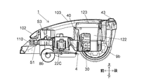
- FIG. 3 is a cross-sectional view taken along the line AA in FIG. 2 (a vertical cross-sectional view passing through the center position of the self-propelled lawn mower 1).
- the self-propelled lawn mower 1 is driven by small-diameter front wheels 8a and 8b that are capable of turning or swinging along the traveling direction and independent traveling wheel motors (left wheel motor 22A and right wheel motor 22B).
- the control unit 15 such as a microcomputer mounted on the main board 40 (FIG. 2) drives the left wheel motor 22A and the right wheel motor 22B shown in FIG. 2 and the cutting blade motor 22C shown in FIG.
- the controlled lawn mower 1 cuts grass while traveling autonomously.
- an openable / closable cover 103 is provided above the main body cover 102.
- the dial knob, the keyboard 124, and the display 125 shown in FIG. A substantially rectangular opening 105 is provided in front of the main body cover 102 when viewed from the front, and two DC output terminals 51 and 52 of the charging base 50 shown in FIG.
- the charging terminals 10a and 10b of the self-propelled lawn mower 1 can be contacted.
- the front end portion of the main body chassis 110 is located inside the opening 105, and charging terminals 10a and 10b are provided on the slopes of the left and right side surfaces thereof.
- a stop button 43 for manual stop is provided on the upper rear side of the main body cover 102.
- the left wheel motor 22A and the right wheel motor 22B are capable of steering control by the control unit 15 (including a microcomputer) mounted on the main board 40 by being driven synchronously or asynchronously.
- the self-propelled lawn mower 1 goes straight or reverse by driving the rear wheels 9a and 9b synchronously, and is self-propelled in a predetermined direction by driving so as to generate a rotational difference between the rear wheels 9a and 9b.
- the lawn mower 1 can be turned.
- the left wheel motor 22A and the right wheel motor 22B are, for example, brushless DC motors, and are driven via the left wheel driver 18 and the right wheel driver 19 of FIG.
- a container part 122 that houses the storage battery 30 and houses the main board 40 on which the microcomputer is mounted is provided on the rear side of the main body chassis 110, and the opening of the container part 122 can be opened and closed. Covered by the portion 123.
- a display 125 such as a liquid crystal display panel, a keyboard 124, and a main switch SW1 are provided on the upper surface of the lid 123. The operator can set the mowing schedule by operating the keyboard 124.
- the main body cover 102 is held in a floating state with respect to the main body chassis 110 by a spring or the like, so that the main body cover 102 can move slightly in the front / rear, left / right, and up / down directions.
- the control unit 15 described later detects a collision of the self-propelled lawn mower 1 with an obstacle.
- a rotary type cutting blade 4 that rotates at a predetermined distance parallel to the ground, and a driving device for rotating the cutting blade 4.
- a cutting blade motor 22C is provided on the lower side near the center of the main body chassis 110.
- the cutting blade motor 22C is, for example, a brushless DC motor, and a rotor core (not shown) having a permanent magnet rotates inside a stator (not shown) around which an exciting coil is wound.
- a circular inverter circuit board (not shown) is provided on the upper end side of the cutting blade motor 22C, and there are a plurality of Hall ICs (not shown), FETs (field effect transistors) and IGBTs (insulated gate bipolar transistors). A plurality of switching elements are mounted.
- a substantially rectangular parallelepiped container portion 122 for housing the storage battery 30, the main substrate, and the like is provided on the rear side of the cutting blade motor 22C.
- the container part 122 is manufactured by integral molding with the plate-like base part 121 using a synthetic resin such as plastic, and can be opened and closed by the lid part 123.
- a first guide wire sensor S1 is provided near the front end of the main body chassis 110.
- the first guide wire sensor S1 converts a change in the surrounding magnetic field into a change in current by a coil.
- a second guide wire sensor S ⁇ b> 2 is provided near the rear end of the main body chassis 110.
- FIG. 4 is an explanatory diagram of the usage environment of the self-propelled lawn mower 1.
- FIG. 5 is a schematic diagram showing the self-propelled lawn mower 1, the charging base 50, and the AC adapter 60.
- the self-propelled lawn mower 1 includes a main body 2 having front wheels 8a and 8b, rear wheels 9a and 9b, and a cutting blade 4, and a storage battery (battery pack) 30 that is detachably attached to the battery pack mounting portion 5 of the main body 2. Is provided.
- the self-propelled lawn mower 1 is operated by the electric power of the storage battery 30, and when the remaining capacity of the storage battery 30 decreases, the self-propelled lawn mower 1 self-travels to the charging base 50 and charges the storage battery 30.
- the storage battery 30 that can be attached to and detached from the self-propelled lawn mower 1 can preferably be shared with other types of electric working machines.
- FIG. 6 shows a state in which the storage battery 30 is attached to the hedge trimmer 7.
- a guide wire (guidance wire) 80 shown in FIG. 4 is connected to the charging base 50 and is disposed (for example, embedded) in order to partition (regulate) a traveling area of the self-propelled lawn mower 1, that is, a lawn mowing area. )
- the guide wire 80 surrounds the lawn mowing area including the charging base 50, and the self-propelled lawn mower 1 is premised on automatically traveling inside the area surrounded by the guide wire 80.
- the charging base 50 is installed at a corner of the lawn mowing area, and is connected to the AC adapter 60 by a cable 70.
- the AC adapter 60 is connected to an external AC power supply 90 such as a commercial AC power supply, and converts an AC voltage (for example, 100 V) supplied from the external AC power supply 90 into a DC voltage (for example, 21 V).
- the DC voltage output from the AC adapter 60 is transmitted to the charging base 50 through the cable 70 and is output between the two DC output terminals 51 and 52 of the charging base 50.
- the output voltage of the charging base 50 is preferably 25 V or less, so that the circuit components of the self-propelled lawn mower 1 that receives the output voltage of the charging base 50 can be made inexpensive with a withstand voltage of 25 V or less. .
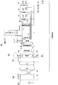
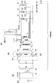
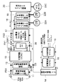
- FIG. 7 is a block diagram of the self-propelled lawn mower 1, the charging base 50, and the AC adapter 60 in an interconnected state.
- the AC adapter 60 transforms, for example, AC 100V input from the external AC power source 90 by the transformer 61, rectifies the output voltage of the transformer 61 by the diode bridge 62 (for example, full-wave rectification), and converts the output voltage of the diode bridge 62 to the capacitor C. To output, for example, DC21V.
- the cable 70 has one end detachably attached to the output terminal of the AC adapter 60, and the other end detachable from the input terminal of the charging base 50, and transmits the DC voltage output from the AC adapter 60 to the charging base 50.
- the charging base 50 includes a control unit (microcomputer) 53.
- the control unit 53 operates with an input voltage from the cable 70 and causes a current to flow through the guide wire 80.
- the self-propelled lawn mower 1 detects a magnetic field generated by a current flowing through the guide wire 80 by a guide wire sensor (not shown) (for example, a magnetic detection means such as a coil disposed in front of and behind the main body 2), and a lawn mowing area is detected. recognize.
- the control unit 53 operates a later-described discriminated circuit 11 of the self-propelled lawn mower 1 to detect that the main body 2 of the self-propelled lawn mower 1 is connected to the DC output terminals 51 and 52.
- the self-propelled lawn mower 1 has charging terminals 10 a and 10 b in the main body 2 that can be connected to and disconnected from the DC output terminals 51 and 52 of the charging base 50.
- DC21V input to the charging terminals 10a and 10b from the charging base 50 is supplied to the circuit to be discriminated 11 and the charging circuit (buck-boost circuit) 13, and is also supplied to the control power supply circuit 14 through the backflow prevention diode D1.
- the control power supply circuit 14 is also supplied with an output voltage (for example, DC 18 V) of a drive power supply circuit 17 to be described later through a backflow prevention diode D2.
- the to-be-determined circuit 11 is provided to allow the charging base 50 to determine that the main body 2 of the self-propelled lawn mower 1 is connected to the charging base 50, and does not operate with the power of the storage battery 30. In addition, the operation is performed by supplying power from the charging base 50, and even when the discharge of the storage battery 30 progresses and so-called battery runs out (remaining capacity is substantially zero), the charging base 50 side can make a determination.
- the determined circuit 11 is a predetermined CR time constant circuit, for example. When the DC output terminals 51 and 52 of the charging base 50 are short-circuited, the control unit 53 of the charging base 50 does not recognize that the main body 2 of the self-propelled lawn mower 1 is connected, and the charging base 50 50 operations can be stopped.
- the control power supply circuit 14 inputs DC21V between the charging terminals 10a and 10b or DC18V output from the drive power supply circuit 17 described later, and supplies DC5V to the control unit (microcomputer) 15. Specifically, DC -DC converter (voltage conversion means). Even when the storage battery 30 runs out of power, power is supplied from the charging base 50 to the control power supply circuit 14 when connected to the charging base 50, and the control unit 15 can execute control for charging. That is, when the storage battery 30 runs out of power, power supply via the storage battery 30 (power supply from the drive power supply circuit 17) to the control power supply circuit 14 is eliminated to reduce power consumption to zero. In addition, when connected to the charging base 50, the control by the control unit 15 for charging can be performed without any trouble.
- the control unit 15 monitors the output voltage of the control power supply circuit 14, determines whether the self-propelled lawn mower 1 and the charging base 50 are connected, and whether the voltage supplied from the charging base 50 is normal. Make a decision.
- the control unit 15 also performs battery voltage identification (T), battery temperature monitoring / overcharge monitoring (LS), overdischarge monitoring (LD), charging current monitoring, and battery voltage monitoring. Stop charging.
- the charging circuit 13 boosts or steps down the DC 21V between the charging terminals 10a and 10b according to the rated output voltage of the storage battery 30 and charges the storage battery 30 with a charging voltage that matches the rated output voltage of the storage battery 30 ( Voltage conversion means). Note that the step-down by the charging circuit 13 is performed when, for example, when the rated output voltage of the storage battery 30 is 18V and consumption is severe, it is desired to charge slowly, or when a storage battery lower than 18V can be used and, for example, it is desired to charge a storage battery of 14V. Is called.
- the storage battery 30 is attached to the battery pack mounting portion 5 of the main body 2 shown in FIG.
- each terminal of the storage battery 30 (+ terminal, ⁇ terminal, C + terminal, 5V terminal, LD terminal, T terminal, LS shown in FIG. 7) Terminal
- the control unit 15 receives an identification signal of the type (rated output voltage, etc.) of the storage battery 30 from the T terminal, and controls the charging circuit 13 to perform a charging operation with a voltage that matches the rated output voltage of the mounted storage battery 30. To do. Identification of the type of the storage battery 30 by the control unit 15 is performed every time the storage battery 30 is mounted or each time the charging base 50 and the main body 2 are connected.
- the case where the rated output voltage of the storage battery 30 is two types of 36V and 18V is assumed.
- the charging circuit 13 boosts and outputs DC 21 V between the charging terminals 10 a and 10 b to a DC voltage slightly higher than 36 V.
- the charging circuit 13 steps down and outputs the DC 21V between the charging terminals 10a and 10b to a DC voltage slightly higher than 18V.
- the drive power supply circuit 17 is a DC-DC converter capable of at least stepping down, and converts the output voltage of the storage battery 30 into a stable DC voltage of 18V and outputs it.
- the output voltage of the drive power supply circuit 17 is supplied to the control power supply circuit 14 via the backflow prevention diode D2, and the left wheel driver (left wheel motor driver circuit) 18, right wheel driver (right wheel motor driver circuit). 19 and a cutting blade driver (cutting blade motor driver circuit) 20 are respectively supplied.
- the left wheel driver 18 supplies power to the left wheel motor 22A that rotationally drives the left rear wheel 9a by, for example, PWM control.
- the right wheel driver 19 supplies power to the right wheel motor 22B that rotationally drives the right rear wheel 9b by, for example, PWM control.
- the cutting blade driver 20 supplies power to the cutting blade motor 22C that drives the cutting blade 4 by, for example, PWM control.
- the left wheel motor 22A, the right wheel motor 22B, and the cutting blade motor 22C are preferably brushless motors.
- the left wheel driver 18, the right wheel driver 19, and the cutting blade driver 20 are controlled by the control unit 15.
- each driver has a plurality of switching elements, and each switching element is PWM-controlled by the control unit 15, for example.
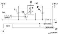
- FIG. 8 is a circuit diagram showing a specific configuration example of the charging circuit 13 of FIG.
- the charging circuit 13 as a power supply unit includes an insulating transformer 91, a MOSFET 92 that is a switching element, capacitors 93 and 94, a diode 95, a switching control circuit 96, a current control circuit 97, a voltage control circuit 99, and a current detection circuit (not shown). Including a voltage detection circuit.
- the MOSFET 92 is driven by the PWM signal from the control unit 15 via the switching control circuit 96 and performs a switching operation, a charging voltage is generated on the output terminal side.
- the control unit 15 identifies the voltage of the storage battery 30, and provides the current control circuit 97 and the voltage control circuit 99 with current and voltage settings corresponding thereto.
- the control circuit 15 outputs an ON signal for starting the operation of the switching control circuit 96.
- the switching control circuit 96 modulates the pulse width based on the feedback signal output from the current control circuit 97 and the voltage control circuit 99 and drives the MOSFET 92.
- the MOSFET 92 When the MOSFET 92 is stopped, no voltage is output to the output terminal side.
- the control unit 15 charges the storage battery 30 with a constant current until the battery voltage reaches a predetermined voltage, and after that reaches the predetermined voltage, charges the storage battery 30 with a constant voltage. Feedback control is performed so as to maintain a constant voltage while gradually decreasing.
- the control unit 15 determines that the charging is completed when the charging current is reduced to a predetermined value, and stops the switching operation (PWM control) of the MOSFET 92.
- FIG. 9 is a block diagram showing various functional parts and their interconnection relationship in the self-propelled lawn mower 1.
- a circuit portion excluding the motor of FIG. 7 is mounted on the main board 40, and is attached to the DC output terminals 51, 52 of the charging base 50, the detachable charging terminals 10 a, 10 b, and the battery mounting portion 5.
- the battery connection terminals 42a and 42b terminals that are not shown but are connected to the identification terminals) that are detachably connected to the terminals (output voltage terminal and identification terminal) of the storage battery 30 are connected to the main board 40. .
- the main switch SW1 is inserted into the connection lines of the battery connection terminals 42a and 42b and the main board 40, and is a power supply switch to the main board 40 and the motor of the self-propelled lawn mower 1.
- the main board 40 is connected to a left wheel motor 22A, a right wheel motor 22B, and a cutting blade motor 22C, as well as first and second guide wire sensors S1, S2, a lift sensor S3, an inclination sensor S4, and a stop button. 43, a display keyboard substrate 44 is connected.
- the first and second guide wire sensors S1 and S2 are coils disposed, for example, before and after the main body 2, and receive an AC electrical signal from the guide wire 80 and output it to the main board 40.
- the control unit 15 mounted on the main board 40 recognizes the boundary of the lawn mowing area, and controls the direction of the self-propelled lawn mower 1 through the left wheel driver 18 and the left wheel driver 19. This is executed by controlling the rotational direction and the rotational speed of 22A and the right wheel motor 22B.
- the lift sensor S3 detects this and outputs it to the main board 40.
- the control unit 15 stops the left wheel motor 22A, the right wheel motor 22B, and the cutting blade motor 22C.
- the inclination sensor S4 detects when the self-propelled lawn mower 1 is inclined at a predetermined angle or more with respect to the ground and outputs it to the main board 40 so as not to enter the inclined surface.
- the control of the motor 22A and the right wheel motor 22B is changed to change the traveling direction, and the inclination sensor S4 tries to return to the normal value.
- the control unit 15 When the control unit 15 further detects that the tilt sensor S4 exceeds the threshold value equal to or greater than the predetermined angle, the control unit 15 stops the left wheel motor 22A, the right wheel motor 22B, and the cutting blade motor 22C.
- the stop button 43 is a manual stop means, and stops the self-propelled lawn mower 1 during automatic traveling or lawn mowing by manual operation.
- the display keyboard board 44 is an input device for information on lawn mowing, and is arranged on the outer surface of the main body 2 so that an operator can perform manual operation, and sets an operation start instruction, a timer setting, a work area, and the like. . Note that power is supplied to the sensors S1 to S4, the display keyboard board 44, and the like from the control system power supply 14.
- the charging base 50 discriminates the discriminated circuit 11 and supplies a DC voltage of 21 V to the main body 2.
- the charging circuit 13 charges the storage battery 30 with a DC voltage that matches the rated output voltage (36 V or 18 V) of the storage battery 30 in accordance with a command from the control unit 15 that has identified the rated output voltage of the storage battery 30.
- the self-propelled lawn mower 1 After the charging is completed, the self-propelled lawn mower 1 is detached from the charging base 50 and performs an automatic traveling operation and a lawn mowing operation that are predetermined by the control unit 15. The self-propelled lawn mower 1 returns to the charging base 50 when the requested lawn mowing operation ends or when the remaining capacity of the storage battery 30 decreases.
- the threshold value for determining that the remaining capacity of the storage battery 30 has decreased is changed according to the rated output voltage of the connected storage battery 30 (for example, a predetermined ratio to the rated output voltage).
- the control unit 15 determines that the remaining capacity has decreased at a higher voltage than when the rated output voltage of the storage battery 30 is 18 V, and performs the feedback operation to the charging base 50. Start.
- the self-propelled lawn mower 1 has a charging circuit 13 as a charging circuit in the main body 2, and converts the supply voltage from the charging base 50 into a DC voltage corresponding to the rated output voltage of the storage battery 30 by the charging circuit 13. Then, since the storage battery 30 is charged, the storage battery 30 having a rated output voltage of 36V can be surely fully charged.
- the self-propelled lawn mower 1 requires a detachable part in the secondary circuit, and the DC output voltage from the charging base 50 is preferably 42 V or less, for example, but the main body 2 is charged in this embodiment.
- the output voltage of the charging base 50 can take a large margin with respect to 42 V, which is advantageous in design, and the circuit of the self-propelled lawn mower 1 to which the output voltage of the charging base 50 is applied.
- the parts can be made into inexpensive parts with low withstand pressure, and the cost is low.
- DC5V as a power source for the control unit 15 can be created by a single-stage power circuit (control power circuit 14). Therefore, the number of parts can be reduced compared to the case where a power supply circuit having two or more stages is required to create DC5V.
- the AC adapter 60 is advantageous in terms of cost reduction because it may be highly versatile with an output voltage of about DC 21V.
- the storage battery 30 Since the storage battery 30 is charged by the battery charging circuit 13, the storage battery 30 having a plurality of types of rated output voltages can be charged.
- the traveling lawn mower 1 has a structure in which the storage battery 30 is detachably attached to the main body 2. When the remaining capacity of the storage battery 30 decreases, the lawn mower can be continued by replacing it with a charged storage battery. It is.
- the supply voltage from the storage battery 30 is converted into a drive voltage of, for example, 18 V by the drive power supply circuit 17 and supplied to the left wheel driver 18, right wheel driver 19, and cutting blade driver 20, so that the left wheel driver 18, right
- the storage battery 30 having a plurality of types of rated output voltages can be used without changing the control of the wheel driver 19 and the blade driver 20.
- each switching element Since the self-propelled lawn mower 1 uses a plurality of motors, a large number of switching elements are required for driving the motor, and if each switching element is an element having a high withstand voltage capable of supporting 36V, the cost becomes high.
- each switching element by converting the output voltage of the storage battery 30 into a drive voltage of 18V and supplying it to each driver, each switching element can be made an inexpensive element with a low withstand voltage, Cost is low.
- the charging base 50 can recognize that the self-propelled lawn mower 1 is connected, and it is unforeseen such as a short circuit between the DC output terminals 51 and 52. Can determine the situation.
- the charging circuit 13 is an insulation type in which the input side and the output side are insulated from each other by a transformer, and since a DC voltage is input, no voltage change occurs in the transformer when the MOSFET 92 is short-circuited. Since it does not function, no voltage is output to the output terminal side, and the storage battery 30 is not charged even if the storage battery 30 is connected to the output terminal at the time of a short circuit failure. Therefore, it is possible to prevent an unintended high voltage from being applied to the storage battery 30 at the time of a short circuit failure and the storage battery 30 from being overcharged.
- FIG. 10 is a block diagram according to the second embodiment of the present invention, in which the input method of the control power supply circuit 14 is changed as compared with FIG.
- the output voltage of the storage battery 30 is supplied to the control power supply circuit 14 through the backflow prevention diode D2.
- Other points in FIG. 10 are the same as those in FIG.
- inexpensive circuit components having a low withstand voltage cannot be used for the control power supply circuit 14, but the same effects as the configuration shown in FIG. 7 can be obtained in other respects.
- FIG. 11 is a block diagram according to the third embodiment of the present invention, in which the drive power supply circuit 17 is omitted as compared with FIG.
- the output voltage of the storage battery 30 is directly supplied to the left wheel driver 18, the right wheel driver 19, and the cutting blade driver 20.
- the rated output voltage of the storage battery 30 changes, it responds by changing the duty of PWM control of each driver.
- each driver supplies power to each motor by PWM control with a duty of about 100% when the rated output voltage of the storage battery 30 is 18V, and the duty is about 50 when the rated output voltage of the storage battery 30 is 36V.
- each motor By supplying electric power to each motor with% PWM control, each motor is driven under substantially the same output condition regardless of the rated output voltage of the storage battery 30.
- Other points in FIG. 11 are the same as those in FIG. In the case of the configuration of FIG. 11, the same effects as the configuration shown in FIG. 10 can be obtained except for the low-speed rotation control and the withstand voltage of the switching elements of the drivers.
- FIG. 12 is a circuit block diagram of a self-propelled lawn mower according to Embodiment 4 of the present invention.
- a DC voltage of 41.5 V is input to the charging terminals 10a and 10b from the charging base.
- a DC voltage of 41.5 V between the charging terminals 10a and 10b is supplied to the determination target circuit 11, the charging circuit control power source 12, and the charging circuit 13 via the fuse FS1.
- the charging circuit control power supply 12 steps down DC41.5V to DC18V and supplies it to the control power supply circuit 14 through the backflow prevention diode D1, and is specifically constituted by a DC-DC converter (voltage conversion means). Is done.
- the control power supply circuit 14 is also supplied with a voltage of DC18V from a drive power supply circuit (18V power supply) 17 described later via a backflow prevention diode D 2.
- the control power supply circuit 14 supplies a DC voltage of 5V to the charge control microcomputer (microcomputer) 15A and the main body control microcomputer 15B, and is specifically a DC-DC converter (voltage conversion means).
- the charging control microcomputer 15A and the main body control microcomputer 15B correspond to the control unit 15 in FIG.
- the power supply 12 for charging circuit control enables power supply to the control power supply circuit 14 when connected to the charging base 50 even when the storage battery 30 runs out of battery, and enables control for charging. . That is, when the storage battery 30 runs out of power, the power supply via the storage battery 30 to the control power supply circuit 14 is eliminated to reduce power consumption to zero, but the charging base 50 is provided by providing the charging circuit control power supply 12.
- the control by the charging control microcomputer 15A for charging at the time of connection to can be performed without any trouble.
- the charging circuit 13 functions as a step-down unit (may be a step-up unit depending on the rated output voltage of the storage battery 30), and conforms to the rated output voltage of the storage battery 30 via the backflow prevention diode D3 and the relay RY1. It is a DC-DC converter (voltage conversion means) that charges the storage battery 30 with a charging voltage to be applied.
- each terminal of the storage battery 30 is connected to the battery connection terminals 42 a and 42 b provided on the storage battery mounting portion 5 (not shown, but identification of the storage battery 30 is performed). There is also a terminal for receiving signals).
- the charging control microcomputer 15A receives an identification signal of the type (rated output voltage, etc.) of the storage battery 30, and the charging control microcomputer 15A performs the charging operation with the charging circuit 13 at a voltage that matches the rated output voltage of the mounted storage battery 30. To control.
- the type of the storage battery 30 is identified by the charging control microcomputer 15A every time the storage battery 30 is attached or every time the charging base 50 and the main body 2 are connected. Since the self-propelled lawn mower 1 consumes a large amount of power and the DC-DC converter of the charging circuit 13 cannot operate the load, the load side of the storage battery 30 should be disconnected during charging by the relay RY1. Yes.
- the drive power supply circuit 17 and the blade motor driver circuit 20 are connected to the storage battery 30 via the relay RY1 when charging is completed.
- the drive power supply circuit 17 is composed of a DC-DC converter, and creates a DC voltage of 18V for a wheel motor and other control circuits. That is, 18V DC voltage is supplied to the control power supply circuit 14 via the backflow prevention diode D2, and 18V DC voltage is supplied to the left wheel driver 18 and the left wheel driver 19.
- the cutting blade motor driver circuit 20 supplies power to the cutting blade motor 22C that drives the cutting blade 4 by PWM control.
- the cutting blade motor driver circuit 20 supplies power to the cutting blade motor 22C by PWM control with a duty of 100% when the rated output voltage of the storage battery 30 is 18V, and the duty is about 50% when the rated output voltage of the storage battery 30 is 36V.
- PWM control power is supplied to the cutting blade motor 22C, so that the cutting blade motor 22C can be driven under substantially the same output condition regardless of the rated output voltage of the storage battery 30.
- the left wheel driver 18 supplies power to the left wheel motor 22A that rotationally drives the left rear wheel 9a by PWM control
- the left wheel driver 19 supplies power to the right wheel motor 22B that rotationally drives the right rear wheel 9b by PWM control.
- These motor driver circuits 18, 19, and 20 are controlled by the main body control microcomputer 15B.
- a main switch SW1 and a fuse FS2 are inserted in series between the storage battery 30 and the drive power supply circuit 17 and the blade motor driver circuit 20 on the load side.
- the charging circuit control power supply 12 supplies a DC voltage of 18V to the control power supply circuit 14, and the control power supply circuit 14 supplies a DC voltage of 5V to the charge control microcomputer 15A and the main body control microcomputer 15B.
- the various controls are made possible.
- the charging circuit 13 When the charging circuit 13 is in an operating state, the storage battery 30 is connected to the output side of the charging circuit 13 by the relay RY1, and the charging circuit 13 determines the rated output voltage of the storage battery 30 (in accordance with a command from the charging control microcomputer 15A that identifies the rated output voltage of the storage battery 30).
- the storage battery 30 is charged with a DC voltage suitable for 36V or 18V).
- the charging circuit 13 switches the relay RY1 to the load side (the power supply side to the motor or the like), that is, the side connecting to the drive power supply circuit 17 and the cutting blade motor driver circuit 20.
- a semiconductor switch means may be used instead of the relay RY1 for switching the connection destination of the storage battery 30 from the charging circuit 13 to the drive power supply circuit 17 and the motor driver circuits 18, 19, 20 side.
- a semiconductor switch means may be used instead of the relay RY1 for switching the connection destination of the storage battery 30 from the charging circuit 13 to the drive power supply circuit 17 and the motor driver circuits 18, 19, 20 side.
- you may supply electric power to a left wheel motor, a right wheel motor, and a cutting blade motor via the pressure
- the charging base 50 may incorporate a function of the AC adapter 60 (a function of converting an AC voltage into a DC voltage).
- the charging circuit 13 is a step-up / step-down circuit.
- the charging circuit 13 has at least a boosting function. That's fine.
- the self-propelled lawn mower 1 may alternatively be equipped with three or more types of storage batteries having different rated output voltages.
- the specific numerical values exemplified in the embodiment, for example, the rated output voltage of the storage battery 30, the output voltage of the charging base 50, and the upper limit value thereof are merely examples for explanation, and are appropriately set according to the actual use environment. Is.
- right wheel driver (right wheel motor driver circuit), 20 ... cutting Blade driver (cutting blade motor driver circuit), 22A ... left wheel motor, 22B ... right wheel motor, 22C ... cutting blade motor, 30 ... storage battery, 40 ... main board, 42a, 42b ... battery connection terminal, 43 Stop button, 44 ... Display keyboard, 50 ... Charging base, 51, 52 ... DC output terminal (power transmission terminal), 53 ... Control unit (microcomputer), 60 ... AC adapter, 61 ... Transformer, 62 ... Diode bridge, 70 ... Cable , 80 ... Guide wire (induction wire), 90 ... External AC power supply, 91 ... Transformer, 92 ... MOSFET, 93, 94 ... Capacitor, diode 95, 102 ...
- Body cover 102a, 102b ... Fender, 102c ... Front lower end, 103 ... Opening and closing cover, 105 ... Opening part, 110 ... Main body chassis, 119a, 119b ... Magnet, 121 ... Base part, 122 ... Container part, 123 ... Cover part, 124 ... Keyboard, 125 ... Display, 137 ... Stop switch, C ... Capacitors, D1, D2 ... Backflow prevention diodes, S1 S2 ... guide wire sensor, S3 ... lift sensor, S4 ... tilt sensor
Landscapes
- Life Sciences & Earth Sciences (AREA)
- Environmental Sciences (AREA)
- Harvester Elements (AREA)
- Charge And Discharge Circuits For Batteries Or The Like (AREA)
- Electric Propulsion And Braking For Vehicles (AREA)
Abstract
Description
前記蓄電池の前記帰還動作を開始する電圧を前記定格出力電圧に応じて変更可能であるとよい。
図1~図9を参照し、本発明の実施の形態1を説明する。図1は、本発明の実施の形態1に係る自走式芝刈機1の斜視図である。図2は、自走式芝刈機1の、本体カバー102を外した状態の上面図である。図3は、図2のA-A断面図(自走式芝刈機1の左右中心位置を通る鉛直断面図)である。自走式芝刈機1は、走行方向に沿って転回または揺動可能に設けられる小径の前輪8a,8bと、独立した走行用の車輪モータ(左車輪モータ22A及び右車輪モータ22B)で駆動される駆動輪である大径の後輪9a,9bを左右にそれぞれ有する。自走式芝刈機1は、本体カバー102によって上部全体が覆われる。自走式芝刈機1の電源は、着脱可能な蓄電池30(図4及び図5)である。メイン基板40(図2)に搭載されたマイクロコンピュータ等の制御部15(図7)によって、図2に示す左車輪モータ22A及び右車輪モータ22B、並びに図3に示す刈刃モータ22Cの駆動が制御され、自走式芝刈機1は自律的に走行しながら草を刈り取る。
図10は、本発明の実施の形態2であって、図7と比較して制御用電源回路14の入力の取り方を変更したブロック図である。図10の例では、蓄電池30の出力電圧が、逆流防止用ダイオードD2を通して制御用電源回路14に供給される。図10におけるその他の点は図7と共通である。図10の構成の場合、制御用電源回路14には耐圧の低い安価な回路部品を使用できないが、その他の点では図7に示した構成と同様の効果を奏することができる。
図11は、本発明の実施の形態3であって、図10と比較して駆動電源回路17を省略したブロック図である。図11の例では、蓄電池30の出力電圧が、左車輪ドライバ18、右車輪ドライバ19、及び刈刃ドライバ20にそれぞれ直接供給される。蓄電池30の定格出力電圧が変わった場合には、各ドライバのPWM制御のデューティを変更することで対応する。具体的には、各ドライバは、蓄電池30の定格出力電圧が18Vのときはデューティ約100%のPWM制御で各モータに電力供給を行い、蓄電池30の定格出力電圧が36Vのときはデューティ約50%のPWM制御で各モータに電力供給を行うことで、蓄電池30の定格出力電圧にかかわらず各モータを実質的に同じ出力条件で駆動する。図11におけるその他の点は図10と共通である。図11の構成の場合、低速回転制御や各ドライバのスイッチング素子の耐圧の点を除けば、図10に示した構成と同様の効果を奏することができる。
図12は、本発明の実施の形態4に係る自走式芝刈機の回路ブロック図である。以下、図7に示す実施の形態1との相違点を中心に説明する。充電端子10a,10bには、充電ベースから41.5Vの直流電圧が入力される。充電端子10a,10b間の41.5Vの直流電圧は、ヒューズFS1を介して被判別回路11、充電回路制御用電源12及び充電回路13に供給される。
Claims (17)
- 蓄電池の電力によってモータを駆動して動作する自走式芝刈機であって、直流電圧を供給する充電ベースに対して接続、離脱可能な充電端子と、前記充電端子から入力された直流電圧を変圧して出力可能な充電回路とを備え、前記充電回路の出力電圧により前記蓄電池を充電可能であることを特徴とする自走式芝刈機。
- 前記充電回路は、前記充電端子から入力された直流電圧を昇圧可能であることを特徴とする請求項1に記載の自走式芝刈機。
- 前記充電回路は、トランスにより入力側と出力側が相互に絶縁された絶縁型であることを特徴とする請求項1又は2に記載の自走式芝刈機。
- 前記蓄電池の充電時には、前記蓄電池を前記モータへの電力供給経路から切り離すことを特徴とする請求項1から3のいずれか一項に記載の自走式芝刈機。
- 前記充電ベースの出力電圧が25V以下である、請求項1から4のいずれか一項に記載の自走式芝刈機。
- 前記蓄電池が着脱可能であることを特徴とする請求項1から5のいずれか一項に記載の自走式芝刈機。
- 前記蓄電池が他の種類の電動作業機でも共用可能であることを特徴とする請求項6に記載の自走式芝刈機。
- 相互に定格出力電圧の異なる複数種類の蓄電池を択一的に装着可能であることを特徴とする請求項6又は7に記載の自走式芝刈機。
- 充電回路は、接続された蓄電池の定格出力電圧を識別して、前記定格出力電圧に対応する直流電圧で充電することを特徴とする請求項8に記載の自走式芝刈機。
- 前記蓄電池の電圧の低下を判断して前記充電ベースへの帰還動作が開始され、
前記蓄電池の前記帰還動作を開始する電圧を前記定格出力電圧に応じて変更可能であることを特徴とする請求項8又は9に記載の自走式芝刈機。 - 前記蓄電池の出力電圧を変圧して出力可能な駆動用電源回路を備え、前記駆動用電源回路の出力電圧を利用して前記モータを駆動することを特徴とする請求項1から10のいずれか一項に記載の自走式芝刈機。
- 前記駆動用電源回路は、前記蓄電池の出力電圧を降圧可能であることを特徴とする請求項11に記載の自走式芝刈機。
- 前記駆動用電源回路がDC-DCコンバータであることを特徴とする請求項11又は12に記載の自走式芝刈機。
- 前記駆動用電源回路が実効電圧を制御するモータドライバ回路であることを特徴とする請求項11から13のいずれか一項に記載の自走式芝刈機。
- 制御部と、前記制御部に電源を供給する制御用電源回路とを備え、前記制御用電源回路の入力端子に、前記駆動用電源回路の出力電圧、及び前記充電端子からの直流電圧が、択一的に入力される、請求項11から14のいずれか一項に記載の自走式芝刈機。
- 前記モータが、刈刃を駆動する刈刃モータと、左車輪を駆動する左車輪モータと、右車輪を駆動する右車輪モータとを含む、請求項1から15のいずれか一項に記載の自走式芝刈機。
- 前記モータがブラシレスモータである、請求項1から16のいずれか一項に記載の自走式芝刈機。
Priority Applications (3)
| Application Number | Priority Date | Filing Date | Title |
|---|---|---|---|
| CN201590001237.XU CN207075240U (zh) | 2014-12-26 | 2015-12-11 | 自行式割草机 |
| DE212015000289.6U DE212015000289U1 (de) | 2014-12-26 | 2015-12-11 | Selbstfahrender Rasenmäher |
| JP2016566110A JPWO2016104187A1 (ja) | 2014-12-26 | 2015-12-11 | 自走式芝刈機 |
Applications Claiming Priority (4)
| Application Number | Priority Date | Filing Date | Title |
|---|---|---|---|
| JP2014-266745 | 2014-12-26 | ||
| JP2014266745 | 2014-12-26 | ||
| JP2015-110492 | 2015-05-29 | ||
| JP2015110492 | 2015-05-29 |
Publications (1)
| Publication Number | Publication Date |
|---|---|
| WO2016104187A1 true WO2016104187A1 (ja) | 2016-06-30 |
Family
ID=56150217
Family Applications (1)
| Application Number | Title | Priority Date | Filing Date |
|---|---|---|---|
| PCT/JP2015/084800 Ceased WO2016104187A1 (ja) | 2014-12-26 | 2015-12-11 | 自走式芝刈機 |
Country Status (4)
| Country | Link |
|---|---|
| JP (1) | JPWO2016104187A1 (ja) |
| CN (1) | CN207075240U (ja) |
| DE (1) | DE212015000289U1 (ja) |
| WO (1) | WO2016104187A1 (ja) |
Cited By (8)
| Publication number | Priority date | Publication date | Assignee | Title |
|---|---|---|---|---|
| JP2018014963A (ja) * | 2016-07-29 | 2018-02-01 | 日立工機株式会社 | 自走式作業機 |
| JP2018082682A (ja) * | 2016-11-25 | 2018-05-31 | 本田技研工業株式会社 | 作業機 |
| JP2018082684A (ja) * | 2016-11-25 | 2018-05-31 | 本田技研工業株式会社 | 作業機 |
| WO2018116721A1 (ja) * | 2016-12-20 | 2018-06-28 | 株式会社 マキタ | ロボットポリッシャ |
| JPWO2021130939A1 (ja) * | 2019-12-25 | 2021-07-01 | ||
| US20220171402A1 (en) * | 2019-03-28 | 2022-06-02 | Honda Motor Co., Ltd. | Autonomous travel working machine and charging station |
| US11592819B2 (en) * | 2016-11-29 | 2023-02-28 | Briggs & Stratton, Llc | Robotic lawn mower including removable rechargeable battery module |
| US12472839B2 (en) | 2019-10-11 | 2025-11-18 | Ariens Co. | Power source and control system for a lawn mower |
Families Citing this family (13)
| Publication number | Priority date | Publication date | Assignee | Title |
|---|---|---|---|---|
| US12342761B2 (en) | 2017-12-28 | 2025-07-01 | Nanjing Chervon Industry Co., Ltd. | Outdoor moving device |
| WO2019129045A1 (zh) | 2017-12-28 | 2019-07-04 | 南京德朔实业有限公司 | 骑乘式电动割草机 |
| CN110651590A (zh) * | 2018-06-29 | 2020-01-07 | 南京德朔实业有限公司 | 割草机 |
| SE543724C2 (en) * | 2018-10-24 | 2021-06-29 | Husqvarna Ab | Articulated robotic working tool with goniometer arrangement |
| DE102019201143A1 (de) * | 2019-01-30 | 2020-07-30 | Robert Bosch Gmbh | Autonomes Arbeitsgerät |
| CN110506488A (zh) * | 2019-09-19 | 2019-11-29 | 常州格力博有限公司 | 多功能智能设备 |
| CN218998877U (zh) | 2021-06-25 | 2023-05-12 | 南京泉峰科技有限公司 | 骑乘式割草机 |
| CN115622208A (zh) * | 2021-07-12 | 2023-01-17 | 南京泉峰科技有限公司 | 自驱动设备系统及其充电站 |
| CN115868303A (zh) | 2021-09-29 | 2023-03-31 | 创科无线普通合伙 | 机器人园林工具系统及用于机器人园林工具的方法 |
| FR3143263A1 (fr) * | 2022-12-16 | 2024-06-21 | Valeo Embrayages | Tondeuse à gazon électrique |
| WO2024126110A1 (fr) * | 2022-12-16 | 2024-06-20 | Valeo Embrayages | Tondeuse à gazon électrique |
| FR3143262A1 (fr) * | 2022-12-16 | 2024-06-21 | Valeo Embrayages | Tondeuse à gazon électrique |
| WO2025259869A1 (en) * | 2024-06-12 | 2025-12-18 | Husqvarna Ab | Multi-purpose charging port |
Citations (10)
| Publication number | Priority date | Publication date | Assignee | Title |
|---|---|---|---|---|
| JPH0523002A (ja) * | 1991-07-18 | 1993-02-02 | Kawasaki Heavy Ind Ltd | 自走式芝刈機 |
| JPH09509559A (ja) * | 1994-02-11 | 1997-09-22 | ソーラー アンド ロボティクス エス・アー | 自己内蔵型移動ロボット用電力供給装置 |
| JP2009142135A (ja) * | 2007-12-11 | 2009-06-25 | Hitachi Koki Co Ltd | 充電装置 |
| JP2011079510A (ja) * | 2009-09-10 | 2011-04-21 | Makita Corp | 電動車 |
| US20120029753A1 (en) * | 2010-07-28 | 2012-02-02 | Johnson David A | Robotic mower home finding system |
| JP2012100495A (ja) * | 2010-11-05 | 2012-05-24 | Sumitomo Electric Ind Ltd | 電力伝達装置および充電システム |
| JP5321752B2 (ja) * | 2010-11-10 | 2013-10-23 | トヨタ自動車株式会社 | 電動車両の電源システムおよびその制御方法ならびに電動車両 |
| JP2013236490A (ja) * | 2012-05-09 | 2013-11-21 | Nippon Tekumo:Kk | 電気自動車の直流充電方法 |
| JP2014100785A (ja) * | 2014-01-15 | 2014-06-05 | Makita Corp | 複数のバッテリパックを電源とする電動工具 |
| JP2014193128A (ja) * | 2013-03-28 | 2014-10-09 | Hitachi Koki Co Ltd | 電動作業機 |
-
2015
- 2015-12-11 JP JP2016566110A patent/JPWO2016104187A1/ja active Pending
- 2015-12-11 CN CN201590001237.XU patent/CN207075240U/zh not_active Expired - Fee Related
- 2015-12-11 DE DE212015000289.6U patent/DE212015000289U1/de not_active Expired - Lifetime
- 2015-12-11 WO PCT/JP2015/084800 patent/WO2016104187A1/ja not_active Ceased
Patent Citations (10)
| Publication number | Priority date | Publication date | Assignee | Title |
|---|---|---|---|---|
| JPH0523002A (ja) * | 1991-07-18 | 1993-02-02 | Kawasaki Heavy Ind Ltd | 自走式芝刈機 |
| JPH09509559A (ja) * | 1994-02-11 | 1997-09-22 | ソーラー アンド ロボティクス エス・アー | 自己内蔵型移動ロボット用電力供給装置 |
| JP2009142135A (ja) * | 2007-12-11 | 2009-06-25 | Hitachi Koki Co Ltd | 充電装置 |
| JP2011079510A (ja) * | 2009-09-10 | 2011-04-21 | Makita Corp | 電動車 |
| US20120029753A1 (en) * | 2010-07-28 | 2012-02-02 | Johnson David A | Robotic mower home finding system |
| JP2012100495A (ja) * | 2010-11-05 | 2012-05-24 | Sumitomo Electric Ind Ltd | 電力伝達装置および充電システム |
| JP5321752B2 (ja) * | 2010-11-10 | 2013-10-23 | トヨタ自動車株式会社 | 電動車両の電源システムおよびその制御方法ならびに電動車両 |
| JP2013236490A (ja) * | 2012-05-09 | 2013-11-21 | Nippon Tekumo:Kk | 電気自動車の直流充電方法 |
| JP2014193128A (ja) * | 2013-03-28 | 2014-10-09 | Hitachi Koki Co Ltd | 電動作業機 |
| JP2014100785A (ja) * | 2014-01-15 | 2014-06-05 | Makita Corp | 複数のバッテリパックを電源とする電動工具 |
Cited By (22)
| Publication number | Priority date | Publication date | Assignee | Title |
|---|---|---|---|---|
| JP2018014963A (ja) * | 2016-07-29 | 2018-02-01 | 日立工機株式会社 | 自走式作業機 |
| US11246261B2 (en) | 2016-11-25 | 2022-02-15 | Honda Motor Co., Ltd. | Power equipment |
| JP2018082682A (ja) * | 2016-11-25 | 2018-05-31 | 本田技研工業株式会社 | 作業機 |
| WO2018097032A1 (ja) * | 2016-11-25 | 2018-05-31 | 本田技研工業株式会社 | 作業機 |
| JP2018082684A (ja) * | 2016-11-25 | 2018-05-31 | 本田技研工業株式会社 | 作業機 |
| CN110022670A (zh) * | 2016-11-25 | 2019-07-16 | 本田技研工业株式会社 | 作业机 |
| CN110035650A (zh) * | 2016-11-25 | 2019-07-19 | 本田技研工业株式会社 | 作业机 |
| US11013170B2 (en) | 2016-11-25 | 2021-05-25 | Honda Motor Co., Ltd. | Power equipment |
| CN110022670B (zh) * | 2016-11-25 | 2022-05-13 | 本田技研工业株式会社 | 作业机 |
| US12292736B2 (en) * | 2016-11-29 | 2025-05-06 | Briggs & Stratton, Llc | Robotic lawn mower including removable rechargeable battery module |
| US20230221720A1 (en) * | 2016-11-29 | 2023-07-13 | Briggs & Stratton, Llc | Robotic lawn mower including removable rechargeable battery module |
| US11592819B2 (en) * | 2016-11-29 | 2023-02-28 | Briggs & Stratton, Llc | Robotic lawn mower including removable rechargeable battery module |
| JP2018099293A (ja) * | 2016-12-20 | 2018-06-28 | 株式会社マキタ | ロボットポリッシャ |
| US11116377B2 (en) | 2016-12-20 | 2021-09-14 | Makita Corporation | Robot polisher |
| WO2018116721A1 (ja) * | 2016-12-20 | 2018-06-28 | 株式会社 マキタ | ロボットポリッシャ |
| US20220171402A1 (en) * | 2019-03-28 | 2022-06-02 | Honda Motor Co., Ltd. | Autonomous travel working machine and charging station |
| US12268120B2 (en) * | 2019-03-28 | 2025-04-08 | Honda Motor Co., Ltd. | Autonomous travel working machine and charging station |
| US12472839B2 (en) | 2019-10-11 | 2025-11-18 | Ariens Co. | Power source and control system for a lawn mower |
| WO2021130939A1 (ja) * | 2019-12-25 | 2021-07-01 | 本田技研工業株式会社 | 自律走行作業機のステーションおよび電力供給装置 |
| JP7260672B2 (ja) | 2019-12-25 | 2023-04-18 | 本田技研工業株式会社 | 自律走行作業機のステーションおよび電力供給装置 |
| JPWO2021130939A1 (ja) * | 2019-12-25 | 2021-07-01 | ||
| US12351050B2 (en) | 2019-12-25 | 2025-07-08 | Honda Motor Co., Ltd. | Station and power supply device of autonomous travel work machine |
Also Published As
| Publication number | Publication date |
|---|---|
| DE212015000289U1 (de) | 2017-07-26 |
| JPWO2016104187A1 (ja) | 2017-10-19 |
| CN207075240U (zh) | 2018-03-09 |
Similar Documents
| Publication | Publication Date | Title |
|---|---|---|
| WO2016104187A1 (ja) | 自走式芝刈機 | |
| US10177691B2 (en) | Electronic braking of brushless DC motor in a power tool | |
| US10111378B2 (en) | Electric lawn mower control apparatus | |
| JP5510731B2 (ja) | 電動工具 | |
| JP5553677B2 (ja) | ハイブリッド式発動発電機の出力制御装置 | |
| JP2017118842A (ja) | 自走式芝刈機 | |
| US10104834B2 (en) | Electric lawn mower control apparatus | |
| US8964429B2 (en) | Inverter device and electric power tool | |
| WO2014153034A1 (en) | Power tool having multiple battery packs | |
| CN101542876A (zh) | 混合电动装置 | |
| EP2633617A2 (en) | Power tool system and power supply device | |
| JP2017154567A (ja) | 電動作業機 | |
| EP2532489B1 (en) | Electrical power tool | |
| JP6673347B2 (ja) | 電動作業機 | |
| JP2013165678A (ja) | 電動作業機 | |
| WO2012056672A2 (en) | Power supply device | |
| JP6642124B2 (ja) | 電気機器 | |
| JP2017029650A (ja) | 電動作業機 | |
| JP5778094B2 (ja) | 電動式作業車両とそのバッテリ装置、並びに、バッテリ監視装置 | |
| EP2919371B1 (en) | Power source device | |
| EP3852259A1 (en) | Power device and motor control apparatus provided with said power device | |
| JP2012095458A (ja) | 電源装置及びその電源装置を備えた電動工具 | |
| JP7123772B2 (ja) | 充電器 | |
| JP5686235B2 (ja) | 電動工具 | |
| JP2012095459A (ja) | インバータ装置及びそのインバータ装置を備える電動工具 |
Legal Events
| Date | Code | Title | Description |
|---|---|---|---|
| 121 | Ep: the epo has been informed by wipo that ep was designated in this application |
Ref document number: 15872756 Country of ref document: EP Kind code of ref document: A1 |
|
| ENP | Entry into the national phase |
Ref document number: 2016566110 Country of ref document: JP Kind code of ref document: A |
|
| WWE | Wipo information: entry into national phase |
Ref document number: 212015000289 Country of ref document: DE |
|
| 122 | Ep: pct application non-entry in european phase |
Ref document number: 15872756 Country of ref document: EP Kind code of ref document: A1 |