WO2016104157A1 - 温度検知部材のバスバーへの取付構造、配線モジュール、および配線モジュールの製造方法 - Google Patents
温度検知部材のバスバーへの取付構造、配線モジュール、および配線モジュールの製造方法 Download PDFInfo
- Publication number
- WO2016104157A1 WO2016104157A1 PCT/JP2015/084603 JP2015084603W WO2016104157A1 WO 2016104157 A1 WO2016104157 A1 WO 2016104157A1 JP 2015084603 W JP2015084603 W JP 2015084603W WO 2016104157 A1 WO2016104157 A1 WO 2016104157A1
- Authority
- WO
- WIPO (PCT)
- Prior art keywords
- bus bar
- temperature detection
- detection member
- electrode terminal
- wiring module
- Prior art date
- Legal status (The legal status is an assumption and is not a legal conclusion. Google has not performed a legal analysis and makes no representation as to the accuracy of the status listed.)
- Ceased
Links
Images


Classifications
-
- G—PHYSICS
- G01—MEASURING; TESTING
- G01K—MEASURING TEMPERATURE; MEASURING QUANTITY OF HEAT; THERMALLY-SENSITIVE ELEMENTS NOT OTHERWISE PROVIDED FOR
- G01K1/00—Details of thermometers not specially adapted for particular types of thermometer
- G01K1/14—Supports; Fastening devices; Arrangements for mounting thermometers in particular locations
-
- G—PHYSICS
- G01—MEASURING; TESTING
- G01K—MEASURING TEMPERATURE; MEASURING QUANTITY OF HEAT; THERMALLY-SENSITIVE ELEMENTS NOT OTHERWISE PROVIDED FOR
- G01K1/00—Details of thermometers not specially adapted for particular types of thermometer
- G01K1/16—Special arrangements for conducting heat from the object to the sensitive element
-
- G—PHYSICS
- G01—MEASURING; TESTING
- G01K—MEASURING TEMPERATURE; MEASURING QUANTITY OF HEAT; THERMALLY-SENSITIVE ELEMENTS NOT OTHERWISE PROVIDED FOR
- G01K7/00—Measuring temperature based on the use of electric or magnetic elements directly sensitive to heat ; Power supply therefor, e.g. using thermoelectric elements
- G01K7/16—Measuring temperature based on the use of electric or magnetic elements directly sensitive to heat ; Power supply therefor, e.g. using thermoelectric elements using resistive elements
- G01K7/22—Measuring temperature based on the use of electric or magnetic elements directly sensitive to heat ; Power supply therefor, e.g. using thermoelectric elements using resistive elements the element being a non-linear resistance, e.g. thermistor
-
- H—ELECTRICITY
- H01—ELECTRIC ELEMENTS
- H01M—PROCESSES OR MEANS, e.g. BATTERIES, FOR THE DIRECT CONVERSION OF CHEMICAL ENERGY INTO ELECTRICAL ENERGY
- H01M10/00—Secondary cells; Manufacture thereof
- H01M10/42—Methods or arrangements for servicing or maintenance of secondary cells or secondary half-cells
- H01M10/48—Accumulators combined with arrangements for measuring, testing or indicating the condition of cells, e.g. the level or density of the electrolyte
- H01M10/486—Accumulators combined with arrangements for measuring, testing or indicating the condition of cells, e.g. the level or density of the electrolyte for measuring temperature
-
- H—ELECTRICITY
- H01—ELECTRIC ELEMENTS
- H01M—PROCESSES OR MEANS, e.g. BATTERIES, FOR THE DIRECT CONVERSION OF CHEMICAL ENERGY INTO ELECTRICAL ENERGY
- H01M50/00—Constructional details or processes of manufacture of the non-active parts of electrochemical cells other than fuel cells, e.g. hybrid cells
- H01M50/50—Current conducting connections for cells or batteries
- H01M50/502—Interconnectors for connecting terminals of adjacent batteries; Interconnectors for connecting cells outside a battery casing
- H01M50/507—Interconnectors for connecting terminals of adjacent batteries; Interconnectors for connecting cells outside a battery casing comprising an arrangement of two or more busbars within a container structure, e.g. busbar modules
-
- H—ELECTRICITY
- H01—ELECTRIC ELEMENTS
- H01M—PROCESSES OR MEANS, e.g. BATTERIES, FOR THE DIRECT CONVERSION OF CHEMICAL ENERGY INTO ELECTRICAL ENERGY
- H01M50/00—Constructional details or processes of manufacture of the non-active parts of electrochemical cells other than fuel cells, e.g. hybrid cells
- H01M50/50—Current conducting connections for cells or batteries
- H01M50/502—Interconnectors for connecting terminals of adjacent batteries; Interconnectors for connecting cells outside a battery casing
- H01M50/514—Methods for interconnecting adjacent batteries or cells
- H01M50/516—Methods for interconnecting adjacent batteries or cells by welding, soldering or brazing
-
- H—ELECTRICITY
- H01—ELECTRIC ELEMENTS
- H01M—PROCESSES OR MEANS, e.g. BATTERIES, FOR THE DIRECT CONVERSION OF CHEMICAL ENERGY INTO ELECTRICAL ENERGY
- H01M50/00—Constructional details or processes of manufacture of the non-active parts of electrochemical cells other than fuel cells, e.g. hybrid cells
- H01M50/50—Current conducting connections for cells or batteries
- H01M50/528—Fixed electrical connections, i.e. not intended for disconnection
-
- H—ELECTRICITY
- H01—ELECTRIC ELEMENTS
- H01R—ELECTRICALLY-CONDUCTIVE CONNECTIONS; STRUCTURAL ASSOCIATIONS OF A PLURALITY OF MUTUALLY-INSULATED ELECTRICAL CONNECTING ELEMENTS; COUPLING DEVICES; CURRENT COLLECTORS
- H01R4/00—Electrically-conductive connections between two or more conductive members in direct contact, i.e. touching one another; Means for effecting or maintaining such contact; Electrically-conductive connections having two or more spaced connecting locations for conductors and using contact members penetrating insulation
- H01R4/02—Soldered or welded connections
- H01R4/027—Soldered or welded connections comprising means for positioning or holding the parts to be soldered or welded
-
- H—ELECTRICITY
- H01—ELECTRIC ELEMENTS
- H01M—PROCESSES OR MEANS, e.g. BATTERIES, FOR THE DIRECT CONVERSION OF CHEMICAL ENERGY INTO ELECTRICAL ENERGY
- H01M2220/00—Batteries for particular applications
- H01M2220/20—Batteries in motive systems, e.g. vehicle, ship, plane
-
- H—ELECTRICITY
- H01—ELECTRIC ELEMENTS
- H01M—PROCESSES OR MEANS, e.g. BATTERIES, FOR THE DIRECT CONVERSION OF CHEMICAL ENERGY INTO ELECTRICAL ENERGY
- H01M50/00—Constructional details or processes of manufacture of the non-active parts of electrochemical cells other than fuel cells, e.g. hybrid cells
- H01M50/50—Current conducting connections for cells or batteries
- H01M50/502—Interconnectors for connecting terminals of adjacent batteries; Interconnectors for connecting cells outside a battery casing
- H01M50/521—Interconnectors for connecting terminals of adjacent batteries; Interconnectors for connecting cells outside a battery casing characterised by the material
- H01M50/522—Inorganic material
-
- H—ELECTRICITY
- H01—ELECTRIC ELEMENTS
- H01R—ELECTRICALLY-CONDUCTIVE CONNECTIONS; STRUCTURAL ASSOCIATIONS OF A PLURALITY OF MUTUALLY-INSULATED ELECTRICAL CONNECTING ELEMENTS; COUPLING DEVICES; CURRENT COLLECTORS
- H01R13/00—Details of coupling devices of the kinds covered by groups H01R12/70 or H01R24/00 - H01R33/00
- H01R13/66—Structural association with built-in electrical component
- H01R13/665—Structural association with built-in electrical component with built-in electronic circuit
- H01R13/6683—Structural association with built-in electrical component with built-in electronic circuit with built-in sensor
-
- H—ELECTRICITY
- H01—ELECTRIC ELEMENTS
- H01R—ELECTRICALLY-CONDUCTIVE CONNECTIONS; STRUCTURAL ASSOCIATIONS OF A PLURALITY OF MUTUALLY-INSULATED ELECTRICAL CONNECTING ELEMENTS; COUPLING DEVICES; CURRENT COLLECTORS
- H01R2201/00—Connectors or connections adapted for particular applications
- H01R2201/26—Connectors or connections adapted for particular applications for vehicles
-
- Y—GENERAL TAGGING OF NEW TECHNOLOGICAL DEVELOPMENTS; GENERAL TAGGING OF CROSS-SECTIONAL TECHNOLOGIES SPANNING OVER SEVERAL SECTIONS OF THE IPC; TECHNICAL SUBJECTS COVERED BY FORMER USPC CROSS-REFERENCE ART COLLECTIONS [XRACs] AND DIGESTS
- Y02—TECHNOLOGIES OR APPLICATIONS FOR MITIGATION OR ADAPTATION AGAINST CLIMATE CHANGE
- Y02E—REDUCTION OF GREENHOUSE GAS [GHG] EMISSIONS, RELATED TO ENERGY GENERATION, TRANSMISSION OR DISTRIBUTION
- Y02E60/00—Enabling technologies; Technologies with a potential or indirect contribution to GHG emissions mitigation
- Y02E60/10—Energy storage using batteries
Definitions
- the technology disclosed in this specification relates to a structure for attaching a temperature detection member to a bus bar, a wiring module, and a method for manufacturing the wiring module.
- a plurality of power storage elements are connected side by side in order to increase the output.
- the plurality of power storage elements are connected in series or in parallel by connecting adjacent electrode terminals with a connecting member such as a bus bar.
- a power storage module When such a power storage module is used in a high temperature state, the life may be shortened, and a power storage module formed by connecting a plurality of lithium ion batteries or the like may become excessively hot during charging. In order to avoid such a situation, a temperature sensor for detecting the temperature of the storage element is attached to the storage module.
- the temperature sensor for example, there is a sensor having a flat plate-like detection unit arranged to be overlapped with a bus bar or a voltage detection terminal superimposed on the bus bar, and an insertion hole is formed in the detection unit.
- a temperature sensor is formed by inserting an electrode post of the electrode terminal or a bolt fastened to the hole of the electrode terminal into the insertion hole, and fastening together with the bus bar and the voltage detection terminal when fastening the electrode terminal to the electrode terminal. Is configured to be thermally attached to the storage element.
- connection method by laser welding has been proposed in place of fastening bolts, nuts, and the like in connection between bus bars and electrode terminals.
- a connection method by laser welding has been proposed in place of fastening bolts, nuts, and the like in connection between bus bars and electrode terminals.
- a fastening member dedicated to the temperature sensor is required, and the number of parts increases.
- the technology disclosed in the present specification has been completed based on the above circumstances, and provides a structure for mounting a temperature detection member with a small number of parts to a bus bar, a wiring module, and a method for manufacturing the wiring module The purpose is to do.
- the technology disclosed in the present specification as a solution to the above problem is that laser electrode welding is performed on the electrode terminals adjacent to each other in a plurality of the power storage elements that are superimposed on the electrode terminals of the power storage elements having positive and negative electrode terminals.
- the temperature detection member is attached to a bus bar that is electrically connected, and the temperature detection member includes a plate-like attachment portion, and the attachment portion is a region other than the region of the bus bar that is laser welded to the electrode terminal. Overlaid on the area, it is attached to the bus bar by laser welding.
- the technology disclosed in the present specification is a method for manufacturing a wiring module attached to a plurality of power storage elements, the plurality of power storages being stacked on the electrode terminals of a power storage element having a positive electrode terminal and a negative electrode terminal.
- the step of laser welding the bus bar to the electrode terminal adjacent to the element, and the mounting portion of the temperature detection member provided with a plate-shaped mounting portion in a region other than the region of the bus bar laser welded to the electrode terminal And a step of laser welding the attachment portion to the bus bar.
- the temperature detection member can be attached to the bus bar by superimposing the attachment portion of the temperature detection member on the bus bar and laser welding. Therefore, there is no need to provide a fastening member for fixing the temperature detection member to the bus bar, and the number of parts can be reduced.
- laser welding between the bus bar and the electrode terminal when performing laser welding between the bus bar and the electrode terminal, laser welding between the bus bar and the mounting portion can be performed at the same time using the laser welding equipment. It can be simplified.
- the above-described structure for attaching the temperature detection member to the bus bar may have the following configuration.
- the bus bar has a main body part overlaid on the electrode terminal and a bus bar side attachment part extending from the main body part, and the attachment part of the temperature detection member may be overlaid on the bus bar side attachment part. Good.
- the technology disclosed in this specification is a wiring module in which the bus bar having the mounting structure and the temperature detection terminal are held in an insulation protector.
- the number of parts can be reduced in the structure for attaching the temperature detection member to the bus bar, the wiring module, and the manufacturing method of the wiring module.
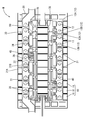
- the perspective view of the battery module of one Embodiment Plan view of battery module Partial enlarged plan view of the battery module
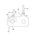
- a perspective view of the temperature detection member attached to the bus bar Top view of the temperature detection member attached to the bus bar
- the battery module M is mounted on a vehicle (not shown) such as an electric vehicle or a hybrid vehicle and used as a power source for driving the vehicle.
- the battery module M includes a single battery group 10 in which a plurality of single batteries 11 (an example of a power storage element) are arranged, and a wiring module 20 attached to the single battery group 10 (see FIGS. 1 and 2).
- the upper side in FIG. 1 is the upper side, and the lower side is the lower side.
- symbol may be attached
- the battery module M of the present embodiment includes a unit cell group 10 in which a plurality of unit cells 11 are arranged (see FIG. 1).
- the unit cell 11 has a flat and substantially rectangular parallelepiped shape, and a power generation element (not shown) is accommodated therein.
- positive and negative electrode terminals 12 ⁇ / b> A and 12 ⁇ / b> B are formed at positions near both ends in the longitudinal direction.
- the positive electrode terminal 12A and the negative electrode terminal 12B have the same shape and size.
- a columnar positioning projection 13 protruding upward is provided at the center of each electrode terminal 12A, 12B.
- the plurality of unit cells 11 are arranged so that adjacent electrode terminals 12 have different polarities, and constitute a unit cell group 10. Adjacent unit cells 11 are electrically connected by a bus bar 21 described later.
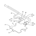
- the wiring module 20 includes a plurality of metal bus bars 21 connected to the positive electrode terminals 12A and the negative electrode terminals 12B of the adjacent unit cells 11, a temperature detection member 40 that detects the temperature of the bus bars 21, and the bus bars 21. And an insulating protector 30 made of an insulating material for holding the temperature detecting member 40.
- bus bar 21 As shown in FIGS. 4 and 5, the bus bar 21 has a substantially square shape as a whole and is overlapped with a part of the adjacent electrode terminal 12 and a connecting portion 25 connected to the electric wire 50. And having.
- the connecting portion 25 extends from the central portion of one edge portion of the main body portion 22 in a direction orthogonal to the extending direction of the edge portion and along the plate surface of the main body portion 22.
- the plate-shaped core wire connection portion 25A is provided and connected to the core wire 51 of the electric wire 50, and the barrel portion 25B is provided on the distal end side and caulked with the outer sheath 52 of the electric wire 50.
- the positioning convex portion 13 of the unit cell 11 described above should be fitted into the center portion of the pair of opposite edge portions on the side where the connection portion 25 and the locking projection 23 are not provided in the main body portion 22.
- a positioning recess 24 cut out in a semicircular shape is formed.
- a bus bar side attachment piece 26 (bus bar side attachment portion) connected to a detection member side attachment piece 44 of a temperature detection member 40 described later. Example) is provided.
- the bus bar side mounting piece 26 extends in parallel to the connecting portion 25, that is, in a direction orthogonal to the extending direction of the edge portion where the bus bar side mounting piece 26 is provided, and along the plate surface of the main body portion 22. Has been.
- the bus bar 21 is formed by pressing a metal plate made of copper, copper alloy, stainless steel (SUS), aluminum or the like into a predetermined shape.
- the temperature detection member 40 includes a temperature detection element 41 configured by, for example, a thermistor, and a heat transfer plate 42 (an example of an attachment portion).
- thermistor a PTC thermistor or an NTC thermistor can be appropriately selected.
- the temperature detection element 41 is not limited to the thermistor, and any element can be appropriately selected as long as the temperature can be detected.
- the heat transfer plate 42 is made of a metal plate material such as copper, copper alloy, stainless steel (SUS), aluminum, and the like.
- a detection member-side attachment piece 44 (an example of an attachment portion) that extends in a direction orthogonal to the extending direction of the edge portion and along the plate surface of the placement portion 43. That is, the entire heat transfer plate 42 is substantially L-shaped in plan view.
- the detection member side attachment piece 44 has a width dimension equivalent to that of the bus bar side attachment piece 26, and is overlapped with the bus bar side attachment piece 26 to come into surface contact.
- the temperature detecting element 41 is fixed in advance to the upper surface of the mounting portion 43 by an insulating adhesive such as an epoxy resin.
- the electric wire 45 is connected to the temperature detection element 41.
- the electric wire 45 is drawn from the side surface of the temperature detection element 41 in a direction along the plate surface of the placement portion 43.
- the electric wire 45 is connected to an external circuit (not shown), and a signal from the temperature detection element 41 is transmitted to the external circuit via the electric wire 45.
- the external circuit is arranged in a battery ECU (not shown), for example, and detects the temperature of the bus bar 21, that is, the temperature of the electrode terminal 12 based on a signal from the temperature detection element 41.
- the insulation protector 30 has an elongated shape in the direction in which the cells 11 are arranged (the left-right direction in FIG. 2).
- the insulation protector 30 is provided with a plurality of bus bar holding portions 31 arranged in two rows that have a partition wall that opens in the vertical direction and has a partition wall that can hold the bus bar 21 by partitioning from the outside.
- the electric wire receiving groove 35 has a pair of groove wall portions 35A and 35B and a bottom portion 35C, and is provided along the arrangement direction of the bus bar holding portions 31 (longitudinal direction of the insulating protector 30).
- Each bus bar holding portion 31 has a rectangular shape in plan view with a size surrounding a pair of adjacent electrode terminals 12A and 12B, and also functions as a protective wall for the pair of adjacent electrode terminals 12A and 12B.
- the outer bottom wall 31A located outside the insulating protector 30 has a center bottom in the extending direction (left and right direction in FIG. 2) of the bus bar 21 superimposed on the electrode terminal 12.
- a locking hole 32 for fitting the locking projection 23 is provided (see FIG. 1).
- the central portion in the extending direction of the inner wall 31B arranged to face the outer wall 31A is cut out vertically so that the bus bar 21 is connected.
- the first passage portion 33 through which the portion 25 is passed (see FIG. 3).
- the first through portion 33 allows the groove-shaped first communication groove 36 that accommodates the connecting portion 25 of the bus bar 21 and the bus bar holding portion 31 to communicate with each other.
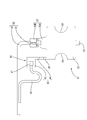
- a second passage portion 34 is formed adjacent to the first passage portion 33 and notched in the vertical direction near one end in the extending direction of the inner wall 31B of the one bus bar holding portion 31.
- the bus bar side mounting piece 26 of the bus bar 21 can be passed therethrough.
- the predetermined bus bar holding portion 31 among the plurality of bus bar holding portions 31 is connected to the second communication groove 37 by the second passing portion 34.
- the second communication groove 37 accommodates the temperature detection member 40 and a part of the electric wire 45 connected to the temperature detection member 40 (temperature detection element 41) and also accommodates the electric wire 45. It leads out to the groove 35 side.
- the second communication groove 37 extends from the second through part 34 of the bus bar holding part 31 toward the inner side of the insulating protector 30 so as to be orthogonal to the inner side wall 31B, meanders in a substantially Z shape, and enters the wire receiving groove 35. On the other hand, it joins in a direction perpendicular to the extending direction.
- the portion where the placement portion 43 of the temperature detection member 40 is disposed is a wide portion 37 ⁇ / b> A that is formed wider than the other portions.
- the groove width of the wide portion 37 ⁇ / b> A is set to be slightly larger than the width of the placement portion 43.
- the electric wire 45 connected to the temperature detection member 40 (temperature detection element 41) is meanderingly routed to the insulating protector 30 along the second communication groove 37 and led out to the electric wire accommodation groove 35 side.
- the groove wall 35A on the bus bar holding part 31 side is partially cut out and is connected to the second communication groove 37 so as to be on the bus bar holding part 31 side.
- the electric wire 45 connected to the temperature detecting member 40 temperature detecting element 41
- a portion of the groove wall portion 35 ⁇ / b> A that faces the first through portion 33 is also cut away, so that the electric wire 50 connected to the connecting portion 25 of the bus bar 21 can be introduced into the electric wire receiving groove 35.
- a regulating piece 38 for restricting the protrusion of the wires 45, 50 from the wire receiving groove 35 is provided from the one groove wall portion 35A, 35B to the other. Projecting toward the groove wall portions 35B and 35A.
- the electric wires 45 and 50 arranged in the electric wire receiving groove 35 are led out of the battery module M and connected to a control unit (not shown) such as an ECU.
- the temperature detection member 40 is accommodated in the second communication groove 37 communicated with the predetermined bus bar holding part 31.
- the mounting portion 43 of the temperature detection member 40 is disposed in the wide portion 37 ⁇ / b> A of the second communication groove 37, and the detection member side attachment piece 44 is overlapped with the bus bar side attachment piece 26.
- the electric wire 45 connected to the temperature detection element 41 is routed along the second communication groove 37 and introduced into the electric wire accommodation groove 35 to be accommodated.
- the plurality of unit cells 11 are arranged so that the adjacent electrode terminals 12A and 12B have different polarities, and the wiring module 20 in which the bus bar 21 and the temperature detection member 40 are arranged is connected to the electrode terminals 12A and 12B of the unit cell group 10. Attach to the surface on which is formed.
- the positioning convex part 13 of the single cell 11 is arranged in the positioning concave part 24 of the bus bar 21, and the bus bar 21 and the electrode terminal 12 are positioned.
- thermoelectric and effect of this embodiment since the temperature detection member 40 is configured to be attached to the bus bar 21 by laser welding, there is no need to provide a fastening member for fixing the temperature detection member 40 to the bus bar 21, and the component The score can be reduced.
- the bus bar side mounting piece 26 is provided on the bus bar 21, and the temperature detection member 40 is provided with the detection member side mounting piece 44.
- the mounting pieces 26 and 44 are not necessarily required.
- the heat transfer plate 142 of the temperature detection member 140 is directly connected to the main body 122 of the bus bar 121. It is good also as a structure which superimposes and laser welding.
- the wiring module 20 in which the bus bar 21 and the temperature detection member 40 are arranged at predetermined positions is attached to the unit cell group 10 and the bus bar 21 and the electrode terminal 12 are laser welded
- the temperature detection member 40 is laser-welded.
- the bus bar 21 and the temperature detection member 40 are thermally connected in advance by laser welding, and then accommodated in the insulating protector 30 in a lump. It is good also as a structure attached to the battery group 10.
- the configuration of the temperature detection member 40 is not limited to the above embodiment, and can be changed as appropriate without departing from the technology disclosed in this specification.
- the shape of the heat transfer plate 142 (attachment portion) can be changed according to the form of the bus bar 121 to be attached.
- the form of the bus bar 21 and the electrode terminal 12 is not limited to the above embodiment.
- the main body portion 122 of the bus bar 121 may have a substantially rectangular shape covering the entire adjacent electrode terminals 12, and the connection portion 125 may be provided near the end of one edge portion of the main body portion 122. .
- connection portion 25 of the bus bar 21 and the core wire 51 of the electric wire 50 are connected by ultrasonic welding, but may be connected by crimping or the like.
- M Battery module 10: Single battery group 11: Single battery (storage element) 12A, 12B: Electrode terminal 20: Wiring module 21: Bus bar 22: Body part 25: Connection part 26: Bus bar side mounting piece (bus bar side mounting part) 30: Insulation protector 31: Bus bar holding part 35: Electric wire receiving groove 40: Temperature detection member 41: Temperature detection element 42: Mounting plate (attachment part) 43: Placement part 44: Detection member side attachment piece (attachment part) 45, 50: Electric wire 51: Core wire
Landscapes
- Chemical Kinetics & Catalysis (AREA)
- General Chemical & Material Sciences (AREA)
- Electrochemistry (AREA)
- Chemical & Material Sciences (AREA)
- Physics & Mathematics (AREA)
- General Physics & Mathematics (AREA)
- Engineering & Computer Science (AREA)
- Manufacturing & Machinery (AREA)
- Nonlinear Science (AREA)
- Connection Of Batteries Or Terminals (AREA)
- Battery Mounting, Suspending (AREA)
- Secondary Cells (AREA)
- Measuring Temperature Or Quantity Of Heat (AREA)
Priority Applications (2)
| Application Number | Priority Date | Filing Date | Title |
|---|---|---|---|
| US15/533,708 US10330536B2 (en) | 2014-12-25 | 2015-12-10 | Structure for attaching temperature detecting member to busbar, wiring module and method for manufacturing wiring module |
| CN201580070119.9A CN107112483B (zh) | 2014-12-25 | 2015-12-10 | 温度检测部件安装到母线的安装结构、布线模块以及布线模块的制造方法 |
Applications Claiming Priority (2)
| Application Number | Priority Date | Filing Date | Title |
|---|---|---|---|
| JP2014261906A JP6315278B2 (ja) | 2014-12-25 | 2014-12-25 | 蓄電モジュール |
| JP2014-261906 | 2014-12-25 |
Publications (1)
| Publication Number | Publication Date |
|---|---|
| WO2016104157A1 true WO2016104157A1 (ja) | 2016-06-30 |
Family
ID=56150187
Family Applications (1)
| Application Number | Title | Priority Date | Filing Date |
|---|---|---|---|
| PCT/JP2015/084603 Ceased WO2016104157A1 (ja) | 2014-12-25 | 2015-12-10 | 温度検知部材のバスバーへの取付構造、配線モジュール、および配線モジュールの製造方法 |
Country Status (4)
| Country | Link |
|---|---|
| US (1) | US10330536B2 (enExample) |
| JP (1) | JP6315278B2 (enExample) |
| CN (1) | CN107112483B (enExample) |
| WO (1) | WO2016104157A1 (enExample) |
Cited By (4)
| Publication number | Priority date | Publication date | Assignee | Title |
|---|---|---|---|---|
| JP2018116814A (ja) * | 2017-01-17 | 2018-07-26 | 矢崎総業株式会社 | 電線配索方法 |
| EP3480573A1 (en) * | 2017-11-07 | 2019-05-08 | Thinking Electronic Industrial Co., Ltd. | Thermo sensor |
| US20240063445A1 (en) * | 2022-08-17 | 2024-02-22 | Te Connectivity Germany Gmbh | Cell Contacting System, Method for Producing a Cell Contacting System and Battery Module |
| WO2024202251A1 (ja) * | 2023-03-24 | 2024-10-03 | 株式会社Aescジャパン | 温度センサ装置、電圧検出装置及び電池モジュール |
Families Citing this family (31)
| Publication number | Priority date | Publication date | Assignee | Title |
|---|---|---|---|---|
| JP6245159B2 (ja) * | 2014-12-17 | 2017-12-13 | 株式会社オートネットワーク技術研究所 | 電池配線モジュール |
| JP2017225259A (ja) * | 2016-06-16 | 2017-12-21 | 東芝三菱電機産業システム株式会社 | 回転機 |
| CN206177474U (zh) * | 2016-08-12 | 2017-05-17 | 泰科电子(上海)有限公司 | 测温组件及电器设备 |
| KR102102927B1 (ko) | 2016-10-06 | 2020-04-21 | 주식회사 엘지화학 | 배터리 모듈, 이러한 배터리 모듈을 포함하는 배터리 팩 및 이러한 배터리 팩을 포함하는 자동차 |
| JP6788794B2 (ja) * | 2016-11-22 | 2020-11-25 | 株式会社オートネットワーク技術研究所 | 配線モジュール |
| US11031728B2 (en) * | 2016-11-23 | 2021-06-08 | Black & Decker Inc. | Electrical connector |
| JP2018120775A (ja) * | 2017-01-26 | 2018-08-02 | 日立オートモティブシステムズ株式会社 | 電池モジュール |
| JP6299898B1 (ja) * | 2017-02-21 | 2018-03-28 | 株式会社オートネットワーク技術研究所 | 接続モジュール |
| JP6688762B2 (ja) * | 2017-05-23 | 2020-04-28 | 矢崎総業株式会社 | 電池用温度センサ及びその取付構造 |
| JP6574814B2 (ja) * | 2017-06-16 | 2019-09-11 | 矢崎総業株式会社 | 導体モジュール取付構造 |
| JP6299917B1 (ja) * | 2017-08-09 | 2018-03-28 | 株式会社オートネットワーク技術研究所 | 接続モジュール |
| US10615396B2 (en) * | 2017-09-08 | 2020-04-07 | Molex, Llc | Battery connection module |
| CN108199101B (zh) * | 2017-12-27 | 2024-10-01 | 上海捷新动力电池系统有限公司 | 一种用于电池模组的温度传感器安装方法及安装装置 |
| DE102018208340B4 (de) * | 2018-05-28 | 2025-05-08 | Bayerische Motoren Werke Aktiengesellschaft | Zellkontaktieranordnung für ein Energiespeichermodul und Verfahren zum Kontaktieren von Energiespeicherzellen eines Energiespeichermoduls |
| JP6738857B2 (ja) * | 2018-06-06 | 2020-08-12 | 矢崎総業株式会社 | センサ保護具 |
| JP2020035588A (ja) * | 2018-08-29 | 2020-03-05 | 株式会社オートネットワーク技術研究所 | 検知端子付きバスバー、蓄電モジュール及び検知端子 |
| JP2020148590A (ja) * | 2019-03-13 | 2020-09-17 | 株式会社オートネットワーク技術研究所 | 測温ユニット、測温ユニットの取付構造、および蓄電モジュール |
| CN115606057B (zh) * | 2019-03-27 | 2026-02-06 | 上海利韬电子有限公司 | 具有集成的过电流保护和过温保护的usb电缆 |
| JP7004231B2 (ja) * | 2019-07-05 | 2022-01-21 | 株式会社オートネットワーク技術研究所 | 配線モジュール |
| JP7375512B2 (ja) * | 2019-12-05 | 2023-11-08 | 株式会社オートネットワーク技術研究所 | 電気接続箱 |
| JP7077295B2 (ja) | 2019-12-26 | 2022-05-30 | 矢崎総業株式会社 | バスバモジュール |
| CN111106492A (zh) * | 2020-01-06 | 2020-05-05 | 北京锦驰泰达科技有限公司 | 一种智能测温导轨端子 |
| JP7078652B2 (ja) | 2020-01-17 | 2022-05-31 | 矢崎総業株式会社 | バスバーモジュール |
| CN213425128U (zh) * | 2020-11-02 | 2021-06-11 | 惠州市乐亿通科技有限公司 | 一种电池模组正负极固定结构 |
| US12352633B2 (en) * | 2021-03-05 | 2025-07-08 | Ultra Clean Holdings, Inc. | Sensing method for cylindrical surfaces |
| JP7598541B2 (ja) * | 2021-08-25 | 2024-12-12 | 株式会社オートネットワーク技術研究所 | 配線モジュール |
| CN216529128U (zh) * | 2021-12-21 | 2022-05-13 | 中创新航科技股份有限公司 | 电池组 |
| US11984566B2 (en) * | 2022-02-22 | 2024-05-14 | GM Global Technology Operations LLC | Battery cell group conductive temperature measurement system |
| US12381266B2 (en) | 2022-07-21 | 2025-08-05 | GM Global Technology Operations LLC | Battery cell group temperature measurement system |
| KR102734122B1 (ko) * | 2022-10-04 | 2024-11-25 | 주식회사 엘지에너지솔루션 | 버스바의 온도측정이 용이한 버스바 어셈블리 및 이를 포함하는 전지 팩 |
| WO2024101399A1 (ja) * | 2022-11-10 | 2024-05-16 | 立山科学株式会社 | 温度センサ固定具 |
Citations (7)
| Publication number | Priority date | Publication date | Assignee | Title |
|---|---|---|---|---|
| WO2010113455A1 (ja) * | 2009-03-31 | 2010-10-07 | 三洋電機株式会社 | 電池モジュール、バッテリシステムおよび電動車両 |
| JP2011091035A (ja) * | 2009-10-22 | 2011-05-06 | Sb Limotive Co Ltd | バッテリーパック及びバスバーホルダー |
| JP2013137905A (ja) * | 2011-12-28 | 2013-07-11 | Aisan Ind Co Ltd | 組電池の監視装置 |
| WO2013176913A1 (en) * | 2012-05-21 | 2013-11-28 | Tyco Electronics Corporation | Boltless battery cell connection |
| JP2014072084A (ja) * | 2012-09-28 | 2014-04-21 | Lithium Energy Japan:Kk | 蓄電装置 |
| JP2014191953A (ja) * | 2013-03-27 | 2014-10-06 | Auto Network Gijutsu Kenkyusho:Kk | 配線モジュール |
| JP2014238938A (ja) * | 2013-06-06 | 2014-12-18 | 株式会社オートネットワーク技術研究所 | 蓄電モジュール |
Family Cites Families (12)
| Publication number | Priority date | Publication date | Assignee | Title |
|---|---|---|---|---|
| KR100754173B1 (ko) * | 2005-03-24 | 2007-09-03 | 삼성전자주식회사 | 네트워크 내에서 콘텐츠 데이터 공유 시스템 및 방법 |
| JP5537111B2 (ja) | 2009-09-30 | 2014-07-02 | 株式会社東芝 | 二次電池装置 |
| KR101913375B1 (ko) * | 2012-06-28 | 2018-10-31 | 에스케이이노베이션 주식회사 | 배터리 모듈 |
| EP2874204B1 (en) * | 2012-07-11 | 2018-06-06 | Nissan Motor Co., Ltd | Battery assembly |
| KR101720614B1 (ko) * | 2013-08-30 | 2017-03-28 | 삼성에스디아이 주식회사 | 배터리 팩 |
| US10396405B2 (en) * | 2014-11-10 | 2019-08-27 | Te Connectivity Corporation | Bus bar for a battery connector system |
| JP6233654B2 (ja) * | 2014-11-25 | 2017-11-22 | 株式会社オートネットワーク技術研究所 | 配線モジュール |
| DE102015002061B4 (de) * | 2015-02-18 | 2023-11-16 | Audi Ag | Elektrische Stromschiene mit Sensoreinheit |
| US10062931B2 (en) * | 2015-04-22 | 2018-08-28 | Johnson Controls Technology Company | Welding process for battery module components |
| US10573938B2 (en) * | 2015-06-25 | 2020-02-25 | Te Connectivity Corporation | Battery module with a temperature monitoring assembly |
| JP6982728B2 (ja) * | 2016-02-01 | 2021-12-17 | パナソニックIpマネジメント株式会社 | バッテリーセンサー装置 |
| JP6572263B2 (ja) * | 2017-06-07 | 2019-09-04 | 矢崎総業株式会社 | バスバモジュール及び電池パック |
-
2014
- 2014-12-25 JP JP2014261906A patent/JP6315278B2/ja not_active Expired - Fee Related
-
2015
- 2015-12-10 CN CN201580070119.9A patent/CN107112483B/zh not_active Expired - Fee Related
- 2015-12-10 US US15/533,708 patent/US10330536B2/en active Active
- 2015-12-10 WO PCT/JP2015/084603 patent/WO2016104157A1/ja not_active Ceased
Patent Citations (7)
| Publication number | Priority date | Publication date | Assignee | Title |
|---|---|---|---|---|
| WO2010113455A1 (ja) * | 2009-03-31 | 2010-10-07 | 三洋電機株式会社 | 電池モジュール、バッテリシステムおよび電動車両 |
| JP2011091035A (ja) * | 2009-10-22 | 2011-05-06 | Sb Limotive Co Ltd | バッテリーパック及びバスバーホルダー |
| JP2013137905A (ja) * | 2011-12-28 | 2013-07-11 | Aisan Ind Co Ltd | 組電池の監視装置 |
| WO2013176913A1 (en) * | 2012-05-21 | 2013-11-28 | Tyco Electronics Corporation | Boltless battery cell connection |
| JP2014072084A (ja) * | 2012-09-28 | 2014-04-21 | Lithium Energy Japan:Kk | 蓄電装置 |
| JP2014191953A (ja) * | 2013-03-27 | 2014-10-06 | Auto Network Gijutsu Kenkyusho:Kk | 配線モジュール |
| JP2014238938A (ja) * | 2013-06-06 | 2014-12-18 | 株式会社オートネットワーク技術研究所 | 蓄電モジュール |
Cited By (8)
| Publication number | Priority date | Publication date | Assignee | Title |
|---|---|---|---|---|
| JP2018116814A (ja) * | 2017-01-17 | 2018-07-26 | 矢崎総業株式会社 | 電線配索方法 |
| EP3480573A1 (en) * | 2017-11-07 | 2019-05-08 | Thinking Electronic Industrial Co., Ltd. | Thermo sensor |
| KR20190001160U (ko) * | 2017-11-07 | 2019-05-15 | 씽킹 일렉트로닉 인더스트리얼 컴퍼니 리미티드 | 온도 센서 |
| KR200491686Y1 (ko) * | 2017-11-07 | 2020-05-19 | 씽킹 일렉트로닉 인더스트리얼 컴퍼니 리미티드 | 온도 센서 |
| US20240063445A1 (en) * | 2022-08-17 | 2024-02-22 | Te Connectivity Germany Gmbh | Cell Contacting System, Method for Producing a Cell Contacting System and Battery Module |
| JP2024028186A (ja) * | 2022-08-17 | 2024-03-01 | ティーイー コネクティビティ ジャーマニー ゲゼルシャフト ミット ベシュレンクテル ハフツンク | セル接触システム、セル接触システムを製造するための方法、およびバッテリモジュール |
| JP7827241B2 (ja) | 2022-08-17 | 2026-03-10 | ティーイー コネクティビティ ジャーマニー ゲゼルシャフト ミット ベシュレンクテル ハフツンク | セル接触システム、セル接触システムを製造するための方法、およびバッテリモジュール |
| WO2024202251A1 (ja) * | 2023-03-24 | 2024-10-03 | 株式会社Aescジャパン | 温度センサ装置、電圧検出装置及び電池モジュール |
Also Published As
| Publication number | Publication date |
|---|---|
| JP2016122577A (ja) | 2016-07-07 |
| US10330536B2 (en) | 2019-06-25 |
| CN107112483A (zh) | 2017-08-29 |
| JP6315278B2 (ja) | 2018-04-25 |
| US20170328783A1 (en) | 2017-11-16 |
| CN107112483B (zh) | 2019-12-17 |
Similar Documents
| Publication | Publication Date | Title |
|---|---|---|
| JP6315278B2 (ja) | 蓄電モジュール | |
| US10553917B2 (en) | Conductor module | |
| JP5910487B2 (ja) | 配線用モジュール | |
| US9024572B2 (en) | Battery module, battery system and electric vehicle | |
| EP4254645B1 (en) | Battery module having improved wire bonding connection structure between bus bar plate and icb assembly, and battery pack including the same | |
| JP6241671B2 (ja) | 温度検知部材のバスバーへの取付構造および配線モジュール | |
| CN103415956B (zh) | 具有稳定测量单元的电池组 | |
| TWI479723B (zh) | 薄形電池模組及使用此模組之電池組 | |
| JP7099054B2 (ja) | 配線モジュール、及び蓄電モジュール | |
| WO2016084760A1 (ja) | 配線モジュール | |
| JP6075150B2 (ja) | 配線モジュール | |
| KR102490605B1 (ko) | 고전압 배터리 서브모듈 | |
| JP6365437B2 (ja) | 配線モジュールおよび蓄電モジュール | |
| JP6590212B2 (ja) | 配線モジュール、及び蓄電モジュール | |
| KR20140063205A (ko) | 전지팩의 전지탭 연결장치 | |
| KR20150104733A (ko) | 리셉터클 구조의 전압 센싱부재를 포함하는 전지모듈 | |
| WO2017010295A1 (ja) | 配線モジュール | |
| JP5915460B2 (ja) | 温度センサの取付構造及び配線モジュールの製造方法 | |
| CN111316464A (zh) | 电化学电池单元组、能量储存模块及其组装方法 | |
| WO2015156188A1 (ja) | 配線モジュール | |
| JP2014165044A (ja) | 接続部材および配線モジュール | |
| JP6610007B2 (ja) | 電池パック | |
| JP6156156B2 (ja) | 配線モジュール | |
| KR102109364B1 (ko) | 친환경자동차용 배터리 모듈 제작방법 |
Legal Events
| Date | Code | Title | Description |
|---|---|---|---|
| 121 | Ep: the epo has been informed by wipo that ep was designated in this application |
Ref document number: 15872726 Country of ref document: EP Kind code of ref document: A1 |
|
| DPE2 | Request for preliminary examination filed before expiration of 19th month from priority date (pct application filed from 20040101) | ||
| WWE | Wipo information: entry into national phase |
Ref document number: 15533708 Country of ref document: US |
|
| NENP | Non-entry into the national phase |
Ref country code: DE |
|
| 122 | Ep: pct application non-entry in european phase |
Ref document number: 15872726 Country of ref document: EP Kind code of ref document: A1 |