WO2016104086A1 - 表示装置、画像形成装置、及び表示方法 - Google Patents
表示装置、画像形成装置、及び表示方法 Download PDFInfo
- Publication number
- WO2016104086A1 WO2016104086A1 PCT/JP2015/083893 JP2015083893W WO2016104086A1 WO 2016104086 A1 WO2016104086 A1 WO 2016104086A1 JP 2015083893 W JP2015083893 W JP 2015083893W WO 2016104086 A1 WO2016104086 A1 WO 2016104086A1
- Authority
- WO
- WIPO (PCT)
- Prior art keywords
- unit
- display
- point
- contact area
- pattern
- Prior art date
- Legal status (The legal status is an assumption and is not a legal conclusion. Google has not performed a legal analysis and makes no representation as to the accuracy of the status listed.)
- Ceased
Links
Images


Classifications
-
- H—ELECTRICITY
- H04—ELECTRIC COMMUNICATION TECHNIQUE
- H04N—PICTORIAL COMMUNICATION, e.g. TELEVISION
- H04N1/00—Scanning, transmission or reproduction of documents or the like, e.g. facsimile transmission; Details thereof
- H04N1/0035—User-machine interface; Control console
- H04N1/00501—Tailoring a user interface [UI] to specific requirements
- H04N1/00506—Customising to the data to be displayed
-
- G—PHYSICS
- G06—COMPUTING OR CALCULATING; COUNTING
- G06F—ELECTRIC DIGITAL DATA PROCESSING
- G06F3/00—Input arrangements for transferring data to be processed into a form capable of being handled by the computer; Output arrangements for transferring data from processing unit to output unit, e.g. interface arrangements
- G06F3/01—Input arrangements or combined input and output arrangements for interaction between user and computer
- G06F3/02—Input arrangements using manually operated switches, e.g. using keyboards or dials
- G06F3/023—Arrangements for converting discrete items of information into a coded form, e.g. arrangements for interpreting keyboard generated codes as alphanumeric codes, operand codes or instruction codes
-
- G—PHYSICS
- G06—COMPUTING OR CALCULATING; COUNTING
- G06F—ELECTRIC DIGITAL DATA PROCESSING
- G06F3/00—Input arrangements for transferring data to be processed into a form capable of being handled by the computer; Output arrangements for transferring data from processing unit to output unit, e.g. interface arrangements
- G06F3/01—Input arrangements or combined input and output arrangements for interaction between user and computer
- G06F3/048—Interaction techniques based on graphical user interfaces [GUI]
- G06F3/0487—Interaction techniques based on graphical user interfaces [GUI] using specific features provided by the input device, e.g. functions controlled by the rotation of a mouse with dual sensing arrangements, or of the nature of the input device, e.g. tap gestures based on pressure sensed by a digitiser
- G06F3/0488—Interaction techniques based on graphical user interfaces [GUI] using specific features provided by the input device, e.g. functions controlled by the rotation of a mouse with dual sensing arrangements, or of the nature of the input device, e.g. tap gestures based on pressure sensed by a digitiser using a touch-screen or digitiser, e.g. input of commands through traced gestures
-
- G—PHYSICS
- G06—COMPUTING OR CALCULATING; COUNTING
- G06F—ELECTRIC DIGITAL DATA PROCESSING
- G06F3/00—Input arrangements for transferring data to be processed into a form capable of being handled by the computer; Output arrangements for transferring data from processing unit to output unit, e.g. interface arrangements
- G06F3/01—Input arrangements or combined input and output arrangements for interaction between user and computer
- G06F3/048—Interaction techniques based on graphical user interfaces [GUI]
- G06F3/0487—Interaction techniques based on graphical user interfaces [GUI] using specific features provided by the input device, e.g. functions controlled by the rotation of a mouse with dual sensing arrangements, or of the nature of the input device, e.g. tap gestures based on pressure sensed by a digitiser
- G06F3/0488—Interaction techniques based on graphical user interfaces [GUI] using specific features provided by the input device, e.g. functions controlled by the rotation of a mouse with dual sensing arrangements, or of the nature of the input device, e.g. tap gestures based on pressure sensed by a digitiser using a touch-screen or digitiser, e.g. input of commands through traced gestures
- G06F3/04886—Interaction techniques based on graphical user interfaces [GUI] using specific features provided by the input device, e.g. functions controlled by the rotation of a mouse with dual sensing arrangements, or of the nature of the input device, e.g. tap gestures based on pressure sensed by a digitiser using a touch-screen or digitiser, e.g. input of commands through traced gestures by partitioning the display area of the touch-screen or the surface of the digitising tablet into independently controllable areas, e.g. virtual keyboards or menus
-
- H—ELECTRICITY
- H04—ELECTRIC COMMUNICATION TECHNIQUE
- H04N—PICTORIAL COMMUNICATION, e.g. TELEVISION
- H04N1/00—Scanning, transmission or reproduction of documents or the like, e.g. facsimile transmission; Details thereof
- H04N1/0035—User-machine interface; Control console
- H04N1/00352—Input means
- H04N1/00384—Key input means, e.g. buttons or keypads
-
- H—ELECTRICITY
- H04—ELECTRIC COMMUNICATION TECHNIQUE
- H04N—PICTORIAL COMMUNICATION, e.g. TELEVISION
- H04N1/00—Scanning, transmission or reproduction of documents or the like, e.g. facsimile transmission; Details thereof
- H04N1/0035—User-machine interface; Control console
- H04N1/00405—Output means
- H04N1/00408—Display of information to the user, e.g. menus
- H04N1/00411—Display of information to the user, e.g. menus the display also being used for user input, e.g. touch screen
-
- H—ELECTRICITY
- H04—ELECTRIC COMMUNICATION TECHNIQUE
- H04N—PICTORIAL COMMUNICATION, e.g. TELEVISION
- H04N2201/00—Indexing scheme relating to scanning, transmission or reproduction of documents or the like, and to details thereof
- H04N2201/0077—Types of the still picture apparatus
- H04N2201/0094—Multifunctional device, i.e. a device capable of all of reading, reproducing, copying, facsimile transception, file transception
Definitions
- the present invention relates to a display device, an image forming apparatus, and a display method.
- the video signal displayed on the screen and the software keyboard are combined to display the screen.
- the keyboard is displayed in an opaque state or a state of low transparency. If no input is made on the keyboard after a predetermined time has elapsed, the keyboard is displayed in a highly transparent state. The user confirms the content displayed on the screen via a highly transparent keyboard.
- the present invention has been made in view of the above problems, and a display device, an image forming apparatus, and an image forming apparatus capable of displaying soft keys on a touch panel with a simple operation while suppressing a decrease in the visibility of contents displayed on the touch panel.
- the purpose is to provide a display method.
- the display device includes a display unit, a detection unit, a storage unit, and a control unit.
- the detection unit detects a contact area where the user contacts the display unit.
- the storage unit stores the pattern.
- the control unit includes a determination unit and a display control unit. The determination unit determines whether or not the contact area matches the pattern.
- the display control unit causes the display unit to display a soft key in response to determining that the determination units match.
- an image forming apparatus includes a display device and an image forming unit according to the first aspect of the present invention.
- the image forming unit forms an image on the sheet.
- the display method is executed by a display device including a display unit.
- the display method includes a procedure for detecting a contact area that a user contacts with the display unit, a procedure for storing a pattern, a procedure for determining whether or not the contact area matches the pattern, and the contact area includes: And displaying a soft key on the display unit in response to the determination that the pattern matches.
- soft keys can be displayed on the touch panel with a simple operation while suppressing a decrease in the visibility of the content displayed on the touch panel.
- the soft key displayed based on a contact area is shown on the display part of the display apparatus which concerns on Embodiment 1 of this invention. It is a flowchart which shows the display method which the display apparatus which concerns on Embodiment 1 of this invention performs. It is a figure which shows the image forming apparatus which concerns on Embodiment 2 of this invention.
- FIG. 1 is a block diagram showing the display device 1.
- the display device 1 includes a control unit 10, a display unit 20, a touch panel 30 as a detection unit, and a storage unit 40.
- FIG. 2A shows a state in which the display unit 20 is touched by the user.
- FIG. 2B shows a state in which the soft key 220 is displayed on the display unit 20.
- the X axis is parallel to the short side of the display unit 20, and the Y axis is parallel to the long side of the display unit 20. That is, the Y axis is parallel to the longitudinal direction of the display unit 20, and the X axis is parallel to a direction orthogonal to the longitudinal direction of the display unit 20.
- the display unit 20 is, for example, a liquid crystal display.
- an operation screen for the user to operate the device on which the display device 1 is mounted is displayed.
- an ID input form 241 and a password input form 242 are displayed on the display unit 20.
- a user inputs an ID into the ID input form 241.
- the password input form 242 the user inputs a password.
- the touch panel 30 detects the contact operation of the hand H that the user contacts with the display unit 20 and the contact area 210.
- the storage unit 40 includes a main storage device (for example, a semiconductor memory) such as a ROM (Read Only Memory) and a RAM (Random Access Memory), and an auxiliary storage device (for example, a hard disk drive).
- a main storage device for example, a semiconductor memory
- ROM Read Only Memory
- RAM Random Access Memory
- auxiliary storage device for example, a hard disk drive
- Various computer programs and patterns executed by the control unit 10 are stored in the ROM.
- the pattern is an image having a shape to be compared with the contact area 210 detected by the touch panel 30 by the control unit 10. Details of the pattern will be described later.
- the control unit 10 includes a determination unit 101 and a display control unit 103.
- the control unit 10 is, for example, a CPU (Central Processing Unit).
- the determination unit 101 determines whether or not the contact area 210 matches the pattern stored in the storage unit 40. Specifically, for example, the storage unit 40 stores a plurality of patterns. The determination unit 101 performs pattern matching between each of the plurality of patterns and the contact area 210. In the present embodiment, pattern matching is a method for searching for a pattern that can be regarded as matching the contact area 210 among a plurality of patterns stored in the storage unit 40.
- the display control unit 103 causes the display unit 20 to display the soft key 220 in response to the determination unit 101 determining that the pattern and the contact area 210 match. Specifically, the display control unit 103 causes the display unit 20 to display the soft key 220 in response to the determination unit 101 determining that there is a pattern that can be regarded as matching the contact area 210 among the plurality of patterns. .
- the soft key 220 is a software numeric keypad in the present embodiment, but the soft key 220 may be a software keyboard or the like.
- the user inputs a value in the ID input form 241 or the password input form 242
- the user touches the soft key 220 corresponding to the input value as a touch operation.
- the touch panel 30 detects a user's touch operation on the soft key 220.
- the control unit 10 inputs a value into the ID input form 241 or the password input form 242 based on the user's contact operation detected by the touch panel 30.
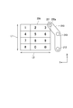
- the display unit 20 may include a detection region 230.
- the detection area 230 is an area for determining whether or not the user's contact operation detected by the touch panel 30 is an incorrect operation.
- the determination unit 101 displays the contact region 210 in the pattern. It is determined whether or not they match.
- the touch panel 30 detects the contact area 210 outside the detection area 230, the determination unit 101 does not determine whether or not the contact area 210 matches the pattern. That is, the determination unit 101 determines that the touch panel 30 has not detected the contact area 210.
- the detection area 230 is arbitrarily set by the user.
- the display unit 20 may include an end region 231.
- the end region 231 is, for example, the periphery of the display unit 20.
- the detection area 230 is preferably set except for the end area 231 of the display unit 20. That is, the end region 231 is preferably different from the detection region 230. In this case, the outside of the detection region 230 described above is the end region 231.
- the determination unit 101 may determine whether or not the contact area 210 matches the pattern in response to detecting a part of the contact area 210 in the detection area 230. Further, the determination unit 101 may determine whether or not the contact area 210 matches the pattern in response to detecting the entire area of the contact area 210 in the detection area 230.
- Control unit 10 further includes a calculation unit 105, a position determination unit 107, and a dimension determination unit 109.
- the display position and size of the soft key 220 on the display unit 20 are determined by the calculation unit 105, the position determination unit 107, and the dimension determination unit 109.
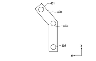
- the plurality of patterns 400 have a first reference 401, a second reference 402, and a third reference 403, respectively.
- the first reference 401 is located at one end of the pattern 400.
- the second reference 402 is located at the other end of the pattern 400.
- the third reference 403 is located between the first reference 401 and the second reference 402 in the pattern 400.
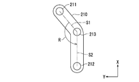
- the calculation unit 105 calculates the first point 211, the second point 212, and the third point 213 of the contact area 210 based on the pattern 400. Specifically, it is as follows.
- the calculation unit 105 calculates the first point 211 of the contact area 210 based on the first reference 401. Accordingly, the first point 211 is located at one end of the contact area 210.
- the calculation unit 105 calculates the second point 212 of the contact area 210 based on the second reference 402. Accordingly, the second point 212 is located at the other end of the contact area 210.
- the calculation unit 105 calculates the third point 213 of the contact area 210 based on the third reference 403. Accordingly, the third point 213 is located between the first point 211 and the second point 212 in the contact area 210.
- the calculation unit 105 further calculates the first line segment S1, the second line segment S2, and the angle R.
- the first line segment S1 is a line segment connecting the first point 211 and the third point 213.
- the second line segment S2 is a line segment connecting the second point 212 and the third point 213.
- the angle R indicates the inclination of the second line segment S2 with respect to the first line segment S1. A specific example of the calculation method of the first line segment S1, the second line segment S2, and the angle R will be described later.
- FIG. 4 shows a soft key 220 displayed based on the contact area 210.
- the position determination unit 107 determines the display position of the soft key 220 on the display unit 20 based on the first point 211.
- the soft key 220 is rectangular and has four corners.
- the position determination unit 107 determines the display position of the soft key 220 such that a predetermined corner is positioned at the first point 211 among the four corners of the soft key 220.
- the position determination unit 107 determines the display position of the soft key 220 so that the upper right corner 220a of the soft key 220 in FIG.
- the position determination unit 107 can determine the display position of the soft key 220 such that any of the four corners of the soft key 220 is positioned at the first point 211. For example, the position determination unit 107 determines the display position of the soft key 220 so that the upper left corner of the soft key 220 in FIG. In addition, the position determination unit 107 can determine the display position of the soft key 220 so that an arbitrary position of the soft key 220 is positioned at the first point 211. Furthermore, the position determination unit 107 can determine the display position of the soft key 220 so that the arbitrary position of the soft key 220 is positioned at the second point 212 or the third point 213.
- the dimension determining unit 109 determines the first dimension L1 of the soft key 220 based on the first point 211 and the second point 212.
- the first dimension L1 of the soft key 220 is a dimension along the X axis of the soft key 220. Specifically, the dimension determining unit 109 determines the length along the X axis from the first point 211 to the second point 212 as the length of the first dimension L1 of the soft key 220.
- the dimension determining unit 109 determines the second dimension L2 of the soft key 220 based on the angle R.
- the second dimension L2 of the soft key 220 is a dimension along the Y axis of the soft key 220.
- the dimension determining unit 109 increases the dimension of the second dimension L2 as the angle R is smaller, and decreases the dimension of the second dimension L2 as the angle R is larger. As a result, the operability of the soft key 220 for the user is improved.
- a maximum value and a minimum value may be set for the length of the second dimension L2 determined based on the angle R.
- the display control unit 103 causes the display unit 20 to display the soft key 220 based on the display position determined by the position determination unit 107 and the dimension determination unit 109, the first dimension L1, and the second dimension L2.
- the soft key 220 is displayed on the display unit 20.
- the vertical width (length along the X axis) of the soft key 220 is the first dimension L1.
- the horizontal width (length along the Y axis) of the soft key 220 is the second dimension L2.
- the contact point detected by the touch panel 30 is represented by position coordinates (X, Y).
- the position coordinates of the first point 211 of the contact area 210 are (3500, 1000).
- the position coordinates of the second point 212 of the contact area 210 are (1500, 500).
- the position coordinates of the third point 213 in the contact area 210 are (3100, 500).
- the first line segment S1 is calculated from the first point 211 and the third point 213 using the three-square theorem.
- the second line segment S2 is calculated from the second point 212 and the third point 213 using the three-square theorem.
- the angle R of the second line segment S2 with respect to the first line segment S1 is calculated using the three-square theorem, and is approximately 128 degrees in this specific example.
- the position determination unit 107 determines the display position of the soft key 220.
- the position coordinates of the corner 220a of the soft key 220 are determined as the position coordinates (3500, 1000) of the first point 211.
- the dimension determining unit 109 determines the first dimension L1 of the soft key 220.
- the dimension determining unit 109 determines the second dimension L2 of the soft key 220.
- the angle R of the second line segment S2 with respect to the first line segment S1 was approximately 128 degrees.
- the soft key 220 is displayed on the display unit 20 when it is determined that the contact area 210 and the pattern 400 match. Therefore, the user can display the soft key 220 on the display unit 20 by touching the display unit 20 so that the contact area 210 matches the pattern 400. As a result, the user can display the soft key 220 on the display unit 20 with a simple operation.
- the soft key 220 is displayed on the display unit 20 based on the position where the user touches the display unit 20. Therefore, the user can display the soft key 220 at an arbitrary position on the display unit 20 with a simple operation. As a result, the user can display the soft key 220 on the display unit 20 while suppressing a decrease in the visibility of the content displayed on the display unit 20.
- the soft key 220 corresponding to the size of the user's hand H is displayed on the display unit 20.
- the operability of the soft key 220 for the user is improved.
- the user when the user touches the soft key 220 with the thumb of the user, the user can operate the soft key 220 as if operating the smartphone. Therefore, when the user operates the smartphone in daily life, the operability of the soft key 220 for the user is further improved.
- the pattern 400 when the pattern 400 has a shape corresponding to the side surface of the user's hand H on the little finger side, the user touches the soft key 220 with the thumb while concealing the soft key 220 with the palm of the user. Can be operated. Therefore, when the user touches the soft key 220 to input highly confidential information, the confidentiality of the information is maintained.
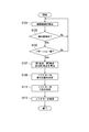
- FIG. 5 is a flowchart showing the display method.
- the soft key 220 is displayed on the display unit 20 according to the display method.
- the display method by executing steps S101 to S113, the soft key 220 based on the contact area 210 of the hand H detected by the touch panel 30 is displayed. Specifically, it is as follows.
- step S101 the touch panel 30 detects the contact area 210 of the user's hand H that touches the display unit 20.
- the determination unit 101 determines whether the touch panel 30 has detected the contact area 210 in the detection area 230. If a negative determination (NO) is made in step S103, the process proceeds to step S101. That is, when the touch panel 30 detects a contact operation in a region that is not the detection region 230, the determination unit 101 determines that the detected contact operation is an erroneous operation. If a positive determination (YES) is made in step S103, the process proceeds to step S105.
- step S105 the determination unit 101 determines whether or not the contact area 210 matches the pattern 400.
- a negative determination NO is made in step S105, that is, when the determination unit 101 determines that the contact area 210 does not match any of the plurality of patterns 400 stored in the storage unit 40
- the processing Returns to step S101.
- an affirmative determination YES is made in step S105, that is, if the determination unit 101 determines that the contact area 210 matches the pattern 400 stored in the storage unit 40, the process proceeds to step S107.
- step S107 the calculation unit 105 calculates the first reference 211, the second reference 212, and the third reference 213 of the contact area 210 based on the pattern 400.
- step S109 the position determining unit 107 determines the display position of the soft key 220 on the display unit 20 based on the first point 211.
- step S111 the dimension determination unit 109 determines the first dimension L1 and the second dimension L2 of the soft key 220 based on the first point 211, the second point 212, and the third point 213.
- step S113 the display control unit 103 displays the soft key 220 based on the display position of the soft key 220 on the display unit 20, the first dimension L1, and the second dimension L2 determined in step S109 and step S111. Displayed on the unit 20.
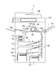
- FIG. 6 shows the image forming apparatus 2.
- the image forming apparatus 2 is, for example, a copying machine, a printer, a facsimile machine, or a multifunction machine.
- the multi-function peripheral includes, for example, at least two devices among a copier, a printer, and a facsimile.
- the image forming apparatus 2 includes a control unit 10, a display unit 20, a touch panel 30, a storage unit 40, a document conveying unit 100, an image reading unit 110, a storage unit 120, a conveying unit 130, and an image forming unit. 140, a fixing unit 150, and a discharge unit 160.
- the sheet T is transported inside the image forming apparatus 2 along the sheet transport direction.
- the control unit 10 functions as the control unit 10 according to the first embodiment
- the display unit 20 functions as the display unit 20 according to the first embodiment
- the touch panel 30 functions as the touch panel 30 according to the first embodiment. Therefore, the control unit 10, the display unit 20, and the touch panel 30 constitute the display device 1 according to the first embodiment.
- the document transport unit 100 transports the document toward the image reading unit 110.
- the image reading unit 110 reads an image of a document and generates image data.
- the storage unit 120 stores the sheet T.
- the storage unit 120 includes a cassette 121 and a manual feed tray 123.
- the cassette 121 stacks sheets T.
- the sheet T is sent out from the cassette 121 or the manual feed tray 123 to the conveyance unit 130.
- the sheet T is, for example, plain paper, copy paper, recycled paper, thin paper, thick paper, glossy paper, or an OHP (Overhead Projector) sheet.
- the control unit 10 controls each element of the image forming apparatus 2. Specifically, when the control unit 10 executes a computer program stored in the storage unit 40, the display unit 20, the touch panel 30, the document conveyance unit 100, the image reading unit 110, the storage unit 120, the conveyance unit 130, The image forming unit 140 and the fixing unit 150 are controlled.
- the control unit 10 is, for example, a CPU (Central Processing Unit).
- the touch panel 30 is arrange
- the conveyance unit 130 conveys the sheet T to the image forming unit 140.
- the image forming unit 140 includes a photosensitive drum 141, a charging unit 142, an exposure unit 143, a developing unit 144, a transfer unit 145, a cleaning unit 146, and a charge eliminating unit 147.
- the image forming unit 140 forms (prints) an image on the sheet T as follows.
- the charging unit 142 charges the surface of the photosensitive drum 141.
- the exposure unit 143 irradiates the surface of the photosensitive drum 141 with light based on the image data generated by the image reading unit 110 or the image data stored in the storage unit 170. As a result, an electrostatic latent image corresponding to the image data is formed on the surface of the photosensitive drum 141.
- the developing unit 144 develops the electrostatic latent image formed on the surface of the photosensitive drum 141 and forms a toner image on the surface of the photosensitive drum 141.
- the transfer unit 145 transfers the toner image to the sheet T.
- the cleaning unit 146 removes toner remaining on the surface of the photosensitive drum 141.
- the neutralization unit 147 removes residual charges on the surface of the photosensitive drum 141.
- the sheet T on which the toner image is transferred is conveyed toward the fixing unit 150.
- the fixing unit 150 heats and pressurizes the sheet T to fix the toner image on the sheet T.
- the sheet T on which the image is fixed is conveyed toward the discharge unit 160.
- the discharge unit 160 discharges the sheet T.
- the display device 1 similar to the first embodiment described with reference to FIGS. 1 to 5 is provided. Therefore, the second embodiment has the same effect as the first embodiment.
- the first and second embodiments have been described above with reference to FIGS.
- the present invention is not limited to the above-described embodiment, and can be implemented in various modes without departing from the gist thereof (for example, (1) to (5) shown below).
- the drawings schematically show each component as a main component, and the thickness, length, number, and the like of each component shown in the drawings are different from the actual for convenience of drawing.
- the shape, dimension, etc. of each component shown by said embodiment are an example, Comprising: It does not specifically limit, A various change is possible in the range which does not deviate substantially from the effect of this invention.
- the calculation unit 105, the position determination unit 107, and the dimension determination unit 109 allow the display position of the soft key 220, the first dimension L1, and A second dimension L2 has been determined.
- at least one of the display position of the soft key 220, the first dimension L1, and the second dimension L2 may be determined by the calculation unit 105, the position determination unit 107, and the dimension determination unit 109.
- the display position of the soft key 220, the first dimension L1, and the second dimension L2 may be predetermined values.
- the soft key 220 was a software numeric keypad.
- the arrangement of the plurality of keys included in the soft key 220 is not limited, and may be an arbitrary arrangement of the user.
- the arrangement of a plurality of keys is changed every time the soft key 220 is displayed on the display unit 20. Also good.
- the storage unit 40 has a pattern for determining whether or not it matches the contact area 210 that touches the display unit 20 with the right hand, and whether or not it matches the contact area 210 that touches the display unit 20 with the left hand. A pattern for determining whether or not is stored.
- an example of the pattern 400 was substantially L-shaped.
- the shape of the pattern 400 may be any shape.
- the pattern 400 has three standards (first standard 401, second standard 402, and third standard 403).
- the pattern 400 may have one reference, and may have a plurality of references other than three.
- the present invention can be used in the field of display devices and image forming apparatuses equipped with display devices.
Landscapes
- Engineering & Computer Science (AREA)
- General Engineering & Computer Science (AREA)
- Theoretical Computer Science (AREA)
- Human Computer Interaction (AREA)
- Multimedia (AREA)
- Signal Processing (AREA)
- Physics & Mathematics (AREA)
- General Physics & Mathematics (AREA)
- User Interface Of Digital Computer (AREA)
- Input From Keyboards Or The Like (AREA)
Abstract
Description
図1及び図2を参照して、本発明の実施形態1に係る表示装置1を説明する。図1は、表示装置1を示すブロック図である。表示装置1は、制御部10と、表示部20と、検出部としてのタッチパネル30と、記憶部40とを備える。
図6を参照して本発明の実施形態2に係る画像形成装置2について説明する。図6は、画像形成装置2を示す。画像形成装置2は、例えば、複写機、プリンター、ファクシミリ、又は複合機である。複合機は、例えば、複写機、プリンター、及びファクシミリのうち少なくとも2つの機器を備える。
Claims (9)
- 表示部と、
前記表示部へのユーザーの接触する接触領域を検出する検出部と、
パターンを記憶する記憶部と、
制御部と、
を備え、
前記制御部は、
前記接触領域が前記パターンに一致するか否かを判定する判定部と、
前記判定部が一致すると判定することに応じて、ソフトキーを前記表示部に表示させる表示制御部と
を含む、表示装置。 - 前記制御部は、
前記パターンに基づいて、前記接触領域の一方端部に位置する第1地点を算出する算出部と、
前記第1地点に基づいて、前記表示部での前記ソフトキーの表示位置を決定する位置決定部と
をさらに含む、請求項1に記載の表示装置。 - 前記算出部は、前記パターンに基づいて、前記接触領域の他方端部に位置する第2地点をさらに算出し、
前記制御部は、前記第1地点及び前記第2地点に基づいて、前記表示部の長手方向に直交する方向に沿った前記ソフトキーの第1寸法を決定する寸法決定部をさらに含む、請求項2に記載の表示装置。 - 前記算出部は、
前記パターンに基づいて、前記接触領域のうち前記第1地点と前記第2地点との間に位置する第3地点と、
前記第1地点と前記第3地点とを結ぶ第1線分と、
前記第3地点と前記第2地点とを結ぶ第2線分と、
前記第1線分に対する前記第2線分の傾きを示す角度と
をさらに算出し、
前記寸法決定部は、前記角度に基づいて、前記表示部の前記長手方向に沿った前記ソフトキーの第2寸法を決定する、請求項3に記載の表示装置。 - 前記表示部は、検出領域を含み、
前記判定部は、前記検出部が前記検出領域で前記接触領域を検出すると、前記接触領域が前記パターンに一致するか否かを判定する、請求項1に記載の表示装置。 - 前記パターンは、前記判定部によって前記接触領域と比較されるための形状を有する、請求項1に記載の表示装置。
- 前記表示部は、前記検出領域と異なる端部領域をさらに含み、
前記端部領域は、前記表示部の周縁であり、
前記判定部は、前記検出部が前記端部領域で前記接触領域を検出すると、前記接触領域が前記パターンに一致するか否かを判定しない、請求項5に記載の表示装置。 - 請求項1に記載の表示装置と、
シートに画像を形成する画像形成部と
を備える、画像形成装置。 - 表示部を備える表示装置が実行する表示方法であって、
前記表示部へのユーザーの接触する接触領域を検出する手順と、
パターンを記憶する手順と、
前記接触領域が前記パターンに一致するか否かを判定する手順と、
前記接触領域が前記パターンに一致すると判定されることに応じて、ソフトキーを前記表示部に表示させる手順と
を含む、表示方法。
Priority Applications (3)
| Application Number | Priority Date | Filing Date | Title |
|---|---|---|---|
| US15/538,333 US10075600B2 (en) | 2014-12-22 | 2015-12-02 | Display device, image forming apparatus, and display method including display of soft key array |
| CN201580069779.5A CN107111438B (zh) | 2014-12-22 | 2015-12-02 | 显示装置、图像形成装置及显示方法 |
| JP2016566074A JP6299883B2 (ja) | 2014-12-22 | 2015-12-02 | 表示装置、画像形成装置、及び表示方法 |
Applications Claiming Priority (2)
| Application Number | Priority Date | Filing Date | Title |
|---|---|---|---|
| JP2014-259165 | 2014-12-22 | ||
| JP2014259165 | 2014-12-22 |
Publications (1)
| Publication Number | Publication Date |
|---|---|
| WO2016104086A1 true WO2016104086A1 (ja) | 2016-06-30 |
Family
ID=56150117
Family Applications (1)
| Application Number | Title | Priority Date | Filing Date |
|---|---|---|---|
| PCT/JP2015/083893 Ceased WO2016104086A1 (ja) | 2014-12-22 | 2015-12-02 | 表示装置、画像形成装置、及び表示方法 |
Country Status (4)
| Country | Link |
|---|---|
| US (1) | US10075600B2 (ja) |
| JP (1) | JP6299883B2 (ja) |
| CN (1) | CN107111438B (ja) |
| WO (1) | WO2016104086A1 (ja) |
Citations (4)
| Publication number | Priority date | Publication date | Assignee | Title |
|---|---|---|---|---|
| JP2008113148A (ja) * | 2006-10-30 | 2008-05-15 | Kyocera Corp | 携帯端末装置における操作キー群のレイアウト方法および操作キー群レイアウト装置 |
| JP2013084144A (ja) * | 2011-10-11 | 2013-05-09 | Yahoo Japan Corp | 情報入力装置、方法及びプログラム |
| JP2013228973A (ja) * | 2012-04-27 | 2013-11-07 | Kyocera Document Solutions Inc | 情報処理装置及び画像形成装置 |
| JP2014191544A (ja) * | 2013-03-27 | 2014-10-06 | Kyocera Corp | 携帯機器、タッチパネルの制限領域設定方法およびプログラム |
Family Cites Families (6)
| Publication number | Priority date | Publication date | Assignee | Title |
|---|---|---|---|---|
| WO2004006080A2 (en) * | 2002-07-04 | 2004-01-15 | Koninklijke Philips Electronics N.V. | Automatically adaptable virtual keyboard |
| CN101523332B (zh) * | 2006-09-28 | 2012-10-24 | 京瓷株式会社 | 便携式终端设备中操作键组的布局方法及实现该布局方法的便携式终端设备 |
| JP4725485B2 (ja) | 2006-10-20 | 2011-07-13 | パナソニック株式会社 | キーボード表示装置 |
| JP4618344B2 (ja) * | 2008-07-29 | 2011-01-26 | コニカミノルタビジネステクノロジーズ株式会社 | 認証装置、認証システム、認証方法、認証プログラムおよび記録媒体 |
| US8504842B1 (en) * | 2012-03-23 | 2013-08-06 | Google Inc. | Alternative unlocking patterns |
| CN103577104B (zh) * | 2013-09-27 | 2017-05-24 | 苏州佳世达电通有限公司 | 一种虚拟键盘的显示方法、控制装置及触摸设备 |
-
2015
- 2015-12-02 WO PCT/JP2015/083893 patent/WO2016104086A1/ja not_active Ceased
- 2015-12-02 US US15/538,333 patent/US10075600B2/en active Active
- 2015-12-02 CN CN201580069779.5A patent/CN107111438B/zh not_active Expired - Fee Related
- 2015-12-02 JP JP2016566074A patent/JP6299883B2/ja not_active Expired - Fee Related
Patent Citations (4)
| Publication number | Priority date | Publication date | Assignee | Title |
|---|---|---|---|---|
| JP2008113148A (ja) * | 2006-10-30 | 2008-05-15 | Kyocera Corp | 携帯端末装置における操作キー群のレイアウト方法および操作キー群レイアウト装置 |
| JP2013084144A (ja) * | 2011-10-11 | 2013-05-09 | Yahoo Japan Corp | 情報入力装置、方法及びプログラム |
| JP2013228973A (ja) * | 2012-04-27 | 2013-11-07 | Kyocera Document Solutions Inc | 情報処理装置及び画像形成装置 |
| JP2014191544A (ja) * | 2013-03-27 | 2014-10-06 | Kyocera Corp | 携帯機器、タッチパネルの制限領域設定方法およびプログラム |
Also Published As
| Publication number | Publication date |
|---|---|
| US10075600B2 (en) | 2018-09-11 |
| JP6299883B2 (ja) | 2018-03-28 |
| CN107111438A (zh) | 2017-08-29 |
| US20170339291A1 (en) | 2017-11-23 |
| CN107111438B (zh) | 2020-06-16 |
| JPWO2016104086A1 (ja) | 2017-10-05 |
Similar Documents
| Publication | Publication Date | Title |
|---|---|---|
| JP5887310B2 (ja) | 表示操作装置 | |
| US9516182B2 (en) | Image forming apparatus that enhances operability on screen displayed as split screens | |
| JP6354642B2 (ja) | 画像読取装置及び画像処理装置 | |
| CN103686041A (zh) | 显示输入装置及具备该显示输入装置的电子设备 | |
| JP6002650B2 (ja) | 表示入力装置及びこれを備えた画像形成装置 | |
| JP2016218841A (ja) | 表示装置、及び画像形成装置 | |
| JP6299883B2 (ja) | 表示装置、画像形成装置、及び表示方法 | |
| JP2017204779A5 (ja) | ||
| JP6631582B2 (ja) | 操作入力装置、情報処理装置、操作入力方法 | |
| JP6361579B2 (ja) | 表示装置、及び画像形成装置 | |
| JP6319201B2 (ja) | 表示装置、及び画像形成装置 | |
| JP2016066248A (ja) | 操作装置、情報処理装置、操作方法 | |
| JP2023165289A (ja) | 画像形成装置及び入力装置 | |
| CN110798583B (zh) | 图像形成装置 | |
| WO2023002838A1 (ja) | 情報処理装置及び情報処理プログラム | |
| JP6014558B2 (ja) | 表示装置 | |
| JP2007310050A (ja) | 操作装置及び画像形成装置 | |
| JP5927342B2 (ja) | 表示装置及び画像形成装置 | |
| JP6350470B2 (ja) | 表示装置、及び画像形成装置 | |
| JP6190925B2 (ja) | 表示装置 | |
| JP2015191323A (ja) | 表示入力装置、情報処理装置 | |
| JP6365293B2 (ja) | 表示装置、画像形成装置、及び表示方法 | |
| JP6311684B2 (ja) | 表示操作装置、及び画像形成装置 | |
| CN115145423A (zh) | 触摸面板装置 | |
| JP5858582B2 (ja) | 表示入力装置および画像形成装置 |
Legal Events
| Date | Code | Title | Description |
|---|---|---|---|
| 121 | Ep: the epo has been informed by wipo that ep was designated in this application |
Ref document number: 15872655 Country of ref document: EP Kind code of ref document: A1 |
|
| ENP | Entry into the national phase |
Ref document number: 2016566074 Country of ref document: JP Kind code of ref document: A |
|
| WWE | Wipo information: entry into national phase |
Ref document number: 15538333 Country of ref document: US |
|
| NENP | Non-entry into the national phase |
Ref country code: DE |
|
| 122 | Ep: pct application non-entry in european phase |
Ref document number: 15872655 Country of ref document: EP Kind code of ref document: A1 |