WO2016104071A1 - 輝度制御装置及び輝度制御方法 - Google Patents
輝度制御装置及び輝度制御方法 Download PDFInfo
- Publication number
- WO2016104071A1 WO2016104071A1 PCT/JP2015/083760 JP2015083760W WO2016104071A1 WO 2016104071 A1 WO2016104071 A1 WO 2016104071A1 JP 2015083760 W JP2015083760 W JP 2015083760W WO 2016104071 A1 WO2016104071 A1 WO 2016104071A1
- Authority
- WO
- WIPO (PCT)
- Prior art keywords
- duty ratio
- interpolation
- unit
- reference duty
- luminance
- Prior art date
- Legal status (The legal status is an assumption and is not a legal conclusion. Google has not performed a legal analysis and makes no representation as to the accuracy of the status listed.)
- Ceased
Links
Images



Classifications
-
- H—ELECTRICITY
- H05—ELECTRIC TECHNIQUES NOT OTHERWISE PROVIDED FOR
- H05B—ELECTRIC HEATING; ELECTRIC LIGHT SOURCES NOT OTHERWISE PROVIDED FOR; CIRCUIT ARRANGEMENTS FOR ELECTRIC LIGHT SOURCES, IN GENERAL
- H05B47/00—Circuit arrangements for operating light sources in general, i.e. where the type of light source is not relevant
- H05B47/10—Controlling the light source
-
- G—PHYSICS
- G09—EDUCATION; CRYPTOGRAPHY; DISPLAY; ADVERTISING; SEALS
- G09G—ARRANGEMENTS OR CIRCUITS FOR CONTROL OF INDICATING DEVICES USING STATIC MEANS TO PRESENT VARIABLE INFORMATION
- G09G3/00—Control arrangements or circuits, of interest only in connection with visual indicators other than cathode-ray tubes
- G09G3/20—Control arrangements or circuits, of interest only in connection with visual indicators other than cathode-ray tubes for presentation of an assembly of a number of characters, e.g. a page, by composing the assembly by combination of individual elements arranged in a matrix no fixed position being assigned to or needed to be assigned to the individual characters or partial characters
- G09G3/2003—Display of colours
-
- G—PHYSICS
- G09—EDUCATION; CRYPTOGRAPHY; DISPLAY; ADVERTISING; SEALS
- G09G—ARRANGEMENTS OR CIRCUITS FOR CONTROL OF INDICATING DEVICES USING STATIC MEANS TO PRESENT VARIABLE INFORMATION
- G09G3/00—Control arrangements or circuits, of interest only in connection with visual indicators other than cathode-ray tubes
- G09G3/20—Control arrangements or circuits, of interest only in connection with visual indicators other than cathode-ray tubes for presentation of an assembly of a number of characters, e.g. a page, by composing the assembly by combination of individual elements arranged in a matrix no fixed position being assigned to or needed to be assigned to the individual characters or partial characters
- G09G3/2007—Display of intermediate tones
- G09G3/2014—Display of intermediate tones by modulation of the duration of a single pulse during which the logic level remains constant
-
- G—PHYSICS
- G09—EDUCATION; CRYPTOGRAPHY; DISPLAY; ADVERTISING; SEALS
- G09G—ARRANGEMENTS OR CIRCUITS FOR CONTROL OF INDICATING DEVICES USING STATIC MEANS TO PRESENT VARIABLE INFORMATION
- G09G3/00—Control arrangements or circuits, of interest only in connection with visual indicators other than cathode-ray tubes
- G09G3/20—Control arrangements or circuits, of interest only in connection with visual indicators other than cathode-ray tubes for presentation of an assembly of a number of characters, e.g. a page, by composing the assembly by combination of individual elements arranged in a matrix no fixed position being assigned to or needed to be assigned to the individual characters or partial characters
- G09G3/34—Control arrangements or circuits, of interest only in connection with visual indicators other than cathode-ray tubes for presentation of an assembly of a number of characters, e.g. a page, by composing the assembly by combination of individual elements arranged in a matrix no fixed position being assigned to or needed to be assigned to the individual characters or partial characters by control of light from an independent source
- G09G3/3406—Control of illumination source
-
- G—PHYSICS
- G09—EDUCATION; CRYPTOGRAPHY; DISPLAY; ADVERTISING; SEALS
- G09G—ARRANGEMENTS OR CIRCUITS FOR CONTROL OF INDICATING DEVICES USING STATIC MEANS TO PRESENT VARIABLE INFORMATION
- G09G3/00—Control arrangements or circuits, of interest only in connection with visual indicators other than cathode-ray tubes
- G09G3/20—Control arrangements or circuits, of interest only in connection with visual indicators other than cathode-ray tubes for presentation of an assembly of a number of characters, e.g. a page, by composing the assembly by combination of individual elements arranged in a matrix no fixed position being assigned to or needed to be assigned to the individual characters or partial characters
- G09G3/34—Control arrangements or circuits, of interest only in connection with visual indicators other than cathode-ray tubes for presentation of an assembly of a number of characters, e.g. a page, by composing the assembly by combination of individual elements arranged in a matrix no fixed position being assigned to or needed to be assigned to the individual characters or partial characters by control of light from an independent source
- G09G3/3406—Control of illumination source
- G09G3/3413—Details of control of colour illumination sources
-
- G—PHYSICS
- G09—EDUCATION; CRYPTOGRAPHY; DISPLAY; ADVERTISING; SEALS
- G09G—ARRANGEMENTS OR CIRCUITS FOR CONTROL OF INDICATING DEVICES USING STATIC MEANS TO PRESENT VARIABLE INFORMATION
- G09G3/00—Control arrangements or circuits, of interest only in connection with visual indicators other than cathode-ray tubes
- G09G3/20—Control arrangements or circuits, of interest only in connection with visual indicators other than cathode-ray tubes for presentation of an assembly of a number of characters, e.g. a page, by composing the assembly by combination of individual elements arranged in a matrix no fixed position being assigned to or needed to be assigned to the individual characters or partial characters
- G09G3/34—Control arrangements or circuits, of interest only in connection with visual indicators other than cathode-ray tubes for presentation of an assembly of a number of characters, e.g. a page, by composing the assembly by combination of individual elements arranged in a matrix no fixed position being assigned to or needed to be assigned to the individual characters or partial characters by control of light from an independent source
- G09G3/3406—Control of illumination source
- G09G3/342—Control of illumination source using several illumination sources separately controlled corresponding to different display panel areas, e.g. along one dimension such as lines
-
- G—PHYSICS
- G09—EDUCATION; CRYPTOGRAPHY; DISPLAY; ADVERTISING; SEALS
- G09G—ARRANGEMENTS OR CIRCUITS FOR CONTROL OF INDICATING DEVICES USING STATIC MEANS TO PRESENT VARIABLE INFORMATION
- G09G3/00—Control arrangements or circuits, of interest only in connection with visual indicators other than cathode-ray tubes
- G09G3/20—Control arrangements or circuits, of interest only in connection with visual indicators other than cathode-ray tubes for presentation of an assembly of a number of characters, e.g. a page, by composing the assembly by combination of individual elements arranged in a matrix no fixed position being assigned to or needed to be assigned to the individual characters or partial characters
- G09G3/34—Control arrangements or circuits, of interest only in connection with visual indicators other than cathode-ray tubes for presentation of an assembly of a number of characters, e.g. a page, by composing the assembly by combination of individual elements arranged in a matrix no fixed position being assigned to or needed to be assigned to the individual characters or partial characters by control of light from an independent source
- G09G3/3406—Control of illumination source
- G09G3/342—Control of illumination source using several illumination sources separately controlled corresponding to different display panel areas, e.g. along one dimension such as lines
- G09G3/3426—Control of illumination source using several illumination sources separately controlled corresponding to different display panel areas, e.g. along one dimension such as lines the different display panel areas being distributed in two dimensions, e.g. matrix
-
- G—PHYSICS
- G09—EDUCATION; CRYPTOGRAPHY; DISPLAY; ADVERTISING; SEALS
- G09G—ARRANGEMENTS OR CIRCUITS FOR CONTROL OF INDICATING DEVICES USING STATIC MEANS TO PRESENT VARIABLE INFORMATION
- G09G3/00—Control arrangements or circuits, of interest only in connection with visual indicators other than cathode-ray tubes
- G09G3/20—Control arrangements or circuits, of interest only in connection with visual indicators other than cathode-ray tubes for presentation of an assembly of a number of characters, e.g. a page, by composing the assembly by combination of individual elements arranged in a matrix no fixed position being assigned to or needed to be assigned to the individual characters or partial characters
- G09G3/34—Control arrangements or circuits, of interest only in connection with visual indicators other than cathode-ray tubes for presentation of an assembly of a number of characters, e.g. a page, by composing the assembly by combination of individual elements arranged in a matrix no fixed position being assigned to or needed to be assigned to the individual characters or partial characters by control of light from an independent source
- G09G3/3433—Control arrangements or circuits, of interest only in connection with visual indicators other than cathode-ray tubes for presentation of an assembly of a number of characters, e.g. a page, by composing the assembly by combination of individual elements arranged in a matrix no fixed position being assigned to or needed to be assigned to the individual characters or partial characters by control of light from an independent source using light modulating elements actuated by an electric field and being other than liquid crystal devices and electrochromic devices
-
- G—PHYSICS
- G09—EDUCATION; CRYPTOGRAPHY; DISPLAY; ADVERTISING; SEALS
- G09G—ARRANGEMENTS OR CIRCUITS FOR CONTROL OF INDICATING DEVICES USING STATIC MEANS TO PRESENT VARIABLE INFORMATION
- G09G3/00—Control arrangements or circuits, of interest only in connection with visual indicators other than cathode-ray tubes
- G09G3/20—Control arrangements or circuits, of interest only in connection with visual indicators other than cathode-ray tubes for presentation of an assembly of a number of characters, e.g. a page, by composing the assembly by combination of individual elements arranged in a matrix no fixed position being assigned to or needed to be assigned to the individual characters or partial characters
- G09G3/34—Control arrangements or circuits, of interest only in connection with visual indicators other than cathode-ray tubes for presentation of an assembly of a number of characters, e.g. a page, by composing the assembly by combination of individual elements arranged in a matrix no fixed position being assigned to or needed to be assigned to the individual characters or partial characters by control of light from an independent source
- G09G3/36—Control arrangements or circuits, of interest only in connection with visual indicators other than cathode-ray tubes for presentation of an assembly of a number of characters, e.g. a page, by composing the assembly by combination of individual elements arranged in a matrix no fixed position being assigned to or needed to be assigned to the individual characters or partial characters by control of light from an independent source using liquid crystals
- G09G3/3611—Control of matrices with row and column drivers
- G09G3/3648—Control of matrices with row and column drivers using an active matrix
-
- H—ELECTRICITY
- H05—ELECTRIC TECHNIQUES NOT OTHERWISE PROVIDED FOR
- H05B—ELECTRIC HEATING; ELECTRIC LIGHT SOURCES NOT OTHERWISE PROVIDED FOR; CIRCUIT ARRANGEMENTS FOR ELECTRIC LIGHT SOURCES, IN GENERAL
- H05B45/00—Circuit arrangements for operating light-emitting diodes [LED]
- H05B45/20—Controlling the colour of the light
- H05B45/24—Controlling the colour of the light using electrical feedback from LEDs or from LED modules
-
- H—ELECTRICITY
- H05—ELECTRIC TECHNIQUES NOT OTHERWISE PROVIDED FOR
- H05B—ELECTRIC HEATING; ELECTRIC LIGHT SOURCES NOT OTHERWISE PROVIDED FOR; CIRCUIT ARRANGEMENTS FOR ELECTRIC LIGHT SOURCES, IN GENERAL
- H05B45/00—Circuit arrangements for operating light-emitting diodes [LED]
- H05B45/50—Circuit arrangements for operating light-emitting diodes [LED] responsive to malfunctions or undesirable behaviour of LEDs; responsive to LED life; Protective circuits
- H05B45/58—Circuit arrangements for operating light-emitting diodes [LED] responsive to malfunctions or undesirable behaviour of LEDs; responsive to LED life; Protective circuits involving end of life detection of LEDs
-
- H—ELECTRICITY
- H05—ELECTRIC TECHNIQUES NOT OTHERWISE PROVIDED FOR
- H05B—ELECTRIC HEATING; ELECTRIC LIGHT SOURCES NOT OTHERWISE PROVIDED FOR; CIRCUIT ARRANGEMENTS FOR ELECTRIC LIGHT SOURCES, IN GENERAL
- H05B47/00—Circuit arrangements for operating light sources in general, i.e. where the type of light source is not relevant
- H05B47/10—Controlling the light source
- H05B47/16—Controlling the light source by timing means
Definitions
- the present invention relates to a luminance control device and a luminance control method for controlling the luminance of a light emitting member.
- a light emitting element such as an LED element or an organic EL element may be controlled so that the luminance gradually changes by a fade-in process or a fade-out process.
- the luminance of the light emitting element is controlled by pulse width modulation control, the duty ratio of the pulse current or pulse voltage for driving the light emitting element is changed in each of a plurality of unit periods in the luminance transition period.
- the difference (change width) in the reference duty ratio between adjacent unit periods is large, the discontinuous change in luminance is likely to be visually recognized by the user, which may give a sense of discomfort.
- a luminance control device that integrates a unit luminance change width finer than a predetermined luminance change width, which is a difference between reference duty ratios in adjacent unit periods, into the reference duty ratio every time a period shorter than the unit period elapses.
- a luminance control device that integrates a unit luminance change width finer than a predetermined luminance change width, which is a difference between reference duty ratios in adjacent unit periods, into the reference duty ratio every time a period shorter than the unit period elapses.
- the sense of discomfort given to the user is reduced by reducing the change width of the luminance of the light emitting element.
- the reference duty ratio and the unit luminance change width in each unit period may be stored, and an increase in the amount of information is suppressed.
- the luminance change rate is constant, that is, the difference in the reference duty ratio is set smaller between the low luminance unit periods than between the high luminance unit periods.
- the predetermined luminance change width and the unit luminance change width are constant, and the luminance change rate becomes larger in the low luminance unit period than in the high luminance unit period. There may be cases where the sense of incongruity cannot be sufficiently suppressed.
- the unit luminance change width is individually set and stored in each unit period. Must be done, and the amount of information becomes large.
- An object of the present invention is to provide a luminance control device and a luminance control method capable of controlling the luminance of a light emitting element so as not to give a sense of incongruity to a user while suppressing the amount of information to be stored.
- the invention described in claim 1 is characterized in that a duty ratio of a pulse current or a pulse voltage for driving a light emitting member is divided into a plurality of unit periods obtained by equally dividing a luminance transition period.
- a luminance control device that controls the luminance of the light emitting member by changing the duty ratio storage means for storing a reference duty ratio in each of the plurality of unit periods, and a division number storage means for storing the interpolation division number And an interpolation change in the one unit period by dividing a value obtained by subtracting the reference duty ratio in one unit period from the reference duty ratio in the next unit period among the plurality of unit periods by the interpolation division number.
- an interpolation period obtained by further dividing the unit period by the number of interpolation divisions has elapsed in each of the plurality of unit periods.
- the reference duty ratio in each of the plurality of unit periods is set to increase or decrease stepwise. It is a feature.
- the difference between the reference duty ratio in one unit period and the reference duty ratio in the next unit period among the plurality of unit periods is Further, the smaller the reference duty ratio of the one unit period is, the smaller the setting is set.
- the light emitting member includes a plurality of light emitting elements having different emission colors
- the duty ratio storage means is The reference duty ratio is stored for each of the emission colors
- the calculation means calculates the interpolation change width for each of the emission colors
- the integration means changes the interpolation change to the reference duty ratio for each of the emission colors.
- the width is integrated, and the control unit causes the light-emitting element to emit light at a duty ratio for each of the emission colors obtained by the integration unit.
- the invention according to claim 5 controls the luminance of the light emitting member by changing the duty ratio of the pulse current or pulse voltage for driving the light emitting member in each of a plurality of unit periods obtained by equally dividing the luminance transition period.
- a luminance control method for storing a reference duty ratio and an interpolation division number in each of the plurality of unit periods, and setting a reference duty ratio in one unit period of the plurality of unit periods to a next unit A value subtracted from the reference duty ratio in the period is divided by the number of interpolation divisions to calculate an interpolation change width in the one unit period.
- the unit period is further calculated by the interpolation division number. Every time the divided interpolation period elapses, the interpolation change width is integrated into the reference duty ratio of the unit period, and the duty ratio
- the interpolation change width is integrated with the reference duty ratio every time the interpolation period elapses in each of the plurality of unit periods, the change width of the luminance of the light emitting member is reduced. This makes it difficult for the user to feel uncomfortable.
- the interpolation change width is calculated by dividing the value obtained by subtracting the reference duty ratio in one unit period from the reference duty ratio in the next unit period by the number of interpolation divisions. It is only necessary to store the number of interpolation steps and the reference duty ratio in each unit period, and the amount of information to be stored can be suppressed.
- the interpolation change width can be calculated even if the difference between the reference duty ratios in adjacent unit periods is not constant, and the interpolation change in each unit period can be determined by appropriately setting the reference duty ratio in each unit period.
- the width can be set to an appropriate value. For example, if the difference in duty ratio with the next unit period is reduced in a low-luminance unit period, the amount of change in interpolation in the low-luminance unit period can be reduced, making it more difficult for the user to feel uncomfortable. Can do.
- “difference” means an absolute value.
- the luminance of the light emitting member is increased or decreased stepwise, for example, fade.
- In-process and fade-out process can be executed.
- the difference between the reference duty ratio in one unit period and the reference duty ratio in the next unit period becomes smaller as the reference duty ratio in one unit period becomes smaller. Further, as the unit period of low luminance is decreased, the change width of the interpolation can be reduced to reduce the change width of the luminance of the light emitting member, and the user can be made more difficult to feel uncomfortable.
- the light-emitting member is composed of a plurality of light-emitting elements having different emission colors, and each light-emitting element is caused to emit light at a duty ratio for each emission color obtained by the integrating means. For this reason, it is possible to appropriately adjust the balance of the luminance of the light emitting elements of the respective emission colors to cause the light emitting member to emit light in an appropriate emission color, and to change the luminance so that the user does not feel uncomfortable.
- the interpolation change width is calculated by dividing the value obtained by subtracting the reference duty ratio in one unit period from the reference duty ratio in the next unit period by the number of interpolation steps, Since the interpolated variation width is added to the reference duty ratio in the unit period and the luminance of the light emitting member is changed, the amount of information stored as described above is suppressed, and the light emitting element is less likely to feel uncomfortable for the user.
- the brightness can be changed.
- the brightness control apparatus 1 of the present embodiment includes a microcomputer 2 (hereinafter referred to as ⁇ COM 2) and an LED driver as control means for receiving a signal from the ⁇ COM 2 and lighting the LED 4 as a light emitting member. 3 is mounted on a vehicle (not shown), for example, and the LED 4 is turned on and off, and the brightness at the time of lighting is controlled.
- ⁇ COM 2 microcomputer 2
- LED driver as control means for receiving a signal from the ⁇ COM 2 and lighting the LED 4 as a light emitting member.
- 3 is mounted on a vehicle (not shown), for example, and the LED 4 is turned on and off, and the brightness at the time of lighting is controlled.
- the ⁇ COM 2 includes a central processing unit 21 (hereinafter referred to as a CPU 21) that performs various processes in accordance with a program, a ROM 22 that is a read-only memory that stores a program for processing executed by the CPU 21, and various processing steps in the CPU 21. And a RAM 23 which is a readable / writable memory having a work area used in the data storage and a data storage area for storing various data. Further, the input means 5 is connected to the CPU 21.
- a CPU 21 central processing unit 21
- ROM 22 that is a read-only memory that stores a program for processing executed by the CPU 21, and various processing steps in the CPU 21.
- a RAM 23 which is a readable / writable memory having a work area used in the data storage and a data storage area for storing various data.
- the input means 5 is connected to the CPU 21.
- the ROM 22 functions as duty ratio storage means by storing the fade table for fade-in processing and the fade table for fade-out processing shown in Table 1, and also stores the interpolation number Nd by storing the interpolation division number Nd. Function as.
- the reference duty ratio in each of the plurality of unit periods is set to increase stepwise, and in the fade-out process, the reference duty ratio in each of the plurality of unit periods decreases stepwise. Is set to
- the brightness of the LED 4 is changed by setting the length TW of the brightness transition period in which the fade-in process is performed to 0.5 seconds and the length T of each unit period to 0.1 seconds.
- the interpolation division number Nd is set to 10
- the interpolation period ⁇ T obtained by dividing the unit period T by the interpolation division number Nd is set to 0.01 seconds.
- the smaller the reference duty ratio Dn the smaller the difference ⁇ Dn from the reference duty ratio Dn + 1 of the next unit period is set.
- the smaller the reference duty ratio Dn is, the smaller the interpolation change width Dn ′ obtained by dividing the value obtained by subtracting the reference duty ratio Dn from the reference duty ratio Dn + 1 by the interpolation division number Nd is set.
- the LED driver 3 is connected to a power source (not shown) and is configured to light the LED 4 by pulse width modulation control.
- the brightness of the LED 4 can be controlled by adjusting the duty ratio of the pulse current or pulse voltage that drives the LED 4. It is configured.
- the LED driver 3 drives the LED 4 with a duty ratio corresponding to the signal received from the ⁇ COM 2.
- the LED 4 has a plurality of LED elements as light emitting elements, is configured to emit light with a predetermined light emission color, and is used as, for example, vehicle interior lighting.
- the input means 5 is connected to, for example, a means for detecting opening / closing of the vehicle door, and transmits an ON signal to the ⁇ COM 2 when the vehicle door is opened, and transmits an OFF signal to the ⁇ COM 2 when the vehicle door is closed.
- the input means 5 may continue to transmit an ON signal when the vehicle door is open, and may be configured not to transmit a signal when the vehicle door is closed. And an ON signal may be transmitted at an appropriate timing.
- a fade table for the fade-out process may be read, and the same procedure as the following fade-in process is performed.
- the CPU 21 of the ⁇ COM 2 starts the fade-in process shown in FIG. 2 when the vehicle door is opened and the ON signal is received from the input means 5.
- the CPU 21 may start the process by receiving an off signal or no longer receiving an on signal.
- the CPU 21 stores a table counter that stores a value of n indicating that it is the n-th unit period, and a calculation counter that stores an interpolation change width integration count k described later.
- the CPU 21 reads the reference duty ratio Dn of the nth unit period and the reference duty ratio Dn + 1 of the next n + 1 unit period from the fade table for fade-in processing stored in the ROM 22 (S120).
- the CPU 21 executes the interpolation process shown in FIG. 3 (S130).
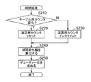
- the CPU 21 first determines whether or not the value n of the table counter has changed immediately before the transition to the interpolation process (that is, whether or not the process has passed through step S160 described later) (S210).
- n changes Y in S210
- the CPU 21 calculates an interpolation change width Dn ′ by dividing a value obtained by subtracting the reference duty ratio Dn in the nth unit period from the reference duty ratio Dn + 1 in the (n + 1) th unit period by the interpolation division number Nd (S240).
- the CPU 21 adds a value obtained by multiplying the interpolation change width Dn ′ by the value k of the calculation counter to the reference duty ratio Dn of the n-th unit period, and obtains the duty ratio D at that time (S250).
- the interpolation process is terminated.
- k increases by 1 every time one interpolation process is executed. Therefore, the duty ratio D increases by the interpolation change width Dn ′ for each interpolation process. That is, the interpolation change width Dn ′ is integrated with the reference duty ratio Dn.
- the CPU 21 returns to the fade-in process again, and transmits a signal to the LED driver 3 so that the LED 4 is lit at the duty ratio D obtained in S250 (S140). Note that the LED driver 3 continues lighting the LED 4 with a constant duty ratio until the signal is received from the CPU 21 again. Further, the CPU 21 has a timer function, and waits at an appropriate timing in the fade-in process so that a signal is transmitted to the LED driver 3 with an interval of the interpolation period ⁇ T every time step S140 is reached.
- the CPU 21 determines whether or not the value k of the calculation counter is equal to the interpolation division number Nd (S150). When the value k of the calculation counter is not equal to the interpolation division number Nd (N in S150), the CPU 21 determines that the n-th unit period continues and returns to step S130 again. On the other hand, when the value k of the calculation counter is equal to the interpolation division number Nd (Y in S150), the CPU 21 determines that the n-th unit period has ended, and increments the value n of the table counter by 1 (S160).
- step S160 the CPU 21 determines whether or not the value n of the table counter is equal to Nl (5 in the present embodiment) indicating the last unit period (S170).
- n of the table counter is not equal to Nl (N in S170)
- the CPU 21 returns to step S120 again.
- the value n of the table counter is equal to Nl (Y in S170)
- the CPU 21 ends the fade-in process.
- the CPU 21 that executes the process of step S240 in the flowchart of FIG. 3 corresponds to the calculating means
- the CPU 21 that executes the process of S250 corresponds to the integrating means.
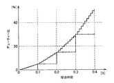
- the duty ratio D for driving the LED 4 becomes a value obtained by integrating the interpolation change width Dn ′ with the reference duty ratio Dn every time the interpolation period ⁇ T elapses. 5 changes with time as indicated by a solid line. That is, the duty ratio D in each unit period increases by the interpolation change width Dn ′, and the interpolation change width Dn ′ increases as n increases.
- the duty ratio D changes by the interpolation change width Dn ′, so that the change width of the brightness of the LED 4 is reduced to make it difficult for the user to feel uncomfortable. be able to.
- the interpolation stage number Nd and the reference duty ratio Dn in each unit period may be stored, the amount of information can be suppressed, and the reference duty ratio in adjacent unit periods can be suppressed. Even if the difference ⁇ Dn of Dn is not constant, the interpolation change width Dn ′ can be calculated. Further, the CPU 21 can calculate the interpolation change width Dn ′ by simple calculation of subtraction, division, and addition.
- the luminance control device 1 controls the LED 4 as a light emitting member that can emit light in a predetermined light emitting color, but the light emitting member has a plurality of light emitting elements having different light emitting colors.
- the entire emission color may be adjustable, and for example, an LED having LED elements of RGB three primary colors may be used.
- the ROM stores a fade table for each light emission color of the three primary colors, and the CPU calculates an interpolation change width for each light emission color and integrates it to the reference duty ratio of each light emission color. What is necessary is just to obtain
- the brightness control method is exemplified by the fade-in process and the fade-out process.
- the change of the reference duty ratio in the brightness control method may be set as appropriate.
- the light emitting member emits light.
- the duty ratio may be changed so as to increase the luminance from the state where the light is on, or the duty ratio may be changed so as to be low enough not to be turned off. Further, for example, the duty ratio may be changed so that the luminance does not monotonously increase or monotonically decrease so that the luminance is once increased and then decreased.
- the luminance control apparatus 1 shall be provided in a vehicle, the luminance control apparatus should just be provided so that the brightness
- the light emitting member is not limited to the LED element, and may include, for example, an organic EL element as long as the luminance is controlled by controlling the duty ratio.
- Brightness control device 3 LED driver (control means) 4 LED (light emitting member) 21 CPU (calculation means, integration means) 22 ROM (duty ratio storage means, division number storage means)
Landscapes
- Engineering & Computer Science (AREA)
- Physics & Mathematics (AREA)
- Computer Hardware Design (AREA)
- General Physics & Mathematics (AREA)
- Theoretical Computer Science (AREA)
- Chemical & Material Sciences (AREA)
- Crystallography & Structural Chemistry (AREA)
- Circuit Arrangement For Electric Light Sources In General (AREA)
Abstract
記憶する情報量を抑制しつつ、利用者に違和感を与えにくいように発光素子の輝度を制御することができる輝度制御装置及び輝度制御方法を提供する。CPU(21)が、基準デューティ比(Dn+1)から基準デューティ比(Dn)を減じた値を補間分割数(Nd)で除して補間変化幅(Dn')を算出し、補間期間(ΔT)が経過する毎に基準デューティ比に補間変化幅(Dn')を積算していくことにより、LED(4)の輝度の変化幅を小さくして利用者に違和感を与えにくくするとともに、記憶する情報量を抑制することができる。
Description
本発明は、発光部材の輝度を制御する輝度制御装置及び輝度制御方法に関する。
一般に、LED素子や有機EL素子等の発光素子は、フェードイン処理又はフェードアウト処理によって徐々に輝度が変化するように制御されることがある。パルス幅変調制御によって発光素子の輝度を制御する場合、発光素子を駆動するパルス電流又はパルス電圧のデューティ比を輝度遷移期間内における複数の単位期間のそれぞれで変化させる。このとき、隣り合う単位期間における基準デューティ比の差分(変化幅)が大きいと、輝度の不連続な変化が利用者に視認されやすくなり、違和感を与えてしまう可能性がある。一方、基準デューティ比の変化幅を小さくしようとすると、輝度遷移期間を多くの単位期間に分割する必要があるとともに、単位期間毎に基準デューティ比を記憶しなければならず、記憶する情報量が大きくなってしまう。
そこで、隣り合う単位期間における基準デューティ比の差分である所定輝度変化幅よりも微細な単位輝度変化幅を、単位期間よりも短い期間が経過する毎に基準デューティ比に積算していく輝度制御装置が開示されている(例えば、特許文献1参照)。このような輝度制御装置では、発光素子の輝度の変化幅を小さくすることにより、利用者に与える違和感の軽減を図っている。また、それぞれの単位期間における基準デューティ比と単位輝度変化幅とを記憶すればよく、情報量の増大を抑制している。
ところで、発光素子の輝度が段階的に変化する際、輝度の変化率が大きいほど利用者に違和感を与えやすくなる。従って、輝度の変化率を一定にする、即ち、低輝度の単位期間同士の間において、高輝度の単位期間同士の間よりも基準デューティ比の差分を小さく設定することが好ましい。しかしながら、特許文献1に記載の輝度制御装置では、所定輝度変化幅および単位輝度変化幅が一定であり、低輝度の単位期間において高輝度の単位期間よりも輝度の変化率が大きくなってしまい、違和感を充分に抑制できないことがある。そこで、低輝度の単位期間における輝度の変化幅を小さくするために、低輝度の単位期間ほど単位輝度変化幅を小さくしようとすると、それぞれの単位期間において単位輝度変化幅を個別に設定して記憶しなければならず、情報量が大きくなってしまう。
本発明の目的は、記憶する情報量を抑制しつつ、利用者に違和感を与えにくいように発光素子の輝度を制御することができる輝度制御装置及び輝度制御方法を提供することにある。
前記課題を解決し目的を達成するために、請求項1に記載された発明は、発光部材を駆動するパルス電流又はパルス電圧のデューティ比を、輝度遷移期間を等分割した複数の単位期間のそれぞれで変化させることで該発光部材の輝度を制御する輝度制御装置であって、前記複数の単位期間のそれぞれにおける基準デューティ比を記憶するデューティ比記憶手段と、補間分割数を記憶する分割数記憶手段と、前記複数の単位期間のうち一の単位期間における前記基準デューティ比をその次の単位期間における前記基準デューティ比から減じた値を前記補間分割数で除して当該一の単位期間における補間変化幅を算出する算出手段と、前記複数の単位期間のそれぞれにおいて、前記単位期間を前記補間分割数でさらに等分割した補間期間が経過する毎に当該単位期間の前記基準デューティ比に前記補間変化幅を積算していく積算手段と、前記積算手段によって求めたデューティ比で前記発光部材を発光させる制御手段と、を備えることを特徴とする輝度制御装置である。
請求項2に記載された発明は、請求項1に記載の発明において、前記複数の単位期間のそれぞれにおける前記基準デューティ比が、段階的に増加又は減少していくように設定されていることを特徴とするものである。
請求項3に記載された発明は、請求項2に記載の発明において、前記複数の単位期間のうち一の単位期間における前記基準デューティ比とその次の単位期間における前記基準デューティ比との差分が、当該一の単位期間の前記基準デューティ比が小さいほど小さくなるように設定されていることを特徴とするものである。
請求項4に記載された発明は、請求項1~3のいずれか1項に記載の発明において、前記発光部材が、互いに異なる発光色を有する複数の発光素子を備え、前記デューティ比記憶手段が、前記発光色毎に前記基準デューティ比を記憶し、前記算出手段が、前記発光色毎に前記補間変化幅を算出し、前記積算手段が、前記発光色毎に前記基準デューティ比に前記補間変化幅を積算し、前記制御手段が、前記積算手段によって求めた前記発光色毎のデューティ比で前記発光素子を発光させることを特徴とするものである。
請求項5に記載された発明は、発光部材を駆動するパルス電流又はパルス電圧のデューティ比を、輝度遷移期間を等分割した複数の単位期間のそれぞれで変化させることで該発光部材の輝度を制御する輝度制御方法であって、前記複数の単位期間のそれぞれにおける基準デューティ比と、補間分割数と、を記憶し、前記複数の単位期間のうち一の単位期間における基準デューティ比をその次の単位期間における基準デューティ比から減じた値を前記補間分割数で除して当該一の単位期間における補間変化幅を算出し、前記複数の単位期間のそれぞれにおいて、前記単位期間を前記補間分割数でさらに分割した補間期間が経過する毎に当該単位期間の前記基準デューティ比に前記補間変化幅を積算していくとともに、このデューティ比で前記発光部材を発光させることを特徴とする輝度制御方法である。
請求項1に記載された発明によれば、複数の単位期間のそれぞれにおいて補間期間が経過する毎に基準デューティ比に補間変化幅を積算していくことから、発光部材の輝度の変化幅を小さくして利用者に違和感を与えにくくすることができる。また、補間変化幅が、一の単位期間における基準デューティ比を次の単位期間における基準デューティ比から減じた値を補間分割数で除して算出されることから、補間変化幅を算出するために補間段階数と各単位期間における基準デューティ比とを記憶すればよく、記憶する情報量を抑制することができる。このとき、隣り合う単位期間における基準デューティ比の差分が一定でなくても補間変化幅を算出することができ、各単位期間の基準デューティ比を適宜に設定することにより、各単位期間における補間変化幅を適宜な値にすることができる。例えば、低輝度の単位期間においてその次の単位期間とのデューティ比の差分を小さくすれば、低輝度の単位期間における補間変化幅を小さくすることができ、利用者に違和感をさらに与えにくくすることができる。尚、ここでいう「差分」とは、絶対値を意味する。
請求項2に記載された発明によれば、複数の単位期間のそれぞれにおける基準デューティ比が段階的に増加又は減少していくことから、発光部材の輝度を段階的に増加又は減少させ、例えばフェードイン処理やフェードアウト処理を実行することができる。
請求項3に記載された発明によれば、一の単位期間における基準デューティ比とその次の単位期間における基準デューティ比との差分が、一の単位期間の基準デューティ比が小さいほど小さくなることから、低輝度の単位期間ほど補間変化幅を小さくして発光部材の輝度の変化幅を小さくすることができ、利用者に違和感をさらに与えにくくすることができる。
請求項4に記載された発明によれば、発光部材が互いに異なる発光色を有する複数の発光素子で構成されるとともに、各発光素子が積算手段によって求めた発光色毎のデューティ比で発光させられることから、各発光色の発光素子の輝度のバランスを適宜に調節して発光部材を適宜な発光色で発光させるとともに、利用者に違和感を与えにくいよう輝度を変化させることができる。
請求項5に記載された発明によれば、一の単位期間における基準デューティ比を次の単位期間における基準デューティ比から減じた値を補間段階数で除して補間変化幅を算出するとともに、各単位期間において基準デューティ比に補間変化幅を積算していき発光部材の輝度を変化させることから、前述のように記憶する情報量を抑制しつつ、利用者に違和感を与えにくいように発光素子の輝度を変化させることができる。
以下、本発明の各実施形態を図面に基づいて説明する。本実施形態の輝度制御装置1は、図1に示すように、マイクロコンピュータ2(以下、μCOM2とする)と、μCOM2から信号を受信して発光部材としてのLED4を点灯させる制御手段としてのLEDドライバ3と、を備え、例えば図示しない車両に搭載され、LED4の点灯や消灯、点灯時の輝度を制御する。
μCOM2は、プログラムに従って各種の処理を行う中央処理ユニット21(以下、CPU21とする)と、CPU21が実行する処理のプログラムなどを格納した読み出し専用のメモリであるROM22と、CPU21での各種の処理過程で利用するワークエリア及び各種データを格納するデータ格納エリアなどを有する読み出し書き込み自在のメモリであるRAM23と、を備える。また、CPU21には、入力手段5が接続されている。
ROM22は、表1に示すフェードイン処理用のフェードテーブル、及び、フェードアウト処理用のフェードテーブルを記憶することでデューティ比記憶手段として機能するとともに、補間分割数Ndを記憶することで分割数記憶手段として機能する。フェードイン処理において、複数の単位期間のそれぞれにおける基準デューティ比が段階的に増加していくように設定され、フェードアウト処理において、複数の単位期間のそれぞれにおける基準デューティ比が段階的に減少していくように設定されている。

本実施形態において、フェードイン処理が行われる輝度遷移期間の長さTWを0.5秒とし、各単位期間の長さTを0.1秒としてLED4の輝度を変化させるものとする。また、補間分割数Ndを10とし、単位期間Tを補間分割数Ndで分割した補間期間ΔTを0.01秒とする。また、表2に示すように、基準デューティ比Dnが小さいほど、次の単位期間の基準デューティ比Dn+1との差分ΔDnが小さくなるように設定されている。さらに、基準デューティ比Dnが小さいほど、基準デューティ比Dn+1から基準デューティ比Dnを減じた値を補間分割数Ndで除した補間変化幅Dn’が小さくなるように設定されている。

LEDドライバ3は、図示しない電源に接続されてパルス幅変調制御によってLED4を点灯させるように構成され、LED4を駆動するパルス電流又はパルス電圧のデューティ比を調節することでLED4の輝度を制御可能に構成されている。LEDドライバ3は、μCOM2から受信した信号に応じたデューティ比でLED4を駆動する。
LED4は、発光素子としての複数のLED素子を有し、所定の発光色で発光可能に構成され、例えば車両の室内照明として用いられる。
入力手段5は、例えば車両ドアの開閉を検知する手段に接続され、車両ドアが開けられた際にオン信号をμCOM2に送信し、車両ドアが閉じられた際にオフ信号をμCOM2に送信する。尚、入力手段5は、車両ドアが開いている状態でオン信号を送信し続けるとともに、車両ドアが閉じられている状態において信号を送信しないように構成されていてもよく、車両における他の部位に接続されて適宜なタイミングでオン信号を送信するように構成されていればよい。
以下、LED4の輝度を制御する輝度制御方法として、μCOM2におけるフェードイン処理の一例について、図2のフローチャートを参照して説明する。尚、フェードアウト処理では、フェードアウト処理用のフェードテーブルを読み込めばよく、以下のフェードイン処理と同様の手順で実施される。
μCOM2のCPU21は、車両ドアが開動作されて入力手段5からオン信号を受信すると、図2に示すフェードイン処理を開始する。尚、フェードアウト処理の場合、CPU21は、オフ信号を受信したり、オン信号を受信しなくなったりすることにより、処理を開始すればよい。
CPU21は、フェードイン処理を開始すると、その時点で第n単位期間であることを示すnの値を記憶するテーブル用カウンタ、及び、後述する補間変化幅の積算回数kを記憶する演算用カウンタの値をリセットする(S110)。即ち、テーブル用カウンタをn=0とするとともに、演算用カウンタをk=0とする。
次に、CPU21は、ROM22に記憶されたフェードイン処理用のフェードテーブルから、第n単位期間の基準デューティ比Dn、及び、その次の第n+1単位期間の基準デューティ比Dn+1を読み込む(S120)。
次に、CPU21は、図3に示す補間処理を実行する(S130)。CPU21は、補間処理を開始すると、まず当該補間処理への移行直前においてテーブル用カウンタの値nが変化したか否か(即ち、後述するステップS160を経由したか否か)を判定する(S210)。CPU21は、nが変化した場合(S210でY)、演算用カウンタの値をリセットしてk=1とし(S220)、nが変化していない場合(S210でN)、演算用カウンタの値kを1増加させる(S230)。
次に、CPU21は、第n+1単位期間における基準デューティ比Dn+1から第n単位期間における基準デューティ比Dnを減じた値を補間分割数Ndで除して補間変化幅Dn’を算出する(S240)。
次に、CPU21は、第n単位期間の基準デューティ比Dnに対し、補間変化幅Dn’に演算用カウンタの値kを乗じた値を加算し、その時点でのデューティ比Dを求め(S250)、補間処理を終了する。第n単位期間において、1回の補間処理が実行される毎にkが1ずつ増加していくことから、デューティ比Dは1回の補間処理毎に補間変化幅Dn’だけ増加していき、即ち、基準デューティ比Dnに補間変化幅Dn’が積算されていく。
補間処理を終了すると、CPU21は、再びフェードイン処理に戻り、S250で求めたデューティ比DでLED4を点灯させるようにLEDドライバ3に信号を送信する(S140)。尚、LEDドライバ3は、再びCPU21から信号を受信するまでは、一定のデューティ比でLED4の点灯を継続させる。また、CPU21は、タイマー機能を有し、ステップS140に到達する毎に補間期間ΔTだけ間隔を開けてLEDドライバ3に信号を送信するように、フェードイン処理における適宜なタイミングで待機する。
次に、CPU21は、演算用カウンタの値kが補間分割数Ndに等しいか否かを判定する(S150)。演算用カウンタの値kが補間分割数Ndに等しくない場合(S150でN)、CPU21は、第n単位期間が継続していると判定し、再びステップS130に戻る。一方、演算用カウンタの値kが補間分割数Ndに等しい場合(S150でY)、CPU21は、第n単位期間が終了したと判定し、テーブル用カウンタの値nを1増加させる(S160)。
ステップS160に次いで、CPU21は、テーブル用カウンタの値nが最後の単位期間を示すNl(本実施形態では5)に等しいか否かを判定する(S170)。
テーブル用カウンタの値nがNlに等しくない場合(S170でN)、CPU21は、再びステップS120に戻る。テーブル用カウンタの値nがNlに等しい場合(S170でY)、CPU21は、フェードイン処理を終了する。
図3のフローチャートにおけるステップS240の処理を実行するCPU21が算出手段に相当し、S250の処理を実行するCPU21が積算手段に相当する。
以上のようにフェードイン処理を行うことにより、LED4を駆動するためのデューティ比Dは、補間期間ΔTが経過する毎に基準デューティ比Dnに補間変化幅Dn’が積算された値となり、図4、5に実線で示すように経時変化する。即ち、各単位期間におけるデューティ比Dが補間変化幅Dn’ずつ大きくなっていくとともに、nが大きくなるほど補間変化幅Dn’も大きくなっていく。
このような本実施形態によれば、以下のような効果がある。即ち、フェードイン処理及びフェードアウト処理においてLED4の輝度を変化させる際、デューティ比Dが補間変化幅Dn’ずつ変化することから、LED4の輝度の変化幅を小さくして利用者に違和感を与えにくくすることができる。このとき、補間変化幅Dn’を算出するために補間段階数Ndと各単位期間における基準デューティ比Dnとを記憶すればよく、情報量を抑制することができ、隣り合う単位期間における基準デューティ比Dnの差分ΔDnが一定でなくても補間変化幅Dn’を算出することができる。また、CPU21は、減算、除算、及び、加算の簡単な計算によって補間変化幅Dn’を算出することができる。
さらに、基準デューティ比Dnが小さいほど、補間変化幅Dn’も小さくなることから、LED4の輝度が低い単位期間においてLED4の輝度の変化率が大きくなってしまうことを抑制し、さらに利用者に違和感を与えにくくすることができる。
なお、本発明は、前記実施形態に限定されるものではなく、本発明の目的が達成できる他の構成等を含み、以下に示すような変形等も本発明に含まれる。
例えば、前記実施形態では、輝度制御装置1が所定の発光色で発光可能な発光部材としてのLED4を制御するものとしたが、発光部材は、互いに異なる発光色を有する複数の発光素子を有することにより、全体の発光色が調節可能に構成されていてもよく、例えば、RGB3原色のLED素子を有するLEDであってもよい。このとき、ROMが3原色の発光色毎にフェードテーブルを記憶するとともに、CPUが発光色毎に補間変化幅を算出して各発光色の基準デューティ比にそれぞれ積算していき、発光色毎に独立にデューティ比を求め、発光色毎のデューティ比で各LED素子を発光させればよい。このような構成によれば、各発光色のLED素子の輝度のバランスを調節してLED全体を適宜な発光色で発光させるとともに、利用者に違和感を与えにくいよう輝度を変化させることができる。
また、前記実施形態では、輝度制御方法として輝度がフェードイン処理及びフェードアウト処理を例示したが、輝度制御方法における基準デューティ比の変化は適宜に設定されていればよく、例えば、発光部材が発光している状態から輝度を高くするようにデューティ比を変化させてもよいし、消灯させない程度に低くするようにデューティ比を変化させてもよい。また、例えば輝度を一旦高くした後に低くするように、輝度が単調増加又は単調減少しないようにデューティ比が変化してもよい。
また、前記実施形態では、輝度制御装置1が車両に設けられるものとしたが、輝度制御装置は、適宜な発光部材の輝度を制御するように設けられればよく、例えば、車両のメータパネル等の表示部に設けられた発光部材の輝度を制御してもよいし、家屋の室内照明として用いられる発光部材の輝度を制御してもよい。また、発光部材は、LED素子に限らず例えば有機EL素子を有していてもよく、デューティ比を制御することによって輝度が制御されるものであればよい。
その他、本発明を実施するための最良の構成、方法などは、以上の記載で開示されているが、本発明は、これに限定されるものではない。すなわち、本発明は、主に特定の実施形態に関して特に図示され、且つ、説明されているが、本発明の技術的思想および目的の範囲から逸脱することなく、以上述べた実施形態に対し、形状、材質、数量、その他の詳細な構成において、当業者が様々な変形を加えることができるものである。従って、上記に開示した形状、材質などを限定した記載は、本発明の理解を容易にするために例示的に記載したものであり、本発明を限定するものではないから、それらの形状、材質などの限定の一部、もしくは全部の限定を外した部材の名称での記載は、本発明に含まれるものである。
1 輝度制御装置
3 LEDドライバ(制御手段)
4 LED(発光部材)
21 CPU(算出手段、積算手段)
22 ROM(デューティ比記憶手段、分割数記憶手段)
3 LEDドライバ(制御手段)
4 LED(発光部材)
21 CPU(算出手段、積算手段)
22 ROM(デューティ比記憶手段、分割数記憶手段)
Claims (5)
- 発光部材を駆動するパルス電流又はパルス電圧のデューティ比を、輝度遷移期間を等分割した複数の単位期間のそれぞれで変化させることで該発光部材の輝度を制御する輝度制御装置であって、
前記複数の単位期間のそれぞれにおける基準デューティ比を記憶するデューティ比記憶手段と、
補間分割数を記憶する分割数記憶手段と、
前記複数の単位期間のうち一の単位期間における前記基準デューティ比をその次の単位期間における前記基準デューティ比から減じた値を前記補間分割数で除して当該一の単位期間における補間変化幅を算出する算出手段と、
前記複数の単位期間のそれぞれにおいて、前記単位期間を前記補間分割数でさらに等分割した補間期間が経過する毎に当該単位期間の前記基準デューティ比に前記補間変化幅を積算していく積算手段と、
前記積算手段によって求めたデューティ比で前記発光部材を発光させる制御手段と、を備えることを特徴とする輝度制御装置。 - 前記複数の単位期間のそれぞれにおける前記基準デューティ比が、段階的に増加又は減少していくように設定されていることを特徴とする請求項1に記載の輝度制御装置。
- 前記複数の単位期間のうち一の単位期間における前記基準デューティ比とその次の単位期間における前記基準デューティ比との差分が、当該一の単位期間の前記基準デューティ比が小さいほど小さくなるように設定されていることを特徴とする請求項2に記載の輝度制御装置。
- 前記発光部材が、互いに異なる発光色を有する複数の発光素子を備え、
前記デューティ比記憶手段が、前記発光色毎に前記基準デューティ比を記憶し、
前記算出手段が、前記発光色毎に前記補間変化幅を算出し、
前記積算手段が、前記発光色毎に前記基準デューティ比に前記補間変化幅を積算し、
前記制御手段が、前記積算手段によって求めた前記発光色毎のデューティ比で前記発光素子を発光させることを特徴とする請求項1~3のいずれか1項に記載の輝度制御装置。 - 発光部材を駆動するパルス電流又はパルス電圧のデューティ比を、輝度遷移期間を等分割した複数の単位期間のそれぞれで変化させることで該発光部材の輝度を制御する輝度制御方法であって、
前記複数の単位期間のそれぞれにおける基準デューティ比と、補間分割数と、を記憶し、
前記複数の単位期間のうち一の単位期間における基準デューティ比をその次の単位期間における基準デューティ比から減じた値を前記補間分割数で除して当該一の単位期間における補間変化幅を算出し、
前記複数の単位期間のそれぞれにおいて、前記単位期間を前記補間分割数でさらに分割した補間期間が経過する毎に当該単位期間の前記基準デューティ比に前記補間変化幅を積算していくとともに、このデューティ比で前記発光部材を発光させることを特徴とする輝度制御方法。
Priority Applications (3)
| Application Number | Priority Date | Filing Date | Title |
|---|---|---|---|
| US15/529,278 US9907141B2 (en) | 2014-12-26 | 2015-12-01 | Luminance control apparatus and luminance control method |
| DE112015005809.5T DE112015005809B4 (de) | 2014-12-26 | 2015-12-01 | Luminanzsteuervorrichtung und Luminanzsteuerverfahren |
| CN201580064895.8A CN107006102B (zh) | 2014-12-26 | 2015-12-01 | 亮度控制装置和亮度控制方法 |
Applications Claiming Priority (2)
| Application Number | Priority Date | Filing Date | Title |
|---|---|---|---|
| JP2014-265408 | 2014-12-26 | ||
| JP2014265408A JP6234362B2 (ja) | 2014-12-26 | 2014-12-26 | 輝度制御装置及び輝度制御方法 |
Publications (1)
| Publication Number | Publication Date |
|---|---|
| WO2016104071A1 true WO2016104071A1 (ja) | 2016-06-30 |
Family
ID=56150103
Family Applications (1)
| Application Number | Title | Priority Date | Filing Date |
|---|---|---|---|
| PCT/JP2015/083760 Ceased WO2016104071A1 (ja) | 2014-12-26 | 2015-12-01 | 輝度制御装置及び輝度制御方法 |
Country Status (5)
| Country | Link |
|---|---|
| US (1) | US9907141B2 (ja) |
| JP (1) | JP6234362B2 (ja) |
| CN (1) | CN107006102B (ja) |
| DE (1) | DE112015005809B4 (ja) |
| WO (1) | WO2016104071A1 (ja) |
Families Citing this family (7)
| Publication number | Priority date | Publication date | Assignee | Title |
|---|---|---|---|---|
| JP6559589B2 (ja) * | 2016-02-03 | 2019-08-14 | リンナイ株式会社 | Led表示装置 |
| JP6581069B2 (ja) * | 2016-11-30 | 2019-09-25 | ミネベアミツミ株式会社 | 光源駆動装置 |
| JP6777603B2 (ja) | 2017-08-10 | 2020-10-28 | 矢崎総業株式会社 | 照明装置 |
| JP7265716B2 (ja) * | 2018-03-13 | 2023-04-27 | 日本精機株式会社 | 表示装置 |
| KR20220100759A (ko) * | 2021-01-08 | 2022-07-18 | 삼성디스플레이 주식회사 | 복수의 표시 패널들을 가지는 타일드 표시 장치 |
| JP7381538B2 (ja) | 2021-09-22 | 2023-11-15 | 矢崎総業株式会社 | 照明制御装置及び照明システム |
| JP7384876B2 (ja) | 2021-09-22 | 2023-11-21 | 矢崎総業株式会社 | 照明制御装置及び照明システム |
Citations (5)
| Publication number | Priority date | Publication date | Assignee | Title |
|---|---|---|---|---|
| JP2004311134A (ja) * | 2003-04-04 | 2004-11-04 | New Japan Radio Co Ltd | 調光方法および調光回路 |
| JP2010200427A (ja) * | 2009-02-24 | 2010-09-09 | Seiko Epson Corp | 電源装置、およびその駆動方法、電源装置を備えた光源装置、電子機器 |
| JP2011154841A (ja) * | 2010-01-26 | 2011-08-11 | Panasonic Electric Works Co Ltd | Led点灯装置、照明装置および車両 |
| JP2011180455A (ja) * | 2010-03-02 | 2011-09-15 | Fujitsu Ten Ltd | 表示制御装置および表示制御方法 |
| JP2013084519A (ja) * | 2011-10-12 | 2013-05-09 | Nakano Engineering Co Ltd | 調色型led照明器具 |
Family Cites Families (11)
| Publication number | Priority date | Publication date | Assignee | Title |
|---|---|---|---|---|
| JP2003257694A (ja) | 2002-03-05 | 2003-09-12 | Seiko Epson Corp | 輝度制御装置、液晶表示器および輝度制御方法 |
| KR101521099B1 (ko) * | 2008-09-05 | 2015-05-20 | 삼성디스플레이 주식회사 | 로컬 디밍 구동 방법, 이를 수행하기 위한 광원 장치 및 이를 포함하는 표시 장치 |
| TWI475544B (zh) * | 2008-10-24 | 2015-03-01 | Semiconductor Energy Lab | 顯示裝置 |
| KR101590940B1 (ko) * | 2008-12-09 | 2016-02-03 | 삼성디스플레이 주식회사 | 광원 구동 방법, 이를 수행하기 위한 광원 장치 및 이를 포함하는 표시 장치 |
| JP2011165578A (ja) | 2010-02-12 | 2011-08-25 | Panasonic Electric Works Co Ltd | 照明装置 |
| KR101850994B1 (ko) * | 2011-11-18 | 2018-04-23 | 삼성디스플레이 주식회사 | 표시 장치의 휘도 조절 방법 및 이를 이용한 표시 장치 |
| JP6056276B2 (ja) * | 2012-08-30 | 2017-01-11 | セイコーエプソン株式会社 | 表示装置および光源制御方法 |
| JP6322440B2 (ja) * | 2013-03-06 | 2018-05-09 | 矢崎総業株式会社 | 色制御方法 |
| US9583049B2 (en) * | 2013-10-22 | 2017-02-28 | Japan Display Inc. | Display device, electronic apparatus, and method for driving display device |
| KR20160060232A (ko) * | 2014-11-19 | 2016-05-30 | 삼성디스플레이 주식회사 | 백라이트 유닛 |
| US9591720B2 (en) * | 2015-08-05 | 2017-03-07 | Mitsubishi Electric Corporation | LED display apparatus |
-
2014
- 2014-12-26 JP JP2014265408A patent/JP6234362B2/ja active Active
-
2015
- 2015-12-01 WO PCT/JP2015/083760 patent/WO2016104071A1/ja not_active Ceased
- 2015-12-01 US US15/529,278 patent/US9907141B2/en not_active Expired - Fee Related
- 2015-12-01 CN CN201580064895.8A patent/CN107006102B/zh active Active
- 2015-12-01 DE DE112015005809.5T patent/DE112015005809B4/de active Active
Patent Citations (5)
| Publication number | Priority date | Publication date | Assignee | Title |
|---|---|---|---|---|
| JP2004311134A (ja) * | 2003-04-04 | 2004-11-04 | New Japan Radio Co Ltd | 調光方法および調光回路 |
| JP2010200427A (ja) * | 2009-02-24 | 2010-09-09 | Seiko Epson Corp | 電源装置、およびその駆動方法、電源装置を備えた光源装置、電子機器 |
| JP2011154841A (ja) * | 2010-01-26 | 2011-08-11 | Panasonic Electric Works Co Ltd | Led点灯装置、照明装置および車両 |
| JP2011180455A (ja) * | 2010-03-02 | 2011-09-15 | Fujitsu Ten Ltd | 表示制御装置および表示制御方法 |
| JP2013084519A (ja) * | 2011-10-12 | 2013-05-09 | Nakano Engineering Co Ltd | 調色型led照明器具 |
Also Published As
| Publication number | Publication date |
|---|---|
| US20170290127A1 (en) | 2017-10-05 |
| JP2016126868A (ja) | 2016-07-11 |
| DE112015005809B4 (de) | 2018-05-30 |
| CN107006102B (zh) | 2019-04-26 |
| US9907141B2 (en) | 2018-02-27 |
| JP6234362B2 (ja) | 2017-11-22 |
| CN107006102A (zh) | 2017-08-01 |
| DE112015005809T5 (de) | 2017-10-05 |
Similar Documents
| Publication | Publication Date | Title |
|---|---|---|
| JP6234362B2 (ja) | 輝度制御装置及び輝度制御方法 | |
| JP4450019B2 (ja) | 制御装置および制御方法、並びに、面状光源装置および面状光源装置の制御方法 | |
| CN101536607B (zh) | 用于确定驱动值以驱动照明装置的方法和驱动器 | |
| WO2008110990A1 (en) | Driver circuit for loads such as led, oled or laser diodes | |
| CN107924659B (zh) | Led显示装置及其亮度校正方法 | |
| US9659521B2 (en) | Color control method | |
| JP2013016462A (ja) | 照明装置及びその制御方法、液晶表示装置 | |
| JP2017090595A5 (ja) | ||
| WO2016002069A1 (ja) | 投写型映像表示装置 | |
| JP6243022B2 (ja) | 液晶表示装置 | |
| JP2005079748A5 (ja) | ||
| US20190132919A1 (en) | Method and device for calibrating led lighting | |
| JP2014186972A (ja) | 制御信号生成装置及び音響信号処理装置 | |
| US20100156317A1 (en) | Light-emitting element driving circuit | |
| JP2015179401A (ja) | 駆動装置、光源駆動装置、光源装置、投影装置及び駆動方法 | |
| EP3550938B1 (en) | Light source actuating apparatus | |
| JP2017204341A (ja) | 照明装置、および照明装置を用いた表示装置 | |
| JP6739151B2 (ja) | Led表示装置 | |
| JP2016038935A (ja) | Led駆動装置、駆動方法及びプログラム | |
| JP6288972B2 (ja) | 画像表示装置及びその制御方法 | |
| JP2007250350A (ja) | 色温度連続可変照明装置及び色温度連続可変照明方法 | |
| JP2011040227A (ja) | 照明装置、照明システム及び照明装置の制御方法 | |
| US8169164B2 (en) | Light output control device for laser light source | |
| CN113301694A (zh) | 显示灯呼吸控制方法、存储介质及电子设备 | |
| US10699656B2 (en) | Luminance adjustment device, display device and luminance adjustment method |
Legal Events
| Date | Code | Title | Description |
|---|---|---|---|
| 121 | Ep: the epo has been informed by wipo that ep was designated in this application |
Ref document number: 15872640 Country of ref document: EP Kind code of ref document: A1 |
|
| WWE | Wipo information: entry into national phase |
Ref document number: 15529278 Country of ref document: US |
|
| WWE | Wipo information: entry into national phase |
Ref document number: 112015005809 Country of ref document: DE |
|
| 122 | Ep: pct application non-entry in european phase |
Ref document number: 15872640 Country of ref document: EP Kind code of ref document: A1 |