WO2016103813A1 - 動揺低減装置及びこれを備えた浮体 - Google Patents
動揺低減装置及びこれを備えた浮体 Download PDFInfo
- Publication number
- WO2016103813A1 WO2016103813A1 PCT/JP2015/076288 JP2015076288W WO2016103813A1 WO 2016103813 A1 WO2016103813 A1 WO 2016103813A1 JP 2015076288 W JP2015076288 W JP 2015076288W WO 2016103813 A1 WO2016103813 A1 WO 2016103813A1
- Authority
- WO
- WIPO (PCT)
- Prior art keywords
- floating body
- arm
- plate portion
- support arm
- use position
- Prior art date
- Legal status (The legal status is an assumption and is not a legal conclusion. Google has not performed a legal analysis and makes no representation as to the accuracy of the status listed.)
- Ceased
Links
Images

Classifications
-
- G—PHYSICS
- G06—COMPUTING OR CALCULATING; COUNTING
- G06F—ELECTRIC DIGITAL DATA PROCESSING
- G06F3/00—Input arrangements for transferring data to be processed into a form capable of being handled by the computer; Output arrangements for transferring data from processing unit to output unit, e.g. interface arrangements
- G06F3/12—Digital output to print unit, e.g. line printer, chain printer
- G06F3/1201—Dedicated interfaces to print systems
- G06F3/1223—Dedicated interfaces to print systems specifically adapted to use a particular technique
- G06F3/1237—Print job management
- G06F3/1253—Configuration of print job parameters, e.g. using UI at the client
- G06F3/1258—Configuration of print job parameters, e.g. using UI at the client by updating job settings at the printer
-
- G—PHYSICS
- G06—COMPUTING OR CALCULATING; COUNTING
- G06F—ELECTRIC DIGITAL DATA PROCESSING
- G06F3/00—Input arrangements for transferring data to be processed into a form capable of being handled by the computer; Output arrangements for transferring data from processing unit to output unit, e.g. interface arrangements
- G06F3/12—Digital output to print unit, e.g. line printer, chain printer
- G06F3/1201—Dedicated interfaces to print systems
- G06F3/1202—Dedicated interfaces to print systems specifically adapted to achieve a particular effect
- G06F3/1203—Improving or facilitating administration, e.g. print management
- G06F3/1205—Improving or facilitating administration, e.g. print management resulting in increased flexibility in print job configuration, e.g. job settings, print requirements, job tickets
-
- G—PHYSICS
- G06—COMPUTING OR CALCULATING; COUNTING
- G06F—ELECTRIC DIGITAL DATA PROCESSING
- G06F3/00—Input arrangements for transferring data to be processed into a form capable of being handled by the computer; Output arrangements for transferring data from processing unit to output unit, e.g. interface arrangements
- G06F3/12—Digital output to print unit, e.g. line printer, chain printer
- G06F3/1201—Dedicated interfaces to print systems
- G06F3/1223—Dedicated interfaces to print systems specifically adapted to use a particular technique
- G06F3/1237—Print job management
- G06F3/1253—Configuration of print job parameters, e.g. using UI at the client
- G06F3/1257—Configuration of print job parameters, e.g. using UI at the client by using pre-stored settings, e.g. job templates, presets, print styles
-
- G—PHYSICS
- G06—COMPUTING OR CALCULATING; COUNTING
- G06K—GRAPHICAL DATA READING; PRESENTATION OF DATA; RECORD CARRIERS; HANDLING RECORD CARRIERS
- G06K15/00—Arrangements for producing a permanent visual presentation of the output data, e.g. computer output printers
- G06K15/002—Interacting with the operator
Definitions
- the present invention relates to a sway reduction device mounted on a floating body and a floating body including the same.
- floating structures (hereinafter also simply referred to as floating bodies) have been widely applied as water facilities such as oceans, lakes, and rivers.
- floating bodies include various work boats, drill ships, oil production platforms, floating piers, floating warehouses, and floating parking lots. Since it is not necessary to install a support column on the bottom of the water, the structure of the floating body can be simplified. On the other hand, since the wave enters and shakes the floating body, it is necessary to reduce the shaking of the floating body.
- Patent Document 1 describes a technique in which a plate is suspended within a predetermined distance from the seabed, and the vibration is reduced by a fluid force acting on the plate in anticipation of an increase in additional mass and viscous damping force.
- Patent Document 2 an inclined plate inclined to the upstream side of the wave traveling direction and extending from the vicinity of the waterline of the floating body to the vicinity of the lower surface depth is attached to the side of the wave incident side of the floating body. A technique to be illustrated is described.
- Patent Document 3 a vertical plate extending downward from the bottom surface of the floating body is arranged at the lower end of the side portion on the wave incident side with a space that allows water to flow through the floating body, the vertical plate can be tilted, A technique for reducing the shaking by tilting is described.
- Patent Document 4 describes a technique for reducing fluctuation by reducing the influence of wave force by setting the ratio of the width of the box-shaped floating body to the flooded water to the ratio of the length and width of the box-shaped floating body. Has been.
- the present invention is intended to solve such a problem, and without causing an increase in the size of the apparatus, it is possible to reliably obtain a floating body sway reduction effect with a simple structure, and to suppress an increase in resistance when towing the floating body.
- the fluctuation reducing device of the present invention is arranged at the corner portion between the side surface and the bottom surface of the floating body with a base end spaced from the corner portion, and the floating body is located near the tip.
- the support portion functions as a resistance surface that blocks the water flow that is about to advance toward the surface, and the support portion includes a support arm to which the plate portion is fixed, and the support portion is moved to move the plate portion to a use position below the water surface.
- a movable mechanism that moves between the raised position on the water surface It is characterized by having.
- the support part has a holding mechanism that holds the plate part in the use position and the lifting position.
- the plate portion is fixed to a lower end portion of the support arm arranged in a vertical direction, and the movable mechanism is supported by a rack provided in the support arm along the axial direction and an upper portion of the floating body.
- the driving pinion meshes with the rack, a guide member that guides the support arm to be slidable in a vertical direction, and a motor that rotationally drives the driving pinion.
- the support arm includes a first arm part and a second arm part that are detachably coupled, and an expansion / contraction mechanism that expands and contracts the first arm part and the second arm part, and the plate Is fixed to a lower end portion of the second arm portion, the rack is formed on the first arm portion, and when the plate portion is brought into the use position, the telescopic mechanism is operated to operate the second arm portion. Is preferably extended downward from the first arm portion, and the motor is operated to lower the first arm portion.
- the plate portion is fixed to the distal end portion of the support arm, the proximal end of the support arm is pivotally supported on the upper part of the floating body, and the movable mechanism has the distal end portion of the support arm in the vertical direction.
- the support arm includes a first arm part and a second arm part that are coupled to each other by a coupling part, and a lock that fixes the first arm part and the second arm part in an extended state when the first arm part and the second arm part are extended.
- the plate portion is fixed to a distal end portion which is a free end side of the second arm portion, and a base end portion which is a free end side of the first arm portion is equipped with the actuator, When the plate portion is set to the use position, the actuator is operated so that the end portion of the first arm portion on the coupling portion side is turned vertically downward, and the lock mechanism is operated to operate the first arm. It is preferable to fix the arm portion and the second arm portion in an extended state.
- the size of the gap between the base portion of the plate portion and the corner portion is determined by a region in which the water flow guided to the bottom surface of the plate portion and entering the bottom surface from the gap is in the vicinity of the corner portion of the bottom surface. In order to form a high-speed laminar flow, it is preferably set small.
- the plate portion has an inclined portion extending obliquely downward outside the side surface of the floating body from the vicinity of the corner portion at the use position.
- the plate portion has the inclined portion and a vertical portion bent from the inclined portion and extending vertically downward at the use position.
- the plate portion is installed over the entire length of the side surface of the floating body.
- the floating body of the present invention is characterized in that it has a corner portion between a side surface and a bottom surface and the corner portion is equipped with the above-described vibration reduction device.
- the sway reduction device is installed on each of the side surfaces on both sides of the floating body.
- the upward surface of the plate portion functions as a guide surface, and the water flow that enters the side surface from the outside of the side surface of the floating body is collected by the pushing waves of the waves. Since the guide is directed toward the gap with the part, the water flow gathers in the gap and increases the speed, and enters the gap just below the bottom surface. Since the water current flows along the bottom surface at high speed, a negative pressure acts on the lower portion of the bottom surface near the corner portion, and acts on the floating body so as to pull down the bottom surface near the corner portion. The push wave acts to raise the side surface with respect to the floating body, but the negative pressure acts on the float body so as to cancel this, so that the floating body is prevented from being shaken by the push wave.
- the downward surface of the plate portion functions as a resistance surface, preventing water flow that moves outward from the bottom surface due to the wave pulling of the waves, so that the water flow presses the resistance surface and the bottom surface near the corner portion It acts on the floating body to push it upward.
- the pulling wave acts to lower the side surface with respect to the floating body, but the force that presses the resistance surface due to the water flow acts on the floating body so as to cancel this, so that the floating body is prevented from being shaken by the pulling wave.
- the movable part can easily set the plate part to the use position below the water surface, and can be moved from the use position to the pulling position on the water surface. It can be pulled up on the water surface so that the plate portion does not act as a resistor, and the floating body can be towed smoothly and without causing deterioration in fuel consumption.
- the board part of a use position is protruded toward the outer side of a side surface, it becomes a hindrance to berthing, but a floating body can be pierced without trouble by pulling up a board part on the water surface.
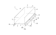
- FIG. 1 is a perspective view showing a sway reduction device and a floating body including the same according to each embodiment of the present invention.
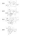
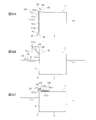
- 2A to 2D are cross-sectional views of the floating body for explaining the operation principle of the fluctuation reducing device according to each embodiment of the present invention, and FIG. 2A is a diagram for explaining the fluctuation of the floating body not equipped with the present apparatus.
- FIG. 2D is a diagram for explaining the operating principle of this apparatus.
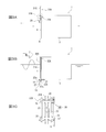
- 3A to 3C are views showing the configuration of the sway reduction device according to the first embodiment of the present invention, and FIG. 3A is a cross-sectional view of the floating body showing a state in which the fin (plate portion) is in the lifting position.
- FIG. 3B is a cross-sectional view of the floating body showing a state where the fin is in the use position
- FIG. 3C is an enlarged view showing the moving mechanism.
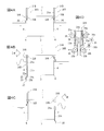
- 4A to 4C are views showing the configuration of the fluctuation reducing device according to the second embodiment of the present invention
- FIG. 4A is a cross-sectional view of a floating body showing a state where fins (plate portions) are in the lifting position
- 4B and 4C are cross-sectional views of the floating body showing a state where the fin is in the use position
- FIG. 4D is an enlarged view showing the moving mechanism.
- 5A to 5C are diagrams showing the configuration of the fluctuation reducing device according to the third embodiment of the present invention
- FIG. 5A is a cross-sectional view of a floating body showing a state where fins (plate portions) are in a use position.
- 5B is a cross-sectional view of the floating body showing a state in which the fin is moving to the lifting position
- FIG. 5C is a cross-sectional view of the floating body showing a state where the fin is in the lifting position. It is sectional drawing explaining the shape of the fin (plate part) concerning each embodiment. It is sectional drawing explaining the modification of the movable mechanism concerning 1st, 2 embodiment.
- the vertical upper direction is the upper or upper direction
- the vertical lower side is the lower or lower direction
- the direction toward the center line of the center in the width direction of the floating body is the inner side or the inner side.
- the direction away from the center line will be described as outward or outward.
- FIG. 1 is a perspective view showing a floating body (floating structure) equipped with the fluctuation reducing device according to each embodiment.
- a floating body 1 is a box-shaped (substantially rectangular parallelepiped) having an upper surface portion (upper surface) 2, a lower surface portion (lower surface) 3, both side surface portions (side surfaces) 4, 4, and both end surface portions (end surfaces) 5, 5.
- the shake reduction apparatus 10 is equipped with only one side part 4, or in addition to both or one side part 4 You may equip both or one end surface part 5.
- the sway reduction device 10 includes a fin (plate part) 20, and the fin 20 is supported by a support unit coupled to the floating body 1 although not shown in FIG. Has been.
- the fin 20 is arranged at the corner 6 between the side surface 4 and the bottom surface 3 of the floating body 1 with the base end 21 opened from the corner 6 with a gap 7 therebetween, and the tip end protrudes toward the lateral outer side of the floating body 1. Used in the state.
- the fin 20 is inclined from the vicinity of the corner 6 to the outside of the side surface 4 of the floating body 1 and obliquely downward at the use position, and is bent from the tip of the inclined portion 22 and extends vertically downward. And a vertical portion 23.
- An upward surface 22a of the fin 20 collects a water flow entering from the outside of the side surface 4 toward the side surface 4 by a wave pushing wave toward the gap 7. It functions as a guide surface for guiding.
- the size of the gap 7 is such that the water flow guided by the upward surface 22 a of the fin 20 and entering just below the bottom surface 3 from the gap 7 forms a high-speed laminar flow in the region near the corner 6 of the bottom surface 3. It is preferable to set it small.
- the downward surface of the fin 20 (that is, the downward surface facing the obliquely inner side of the inclined portion 22) 22b and the inward surface 23b of the vertical portion 23 flow outward from the bottom surface 3 due to wave pulling waves. It functions as a resistance surface that prevents
- FIG. 2A when a pressing wave is pushed toward the side surface 4 from the side [left side in FIG. 2A], a clockwise wave forcing moment M1 is applied to the floating body 1 as indicated by the white arrow in FIG. If the fluctuation reducing device 10 is not provided, the floating body 1 will roll.
- the guide surface 22 a of the fin 20 collects the water flow that enters the side surface 4 from the outside of the side surface 4 due to the pushing waves of the waves. Then, it guides toward the gap 7 between the base 21 and the corner 6 of the fin 20 (see FIG. 2D). Since the water stream gathers in the gap 7 as shown by a single-line arrow and increases the speed and enters the gap immediately below the bottom surface 3 from the gap 7, the water stream flows along the bottom surface 3 while forming a high-speed laminar flow.
- the resistance surface 22b, 23b of the fin 20 becomes a resistance to block this water flow against the water flow that advances outward from the bottom surface 3 due to the wave pulling wave.
- the resistance surfaces 22b and 23b are pressed, and a force F2 that pushes the bottom surface 3 upward acts on the floating body 1 under the bottom surface 3 near the corner 6 (see FIG. 2D).
- the counterclockwise wave forcing force moment M2 is applied to the floating body 1 by the pulling wave, since the force F2 acts so as to cancel the wave forcing force moment M2, the fluctuation of the floating body 1 due to the pulling wave is suppressed. .
- the sway reduction device 10 uses a guide surface 22a of the fin 20 to prevent the water flow WF1 entering from the outside of the side surface 4 toward the side surface 4 due to the pushing waves of the waves.
- the water flow WF1 is collected and guided from the gap 7 directly below the bottom surface 3, and the resistance surface 22b, 23b of the fin 20 is against the water flow WF2 that is going to move outward from the bottom surface 3 due to the wave drawing. This prevents the water flow WF2 from flowing out from the gap 7.
- Each of the following embodiments is a fluctuation reducing device having the fin 20 that reduces the fluctuation of the floating body 1 in this way, but the fin 20 is movable between a use position below the water surface and a pulling position on the water surface. It is characterized in that it is configured.
- the fluctuation reduction device 10A according to the first embodiment of the present invention will be described.
- the fluctuation reducing device 10 ⁇ / b> A is provided only on the side surface 4 on one side of the floating body 1, and includes a fin 20 and a support 30 ⁇ / b> A that is coupled to the floating body 1 and supports the fin 20.
- the floating body 1 is used by being moored by arranging the side surface 4 on one side equipped with the vibration reduction device 10 ⁇ / b> A in the direction of the open ocean where waves enter.
- the fin 20 has, in the use position, an inclined portion 22 that extends obliquely downward outside the side surface 4 of the floating body 1 from the vicinity of the corner portion 6, and bends from the tip of the inclined portion 22 and extends vertically downward. And an extended vertical portion 23.
- the upward surface 22a of the inclined portion 22 of the fin 20 functions as a guide surface that collects the water flow entering from the outside of the side surface 4 toward the side surface 4 by the wave pushing waves and guides it toward the gap 7 (see FIG. 1).
- the downward surface 22b of the inclined portion 22 of the fin 20 and the inward surface 23b of the vertical portion 23 function as a resistance surface that prevents a water flow that advances outward from the bottom surface 3 due to the wave pulling.
- the fins 20 extend in the longitudinal direction of the floating body 1 (the direction in which the corners 6 extend), and the length is set so as to cover the entire length in the longitudinal direction of the floating body 1 or substantially the entire length.
- the fins 20 are supported by the support portion 30A at a plurality of locations in the longitudinal direction, for example, at three locations near both ends and an intermediate portion, or at a plurality of locations near both ends and an intermediate portion.
- the fin 20 is one piece having a length over the entire length of the floating body 1 or substantially the entire length, but the fin 20 is divided into a plurality of portions in the longitudinal direction, and each of them is supported by the support portion 30A in the same manner as described above. You may support.
- the support portion 30A includes a support arm 31A to which the fin 20 is fixed, and a movable mechanism 32A that moves the support arm 31A to move the fin 20 between a use position below the water surface and a pull-up position on the water surface. is doing.
- the support arm 31A has one length substantially along the height of the floating body 1, is arranged in the vertical direction, has the fin 20 fixed to the lower end portion, and is driven up and down by the movable mechanism 32A.
- the movable mechanism 32A is supported by a rack (linear tooth row) 33 provided along the axial direction on the support arm 31A and an upper portion of the floating body 1 (here, an upper portion of the side surface 4).
- the drive pinion 34 meshes with the rack 33, a guide pinion (guide member) 35, and a motor 36 that rotationally drives the drive pinion 34.
- the drive pinion 34 and the guide pinion 35 are supported on the upper part of the side surface 4 via a bracket 37.
- the motor 36 an electric motor or a hydraulic motor can be used as appropriate.
- racks 33 are provided in parallel and back-to-back on the outside and inside of the support arm 31A, respectively, and a drive pinion 34 and one guide pinion 35 are lined up and down, and one (here, the inside) rack 33 is arranged.
- the two guide pinions 35 and 35 are arranged vertically so as to face the inner drive pinion 34 and the guide pinion 35, and engage with the other (here, the outer) rack 33. Is arranged.
- the rack 33 can be moved up and down and the support arm 31A can be moved up and down.
- the guide pinion 35 guides the support arm 31 ⁇ / b> A so as to be slidable in the vertical direction so that the support arm 31 ⁇ / b> A moves up and down while maintaining the vertical posture while being rotated following the movement of the rack 33.
- the motor 36 has a built-in brake that restricts rotation, and this brake functions as a holding mechanism that holds the positions of the support arm 31A and the fin 20 in the vertical movement direction.
- the movable mechanism 32A is operated to support the arm 31A. Is moved downward in the vertical direction, the fin 20 is set at a predetermined use position below the water surface, and the brake of the motor 36 is operated to fix the support arm 31A. Thereby, it can set to a use position easily and also can obtain the rocking
- the fin 20 in the use position protrudes toward the outside of the side surface 4, it interferes with the berthing, but when the berthing is made, the fin 20 can be lifted onto the water surface, so that the floating body 1 can be berthed without any trouble.
- the lifting position of the fin 20 is higher than the assumed height of the quay.
- the fluctuation reducing device 10A is equipped only on the side surface 4 on one side of the floating body 1, the installation cost of the fluctuation reducing device 10A can be suppressed.
- the side surface 4 on both sides of the floating body 1 may be equipped with the sway reduction device 10A, respectively, so that any side surface 4 of the floating body 1 can be used toward the offshore side.
- the support arm 31A may be guided so as to be slidable in the vertical direction instead of a roller that contacts a portion of the support arm 31A where the rack 33 is not formed.
- the holding mechanism for holding the fin 20 at the use position and the pull-up position may use an individual mechanical stopper or the like.
- the sway reduction device 10B differs from the first embodiment in a part of the configuration of the support portion 30B, and the other configurations are configured substantially the same as in the first embodiment. Therefore, the same components as those in the first embodiment will be described with reference to the same reference numerals as those in the first embodiment, and the description thereof will be omitted. The differences from the first embodiment will be mainly described.
- the fluctuation reducing device 10B is mounted on each of the side surfaces 4 on both sides of the floating body 1, and is coupled to the fin 20 and the floating body 1 to form the fins.
- a support portion 30 ⁇ / b> B that supports 20.
- the fin 20 is inclined from the vicinity of the corner portion 6 to the outside of the side surface 4 of the floating body 1 and obliquely downward at the use position, and is bent from the tip of the inclined portion 22 and extends vertically downward.
- a vertical portion 23 is described above.
- the support portion 30B includes a support arm 31B to which the fin 20 is fixed, and a movable mechanism 32B that moves the support arm 31B to move the fin 20 between a use position below the water surface and a pull-up position on the water surface. is doing.
- the support arm 31B and the movable mechanism 32B are different from those of the first embodiment.
- the support arm 31B of the present embodiment includes a first arm part 31a and a second arm part 31b that are connected to be extendable and a telescopic mechanism 38 that extends and contracts the first arm part 31a and the second arm part 31b. is doing.
- the length is approximately along the height of the floating body 1 like the support arm 31A of the first embodiment.
- first arm portion 31a is formed in a hollow shape, and the second arm portion 31b can be accommodated in the hollow inside of the first arm portion 31a.
- the lower end inner periphery of the hollow portion of the first arm portion 31a is reduced in diameter
- the upper end outer periphery of the second arm portion 31b is increased in diameter
- the second arm portion 31b is on the extension side with respect to the first arm portion 31a.
- the reduced diameter portion and the enlarged diameter portion engage and fit to function as a holding mechanism that fixes the second arm portion 31b in the extended state.
- the movable mechanism 32B is provided along the axial direction on the rack (linear tooth row) 33a provided on the first arm portion 31a along the axial direction and on the second arm portion 31b.
- the drive pinion 34a and the guide pinion (guide member) 35 which are supported by the rack (straight tooth row) 33b, the upper part of the floating body 1 (upper part of the side surface 4) and mesh with the rack 33a, and the drive pinion 34a are driven to rotate Motor 36a, a drive pinion 34b and a guide pinion 35 that mesh with the rack 33b, and a motor 36b that rotationally drives the drive pinion 34b.
- the guide pinion 35 may further provide the guide pinion 35 arrange
- the rotation of the motor 36a is fixed, the movement of the first arm portion 31a is restricted, and the motor 36b is operated to move the second arm portion 31b.
- the expansion / contraction mechanism 38 is connected to each rack and pinion mechanism. And these motors 36a and 36b.
- the drive pinions 34a and 34b and the guide pinion 35 are supported on the upper portion of the side surface 4 via a bracket (not shown).
- the drive pinion 34b that meshes with the rack 33b of the second arm portion 31b and the guide pinion 35 that opposes the drive pinion 34b are separated by a separation mechanism (not shown) with respect to the second arm portion 31b, as indicated by a horizontal arrow in FIG. 4D.
- the drive pinion 34b and the guide pinion 35 are appropriately separated from the second arm portion 31b.
- the racks 33a and 33b can be moved up and down to raise and lower the support arm 31B.
- the motor 36a is fixed by a brake, and the motor 36b is operated to lower the second arm portion 31b.
- the second arm portion 31b moves to the extension side with respect to the first arm portion 31a, the reduced diameter portion and the enlarged diameter portion are fitted, and the second arm portion 31b is held in the extended state.
- the drive pinion 34b and the guide pinion 35 meshing with the rack 33b are separated from the second arm portion 31b, and the motor 36a is operated to lower the first arm portion 31a.
- the brake of the motor 36a is operated to fix the support arm 31B. To do.
- the motor 36a is operated with the drive pinion 34b and the guide pinion 35 meshing with the rack 33b being separated from the second arm portion 31b, so that the first arm portion is operated. 31a is raised.
- the second arm portion 31b fixed in the extended state together with the first arm portion 31a rises, and the rack 33b of the second arm portion 31b rises to the position of the drive pinion 34b and the guide pinion 35, the drive pinion 34b
- the motor 36a is fixed by a brake, and the motor 36b is operated to raise the second arm portion 31b.
- the torque of the motor 36b releases the fit between the reduced diameter portion and the enlarged diameter portion, and the second arm portion 31b becomes movable, and moves toward the contraction side with respect to the first arm portion 31a.
- the brake of the motor 36b is operated to fix the support arm 31B.
- the fluctuation reducing device 10B according to the second embodiment of the present invention is configured as described above, as in the first embodiment, as shown in FIG. 4B or FIG. Can be easily set at a predetermined use position below the surface of the water, and the motion reduction effect of the floating body 1 by the motion reduction device 10B having the fins 20 can be obtained.
- the movable mechanism 32B When towing the floating body 1 or bringing it into the berth, as shown in FIG. 4A, the movable mechanism 32B is operated to move the support arm 31B upward in the vertical direction, and the fin 20 is lifted on the water surface. And the brakes of the motors 36a and 36b are operated to fix the support arm 31B. Thereby, when the floating body 1 is towed, the floating body 1 can be smoothly towed without causing deterioration in fuel consumption, and when the floating body 1 is berthed, the floating body 1 can be pierced without any trouble.
- the sway reduction device 10B is installed on the side surfaces 4 and 4 on both sides of the floating body 1.
- the sway reduction device 10B is provided only on the side surface 4 on one side of the floating body 1. May be installed.
- the sway reduction device 10C according to the third embodiment of the present invention will be described.
- the fluctuation reducing device 10C is different from the first embodiment in the configuration of the support unit 130, and the other configurations are substantially the same as those in the first embodiment. Therefore, the same components as those in the first embodiment will be described with reference to the same reference numerals as those in the first embodiment, and the description thereof will be omitted. The differences from the first embodiment will be mainly described.
- the fluctuation reducing device 10C is provided only on the side surface 4 on one side of the floating body 1, and is coupled with the fin 20 and the floating body 1 to the fins. 20 and a support portion 130 that supports 20.
- the fin 20 is inclined from the vicinity of the corner portion 6 to the outside of the side surface 4 of the floating body 1 and obliquely downward at the use position, and is bent from the tip of the inclined portion 22 and extends vertically downward. And a vertical portion 23.
- the support arm 131 is pivotally supported at the upper part of the floating body 1 at the base end, and the fin 20 is fixed to the distal end portion of the support arm 131.
- a movable mechanism 132 for turning the support arm 131 is also provided.
- the movable mechanism 132 is between a state in which the tip of the support arm 131 is directed in the vertical direction and the fin 20 is in the use position, and a state in which the support arm 131 is pulled up to the top of the floating body 1 and the fin 20 is in the lift position.
- An actuator 136 for rotating the support arm 131 is provided.
- the support arm 131 includes a first arm portion 131a and a second arm portion 131b that are coupled to each other by a coupling portion 131c so that the first arm portion 131a and the second arm portion 131b are coupled to each other.
- a lock mechanism (not shown) is provided that fixes the extended state to the extended state.
- the fin 20 is fixed to a distal end portion that is a free end (an end not on the coupling portion 131c side) of the second arm portion 131b, and an actuator 136 is mounted on a proximal end portion 131d that is a free end side of the first arm portion 131a.
- the actuator 136 a hydraulic actuator, an electric actuator, or the like can be used as appropriate.
- the actuator 136 When setting the fin 20 to the use position, the actuator 136 is actuated so that the end of the first arm portion 131a on the coupling portion 131c side is turned vertically downward, and as shown in FIG. The first arm portion 131a and the second arm portion 131b are fixed in an extended state by operating. Further, the actuator 136 is brought into a locked state.
- the lock mechanism When setting the fin 20 from the use position to the lifting position, the lock mechanism is released so that the first arm portion 131a and the second arm portion 131b can be bent.
- the actuator 136 As shown in FIG. 5B, the actuator 136 is actuated so that the end of the first arm portion 131a on the coupling portion 131c side is turned up, and the end portion of the first arm portion 131a on the coupling portion 131c side is further turned.
- the actuator 136 is brought into a locked state by pulling it up to the upper surface portion 2 of the floating body 1 while turning the floating body 1 upward.
- the fluctuation reducing device 10C according to the third embodiment of the present invention is configured as described above, as in the first embodiment, as shown in FIG. Therefore, it is possible to obtain the motion reduction effect of the floating body 1 by the motion reduction device 10 ⁇ / b> C having the fins 20.
- the movable mechanism 132 When towing the floating body 1 or bringing it into the berth, as shown in FIG. 5C, the movable mechanism 132 is operated and the support arm 131 is pulled up by the actuator 136, and the fin 20 is set at the lifting position on the water surface. Then, the actuator 136 is fixed. Thereby, when the floating body 1 is towed, the floating body 1 can be smoothly towed without causing deterioration in fuel consumption, and when the floating body 1 is berthed, the floating body 1 can be pierced without any trouble.
- the vibration reduction device 10C is installed only on the side surface 4 on one side of the floating body 1. However, as in the second embodiment, the vibration reduction device 10C is installed in the floating body 1. You may install in the side surfaces 4 and 4 of both sides.
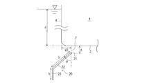
- FIG. 6 is a cross-sectional view of the fin 20 according to each embodiment in use. As described above, in the use position, the fin 20 is inclined from the vicinity of the corner portion 6 and extends obliquely downward outside the side surface 4 of the floating body 1 and is bent from the tip of the inclined portion 22 and extends vertically downward. And a vertical portion 23.
- the depth from the water surface of the bottom surface 3 of the floating body 1 is d
- the vertical position of the base end 21 of the fin 20 with respect to the floating body 1 is s
- the value with the downward direction being positive with respect to the bottom surface 3 of the floating body 1
- the fin 20 The horizontal direction position of the base end 21 of the floating body 1 with respect to the side surface 4 of the floating body 1 is x0 with the center direction of the floating body 1 being positive
- the length of the inclined portion 22 is b
- the inclined angle of the inclined portion 22 with respect to the vertical Is ⁇ and the length of the vertical portion 23 is h.
- the shape and arrangement as shown in Table 1 are preferable.
- the parameter x0 cannot be set to a value of 0 or more in order to avoid interference with the side surface 4. Therefore, in consideration of this, in the case of the first and second embodiments, in addition to the mechanism for vertically moving the fin 20, as shown by a two-dot chain line in FIG. 20 or a mechanism for shifting the support portions 30A, 30B toward the center of the floating body can be used to achieve the optimum state.
- the fin is used with at least the base end being spaced from the corner of the floating body and protruding toward the outside of the side surface of the floating body.
- the upward surface of the fin is It functions as a guide surface that collects the water flow that tries to enter the side from the outside of the side and guides it toward the gap, and the downward surface of the fin is a water flow that tries to advance from the bottom to the outside due to wave pulling waves. Any material may be used as long as it functions as a resistance surface that prevents the above.
Landscapes
- Engineering & Computer Science (AREA)
- Theoretical Computer Science (AREA)
- General Engineering & Computer Science (AREA)
- Physics & Mathematics (AREA)
- General Physics & Mathematics (AREA)
- Human Computer Interaction (AREA)
- Bridges Or Land Bridges (AREA)
- Other Liquid Machine Or Engine Such As Wave Power Use (AREA)
- Facsimiles In General (AREA)
Abstract
簡素な構造で確実に浮体の動揺低減効果を得られ、浮体を曳航する際の抵抗増を抑制し接岸にも支障のないようにした、動揺低減装置を提供する。 浮体(1)の側面(4)と底面(3)との角部(6)に隙間(7)を開けて配置され、浮体(1)の側面(4)の外側に向けて突出させた状態で使用される板部(20)と、板部(20)を支持する支持部(30A)と、を有し、板部(20)の上向き面(22a)は波浪の押し波によって側面(4)の外方から側面(4)に進入する水流を集めて隙間(7)に向けて案内し、板部(20)の下向き面(22b)は波浪の引き波によって底面(3)から外方へ向けて進出する水流を阻止し、支持部(30A)は、板部(20)が固定された支持アーム(31A)と、支持アーム(31)を移動させて板部(20)を水面下の使用位置と水面上の引き上げ位置との間で移動させる可動機構(32A)とを有する。
Description
本発明は、浮体に装備される動揺低減装置及びこれを備えた浮体に関するものである。
近年、海洋,湖沼,河川等の水上の設備として、浮体構造物(以下、単に浮体とも言う)が広く適用されている。こうした浮体には、例えば、各種作業船,ドリルシップ,石油生産プラットフォーム,浮桟橋,浮倉庫,浮駐車場などがある。浮体は、水底に支柱を設置する必要がないので構造を簡素化できる反面、浮体に対して波浪が入射して動揺してしまうことから、この浮体の動揺を低減する必要がある。
浮体の波浪中における横揺れは、波浪によって生じる波強制力モーメントで誘起される。通常の浮体では、横揺れ方向の運動に対して十分な減衰を確保することが難しいため、固有周期近傍の波周期では揺れの振幅が大きくなる。そこで、従来から、浮体の動揺を低減する様々な技術が提案されている(例えば、特許文献1~特許文献4)。
特許文献1には、板を海底から所定距離以内に吊り下げ、板に作用する流体力によって、付加質量及び粘性減衰力の増大を期待して動揺低減を図ろうとする技術が記載されている。
特許文献2には、浮体の波の入射側側面に、波の進行方向上流側に向け傾斜し浮体の喫水線付近から下面深さ付近まで至らせた傾斜板を付設し、傾斜面による動揺低減を図ろうとする技術が記載されている。
特許文献2には、浮体の波の入射側側面に、波の進行方向上流側に向け傾斜し浮体の喫水線付近から下面深さ付近まで至らせた傾斜板を付設し、傾斜面による動揺低減を図ろうとする技術が記載されている。
特許文献3には、波の入射側の側部下端に、浮体の底面より下方に延びる鉛直板を、浮体と通水可能な間隔をあけて配置し、鉛直板を傾動可能とし、鉛直板の傾動により動揺低減を図ろうとする技術が記載されている。
特許文献4には、箱形浮体の長さと幅との比に対し、箱形浮体の幅と吃水との比の設定により、波力の影響を小さくして動揺低減を図ろうとする技術が記載されている。
特許文献4には、箱形浮体の長さと幅との比に対し、箱形浮体の幅と吃水との比の設定により、波力の影響を小さくして動揺低減を図ろうとする技術が記載されている。
しかしながら、特許文献1の技術では、洋上での動揺低減装置の設営作業が容易ではない。特許文献2の技術では、浮体の喫水線の部分よりも側面下部が突出するので、浮体の接岸時に、突出部が浮体の喫水線付近の接岸の妨げになるおそれがある。特許文献3の技術では、鉛直板が浮体を曳航する際に抵抗体として作用するおそれがある。また、特許文献1~3の技術では、いずれも動揺低減装置が大型になり易い。特許文献4の技術では、浮体の形状自体の設定自由度が低下してしまう。
本発明は、かかる課題を解決しようとするもので、装置の大型化を招くことなく、簡素な構造で確実に浮体の動揺低減効果を得られ、しかも、浮体を曳航する際の抵抗増を抑制し、接岸にも支障のないようにした、動揺低減装置及びこれを備えた浮体を提供することを目的としている。
(1)上記の目的を達成するために、本発明の動揺低減装置は、浮体の側面と底面との角部に、基端を前記角部から隙間を開けて配置され、先端寄りを前記浮体の側面の外側に向けて突出させた状態で使用される板部と、前記浮体に結合され前記板部を支持する支持部と、を有し、前記板部の上向き面は、波浪の押し波によって前記側面の外方から前記側面に進入しようとする水流を集めて前記隙間に向けて案内する案内面として機能し、前記板部の下向き面は、波浪の引き波によって前記底面から前記外方へ向けて進出しようとする水流を阻止する抵抗面として機能し、前記支持部は、前記板部が固定された支持アームと、前記支持アームを移動させて前記板部を水面下の使用位置と水面上の引き上げ位置との間で移動させる可動機構とを有することを特徴としている。
(2)前記支持部は、前記板部を前記使用位置及び前記引き上げ位置にそれぞれ保持する保持機構を有することが好ましい。
(3)前記板部は、鉛直方向に配置された前記支持アームの下端部に固定され、前記可動機構は、前記支持アームに軸方向に沿って設けられたラックと、前記浮体の上部に支持され前記ラックと噛合する駆動ピニオンと、前記支持アームを鉛直方向にスライド可能にガイドするガイド部材と、前記駆動ピニオンを回転駆動するモータと、を有することが好ましい。
(4)前記支持アームは、伸縮可能に結合された第1アーム部及び第2アーム部と、前記第1アーム部と前記第2アーム部とを伸縮させる伸縮機構と、を有し、前記板部は前記第2アーム部の下端部に固定され、前記第1アーム部に前記ラックが形成され、前記板部を前記使用位置にする際は、前記伸縮機構を作動させて前記第2アーム部を前記第1アーム部から下方に伸張させると共に、前記モータを作動させて前記第1アーム部を下降させることが好ましい。
(5)前記板部は前記支持アームの先端部に固定され、前記支持アームの基端は前記浮体の上部に旋回可能に支持され、前記可動機構は、前記支持アームの先端部を鉛直方向に向けて前記板部を前記使用位置とする状態と、前記支持アームを前記浮体の上部に引き上げて前記板部を前記引き上げ位置とする状態との間で、前記支持アームを旋回させるアクチュエータを有することが好ましい。
(6)前記支持アームは、結合部で互いに屈伸可能に結合された第1アーム部及び第2アーム部と、前記第1アーム部と前記第2アーム部との伸張時に伸張状態に固定するロック機構と、を有し、前記板部は前記第2アーム部の自由端側である先端部に固定され、前記第1アーム部の自由端側である基端部に前記アクチュエータが装備され、前記板部を前記使用位置にする際は、前記アクチュエータを作動させて前記第1アーム部の前記結合部側の端部が鉛直下方に向くように旋回させ、前記ロック機構を作動させて前記第1アーム部と前記第2アーム部とを伸張状態に固定することが好ましい。
(7)前記板部の基部と前記角部との前記隙間の大きさは、前記板部の上向き面により案内され前記隙間から前記底面に進入した水流が、前記底面の前記角部の近傍領域で高速層流を形成するように小さく設定されていることが好ましい。
(8)前記板部は、前記使用位置において、前記角部の近傍から前記浮体の側面の外側の斜め下方に延びた傾斜部を有することが好ましい。
(9)前記板部は、前記使用位置において、前記傾斜部と、前記傾斜部から屈曲し鉛直下方に延びた鉛直部とを有することが好ましい。
(10)前記板部は、前記浮体の前記側面の全長に亘って設置されていることが好ましい。
(11)本発明の浮体は、側面と底面との角部を有し、前記角部に、上記の動揺低減装置を装備されていることを特徴とする。
(12)前記動揺低減装置が、前記浮体の両側の前記側面にそれぞれ設置されていることが好ましい。
本発明の動揺低減装置によれば、板部の上向き面が案内面として機能して、波浪の押し波によって浮体の側面の外方から側面に進入する水流を集めて、板部の基部と角部との隙間に向けて案内するので、水流が隙間に集合しながら速度を速めて隙間から底面の直下に進入する。水流は高速で底面に沿って流れるので、角部近傍の底面の下部には負圧が作用して、角部近傍の底面を下方に引き下げるように浮体に作用する。押し波は浮体に対して側面を上昇させるように作用するが、上記負圧がこれを相殺するように浮体に作用するので、押し波による浮体の動揺が抑制される。
また、板部の下向き面が抵抗面として機能して、波浪の引き波によって底面から外方へ向けて進出する水流を阻止するので、水流が抵抗面を押圧して、角部近傍の底面を上方に押し上げるように浮体に作用する。引き波は浮体に対して側面を下降させるように作用するが、上記水流による抵抗面を押圧する力がこれを相殺するように浮体に作用するので、引き波による浮体の動揺が抑制される。
また、可動機構によって、板部を水面下の使用位置に容易に設定することができ、さらにこの使用位置から水面上の引き上げ位置へと移動させることができるので、浮体の曳航時には、板部を水面上へ引き上げて、板部が抵抗体として作用しないようにすることができ、浮体を円滑に且つ燃費の悪化を招くことなく曳航することができる。また、使用位置の板部は側面の外側に向けて突出させているので接岸の妨げになるが、板部を水面上へ引き上げることで支障なく浮体を接岸させることができる。
以下、図面を参照して、本発明の実施の形態を説明する。
なお、以下の説明では、鉛直上方を上又は上方とし、鉛直下方を下又は下方とし、浮体の側面において、浮体の幅方向中央の中心線に向く方向を内方又は内側とし、その反対側、中心線から離れる方向を外方又は外側として説明する。
なお、以下の説明では、鉛直上方を上又は上方とし、鉛直下方を下又は下方とし、浮体の側面において、浮体の幅方向中央の中心線に向く方向を内方又は内側とし、その反対側、中心線から離れる方向を外方又は外側として説明する。
また、以下に示す各実施形態はあくまでも例示に過ぎず、以下の実施形態で明示しない種々の変形や技術の適用を排除する意図はない。以下の実施形態の各構成は、それらの趣旨を逸脱しない範囲で種々変形して実施することができるとともに、必要に応じて取捨選択することができ、あるいは適宜組み合わせることが可能である。
〔動揺低減装置の概要〕
まず、図1,図2(図2A~図2D)を参照して各実施形態にかかる動揺低減装置の概要を説明する。
図1は、各実施形態にかかる動揺低減装置を装備した浮体(浮体構造物)を示す斜視図である。図1に示すように、浮体1は、上面部(上面)2,下面部(下面)3,両側面部(側面)4,4,及び両端面部(端面)5,5を有する箱型(ほぼ直方体)に形成されている。ここでは、両側面部4,4に動揺低減装置10を装備した例を示しているが、動揺低減装置10を、一方の側面部4のみに装備したり、両方又は一方の側面部4に加えて両方又は一方の端面部5に装備したりしてもよい。
まず、図1,図2(図2A~図2D)を参照して各実施形態にかかる動揺低減装置の概要を説明する。
図1は、各実施形態にかかる動揺低減装置を装備した浮体(浮体構造物)を示す斜視図である。図1に示すように、浮体1は、上面部(上面)2,下面部(下面)3,両側面部(側面)4,4,及び両端面部(端面)5,5を有する箱型(ほぼ直方体)に形成されている。ここでは、両側面部4,4に動揺低減装置10を装備した例を示しているが、動揺低減装置10を、一方の側面部4のみに装備したり、両方又は一方の側面部4に加えて両方又は一方の端面部5に装備したりしてもよい。
図1,図2A~図2Dに示すように、動揺低減装置10は、フィン(板部)20を備え、このフィン20は、図1では省略するが、浮体1に結合された支持部によって支持されている。このフィン20は、浮体1の側面4と底面3との角部6に、基端21を角部6から隙間7を開けて配置され、先端寄りを浮体1の側方外側に向けて突出させた状態で使用される。
各実施形態では、フィン20は、その使用位置において、角部6の近傍から浮体1の側面4の外側の斜め下方に延びた傾斜部22と、傾斜部22の先端から屈曲し鉛直下方に延びた鉛直部23とを有している。
フィン20の上向き面(即ち、傾斜部22の斜め外側に向いた上向き面)22aは、波浪の押し波によって側面4の外方から側面4に向かって進入する水流を集めて隙間7に向けて案内する案内面として機能する。
このため、隙間7の大きさは、フィン20の上向き面22aにより案内され隙間7から底面3の直下に進入した水流が、底面3の角部6の近傍領域で高速層流を形成するように小さく設定されていることが好ましい。
また、フィン20の下向き面(即ち、傾斜部22の斜め内側に向いた下向き面)22bと鉛直部23の内向き面23bは、波浪の引き波によって底面3から外方へ向けて進出する水流を阻止する抵抗面として機能する。
例えば図2Aにおいて、側方[図2A中、左方]から側面4に押し波が押し寄せると、図2A中に示す白抜き矢印のように、時計回りの波強制力モーメントM1が浮体1に加えられ、動揺低減装置10を備えなければ浮体1に横揺れが生じる。
これに対して、図2Bに示すように、浮体1に動揺低減装置10を装備すると、フィン20の案内面22aが、波浪の押し波によって側面4の外方から側面4に進入する水流を集めて、フィン20の基部21と角部6との隙間7に向けて案内する(図2D参照)。水流は、一本線矢印で示すように隙間7に集合しながら速度を速めて隙間7から底面3の直下に進入するので、水流は高速の層流を形成しながら底面3に沿って流れる。これにより、角部6近傍の底面3の下部には負圧が作用して、角部6近傍の底面3を下方に引き下げる力F1が浮体1に作用する。この力F1が波強制力モーメントM1を相殺するように作用するので、押し波による浮体1の動揺が抑制される。
また、図2Cに示すように、波浪の引き波によって底面3から外方へ向けて進出する水流に対しては、フィン20の抵抗面22b,23bがこの水流を阻止する抵抗となるので、水流が、一本線矢印で示すように抵抗面22b,23bを押圧して、角部6近傍(図2D参照)の底面3の下方が高圧になり底面3を上方に押し上げる力F2が浮体1に作用する。浮体1には、引き波により反時計回りの波強制力モーメントM2が加えられるが、力F2が波強制力モーメントM2を相殺するように作用するので、引き波による浮体1の動揺が抑制される。
すなわち、動揺低減装置10は、図2Dに示すように、波浪の押し波によって側面4の外方から側面4に向けて進入しようとする水流WF1に対しては、フィン20の案内面22aによってこの水流WF1を集めて隙間7から底面3の直下に向けて案内し、波浪の引き波によって底面3から外方へ向けて進出しようとする水流WF2に対しては、フィン20の抵抗面22b,23bによってこの水流WF2の隙間7からの流出を阻止する。
このようにして、押し波に対しても引き波に対しても各波強制力モーメントM1,M2を打ち消すように水流による力F1,F2が作用し、浮体1の動揺が低減される。
以下の各実施形態は、何れも、このように浮体1の動揺を低減するフィン20を有する動揺低減装置であるが、フィン20が水面下の使用位置と水面上の引き上げ位置との間で可動に構成されている点に特徴がある。
以下の各実施形態は、何れも、このように浮体1の動揺を低減するフィン20を有する動揺低減装置であるが、フィン20が水面下の使用位置と水面上の引き上げ位置との間で可動に構成されている点に特徴がある。
〔第1実施形態〕
まず、本発明の第1実施形態にかかる動揺低減装置10Aを説明する。この動揺低減装置10Aは、図3A,図3Bに示すように、浮体1の片側の側面4にのみ装備されており、フィン20と、浮体1に結合されてフィン20を支持する支持部30Aとを有している。なお、浮体1は動揺低減装置10Aを装備される片側の側面4を波浪が進入してくる外洋向きに配置して係留されて使用される。
まず、本発明の第1実施形態にかかる動揺低減装置10Aを説明する。この動揺低減装置10Aは、図3A,図3Bに示すように、浮体1の片側の側面4にのみ装備されており、フィン20と、浮体1に結合されてフィン20を支持する支持部30Aとを有している。なお、浮体1は動揺低減装置10Aを装備される片側の側面4を波浪が進入してくる外洋向きに配置して係留されて使用される。
フィン20は、上述の説明のように、使用位置において、角部6の近傍から浮体1の側面4の外側の斜め下方に延びた傾斜部22と、傾斜部22の先端から屈曲し鉛直下方に延びた鉛直部23とを有している。
フィン20の傾斜部22の上向き面22aは、波浪の押し波によって側面4の外方から側面4に向かって進入する水流を集めて隙間7(図1参照)に向けて案内する案内面として機能し、フィン20の傾斜部22の下向き面22b及び鉛直部23の内向き面23bは、波浪の引き波によって底面3から外方へ向けて進出する水流を阻止する抵抗面として機能する。
このフィン20は、浮体1の長手方向(角部6の延びる方向)に延在し、浮体1の長手方向の全長又は略全長にわたるように長さを設定されている。フィン20は、長手方向の複数箇所で、例えば両端部近傍と中間部との3箇所で、或いは、両端部近傍と中間部の複数箇所で、支持部30Aによって支持されている。ここでは、フィン20は、浮体1の全長又は略全長にわたる長さの一本のものとしているが、フィン20を長手方向に複数に分割して構成し、それぞれ、支持部30Aによって上記と同様に支持してもよい。
支持部30Aは、フィン20が固定された支持アーム31Aと、この支持アーム31Aを移動させてフィン20を水面下の使用位置と水面上の引き上げ位置との間で移動させる可動機構32Aとを有している。ここでは、支持アーム31Aは浮体1の高さにほぼ沿った長さの一本のものとしており、鉛直方向に向けて配置され、下端部にフィン20を固定され、可動機構32Aによって昇降駆動される。
可動機構32Aは、図3Cに示すように、支持アーム31Aに軸方向に沿って設けられたラック(直線状の歯列)33と、浮体1の上部(ここでは、側面4の上部)に支持され、ラック33と噛合する駆動ピニオン34,ガイドピニオン(ガイド部材)35と、駆動ピニオン34を回転駆動するモータ36と、を有している。駆動ピニオン34及びガイドピニオン35はブラケット37を介して側面4の上部に支持されている。モータ36は電動モータの他油圧モータ等を適宜使用することができる。
ここでは、支持アーム31Aの外側と内側とにそれぞれラック33が平行に且つ背中合わせで設けられ、駆動ピニオン34と1つのガイドピニオン35とが上下に並んで、一方(ここでは、内側)のラック33に噛合するように配置され、2つのガイドピニオン35,35が、内側の駆動ピニオン34,ガイドピニオン35と対向するように上下に並んで、他方(ここでは、外側)のラック33に噛合するように配置されている。
したがって、モータ36を作動させて駆動ピニオン34を回転駆動することにより、ラック33を上下に移動させ、支持アーム31Aを昇降させることができる。このとき、ガイドピニオン35は、ラック33の移動に従って従動回転しながら、支持アーム31Aが鉛直姿勢を保持しながら昇降するように、支持アーム31Aを鉛直方向にスライド可能にガイドする。なお、モータ36には回転を規制するブレーキが内蔵されており、このブレーキが支持アーム31A及びフィン20の鉛直移動方向の位置を保持する保持機構として機能する。
本発明の第1実施形態にかかる動揺低減装置10Aは、上述のように構成されているので、動揺低減装置10Aの使用時には、図3Bに示すように、可動機構32Aを作動させて支持アーム31Aを鉛直方向下方に移動させて、フィン20を水面下の所定の使用位置に設定し、モータ36のブレーキを作動させて支持アーム31Aを固定する。これにより、容易に使用位置に設定することができ、さらに、上記のように、動揺低減装置10Aによる浮体1の動揺低減作用を得ることができる。
一方、浮体1を曳航する際や、接岸させる際には、図3Aに示すように、可動機構32Aを作動させて支持アーム31Aを鉛直方向上方に移動させて、フィン20を水面上の引き上げ位置に設定し、モータ36のブレーキを作動させて支持アーム31Aを固定する。
これにより、浮体1の曳航時には、フィン20が抵抗体として作用しないので、浮体1を円滑に燃費の悪化を招くことなく曳航することができる。
これにより、浮体1の曳航時には、フィン20が抵抗体として作用しないので、浮体1を円滑に燃費の悪化を招くことなく曳航することができる。
また、使用位置のフィン20は側面4の外側に向けて突出しているので接岸の妨げになるが、接岸時には、フィン20を水面上へ引き上げられるので支障なく浮体1を接岸させることができる。もちろん、接岸を考慮すると、フィン20の引き上げ位置は、想定される岸壁の高さよりも高い位置とすることになる。
また、本実施形態では、浮体1の片側の側面4にのみ動揺低減装置10Aを装備しているので、動揺低減装置10Aの設置コストを抑制することができる。もちろん、浮体1の両側の側面4にそれぞれ動揺低減装置10Aを装備して、浮体1の何れの側面4をも沖側に向けて使用することができるようにしても良い。
なお、本実施形態では、対向する2組、合計4つのピニオン34,35の1つだけを駆動ピニオンとしたが、これらの2つ以上を駆動ピニオンとしてもよい。また、ガイドピニオン35については、支持アーム31Aのラック33の形成されない箇所に接触するローラに替えて支持アーム31Aを鉛直方向にスライド可能にガイドしても良い。さらに、フィン20の使用位置及び引き上げ位置へ保持する保持機構は、個別のメカニカルなストッパ等を用いても良い。
〔第2実施形態〕
次に、本発明の第2実施形態にかかる動揺低減装置10Bを説明する。この動揺低減装置10Bは、第1実施形態と支持部30Bの構成の一部が異なり、他の構成は第1実施形態と略同様に構成される。そこで、第1実施形態と同様な構成箇所は、第1実施形態と同様な符号を図示して説明を省略し、第1実施形態との相違点を中心に説明する。
次に、本発明の第2実施形態にかかる動揺低減装置10Bを説明する。この動揺低減装置10Bは、第1実施形態と支持部30Bの構成の一部が異なり、他の構成は第1実施形態と略同様に構成される。そこで、第1実施形態と同様な構成箇所は、第1実施形態と同様な符号を図示して説明を省略し、第1実施形態との相違点を中心に説明する。
本発明の第2実施形態にかかる動揺低減装置10Bは、図4A~図4Cに示すように、浮体1の両側の側面4にそれぞれ装備されており、フィン20と、浮体1に結合されてフィン20を支持する支持部30Bとを有している。
フィン20は、上述のように、使用位置において、角部6の近傍から浮体1の側面4の外側の斜め下方に延びた傾斜部22と、傾斜部22の先端から屈曲し鉛直下方に延びた鉛直部23とを有している。
フィン20は、上述のように、使用位置において、角部6の近傍から浮体1の側面4の外側の斜め下方に延びた傾斜部22と、傾斜部22の先端から屈曲し鉛直下方に延びた鉛直部23とを有している。
支持部30Bは、フィン20が固定された支持アーム31Bと、この支持アーム31Bを移動させてフィン20を水面下の使用位置と水面上の引き上げ位置との間で移動させる可動機構32Bとを有している。これらの支持アーム31Bと可動機構32Bとが、第1実施形態のものと異なっている。
本実施形態の支持アーム31Bは、伸縮可能に結合された第1アーム部31a及び第2アーム部31bと、第1アーム部31aと第2アーム部31bとを伸縮させる伸縮機構38と、を有している。第1アーム部31aと第2アーム部31bとを伸長させると、第1実施形態の支持アーム31Aと同様に、浮体1の高さにほぼ沿った長さになる。
また、第1アーム部31aは中空に形成され、第2アーム部31bはこの第1アーム部31aの中空内部に収容可能となっている。第1アーム部31aの中空部の下端内周は縮径しており、第2アーム部31bの上端外周は拡径しており、第2アーム部31bが第1アーム部31aに対して伸長側に移動すると、この縮径部と拡径部とが係合し嵌着して、第2アーム部31bを伸長状態に固定する保持機構として機能する。
可動機構32Bは、図4Dに示すように、第1アーム部31aに軸方向に沿って設けられたラック(直線状の歯列)33aと、第2アーム部31bに軸方向に沿って設けられたラック(直線状の歯列)33bと、浮体1の上部(側面4の上部)に支持され、ラック33aと噛合する駆動ピニオン34a及びガイドピニオン(ガイド部材)35と、駆動ピニオン34aを回転駆動するモータ36aと、ラック33bと噛合する駆動ピニオン34b及びガイドピニオン35と、駆動ピニオン34bを回転駆動するモータ36bと、を有している。
なお、ガイドピニオン35については、互いに対向するように対をなして配置したガイドピニオン35を更に追加して設けても良い。なお、モータ36aの回転を固定して第1アーム部31aの移動を規制して、モータ36bを作動させると第2アーム部31bを移動させることができ、伸縮機構38は、各ラックアンドピニオン機構と、これらのモータ36a,36bとを備えて構成される。
駆動ピニオン34a,34b及びガイドピニオン35は図示しないブラケットを介して側面4の上部に支持されている。なお、第2アーム部31bのラック33bと噛合する駆動ピニオン34b及びこれと対向するガイドピニオン35は、図4Dに横方向矢印で示すように、第2アーム部31bに対して図示しない離隔機構で離隔可能に支持されており、これらの駆動ピニオン34b及びガイドピニオン35は適宜第2アーム部31bから離隔操作される。
したがって、モータ36a,36bを作動させて駆動ピニオン34a,34bを回転駆動することにより、ラック33a,33bを上下に移動させ、支持アーム31Bを昇降させることができる。例えば、支持アーム31Bを上昇位置から下降させるときには、図4Dに示すように、モータ36aをブレーキにより固定し、モータ36bを作動させて第2アーム部31bを下降させる。これにより、第2アーム部31bが第1アーム部31aに対して伸長側に移動して、前記の縮径部と拡径部とが嵌着して第2アーム部31bが伸長状態に保持される。
この後は、ラック33bと噛合する駆動ピニオン34b及びガイドピニオン35を第2アーム部31bから離隔操作し、モータ36aを作動させて第1アーム部31aを下降させる。第1アーム部31aと共に伸長状態に固定された第2アーム部31bとが下降し、フィン20が水面下の所定の使用位置に下降したところで、モータ36aのブレーキを作動させて支持アーム31Bを固定する。
一方、支持アーム31Bを下降位置から上昇させるときには、まず、ラック33bと噛合する駆動ピニオン34b及びガイドピニオン35を第2アーム部31bから離隔させた状態で、モータ36aを作動させて第1アーム部31aを上昇させる。第1アーム部31aと共に伸長状態に固定された第2アーム部31bが上昇し、第2アーム部31bのラック33bがこれと噛合する駆動ピニオン34b及びガイドピニオン35の位置まで上昇したら、駆動ピニオン34b及びガイドピニオン35をラック33bと噛合する状態として、モータ36aをブレーキにより固定し、モータ36bを作動させて第2アーム部31bを上昇させる。これにより、モータ36bのトルクで、縮径部と拡径部との嵌着が解除されて第2アーム部31bが移動可能になって、第1アーム部31aに対して収縮側に移動して、フィン20を水面上の引き上げ位置に引き上げたところで、モータ36bのブレーキを作動させて支持アーム31Bを固定する。
本発明の第2実施形態にかかる動揺低減装置10Bは、上述のように構成されているので、第1実施形態と同様に、図4B又は図4Cに示すように、所要の側面4のフィン20を水面下の所定の使用位置に容易に設定することができ、フィン20を有する動揺低減装置10Bによる浮体1の動揺低減作用を得ることができる。
また、浮体1を曳航する際や、接岸させる際には、図4Aに示すように、可動機構32Bを作動させて支持アーム31Bを鉛直方向上方に移動させて、フィン20を水面上の引き上げ位置に設定し、モータ36a,36bのブレーキを作動させて支持アーム31Bを固定する。これにより、浮体1の曳航時には、浮体1を円滑に燃費の悪化を招くことなく曳航することができ、浮体1の接岸時には、支障なく浮体1を接岸させることができる。
なお、本実施形態では、動揺低減装置10Bを浮体1の両側の側面4,4に設置しているが、第1実施形態と同様に、動揺低減装置10Bを浮体1の片側の側面4のみに設置しても良い。
〔第3実施形態〕
次に、本発明の第3実施形態にかかる動揺低減装置10Cを説明する。この動揺低減装置10Cは、第1実施形態と支持部130の構成が異なり、他の構成は第1実施形態と略同様に構成される。そこで、第1実施形態と同様な構成箇所は、第1実施形態と同様な符号を図示して説明を省略し、第1実施形態との相違点を中心に説明する。
次に、本発明の第3実施形態にかかる動揺低減装置10Cを説明する。この動揺低減装置10Cは、第1実施形態と支持部130の構成が異なり、他の構成は第1実施形態と略同様に構成される。そこで、第1実施形態と同様な構成箇所は、第1実施形態と同様な符号を図示して説明を省略し、第1実施形態との相違点を中心に説明する。
本発明の第3実施形態にかかる動揺低減装置10Cは、図5A~図5Cに示すように、浮体1の片側の側面4にのみ装備されており、フィン20と、浮体1に結合されてフィン20を支持する支持部130とを有している。
フィン20は、上述のように、使用位置において、角部6の近傍から浮体1の側面4の外側の斜め下方に延びた傾斜部22と、傾斜部22の先端から屈曲し鉛直下方に延びた鉛直部23とを有している。
フィン20は、上述のように、使用位置において、角部6の近傍から浮体1の側面4の外側の斜め下方に延びた傾斜部22と、傾斜部22の先端から屈曲し鉛直下方に延びた鉛直部23とを有している。
支持アーム131は、基端を浮体1の上部に旋回可能に支持され、フィン20は、支持アーム131の先端部に固定されている。また、支持アーム131を旋回させる可動機構132が装備されている。可動機構132は、支持アーム131の先端部を鉛直方向に向けてフィン20を使用位置とする状態と、支持アーム131を浮体1の上部に引き上げてフィン20を引き上げ位置とする状態との間で、支持アーム131を旋回駆動するアクチュエータ136を有している。
本実施形態では、支持アーム131は、結合部131cで互いに屈伸可能に結合された第1アーム部131aと第2アーム部131bとを有し、図5Aに示すように、第1アーム部131aと前記第2アーム部131bとが伸張した時にはこの伸張状態に固定する図示しないロック機構が装備されている。フィン20は第2アーム部131bの自由端(結合部131c側でない端)である先端部に固定され、第1アーム部131aの自由端側である基端部131dにアクチュエータ136が装備されている。アクチュエータ136は油圧アクチュエータや電動アクチュエータなどを適宜使用することができる。
フィン20を使用位置に設定する際は、アクチュエータ136を作動させて第1アーム部131aの結合部131c側の端部が鉛直下方に向くように旋回させ、図5Aに示すように、ロック機構を作動させて第1アーム部131aと第2アーム部131bとを伸張状態に固定する。また、アクチュエータ136をロック状態とする。
フィン20を使用位置から引き上げ位置に設定する際は、ロック機構を解除して第1アーム部131aと第2アーム部131bとを屈曲可能にする。アクチュエータ136を作動させて、図5Bに示すように、第1アーム部131aの結合部131c側の端部が上昇するように旋回させ、さらに、第1アーム部131aの結合部131c側の端部を浮体1の上方に旋回させながら、浮体1の上面部2に引き上げて、アクチュエータ136をロック状態とする。
本発明の第3実施形態にかかる動揺低減装置10Cは、上述のように構成されているので、第1実施形態と同様に、図5Aに示すように、フィン20を水面下の所定の使用位置に容易に設定することができ、フィン20を有する動揺低減装置10Cによる浮体1の動揺低減作用を得ることができる。
また、浮体1を曳航する際や、接岸させる際には、図5Cに示すように、可動機構132を作動させてアクチュエータ136で支持アーム131を引き上げて、フィン20を水面上の引き上げ位置に設定し、アクチュエータ136を固定する。これにより、浮体1の曳航時には、浮体1を円滑に燃費の悪化を招くことなく曳航することができ、浮体1の接岸時には、支障なく浮体1を接岸させることができる。
なお、本実施形態では、第1実施形態と同様に、動揺低減装置10Cを浮体1の片側の側面4のみに設置しているが、第2実施形態と同様に、動揺低減装置10Cを浮体1の両側の側面4,4に設置しても良い。
〔フィンの形状及び配置〕
ここで、フィンの形状及び配置について説明する。
図6は各実施形態にかかるフィン20の使用状態における横断面図である。
前述のように、フィン20は、その使用位置において、角部6の近傍から浮体1の側面4の外側の斜め下方に延びた傾斜部22と、傾斜部22の先端から屈曲し鉛直下方に延びた鉛直部23とを有している。
ここで、フィンの形状及び配置について説明する。
図6は各実施形態にかかるフィン20の使用状態における横断面図である。
前述のように、フィン20は、その使用位置において、角部6の近傍から浮体1の側面4の外側の斜め下方に延びた傾斜部22と、傾斜部22の先端から屈曲し鉛直下方に延びた鉛直部23とを有している。
断面形状的には、このように、傾斜部22と鉛直部23とを有する構造が、最も動揺低減効果が大きいことが試験(シミュレーション)により確認されているが、さらに、各部の寸法等の最適値について試験(シミュレーション)により確認した。
ここで、浮体1の底面3の水面からの深さをd、フィン20の基端21の浮体1に対する鉛直方向位置を浮体1の底面3を基準に下向きを正とした値をs、フィン20の基端21の浮体1に対する水平方向位置を浮体1の側面4を基準に浮体1の中心向きを正とした値をx0、傾斜部22の長さをb、傾斜部22の鉛直に対する傾斜角度をθ、鉛直部23の長さをhとする。
これらのパラメータを種々変更して試験(シミュレーション)をした結果、動揺低減効果に優れたパラメータ値として以下の値が導出された。
これらのパラメータを種々変更して試験(シミュレーション)をした結果、動揺低減効果に優れたパラメータ値として以下の値が導出された。

したがって、この表1に示すような形状及び配置が好ましい。
ただし、第1,2実施形態の場合、フィン20を鉛直に昇降させるので、側面4との干渉を避けるため、パラメータx0を0以上の値にすることはできない。そこで、これを考慮すると、第1,2実施形態の場合、フィン20を鉛直に昇降させる機構に加えて、図7に二点鎖線で示すように、フィン20を使用位置にする際に、フィン20を、或いは、支持部30A,30Bを、浮体中央方向へシフトさせる機構を装備すれば、最適状態を達成できる。
ただし、第1,2実施形態の場合、フィン20を鉛直に昇降させるので、側面4との干渉を避けるため、パラメータx0を0以上の値にすることはできない。そこで、これを考慮すると、第1,2実施形態の場合、フィン20を鉛直に昇降させる機構に加えて、図7に二点鎖線で示すように、フィン20を使用位置にする際に、フィン20を、或いは、支持部30A,30Bを、浮体中央方向へシフトさせる機構を装備すれば、最適状態を達成できる。
〔その他〕
以上、本発明の実施形態を説明したが、本発明は、その趣旨を逸脱しない範囲で、かかる実施形態を適宜変更したり、組み合わせたりして実施することができる。
例えば、上記の各実施形態では、フィン20の断面形状や配置を特定の形状に設定しているが、フィン20の断面形状や配置はこれに限るものではない。
以上、本発明の実施形態を説明したが、本発明は、その趣旨を逸脱しない範囲で、かかる実施形態を適宜変更したり、組み合わせたりして実施することができる。
例えば、上記の各実施形態では、フィン20の断面形状や配置を特定の形状に設定しているが、フィン20の断面形状や配置はこれに限るものではない。
フィンは、少なくとも、基端を浮体の角部から隙間を開けて配置され、先端寄りを浮体の側面の外側に向けて突出させた状態で使用され、フィンの上向き面は、波浪の押し波によって側面の外方から側面に進入しようとする水流を集めて隙間に向けて案内する案内面として機能し、フィンの下向き面は、波浪の引き波によって底面から外方へ向けて進出しようとする水流を阻止する抵抗面として機能するものであればよい。
1 浮体
2 上面部(上面)
3 下面部(下面)
4 側面部(側面)
5 端面部(端面)
10,10A,10B,10C 動揺低減装置
20 フィン(板部)
21 フィン20の基端
22 傾斜部
22a 傾斜部22の上向き面(案内面)
22b 傾斜部22の下向き面(抵抗面)
23 鉛直部
23b 鉛直部23の内向き面(抵抗面)
30A,30B,130 支持部
31A,31B 支持アーム
31a,131a 第1アーム部
31b,131B 第2アーム部
32A,32B,132 可動機構
33,3a,33b ラック
34,34a,34b 駆動ピニオン
35 ガイドピニオン(ガイド部材)
36,36a,36b モータ
37 ブラケット
38 伸縮機構
136 アクチュエータ
2 上面部(上面)
3 下面部(下面)
4 側面部(側面)
5 端面部(端面)
10,10A,10B,10C 動揺低減装置
20 フィン(板部)
21 フィン20の基端
22 傾斜部
22a 傾斜部22の上向き面(案内面)
22b 傾斜部22の下向き面(抵抗面)
23 鉛直部
23b 鉛直部23の内向き面(抵抗面)
30A,30B,130 支持部
31A,31B 支持アーム
31a,131a 第1アーム部
31b,131B 第2アーム部
32A,32B,132 可動機構
33,3a,33b ラック
34,34a,34b 駆動ピニオン
35 ガイドピニオン(ガイド部材)
36,36a,36b モータ
37 ブラケット
38 伸縮機構
136 アクチュエータ
Claims (12)
- 浮体の側面と底面との角部に、基端を前記角部から隙間を開けて配置され、先端寄りを前記浮体の側面の外側に向けて突出させた状態で使用される板部と、
前記浮体に結合され前記板部を支持する支持部と、を有し、
前記板部の上向き面は、波浪の押し波によって前記側面の外方から前記側面に進入しようとする水流を集めて前記隙間に向けて案内する案内面として機能し、
前記板部の下向き面は、波浪の引き波によって前記底面から前記外方へ向けて進出しようとする水流を阻止する抵抗面として機能し、
前記支持部は、前記板部が固定された支持アームと、前記支持アームを移動させて前記板部を水面下の使用位置と水面上の引き上げ位置との間で移動させる可動機構とを有する
ことを特徴とする、動揺低減装置。 - 前記支持部は、前記板部を前記使用位置及び前記引き上げ位置にそれぞれ保持する保持機構を有する
ことを特徴とする、請求項1記載の動揺低減装置。 - 前記板部は、鉛直方向に配置された前記支持アームの下端部に固定され、
前記可動機構は、前記支持アームに軸方向に沿って設けられたラックと、前記浮体の上部に支持され前記ラックと噛合する駆動ピニオンと、前記支持アームを鉛直方向にスライド可能にガイドするガイド部材と、前記駆動ピニオンを回転駆動するモータと、を有する
ことを特徴とする、請求項1又は2記載の動揺低減装置。 - 前記支持アームは、伸縮可能に結合された第1アーム部及び第2アーム部と、前記第1アーム部と前記第2アーム部とを伸縮させる伸縮機構と、を有し、
前記板部は前記第2アーム部の下端部に固定され、前記第1アーム部に前記ラックが形成され、
前記板部を前記使用位置にする際は、前記伸縮機構を作動させて前記第2アーム部を前記第1アーム部から下方に伸張させると共に、前記モータを作動させて前記第1アーム部を下降させる
ことを特徴とする、請求項3記載の動揺低減装置。 - 前記板部は前記支持アームの先端部に固定され、
前記支持アームの基端は前記浮体の上部に旋回可能に支持され、
前記可動機構は、前記支持アームの先端部を鉛直方向に向けて前記板部を前記使用位置とする状態と、前記支持アームを前記浮体の上部に引き上げて前記板部を前記引き上げ位置とする状態との間で、前記支持アームを旋回させるアクチュエータを有する
ことを特徴とする、請求項1又は2記載の動揺低減装置。 - 前記支持アームは、結合部で互いに屈伸可能に結合された第1アーム部及び第2アーム部と、前記第1アーム部と前記第2アーム部との伸張時に伸張状態に固定するロック機構と、を有し、
前記板部は前記第2アーム部の自由端側である先端部に固定され、前記第1アーム部の自由端側である基端部に前記アクチュエータが装備され、
前記板部を前記使用位置にする際は、前記アクチュエータを作動させて前記第1アーム部の前記結合部側の端部が鉛直下方に向くように旋回させ、前記ロック機構を作動させて前記第1アーム部と前記第2アーム部とを伸張状態に固定する
ことを特徴とする、請求項5記載の動揺低減装置。 - 前記板部の基部と前記角部との前記隙間の大きさは、前記板部の上向き面により案内され前記隙間から前記底面に進入した水流が、前記底面の前記角部の近傍領域で高速層流を形成するように小さく設定されている
ことを特徴とする、請求項1~6の何れか1項に記載の動揺低減装置。 - 前記板部は、前記使用位置において、前記角部の近傍から前記浮体の側面の外側の斜め下方に延びた傾斜部を有する
ことを特徴とする、請求項1~7の何れか1項に記載の動揺低減装置。 - 前記板部は、前記使用位置において、前記傾斜部と、前記傾斜部から屈曲し鉛直下方に延びた鉛直部とを有する
ことを特徴とする、請求項8記載の浮体の動揺低減装置。 - 前記板部は、前記浮体の前記側面の全長に亘って設置されている
ことを特徴とする、請求項1~9の何れか1項に記載の動揺低減装置。 - 側面と底面との角部を有し、
前記角部に、請求項1~10の何れか1項に記載の動揺低減装置を装備されている
ことを特徴とする、浮体。 - 前記動揺低減装置が、前記浮体の両側の前記側面にそれぞれ設置されている
ことを特徴とする、請求項11記載の浮体。
Priority Applications (2)
| Application Number | Priority Date | Filing Date | Title |
|---|---|---|---|
| CN201580068794.8A CN107000824B (zh) | 2014-12-26 | 2015-09-16 | 摇晃减轻装置及具备该摇晃减轻装置的浮体 |
| SG11201705068UA SG11201705068UA (en) | 2014-12-26 | 2015-09-16 | Oscillation mitigation device and floating body provided with same |
Applications Claiming Priority (2)
| Application Number | Priority Date | Filing Date | Title |
|---|---|---|---|
| JP2014265534A JP6415314B2 (ja) | 2014-12-26 | 2014-12-26 | 動揺低減装置及びこれを備えた浮体 |
| JP2014-265534 | 2014-12-26 |
Publications (1)
| Publication Number | Publication Date |
|---|---|
| WO2016103813A1 true WO2016103813A1 (ja) | 2016-06-30 |
Family
ID=56149852
Family Applications (1)
| Application Number | Title | Priority Date | Filing Date |
|---|---|---|---|
| PCT/JP2015/076288 Ceased WO2016103813A1 (ja) | 2014-12-26 | 2015-09-16 | 動揺低減装置及びこれを備えた浮体 |
Country Status (5)
| Country | Link |
|---|---|
| US (1) | US9507554B2 (ja) |
| JP (1) | JP6415314B2 (ja) |
| CN (1) | CN107000824B (ja) |
| SG (1) | SG11201705068UA (ja) |
| WO (1) | WO2016103813A1 (ja) |
Families Citing this family (2)
| Publication number | Priority date | Publication date | Assignee | Title |
|---|---|---|---|---|
| JP2017163355A (ja) * | 2016-03-09 | 2017-09-14 | 富士ゼロックス株式会社 | データ処理装置及びプログラム |
| JP7167523B2 (ja) * | 2018-07-27 | 2022-11-09 | セイコーエプソン株式会社 | 電子機器、表示制御プログラム |
Citations (8)
| Publication number | Priority date | Publication date | Assignee | Title |
|---|---|---|---|---|
| US2807228A (en) * | 1954-09-28 | 1957-09-24 | Bernard G Vandre | Adjustable rear flap for boats |
| JPS5710996U (ja) * | 1980-06-24 | 1982-01-20 | ||
| JPS6092185A (ja) * | 1983-10-26 | 1985-05-23 | Noboru Morimoto | 船体横揺れ緩和装置 |
| JPH0719096U (ja) * | 1993-09-21 | 1995-04-04 | 日立造船株式会社 | 船舶の減揺装置 |
| JP2002037184A (ja) * | 2000-05-16 | 2002-02-06 | Mitsubishi Heavy Ind Ltd | 浮体の動揺低減装置およびこれを備えた浮体 |
| JP2004058691A (ja) * | 2002-07-24 | 2004-02-26 | Mitsubishi Heavy Ind Ltd | 浮体の動揺低減装置及びこれを備えた浮体 |
| JP2010228503A (ja) * | 2009-03-26 | 2010-10-14 | National Maritime Research Institute | 浮体式海洋構造物の減揺装置 |
| JP2013006578A (ja) * | 2011-05-20 | 2013-01-10 | Eiji Kawanishi | 船舶の減揺と浮上装置 |
Family Cites Families (22)
| Publication number | Priority date | Publication date | Assignee | Title |
|---|---|---|---|---|
| US6327051B1 (en) * | 1995-12-22 | 2001-12-04 | Canon Kabushiki Kaisha | Printing control apparatus and method |
| US20010056449A1 (en) * | 2000-04-27 | 2001-12-27 | Hirokazu Kawamoto | Information processing apparatus, print control apparatus, method of controlling an information processing apparatus, method of controlling a print control apparatus, and storage medium |
| JP2003223079A (ja) | 2002-01-30 | 2003-08-08 | Konica Corp | 画像形成装置 |
| JP4220759B2 (ja) * | 2002-11-11 | 2009-02-04 | 三菱重工業株式会社 | 浮体の動揺低減装置及びこれを備えた浮体 |
| JP4574344B2 (ja) * | 2004-01-20 | 2010-11-04 | キヤノン株式会社 | 情報処理装置及び方法 |
| KR20050122022A (ko) * | 2004-06-23 | 2005-12-28 | 삼성전자주식회사 | 프린터 드라이버를 구비한 인쇄제어장치 및 그를 이용한인쇄옵션 제어방법 |
| US20090089811A1 (en) * | 2007-09-27 | 2009-04-02 | Andrew Rodney Ferlitsch | Persistent per URL print settings |
| JP4894890B2 (ja) * | 2009-06-16 | 2012-03-14 | コニカミノルタビジネステクノロジーズ株式会社 | 情報処理装置、情報処理装置の制御方法、プログラム |
| KR20120008331A (ko) * | 2010-07-16 | 2012-01-30 | 현대중공업 주식회사 | 횡동요 억제장치 |
| JP5377447B2 (ja) * | 2010-08-27 | 2013-12-25 | 京セラドキュメントソリューションズ株式会社 | 表示入力装置及びこれを備えた画像形成装置 |
| JP5577206B2 (ja) * | 2010-09-22 | 2014-08-20 | 新日鉄住金エンジニアリング株式会社 | 動揺低減装置および浮体 |
| JP2012096601A (ja) * | 2010-10-29 | 2012-05-24 | Mitsubishi Heavy Ind Ltd | 浮体の動揺低減装置 |
| JP2012121446A (ja) * | 2010-12-08 | 2012-06-28 | Mitsubishi Heavy Ind Ltd | 浮体構造物の動揺低減装置 |
| JP5893294B2 (ja) * | 2011-08-26 | 2016-03-23 | キヤノン株式会社 | 画像処理装置及びその制御方法、並びにプログラム |
| JP5909940B2 (ja) * | 2011-09-07 | 2016-04-27 | 株式会社リコー | 画像形成装置、プログラム及び記録媒体 |
| JP5799698B2 (ja) * | 2011-09-14 | 2015-10-28 | 株式会社リコー | 情報処理装置及びプログラム |
| KR101454775B1 (ko) * | 2012-09-27 | 2014-10-27 | 삼성중공업 주식회사 | 동요 억제 장치 |
| JP5784052B2 (ja) * | 2013-01-29 | 2015-09-24 | 京セラドキュメントソリューションズ株式会社 | 電子機器及び画像形成装置 |
| JP6136321B2 (ja) * | 2013-02-06 | 2017-05-31 | 富士ゼロックス株式会社 | 情報処理装置、画像処理装置及びプログラム |
| JP6186761B2 (ja) * | 2013-03-07 | 2017-08-30 | ブラザー工業株式会社 | プログラム、および通信装置 |
| JP5892118B2 (ja) * | 2013-07-26 | 2016-03-23 | コニカミノルタ株式会社 | 印刷システム、プリントサーバー、情報処理装置、画像形成装置およびプログラム。 |
| CN203755282U (zh) * | 2014-01-02 | 2014-08-06 | 浙江海洋学院 | 一种可升降海洋平台 |
-
2014
- 2014-12-26 JP JP2014265534A patent/JP6415314B2/ja not_active Expired - Fee Related
-
2015
- 2015-09-16 WO PCT/JP2015/076288 patent/WO2016103813A1/ja not_active Ceased
- 2015-09-16 CN CN201580068794.8A patent/CN107000824B/zh not_active Expired - Fee Related
- 2015-09-16 SG SG11201705068UA patent/SG11201705068UA/en unknown
- 2015-12-08 US US14/962,640 patent/US9507554B2/en not_active Expired - Fee Related
Patent Citations (8)
| Publication number | Priority date | Publication date | Assignee | Title |
|---|---|---|---|---|
| US2807228A (en) * | 1954-09-28 | 1957-09-24 | Bernard G Vandre | Adjustable rear flap for boats |
| JPS5710996U (ja) * | 1980-06-24 | 1982-01-20 | ||
| JPS6092185A (ja) * | 1983-10-26 | 1985-05-23 | Noboru Morimoto | 船体横揺れ緩和装置 |
| JPH0719096U (ja) * | 1993-09-21 | 1995-04-04 | 日立造船株式会社 | 船舶の減揺装置 |
| JP2002037184A (ja) * | 2000-05-16 | 2002-02-06 | Mitsubishi Heavy Ind Ltd | 浮体の動揺低減装置およびこれを備えた浮体 |
| JP2004058691A (ja) * | 2002-07-24 | 2004-02-26 | Mitsubishi Heavy Ind Ltd | 浮体の動揺低減装置及びこれを備えた浮体 |
| JP2010228503A (ja) * | 2009-03-26 | 2010-10-14 | National Maritime Research Institute | 浮体式海洋構造物の減揺装置 |
| JP2013006578A (ja) * | 2011-05-20 | 2013-01-10 | Eiji Kawanishi | 船舶の減揺と浮上装置 |
Also Published As
| Publication number | Publication date |
|---|---|
| CN107000824A (zh) | 2017-08-01 |
| CN107000824B (zh) | 2019-03-19 |
| JP6415314B2 (ja) | 2018-10-31 |
| US20160188273A1 (en) | 2016-06-30 |
| JP2016124361A (ja) | 2016-07-11 |
| SG11201705068UA (en) | 2017-07-28 |
| US9507554B2 (en) | 2016-11-29 |
Similar Documents
| Publication | Publication Date | Title |
|---|---|---|
| CN102303685A (zh) | 一种船模拖曳水池消波装置 | |
| JP4848444B2 (ja) | 浮体の動揺低減装置およびこれを備えた浮体 | |
| JP6415314B2 (ja) | 動揺低減装置及びこれを備えた浮体 | |
| JP2011530040A (ja) | 流体流から発電する装置 | |
| WO2015099093A1 (ja) | 動揺低減装置及びこれを備えた浮体 | |
| JP6527346B2 (ja) | 動揺低減装置及びこれを備えた浮体 | |
| KR101487513B1 (ko) | 문풀유동 소파장치 | |
| JP5197352B2 (ja) | 係留装置 | |
| JP3697091B2 (ja) | 浮体の動揺低減装置 | |
| JP2012091690A (ja) | 浮体 | |
| CN111441901B (zh) | 振荡浮子发电装置 | |
| JP5440981B2 (ja) | ケーソン曳航時の動揺低減装置 | |
| JP2007321481A (ja) | 係留装置 | |
| JP5577206B2 (ja) | 動揺低減装置および浮体 | |
| JP5491146B2 (ja) | 岸壁クレーン及びその制御方法 | |
| KR101616826B1 (ko) | 계류 장치를 포함한 부유식 구조물 | |
| JP4078006B2 (ja) | 耐波型大型浮体 | |
| JP6263491B2 (ja) | 波力発電装置 | |
| KR101400008B1 (ko) | 대상체의 유동을 감소시키는 선박용 리프팅 장치 | |
| CN111535244A (zh) | 升降码头 | |
| CN101498273A (zh) | 波浪能利用装置 | |
| JP5644386B2 (ja) | 津波高潮減災構造物 | |
| JP6901283B2 (ja) | 係留浮体の動揺低減装置及び係留浮体 | |
| JP2023140479A (ja) | 箱型浮体 | |
| CN212129038U (zh) | 升降码头 |
Legal Events
| Date | Code | Title | Description |
|---|---|---|---|
| 121 | Ep: the epo has been informed by wipo that ep was designated in this application |
Ref document number: 15872382 Country of ref document: EP Kind code of ref document: A1 |
|
| WWE | Wipo information: entry into national phase |
Ref document number: 11201705068U Country of ref document: SG |
|
| NENP | Non-entry into the national phase |
Ref country code: DE |
|
| 122 | Ep: pct application non-entry in european phase |
Ref document number: 15872382 Country of ref document: EP Kind code of ref document: A1 |