WO2016103795A1 - 歩行者用エアバッグ装置及び自動車 - Google Patents
歩行者用エアバッグ装置及び自動車 Download PDFInfo
- Publication number
- WO2016103795A1 WO2016103795A1 PCT/JP2015/075398 JP2015075398W WO2016103795A1 WO 2016103795 A1 WO2016103795 A1 WO 2016103795A1 JP 2015075398 W JP2015075398 W JP 2015075398W WO 2016103795 A1 WO2016103795 A1 WO 2016103795A1
- Authority
- WO
- WIPO (PCT)
- Prior art keywords
- airbag
- panel
- wiper
- pedestrian
- inflated
- Prior art date
- Legal status (The legal status is an assumption and is not a legal conclusion. Google has not performed a legal analysis and makes no representation as to the accuracy of the status listed.)
- Ceased
Links
Images



Classifications
-
- B—PERFORMING OPERATIONS; TRANSPORTING
- B60—VEHICLES IN GENERAL
- B60R—VEHICLES, VEHICLE FITTINGS, OR VEHICLE PARTS, NOT OTHERWISE PROVIDED FOR
- B60R21/00—Arrangements or fittings on vehicles for protecting or preventing injuries to occupants or pedestrians in case of accidents or other traffic risks
- B60R21/02—Occupant safety arrangements or fittings, e.g. crash pads
- B60R21/16—Inflatable occupant restraints or confinements designed to inflate upon impact or impending impact, e.g. air bags
- B60R21/23—Inflatable members
- B60R21/231—Inflatable members characterised by their shape, construction or spatial configuration
- B60R21/2334—Expansion control features
- B60R21/2338—Tethers
-
- B—PERFORMING OPERATIONS; TRANSPORTING
- B60—VEHICLES IN GENERAL
- B60R—VEHICLES, VEHICLE FITTINGS, OR VEHICLE PARTS, NOT OTHERWISE PROVIDED FOR
- B60R21/00—Arrangements or fittings on vehicles for protecting or preventing injuries to occupants or pedestrians in case of accidents or other traffic risks
- B60R21/34—Protecting non-occupants of a vehicle, e.g. pedestrians
- B60R21/36—Protecting non-occupants of a vehicle, e.g. pedestrians using airbags
Definitions
- the present invention relates to a pedestrian airbag apparatus configured to receive a pedestrian or the like (such as a pedestrian or a two-wheeled vehicle occupant) by inflating an airbag along an outer surface near a cowl of a vehicle body. Moreover, this invention relates to the motor vehicle provided with this airbag apparatus for pedestrians.
- a pedestrian or the like such as a pedestrian or a two-wheeled vehicle occupant
- the pedestrian airbag device is configured to receive a pedestrian or the like (such as a pedestrian or a two-wheeled vehicle occupant such as a bicycle) by inflating the airbag along the outer surface near the cowl of the automobile.
- a pedestrian or the like such as a pedestrian or a two-wheeled vehicle occupant such as a bicycle
- the airbag of the pedestrian airbag device When the airbag of the pedestrian airbag device is inflated, at least a part of the rear edge of the hood, the cowl, the windshield, and the left and right A pillars are covered with the airbag.
- This pedestrian airbag device includes a retainer (case) for storing a folded airbag, an inflator for inflating the airbag, a lid for closing the retainer, and the like.
- the retainer has a long box shape extending in the vehicle body width direction.
- FIG. 1 of Patent Document 1 and FIG. 2 of Patent Document 2 show a situation in which the inflated airbag is deployed so as to cover the outer surface of the region near the cowl of the automobile, and the deployed airbag covers the wiper.
- the airbag inflated so as to cover the wiper in this way may press the wiper against the windshield and deform the wiper, particularly the wiper arm.
- the wiper is close to the airbag, so the possibility increases.
- a wiper includes a wiper pivot, a wiper arm extending from the wiper pivot, a wiper blade attached to the distal end side of the wiper arm, and the like.
- the wiper blade is in contact with the windshield, but the wiper arm is slightly spaced from the windshield. Therefore, when the wiper arm is pushed by the inflating airbag, the wiper arm may be deformed.
- the wiper blade When the inflating airbag hits the wiper blade, the wiper blade may be twisted and deformed.
- An object of the present invention is to provide a pedestrian airbag device in which the force applied to the wiper from the inflated airbag is reduced.
- a pedestrian airbag apparatus includes an airbag that inflates so as to cover at least a part of an A-pillar, a windshield, and a cowl of an automobile, a retainer in which the airbag is folded and accommodated, and the airbag And an inflator for inflating the bag.
- an airbag When the airbag is inflated, a recess into which the wiper enters is formed in a portion of the lower surface of the airbag facing the wiper.
- the airbag has an upper panel constituting an upper surface of the airbag and a lower panel constituting a lower surface in the inflated state, and the upper panel is disposed in the airbag. And a lower panel are provided, and a lower edge portion of the tether panel is connected to the lower panel at a portion facing the wiper, and the airbag is inflated by the tether panel when the airbag is inflated.
- the recess is formed by pulling the panel upward.
- the airbag has an upper panel that constitutes an upper surface of the airbag and a lower panel that constitutes a lower surface in an inflated state.
- An opening is provided at a position facing the wiper when the airbag is inflated, and a sachet disposed in the airbag is connected to an edge of the opening, and the recess forms the recess. Is done.
- a recess is formed in a portion facing the wiper on the lower surface of the inflated airbag, and the wiper is received in the recess, so that the force with which the airbag pushes the wiper is reduced.
- FIG. 5 is a sectional view taken along line VV in FIG. 1. It is sectional drawing in the middle of the airbag expansion which shows the airbag apparatus for pedestrians concerning another embodiment. It is sectional drawing at the time of completion of airbag expansion of the airbag apparatus for pedestrians of FIG.
- FIG. 7 is a cross-sectional view taken along line VIII-VIII in FIG. 6.
- FIG. 6 is a longitudinal sectional view in the front-rear direction during inflation of a pedestrian airbag apparatus according to another embodiment. It is a perspective view of the diffuser used for the airbag apparatus for pedestrians of FIG. It is a front view of the diffuser of FIG.
- front and rear and left and right represent front and rear and left and right of an automobile equipped with a pedestrian airbag device.
- FIG. 1 is a plan view of a front portion of an automobile equipped with a pedestrian airbag apparatus 10 according to the first embodiment, showing a state in which the airbag is deployed.
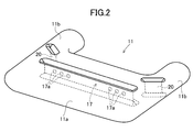
- FIG. 2 is a perspective view when the airbag of the pedestrian airbag device is completely inflated
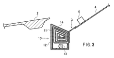
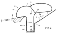
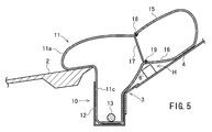
- FIGS. 3 to 5 are longitudinal sectional views in the front-rear direction near the cowl of the automobile equipped with the pedestrian airbag device. is there.
- the automobile 1 includes a hood panel 2, a cowl 3, a windshield 4, an A pillar 5, a wiper 6, a pedestrian airbag device 10, and the like.
- the pedestrian airbag device 10 is installed in the cowl 3, but is not limited thereto, and may be attached to the rear portion of the hood panel 2.
- the pedestrian airbag device 10 includes an airbag 11, a box-shaped retainer 12 that accommodates the folded airbag 11, an inflator 13 for inflating the airbag 11, a lid 14, and the like. .
- the airbag 11 includes a main portion 11a that inflates so as to cover from the rear portion of the hood panel 2 to the front portion of the windshield 4, and extends rearward from the left and right ends of the main portion 11a so that at least the front portion of the A pillar extends. It has a pair of pillar covering portions 11b and 11b that expand so as to cover, and a downward extending portion 11c that continues to the lower surface of the main portion 11a.
- the main portion 11a, the pillar covering portions 11b and 11b, and the downward extending portion 11c communicate with each other.
- the main portion 11a extends continuously from the left end to the right end of the automobile 1.
- the downward extending portion 11 c extends from the lower surface of the main portion 11 a into the retainer 12 in the inflated state of the airbag 11.
- the inflator 13 is disposed in the downward extending portion 11c.
- the inflator 13 has a rod shape and is provided with a gas outlet on one end side.
- the inflator 13 has the longitudinal direction as the left-right direction of the vehicle body.
- a stud bolt (not shown) protruding from the inflator 13 passes through the lower extension portion 11 c and the bottom surface of the retainer 12 and is tightened with a nut, whereby the inflator 13 is fixed to the retainer 12.
- the airbag 11 is configured by sewing a base fabric.
- a base fabric (panel) 15 constituting the upper surface of the main portion 11a and a panel 16 constituting the lower surface of the main portion 11a are connected by a tether panel 17.
- the tether panel 17 extends in the left-right direction of the automobile body, and an upper edge and a lower edge are stitched to the upper panel 15 and the lower panel 16 by sutures 18 and 19, respectively.
- the position of the lower end side of the tether panel 17 (the stitching position between the tether panel 17 and the lower panel 16) is a position facing the wiper 6 in the stopped posture when the airbag 11 is inflated.
- the distance between the left and right end portions of the tether panel 17 and the left and right side portions of the main portion 11a is preferably 300 mm or less, particularly 250 mm or less.
- the width in the vertical direction connecting the panels 15 and 16 of the tether panel 17 is preferably about 80 to 220 mm, particularly about 100 to 200 mm.
- the tether panel 17 does not need to be a single piece, and may be divided into two or more pieces.
- interval which gas passes between the both ends of the left-right direction of the tether panel 17 and the left-right both ends of the main part 11a is open.
- the tether panel 17 is provided with a gas passage opening 17a.
- the opening 17a may be omitted.
- the airbag 11 is folded and accommodated in the retainer 12, and the upper surface of the retainer 12 is closed by the lid 14.
- the folding method of the airbag 11 is arbitrary, such as roll folding, bellows folding, or a combination thereof.
- the airbag folded body is preferably wrapped and held by a shape-retaining cloth (not shown) made of cloth or film.
- the shape retaining cloth is provided with a cleaving portion such as a perforated slit so that the air bag 11 is cleaved when the airbag 11 is inflated.
- the airbag device 10 the upper panel 15 and the lower panel 16 of the airbag 11 are connected by the tether panel 17, and the lower panel 16 near the lower end edge connecting portion of the tether panel 17 is pulled upward. .
- the airbag 11 is formed with a recess H in a portion of the lower surface of the main portion 11 a that faces the wiper 6 in the inflated state from the middle of inflation.
- the upper panel 15 of the main portion 11a is pushed upward by the gas ejected from the inflator 13, thereby being curved upward and convex as shown in FIG. Try to swell. Since the lower panel 16 is connected to the upper panel 15 by the tether panel 17, the lower panel 16 in the vicinity of the lower edge of the tether panel 17 is pulled upward, and the recess H is formed.
- the wiper 6 Since the recess H faces the wiper 6, the wiper 6 is not pushed strongly when the airbag 11 covers the windshield 4, and deformation of the wiper 6 is prevented.
- the wiper 6 is stopped along the cowl 3.
- the wiper 6 is located at the base of the wiper arm (near the wiper pivot).
- the recessed part H faces. For this reason, even when the airbag 11 is inflated during the operation of the wiper, the base portion of the wiper arm is not strongly pressed by the airbag 11 and deformation of the wiper arm is prevented.
- the concave portion H is formed by the tether panel 17, but the airbag 11A of the pedestrian airbag apparatus 10A according to the embodiment shown in FIGS.
- An opening 30 is provided at a position facing the wiper 6 in the state, and a sachet 31 is sewn to the edge of the opening 30 with a suture 32, and the inside of the sachet 31 is defined as a recess H.
- the distance between the end of the opening 30 in the left-right direction of the vehicle body and the left and right side portions of the main portion 11a is preferably 300 mm or less, particularly 250 mm or less, and the width in the front-rear direction is 10 to 100 mm, particularly about 40 to 50 mm is preferable.
- the depth of the recess H is preferably about 30 to 130 mm, particularly about 40 to 100 mm.
- the airbag 11A is not provided with the tether panel 17.
- the other configuration of the airbag apparatus 10A including the airbag 11A is the same as that of the airbag apparatus 10 of FIGS. 1 to 5, and the same reference numerals indicate the same parts.
- the pouch 31 is in a low tension state near the opening 30.
- the airbag 11A having the small bag 31 in such a low tension state is then covered on the front portion of the windshield 4 as shown in FIG. 7, the wiper 6 passes through the opening 30 and the small bag 31 Get inside. For this reason, the airbag 11A does not push the wiper 6 strongly.
- the recess 31 may be formed by connecting the pouch 31 to the upper panel 15 by a tether member and pulling the pouch 31 upward.
- a rectifying cylinder 40 that guides the gas from the inflator 13 in the left-right direction may be disposed in the airbag 11 as in a pedestrian airbag apparatus 10B shown in FIGS.
- the rectifying tube 40 is formed by folding a single base fabric into two and turning it back, and sewing the ends together with a suture thread 41 to form a substantially cylindrical shape.
- the right and left ends of the rectifying cylinder 40 are gas outlets 42 and 43.
- One or a plurality of gas outlets 44 are also provided on the upper surface of the rectifying cylinder 40 in the cylinder axis direction.
- the inflator 13 is disposed inside the rectifying cylinder 40.
- Reference numeral 13 a in FIG. 11 indicates a gas ejection portion of the inflator 13. Since the gas outlet 42 on the left side is close to the gas ejection part 13a, the opening diameter is smaller than that of the gas outlet 43, so that the gas flows out to the left and right evenly.
- this flow straightening cylinder 40 is arranged in the airbag 11, a large amount of the gas ejected from the inflator 13 flows out from the outlets 42 and 43 to the left and right, so that the airbag that is being inflated The speed at which the 11 folding bodies unfold upward from the retainer 12 is reduced. For this reason, when the folded body of the airbag 11 hits the rear edge of the hood panel 2, the force pushing the rear edge becomes small, and the deformation of the rear edge is prevented.
- the rectifying cylinder 40 is sized so that the upper part of the rectifying cylinder 40 does not reach the rear end of the hood panel 2 or the wiper 6 even when the rectifying cylinder 40 is full of gas.
- the rectifying cylinder 40 is installed in the airbag 11 shown in FIGS. 1-5, but the rectifying cylinder 40 may be installed in the airbag 11A shown in FIGS. 6-8.
- the pedestrian airbag device 10 is installed in the cowl 3, but is disposed below the hood panel 2, and when the airbag is inflated, the rear portion of the hood panel 2 is pushed up so that the airbag is It may be an inflatable pedestrian airbag device or the like.
- a single airbag covers the left side A pillar to the right side A pillar, but the pedestrian airbag device having the airbag that covers the left half side of the automobile and the right half side. It may be a pedestrian airbag device having an airbag that covers the vehicle.
Landscapes
- Engineering & Computer Science (AREA)
- Mechanical Engineering (AREA)
- Air Bags (AREA)
Abstract
インフレータが作動してエアバッグが膨張したときにエアバッグからワイパに対して加えられる力が軽減される歩行者用エアバッグ装置を提供する。歩行者用エアバッグ装置10のエアバッグ11は、上側パネル15と下側パネル16とを連結するテザーパネル17を備えている。エアバッグ11の膨張時にテザーパネル17が下側パネル16を引っ張ることにより、ワイパ6を受容する凹部Hが形成される。テザーパネル17の代りに、下側パネル16に開口30及び小袋31を設けてもよい。
Description
本発明は、車体のカウル付近の外面に沿ってエアバッグを膨張させることにより歩行者等(歩行者や二輪車乗員など)を受け止めるようにした歩行者用エアバッグ装置に関する。また、本発明は、この歩行者用エアバッグ装置を備えた自動車に関する。
歩行者用エアバッグ装置は、自動車のカウル付近の外面に沿ってエアバッグを膨張させることにより歩行者等(歩行者や自転車等の二輪車乗員など)を受け止めるように構成されている。
歩行者用エアバッグ装置のエアバッグが膨張すると、ボンネットフードの後縁部、カウル、ウィンドシールド及び左右のAピラーの少なくとも一部がエアバッグによって覆われる。
この歩行者用エアバッグ装置は、折り畳まれたエアバッグを収納するためのリテーナ(ケース)と、エアバッグを膨張させるためのインフレータと、リテーナを閉鎖しているリッド等を備えている。リテーナは車体幅方向に延在した長函状のものである。
特許文献1の図1及び特許文献2の図2には、膨張したエアバッグが自動車のカウル近傍領域の外面を覆うように展開し、この展開したエアバッグがワイパに覆い被さっている状況が示されている。このようにワイパを覆うように膨張したエアバッグは、ワイパをウィンドシールドに押し付け、ワイパ特にワイパアームを変形させるおそれがある。なお、ワイパ非作動時においては、ワイパがエアバッグに近接するので、その可能性が高くなる。
一般に、ワイパは、ワイパピボットと、該ワイパピボットから延出するワイパアームと、該ワイパアームの先端側に取り付けられたワイパブレード等を備えている。ワイパブレードは、ウィンドシールドに接しているが、ワイパアームはウィンドシールドから若干離間している。そのため、膨張しつつあるエアバッグによってワイパアームが押されると、該ワイパアームが変形するおそれがある。
膨張しつつあるエアバッグがワイパブレードに当ったときに、ワイパブレードがねじれて変形することがある。
本発明は、膨張したエアバッグからワイパに対して加えられる力が軽減される歩行者用エアバッグ装置を提供することを目的とする。
本発明の歩行者用エアバッグ装置は、自動車のAピラー、ウィンドシールド及びカウルの少なくとも一部を被覆するように膨張するエアバッグと、該エアバッグが折り畳まれて収容されたリテーナと、該エアバッグを膨張させるためのインフレータとを有する。該エアバッグが膨張完了した状態において、該エアバッグの下面のうちワイパと対面する部分に、該ワイパが入り込む凹部が形成される。
本発明の一態様では、前記エアバッグは、膨張した状態において、該エアバッグの上面を構成する上側パネル及び下面を構成する下側パネルを有しており、該エアバッグ内に、該上側パネルと下側パネルとを連結したテザーパネルが設けられており、該テザーパネルの下縁部は、前記ワイパと対面する部分において下側パネルに連結されており、エアバッグ膨張状態において、該テザーパネルによって下側パネルが上方に引っ張られることにより、前記凹部が形成される。
本発明の別の一態様では、前記エアバッグは、膨張した状態において、該エアバッグの上面を構成する上側パネル及び下面を構成する下側パネルを有しており、該下側パネルには、該エアバッグが膨張完了した状態においてワイパに対面する位置に開口が設けられており、該エアバッグ内に配置された小袋が該開口の縁部に連結されており、該小袋により前記凹部が形成される。
本発明の歩行者用エアバッグ装置では、膨張したエアバッグ下面のうちワイパに対面する部分に凹部が形成され、ワイパが該凹部に受容されるので、エアバッグがワイパを押す力が軽減される。
以下、図面を参照して実施の形態について説明する。以下の説明において、前後及び左右は、歩行者用エアバッグ装置を搭載した自動車の前後及び左右を表わす。
図1は第1の実施の形態に係る歩行者用エアバッグ装置10を搭載した自動車の前部の平面図であり、エアバッグが展開した状態を示している。図2はこの歩行者用エアバッグ装置のエアバッグの膨張完了時の斜視図であり、図3~5はこの歩行者用エアバッグ装置を備えた自動車のカウル付近の前後方向の縦断面図である。
自動車1はフードパネル2、カウル3、ウィンドシールド4、Aピラー5、ワイパ6、歩行者用エアバッグ装置10等を備えている。この実施の形態では、歩行者用エアバッグ装置10は、カウル3に設置されているが、これに限定されるものではなく、フードパネル2の後部に取り付けられてもよい。
この歩行者用エアバッグ装置10は、エアバッグ11と、折り畳まれたエアバッグ11を収容する函状のリテーナ12と、エアバッグ11を膨張させるためのインフレータ13と、リッド14等を備えている。
エアバッグ11は、フードパネル2の後部からウィンドシールド4の前部までを覆うように膨張する主部11aと、該主部11aの左右両端側から後方に延出してAピラーの少なくとも前部を被覆するように膨張する1対のピラー被覆部11b,11bと、該主部11aの下面に連なる下方延出部11cとを有している。主部11a、ピラー被覆部11b,11b及び下方延出部11cは連通している。
エアバッグ11が膨張した状態において、主部11aは、自動車1の左端から右端まで連続して延在している。
下方延出部11cは、エアバッグ11の膨張状態において、主部11aの下面からリテーナ12内にまで延在している。この実施の形態では、下方延出部11c内にインフレータ13が配置されている。
インフレータ13はロッド状であり、一端側にガス噴出口が設けられている。インフレータ13は、長手方向を車体左右方向としている。インフレータ13から突設されたスタッドボルト(図示略)が下方延出部11c及びリテーナ12の底面を貫通し、ナット締めされることにより、インフレータ13がリテーナ12に固定されている。
エアバッグ11は基布を縫製することにより構成されている。この実施の形態では、主部11aの上面を構成する基布(パネル)15と、主部11aの下面を構成するパネル16とがテザーパネル17によって連結されている。
テザーパネル17は、自動車車体の左右方向に延在しており、上縁及び下縁がそれぞれ縫合糸18,19によって上側パネル15及び下側パネル16に縫合されている。
テザーパネル17の下端辺の位置(テザーパネル17と下側パネル16との縫合位置)は、エアバッグ11が膨張完了した状態において、停止姿勢のワイパ6に対面する位置である。
テザーパネル17の左右方向の端部と主部11aの左右の側辺部との距離は300mm以下特に250mm以下であることが好ましい。テザーパネル17のパネル15,16を結ぶ上下方向の幅員は80~220mm特に100~200mm程度が好ましい。テザーパネル17は1枚物である必要はなく、2枚以上に分割されてもよい。
テザーパネル17の左右方向の両端と主部11aの左右両側端との間には、ガスが通過する間隔があいている。この実施の形態では、テザーパネル17に、ガス通過用の開口17aが設けられているが、この開口17aは省略されてもよい。
この実施の形態では、主部11aとピラー被覆部11bとが連なる部分付近にサイドテザーパネル20が設けられている。サイドテザーパネル20も、上縁及び下縁が上下のパネル15,16に縫合糸によって縫着されている。サイドテザーパネル20は、自動車の左右幅方向の中央側ほど自動車前方となるように設けられている。サイドテザーパネル20にもガス通過用開口が設けられてもよい。
このエアバッグ11が折り畳まれてリテーナ12に収容され、リッド14によって該リテーナ12の上面が閉鎖される。エアバッグ11の折り畳み方法は、ロール折り、蛇腹折り、それらの併用など任意である。
エアバッグ11を折り畳んだ後、エアバッグ折畳体を布やフィルム等よりなる保形クロス(図示略)によって被包して保形するのが好ましい。この保形クロスには、エアバッグ11が膨張するときに開裂するようにミシン目状のスリット等の開裂部が設けられている。
この歩行者用エアバッグ装置10を搭載した自動車1が歩行者等と接触してインフレータ13が作動すると、エアバッグ11が図4の状態を経て図1,5のように膨張展開し、カウル3、フードパネル2の後部及びウィンドシールド4の前部が主部11aで覆われ、Aピラー5の少なくとも前部及びその近傍がピラー被覆部11bで覆われ、歩行者等が直接にカウル3やAピラー5に当ることが防止される。
このエアバッグ装置10にあっては、エアバッグ11の上側パネル15と下側パネル16とがテザーパネル17によって連結されており、テザーパネル17の下端縁連結部付近の下側パネル16が上方に引っ張られる。これにより、エアバッグ11は、図4,5のように、膨張途中から膨張完了状態において、主部11aの下面のうちワイパ6に対面する部分に凹部Hが形成される。
即ち、エアバッグ11の主部11aが膨張する場合、主部11aの上側パネル15は、インフレータ13から噴出したガスによって上方に押されることにより、図4のように、上方に向って凸に湾曲するように膨張しようとする。この上側パネル15に対し下側パネル16がテザーパネル17によって連結されているので、テザーパネル17下縁付近の下側パネル16が上方に引き上げられ、凹部Hが形成される。
この凹部Hがワイパ6に対面するため、エアバッグ11がウィンドシールド4に被さるときにワイパ6を強く押すことがなく、ワイパ6の変形が防止される。
図1では、ワイパ6はカウル3に沿った停止姿勢となっているが、ワイパ6が作動しているときにエアバッグ11が膨張した場合でも、ワイパ6のワイパアームの基部(ワイパピボット近傍)に凹部Hが対面する。そのため、ワイパ作動中にエアバッグ11が膨張した場合でも、ワイパアームの基部がエアバッグ11によって強く押されることがなく、ワイパアームの変形が防止される。
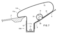
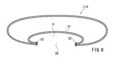
上記実施の形態では、テザーパネル17によって凹部Hを形成しているが、図6~8に示す実施の形態に係る歩行者用エアバッグ装置10Aのエアバッグ11Aでは、下側パネル16のうち、停止状態のワイパ6に対面する位置に開口30を設け、この開口30の縁部に小袋31を縫合糸32によって縫着し、この小袋31内を凹部Hとしている。
下側パネル16を平たく広げた状態において、開口30の車体左右方向の端部と主部11aの左右の側辺部との距離は300mm以下特に250mm以下であることが好ましく、前後方向の幅は10~100mm特に40~50mm程度が好ましい。凹部Hの深さは30~130mm特に40~100mm程度が好ましい。
このエアバッグ11Aは、テザーパネル17が設けられていない。このエアバッグ11Aを備えたエアバッグ装置10Aのその他の構成は図1~5のエアバッグ装置10と同一であり、同一符号は同一部分を示している。
図6のように、このエアバッグ11Aが膨張した場合、小袋31は開口30付近で低張力状態となっている。このように低張力状態となっている小袋31を有したエアバッグ11Aが、その後、図7のようにウィンドシールド4の前部に覆い被さった場合、ワイパ6は、開口30を通って小袋31内に入り込む。このため、エアバッグ11Aがワイパ6を強く押すことがない。
小袋31をテザー部材によって上側パネル15に連結し、小袋31を上方に引き上げて凹部Hを形成してもよい。
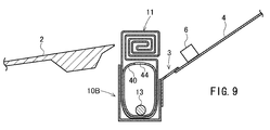
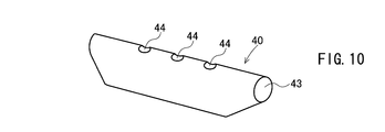
本発明では、図9~11に示す歩行者用エアバッグ装置10Bのように、インフレータ13からのガスを左右方向に導く整流筒40をエアバッグ11内に配置してもよい。この実施の形態では、整流筒40は、1枚の基布を二ツ折りして折り返し、端辺同士を縫合糸41で縫着して略筒状としたものである。この整流筒40の左右両端はガス流出口42,43となっている。整流筒40の筒軸方向の途中の上面にも、1個又は複数個のガス流出口44が設けられている。この整流筒40の内部にインフレータ13が配置される。図11の符号13aは、インフレータ13のガス噴出部を示す。左側のガス流出口42は、このガス噴出部13aに近いので、ガス流出口43よりも開口径が小さくなっており、左右にガスが均等に流出するよう構成されている。
この整流筒40をエアバッグ11内に配置しておくと、インフレータ13から噴出したガスのうち多くのものが流出口42,43から左方及び右方に流出するので、膨張しつつあるエアバッグ11の折り畳み体がリテーナ12から上方に展開するときの速度が小さくなる。このため、エアバッグ11の折り畳み体がフードパネル2の後縁に当ったときに該後縁を押す力が小さくなり、該後縁の変形が防止される。
整流筒40は、ガスによって膨満した状態においても、該整流筒40の上部がフードパネル2の後端やワイパ6に達しない大きさとされる。
図9~11では、図1~5に示すエアバッグ11内に整流筒40が設置されているが、図6~8に示すエアバッグ11Aに整流筒40が設置されてもよい。
上記実施の形態は、いずれも本発明の一例であり、本発明は図示の状態に限定されない。本発明では、膨張したエアバッグの下面のうちワイパ対面部分に凹部を形成することができる他の手段を採用してもよい。
上記実施の形態では、歩行者用エアバッグ装置10はカウル3に設置されているが、フードパネル2の下側に配置され、エアバッグの膨張時にフードパネル2の後部が押し上げられてエアバッグが膨張するタイプの歩行者用エアバッグ装置などであってもよい。
上記実施の形態では、1個のエアバッグによって左側Aピラーから右側Aピラーまでを覆うようにしているが、自動車の左半側を覆うエアバッグを有した歩行者用エアバッグ装置と右半側を覆うエアバッグを有した歩行者用エアバッグ装置であってもよい。
本発明を特定の態様を用いて詳細に説明したが、本発明の意図と範囲を離れることなく様々な変更が可能であることは当業者に明らかである。
本出願は、2014年12月22日付で出願された日本特許出願2014-258867に基づいており、その全体が引用により援用される。
本出願は、2014年12月22日付で出願された日本特許出願2014-258867に基づいており、その全体が引用により援用される。
1 自動車
2 フードパネル
3 カウル
4 ウィンドシールド
5 Aピラー
6 ワイパ
10,10A,10B 歩行者用エアバッグ装置
11,11A エアバッグ
11a 主部
11b ピラー被覆部
11c 下方延出部
12 リテーナ
13 インフレータ
15 上側パネル
16 下側パネル
17 テザーパネル
20 サイドテザーパネル
30 開口
31 小袋
40 整流筒
2 フードパネル
3 カウル
4 ウィンドシールド
5 Aピラー
6 ワイパ
10,10A,10B 歩行者用エアバッグ装置
11,11A エアバッグ
11a 主部
11b ピラー被覆部
11c 下方延出部
12 リテーナ
13 インフレータ
15 上側パネル
16 下側パネル
17 テザーパネル
20 サイドテザーパネル
30 開口
31 小袋
40 整流筒
Claims (5)
- 自動車のAピラー、ウィンドシールド及びカウルの少なくとも一部を被覆するように膨張するエアバッグと、
該エアバッグが折り畳まれて収容されたリテーナと、
該エアバッグを膨張させるためのインフレータと、
を有する歩行者用エアバッグ装置において、
該エアバッグが膨張完了した状態において、該エアバッグの下面のうちワイパと対面する部分に、該ワイパが入り込む凹部が形成されることを特徴とする歩行者用エアバッグ装置。 - 請求項1において、前記エアバッグは、膨張した状態において、該エアバッグの上面を構成する上側パネル及び下面を構成する下側パネルを有しており、
該エアバッグ内に、該上側パネルと下側パネルとを連結したテザーパネルが設けられており、
該テザーパネルの下縁部は、前記ワイパと対面する部分において下側パネルに連結されており、
エアバッグ膨張状態において、該テザーパネルによって下側パネルが上方に引っ張られることにより、前記凹部が形成されることを特徴とする歩行者用エアバッグ装置。 - 請求項2において、前記エアバッグが膨張完了した状態において、前記テザーパネルの上下方向の幅員が80~220mmであることを特徴とする歩行者用エアバッグ装置。
- 請求項1において、前記エアバッグは、膨張した状態において、該エアバッグの上面を構成する上側パネル及び下面を構成する下側パネルを有しており、
該下側パネルには、該エアバッグが膨張完了した状態においてワイパに対面する位置に開口が設けられており、
該エアバッグ内に配置された小袋が該開口の縁部に連結されており、該小袋により前記凹部が形成されることを特徴とする歩行者用エアバッグ装置。 - 請求項1ないし4のいずれか1項に記載の歩行者用エアバッグ装置を備えた自動車。
Priority Applications (1)
| Application Number | Priority Date | Filing Date | Title |
|---|---|---|---|
| CN201580067937.3A CN107000673B (zh) | 2014-12-22 | 2015-09-08 | 行人用气囊装置及汽车 |
Applications Claiming Priority (2)
| Application Number | Priority Date | Filing Date | Title |
|---|---|---|---|
| JP2014258867A JP6451303B2 (ja) | 2014-12-22 | 2014-12-22 | 歩行者用エアバッグ装置 |
| JP2014-258867 | 2014-12-22 |
Publications (1)
| Publication Number | Publication Date |
|---|---|
| WO2016103795A1 true WO2016103795A1 (ja) | 2016-06-30 |
Family
ID=56149837
Family Applications (1)
| Application Number | Title | Priority Date | Filing Date |
|---|---|---|---|
| PCT/JP2015/075398 Ceased WO2016103795A1 (ja) | 2014-12-22 | 2015-09-08 | 歩行者用エアバッグ装置及び自動車 |
Country Status (3)
| Country | Link |
|---|---|
| JP (1) | JP6451303B2 (ja) |
| CN (1) | CN107000673B (ja) |
| WO (1) | WO2016103795A1 (ja) |
Families Citing this family (3)
| Publication number | Priority date | Publication date | Assignee | Title |
|---|---|---|---|---|
| JP6822921B2 (ja) * | 2017-08-14 | 2021-01-27 | トヨタ自動車株式会社 | 歩行者保護エアバッグ |
| EP3590774B1 (en) * | 2018-07-05 | 2021-05-26 | Autoliv Development AB | A pedestrian protection airbag device |
| JP7022347B2 (ja) * | 2018-12-25 | 2022-02-18 | 豊田合成株式会社 | 歩行者用エアバッグ |
Citations (3)
| Publication number | Priority date | Publication date | Assignee | Title |
|---|---|---|---|---|
| JP2007203815A (ja) * | 2006-01-31 | 2007-08-16 | Nippon Plast Co Ltd | 車外用エアバッグ装置 |
| JP2008213523A (ja) * | 2007-02-28 | 2008-09-18 | Toyoda Gosei Co Ltd | 歩行者用エアバッグ装置 |
| JP2010126078A (ja) * | 2008-11-28 | 2010-06-10 | Nippon Plast Co Ltd | エアバッグ及びエアバッグ装置 |
Family Cites Families (4)
| Publication number | Priority date | Publication date | Assignee | Title |
|---|---|---|---|---|
| JP2005138749A (ja) * | 2003-11-07 | 2005-06-02 | Takata Corp | 歩行者等の保護装置 |
| JP2006248332A (ja) * | 2005-03-09 | 2006-09-21 | Takata Corp | 歩行者等保護用エアバッグ及び歩行者等保護用エアバッグ装置 |
| CN101374699A (zh) * | 2006-01-17 | 2009-02-25 | 高田株式会社 | 行人用气囊装置 |
| JP4899861B2 (ja) * | 2006-12-28 | 2012-03-21 | 豊田合成株式会社 | 歩行者用エアバッグ装置 |
-
2014
- 2014-12-22 JP JP2014258867A patent/JP6451303B2/ja active Active
-
2015
- 2015-09-08 WO PCT/JP2015/075398 patent/WO2016103795A1/ja not_active Ceased
- 2015-09-08 CN CN201580067937.3A patent/CN107000673B/zh active Active
Patent Citations (3)
| Publication number | Priority date | Publication date | Assignee | Title |
|---|---|---|---|---|
| JP2007203815A (ja) * | 2006-01-31 | 2007-08-16 | Nippon Plast Co Ltd | 車外用エアバッグ装置 |
| JP2008213523A (ja) * | 2007-02-28 | 2008-09-18 | Toyoda Gosei Co Ltd | 歩行者用エアバッグ装置 |
| JP2010126078A (ja) * | 2008-11-28 | 2010-06-10 | Nippon Plast Co Ltd | エアバッグ及びエアバッグ装置 |
Also Published As
| Publication number | Publication date |
|---|---|
| JP2016117419A (ja) | 2016-06-30 |
| CN107000673B (zh) | 2019-10-22 |
| JP6451303B2 (ja) | 2019-01-16 |
| CN107000673A (zh) | 2017-08-01 |
Similar Documents
| Publication | Publication Date | Title |
|---|---|---|
| JP4893043B2 (ja) | 歩行者用エアバッグ装置 | |
| JP2005239054A (ja) | ニーバッグ及び乗員脚部保護装置 | |
| JP4403913B2 (ja) | 歩行者用エアバッグ装置 | |
| JP2008273250A (ja) | 歩行者用エアバッグ装置 | |
| JP2007190988A (ja) | 座席シート装置 | |
| JP6519275B2 (ja) | エアバッグ及び歩行者用エアバッグ装置 | |
| JP2008230291A (ja) | エアバッグ及びエアバッグ装置 | |
| JP6451303B2 (ja) | 歩行者用エアバッグ装置 | |
| JP6600993B2 (ja) | 歩行者用エアバッグ装置 | |
| JP6677064B2 (ja) | 歩行者用エアバッグ装置及び自動車 | |
| JP2009035055A (ja) | エアバッグ及びエアバッグ装置 | |
| WO2007088694A1 (ja) | エアバッグ及びエアバッグ装置 | |
| JP4297014B2 (ja) | エアバッグ装置 | |
| JP6277946B2 (ja) | 歩行者用エアバッグ装置 | |
| JP2007152967A (ja) | 歩行者用エアバッグ及び装置 | |
| JP6443039B2 (ja) | 歩行者用エアバッグ装置 | |
| JP2007030614A (ja) | エアバッグ装置 | |
| JP2015134564A (ja) | 歩行者用エアバッグ装置及び自動車 | |
| JP4407548B2 (ja) | 歩行者用エアバッグ装置 | |
| JP2004338639A (ja) | 後突用エアバッグの折り畳み方法及び後突用エアバッグ装置 | |
| JP6609459B2 (ja) | 脚部用エアバッグ装置 | |
| JP2006096289A (ja) | 歩行者用エアバッグ装置 | |
| JP6291855B2 (ja) | 歩行者用エアバッグ装置及び自動車 | |
| JP6070511B2 (ja) | 歩行者用エアバッグ装置 | |
| JP2007030616A (ja) | エアバッグ装置 |
Legal Events
| Date | Code | Title | Description |
|---|---|---|---|
| 121 | Ep: the epo has been informed by wipo that ep was designated in this application |
Ref document number: 15872364 Country of ref document: EP Kind code of ref document: A1 |
|
| NENP | Non-entry into the national phase |
Ref country code: DE |
|
| 122 | Ep: pct application non-entry in european phase |
Ref document number: 15872364 Country of ref document: EP Kind code of ref document: A1 |