WO2016103384A1 - 部品組付方法 - Google Patents
部品組付方法 Download PDFInfo
- Publication number
- WO2016103384A1 WO2016103384A1 PCT/JP2014/084264 JP2014084264W WO2016103384A1 WO 2016103384 A1 WO2016103384 A1 WO 2016103384A1 JP 2014084264 W JP2014084264 W JP 2014084264W WO 2016103384 A1 WO2016103384 A1 WO 2016103384A1
- Authority
- WO
- WIPO (PCT)
- Prior art keywords
- lubricating oil
- hand
- support means
- assembly
- component
- Prior art date
- Legal status (The legal status is an assumption and is not a legal conclusion. Google has not performed a legal analysis and makes no representation as to the accuracy of the status listed.)
- Ceased
Links
Images
Classifications
-
- B—PERFORMING OPERATIONS; TRANSPORTING
- B23—MACHINE TOOLS; METAL-WORKING NOT OTHERWISE PROVIDED FOR
- B23P—METAL-WORKING NOT OTHERWISE PROVIDED FOR; COMBINED OPERATIONS; UNIVERSAL MACHINE TOOLS
- B23P19/00—Machines for simply fitting together or separating metal parts or objects, or metal and non-metal parts, whether or not involving some deformation; Tools or devices therefor so far as not provided for in other classes
- B23P19/04—Machines for simply fitting together or separating metal parts or objects, or metal and non-metal parts, whether or not involving some deformation; Tools or devices therefor so far as not provided for in other classes for assembling or disassembling parts
-
- B—PERFORMING OPERATIONS; TRANSPORTING
- B23—MACHINE TOOLS; METAL-WORKING NOT OTHERWISE PROVIDED FOR
- B23P—METAL-WORKING NOT OTHERWISE PROVIDED FOR; COMBINED OPERATIONS; UNIVERSAL MACHINE TOOLS
- B23P21/00—Machines for assembling a multiplicity of different parts to compose units, with or without preceding or subsequent working of such parts, e.g. with program control
Definitions
- the present invention relates to a part assembling method for assembling an assembly target part to a counterpart part, and in particular, when the assembly target part supported by the support means is assembled to the counterpart part, the assembly target part is lubricated.
- the present invention relates to a method for assembling parts when oiling by dripping oil is required.
- Patent Document 1 discloses a technique that automates the work of assembling a crankshaft to a cylinder block that is a base of an engine in an automobile engine assembly process, for example.
- it is necessary to support the bearing of the journal portion on the crankshaft side when assembling the crankshaft supported by the transport unit to the cylinder block waiting in a state where the crankshaft is inverted upside down.
- Even the bearing metal is assembled to the cylinder block which is the other side substantially integrally with the crankshaft.
- crankshaft may be rotated and slid at the bearing support portion in the crankshaft assembly process or the post-process after the engine assembly is further advanced. It is necessary to lubricate and drop a suitable amount of lubricating oil on the sliding part.
- a spring-biased check valve is provided in the nozzle in order to fly a small amount of lubricating oil into a so-called ball shape. It takes a long time for the lubricating oil to jump out, and it is difficult to cope with oiling work that requires speeding up.
- Patent Document 3 it is a method in which the other side member such as a transport chain continuously running on a portion swollen by the surface tension among the oil sent from the nozzle is contacted and lubricated, It takes time to adjust the gap between the nozzle and the counterpart member, and it is difficult to cope with the lubrication work that requires speeding up as in the technique described in Patent Document 2, and is described in Patent Documents 2 and 3. All of these technologies are difficult to adopt in the engine automatic assembly process.
- the present invention has been made paying attention to the problems of the prior art as described above.
- the assembly target part supported by the support means is used for the support means. It is intended to provide a method that enables accurate lubrication of an appropriate amount of lubricating oil in a very short time when assembling to the counterpart part that is waiting below the part to be assembled with a downward movement. is there.
- the support means among the support means The lubrication nozzle is provided at a position above the assembly target part supported by the above-mentioned method, and the descending speed is rapidly decelerated at the end of the descending operation of the support means, so that the lubricating oil held by the lubrication nozzle is It is designed to drop onto the assembly target part by the inertial force accompanying the deceleration.
- the lubrication time of the lubricating oil is set as the cycle time of the part assembly operation. There is no need to consider. Therefore, when the assembly work of the parts based on the lowering operation of the support means including the lubrication operation is set to one cycle, the cycle time can be greatly shortened, and the production by making the cycle time redundant even in an automated assembly facility. It does not cause a decline in sex.
- the time chart which shows the correlation with the descent speed of a hand, lubricating oil application timing, and the mechanical relative positional relationship of the crankshaft S of the hand side with respect to a cylinder block.
- Explanatory drawing which shows the behavior at the time of dripping of lubricating oil when not using the inertial force by the rapid deceleration at the time of a hand fall like this Embodiment as a comparative example.
- Explanatory drawing which shows the behavior at the time of dripping of the lubricating oil in this Embodiment.
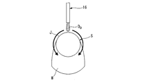
- Expansive explanatory drawing which shows the behavior at the time of the lower surface spreading of lubricating oil.
- FIGS. 1 to 8 show a more specific form for carrying out the parts assembling method according to the present invention.
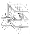
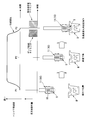
- FIG. 1 shows a process of assembling the crankshaft S to the cylinder block B as a part of the assembling process of the automobile engine. The outline of the assembly equipment is shown. Therefore, the crankshaft S is a part to be assembled, and the cylinder block B is a counterpart part.
- FIG. 1 illustrates an inline 4-cylinder type cylinder block B and a crankshaft S.
- a pair of Y-axis slide guide mechanisms 3 parallel to each other are provided on a machine frame 2 erected on a floor F together with a slide drive mechanism (not shown).
- An X-axis slide guide mechanism 5 is provided on the slider 4 of the Y-axis slide guide mechanism 3 together with a slide drive mechanism (not shown) so as to straddle both.
- a Z-axis slide guide mechanism 7 is provided on the slider 6 of the X-axis slide guide mechanism 5 together with a slide drive mechanism (not shown).
- a bracket 9 is fixed to the slider 8 of the Z-axis slide guide mechanism 7. Yes.
- the three-axis robot 1 is an orthogonal three-axis type robot 1 having a degree of freedom in each of the X-, Y-, and Z-directions by these three Y-axis slide guide mechanisms 3, X-axis slide guide mechanisms 5, and Z-axis slide guide mechanisms 7.
- a built-in bracket 9 attached to the slider 8 of the Z-axis slide guide mechanism 7 is equipped with a robot hand (hereinafter simply referred to as a hand) 10 as a support means. As will be described later, the hand 10 grips the crankshaft S as the part to be assembled.
- a pallet-type transport device 11 is provided inside the machine casing 2.
- a pallet 11a on which a cylinder block B as a counterpart component to which the crankshaft S is assembled is positioned and placed, a pallet 11b on which a bearing cap C or the like as an accessory component is placed, Are carried in from the previous process in a form arranged in series and positioned at a predetermined position.
- the cylinder block B on the pallet 11a is positioned in a so-called upside down posture so that the crank chamber that receives the crankshaft S faces upward.
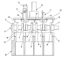
- FIG. 2 is an enlarged view showing the relationship between the hand 10 including the crankshaft S shown in FIG. 1 and the cylinder head B
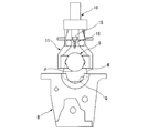
- FIG. 3 is an explanatory diagram on the right side of FIG.
- the hand 10 is a twin gripper type in which two sets of grippers 11 of a so-called two-finger grip type are juxtaposed in the longitudinal direction.
- the crankshaft S is gripped by using two main journal portions J as gripping portions of the main journal portions J, J... As the shaft-shaped portions provided side by side. More specifically, if the hand 10 grips the crankshaft S in a standby position (not shown) by the autonomous operation of the robot 1 itself, the hand 10 transports the crankshaft S to a position directly above the cylinder block B and waits below.
- the cylinder block B is assembled.
- reference numeral 12 in FIGS. 2 and 3 denotes a direct acting actuator for opening and closing each gripper 11.
- Reference numeral W denotes a counterweight portion of the crankshaft S
- reference symbol Q denotes a bearing portion (bearing metal) on the cylinder block B side.
- the hand 10 shown in FIGS. 1 to 3 has a function of dripping lubricating oil onto the main journal portion J on the crankshaft S side that is a sliding portion with the cylinder block B when the crankshaft S is assembled to the cylinder block B. As shown in FIG. 1, the hand 10 is connected to a lubricating oil supply device 13 by a pipe 14.
- a long holder plate 15 is laid across the hand 10 so as to straddle two grippers 11, and the holder plate 15 has a lubricant oil dripping along the longitudinal direction.
- the plurality of oiling nozzles 16 are arranged downward.
- lubricating oil is applied to the main journal portion J as a shaft-like portion that sits on the bearing portion (bearing metal) Q on the cylinder block B side of the crankshaft S and slides with the bearing portion Q.
- oil supply nozzles 16 are provided at positions corresponding to the plurality of main journal portions J on the crankshaft S side of the holder plate 15. That is, a plurality of oiling nozzles 16 are provided in series along the longitudinal direction of the holder plate 15, and correspond to the top portion of the uppermost portion of the cylindrical outer peripheral surface in the cross section perpendicular to the axis of each main journal portion J. The position of each lubrication nozzle 16 is set so that the position of the tip opening of the lubrication nozzle 16 is oriented.
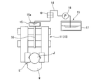
- FIG. 4 shows a lubricating oil supply system by the lubricating oil supply device 13 shown in FIG.
- the lubricating oil supply device 13 includes a lubricating oil tank 17 in which a predetermined lubricating oil is stored and a pump 18, and the lubricating oil in the lubricating oil tank 17 is directed toward the respective oiling nozzles 16 when the pump 18 is activated. It is pumped through the pipe 14 and the quick joint 19.
- the holder plate 15 is formed in a hollow shape having a common oil passage 15a in the longitudinal direction, and each of the oil supply nozzles 16 is connected to the holder plate 15 in a downward direction so as to branch from the common oil passage 15a. Yes.
- the relative positioning of the crankshaft S held by the hand 10 of the robot 1 and the cylinder block B waiting below the robot 1 is performed as shown in FIG. This is done in advance by autonomous operation. Therefore, the crankshaft S gripped by the hand 10 is lowered together with the hand 10 (so-called approach operation), and the main journal portion J on the crankshaft S side is a predetermined amount rather than sitting on each bearing portion Q of the cylinder block B. The lowering operation of the hand 10 is stopped at the front position.
- a predetermined amount of lubricating oil is dripped from the respective oil supply nozzles 16 toward the upper surface side of each main journal portion J almost at the same time or slightly after the hand 10 stops.
- the dropped lubricating oil is instantly spread on the upper surface due to its own weight and spreads in the longitudinal direction and the circumferential direction of the main journal portion J, and also travels down the outer peripheral surface on the side surface side of the main journal portion J.
- the lower surface is spread over a wide range up to the lower surface side of the outer peripheral surface of the main journal portion J.
- a part of the lubricating oil is also transferred to the bearing portion Q on the cylinder block B side where the main journal portion J is seated.
- FIG. 5 shows the correlation between the descending speed of the hand 10 and the lubricant application timing, and the mechanical relative positional relationship of the crankshaft S on the hand 10 side with respect to the cylinder block B.
- the hand 10 accelerates rapidly from the descending start position P1 and reaches a predetermined speed.
- the hand 10 is at a constant speed at an intermediate position P2 between the descending start position P1 and the descending stop position P2.
- the vehicle is suddenly decelerated at a position a predetermined amount before the descent stop position P3, and finally each main journal portion J on the crankshaft S side is seated on each bearing portion Q of the cylinder block B on the other side. It shall be stopped in a stationary state at the descent stop position P3 before a predetermined amount.
- the acceleration / deceleration when the hand 10 is suddenly accelerated and decelerated is about 1 G, for example.
- the pump 18 of the lubricating oil supply device 13 shown in FIGS. 1 and 4 is activated for a predetermined time almost simultaneously with the sudden deceleration of the hand 10, and the pipe 14 and the holder plate 15 shown in FIG.
- the lubricating oil filled in is brought into a predetermined pressure state.
- the pressurizing force of the pump 18 is adjusted so that the lubricating oil is not pushed out from the front end opening portion of each submerged nozzle 16 even with such a predetermined pressure state.
- the lubricating oil is dropped from the oil injection nozzle 16 at a position corresponding to the top of the top surface of the cylindrical outer peripheral surface of each main journal portion J that is perpendicular to the axis. Therefore, the dropped lubricating oil spreads to the upper surface side of the main journal portion J as its upper surface expands due to its own weight, but also travels down the outer peripheral surface on the side surface side of the main journal portion J, thereby expanding the lower surface of the main journal. Part of the lubricating oil is also transferred to the bearing part Q on the cylinder block B side where the main journal part J is to be seated while being spread over a wide range toward the lower surface side of the outer peripheral surface of the part J. Will fall.
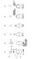
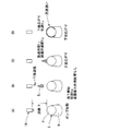
- FIG. 6 shows, as a comparative example, behavior when dripping the lubricating oil when the inertia force due to rapid deceleration when the hand is lowered as in the above embodiment is not used
- FIG. 7 shows the lubrication in the above embodiment. The behavior when oil is dripped is shown. 6 and 7 are examples in which the lubricating oil is dropped by starting the pump 18 from the oil injection nozzle 16 positioned above the main journal portion J by the distance h.
- the initial velocity V 02 at the start of the dropping of the oil droplets D O in FIG. 7, the time required during the dropping of (C) in FIG. 6 and the oil droplets D O as in FIG. The time required to spread the upper surface can be substantially ignored.
- the arrival times t 1 and t 2 are both expressed by the following equation (1) in which t 1 and t 2 are replaced with t.
- t ⁇ (2h / g) + td (1)
- td is a delay time from when the pump 18 is started to when discharge is actually started.
- the crankshaft S gripped by the hand 10 is assembled to the cylinder block B waiting underneath, the inertial force accompanying the rapid deceleration at the end of the lowering operation of the hand 10 is used. Since the lubricating oil is dripped, the lubricating oil dripping time itself can be greatly shortened as described above, as well as the operations required for dripping the lubricating oil in a series of assembly operations. There is no need to consider time, and the cycle time when performing automatic assembly can be shortened. Therefore, productivity is not reduced.
- the lubricating oil is dripped using the inertial force accompanying the rapid deceleration at the end of the lowering operation of the hand 10, so that the plurality of oiling nozzles 16 can be dripped almost simultaneously and reliably, There is no occurrence of defective dropping at a specific oiling nozzle 16.
- the lubricating oil in the lubricating oil tank 17 in the lubricating oil supply device 13 shown in FIGS. 1 and 4 is pumped by the pump 18, but the pump 18 is not necessarily required.
- the pump 18 instead of the pump 18, there may be provided means capable of always pressurizing a space other than the lubricating oil occupation space with a predetermined pressure in the sealed lubricating oil tank 17.
- the pump 18 and the pressurizing means can be eliminated.
- the lubricating oil nozzles 16 are arranged at positions corresponding to the main journal portions J of the crankshaft S gripped by the hand 10, and the lubricating oil is directed from the lubricating oil nozzles 16 toward the main journal portions J.
- the present invention is not limited to this embodiment.
- Lubricating oil can also be dripped toward each pin journal part at the same time that an oiling nozzle is arranged at a position corresponding to each part and dripping the lubricating oil toward each main journal part J.
- the crankshaft S is assembled to the cylinder block B of the automobile engine
- the scope of application of the present invention is not limited to this.
- the present invention can be applied to a loose case where the assembly target part needs to be lubricated by dripping lubricant when the assembly target part is assembled to the counterpart part.
Landscapes
- Engineering & Computer Science (AREA)
- Mechanical Engineering (AREA)
- Shafts, Cranks, Connecting Bars, And Related Bearings (AREA)
Abstract
ハンド(10)で把持しているクランクシャフト(S)をハンド(10)の下降動作によりシリンダブロック(B)の軸受部(Q)に組み付ける際に、ハンド(10)のうち把持しているクランクシャフト(S)の各メインジャーナル部(J)よりも上方位置に注油ノズル(16)を設けておく。ハンド(10)の下降動作の末期にその下降速度を急減速させて、注油ノズル(16)が保有している潤滑油をハンド(10)の急減速に伴う慣性力によってクランクシャフト(S)の各メインジャーナル部(J)に滴下する。これにより、シリンダブロック(B)に対するクランクシャフト(S)の組付動作サイクル内において、瞬時に且つ正確にクランクシャフトの各メインジャーナル部(J)に注油することができる。
Description
本発明は、相手側部品に対して組付対象部品を組み付ける部品組付方法に関し、特に支持手段に支持されている組付対象部品を相手側部品に組み付ける際に、当該組付対象部品に潤滑油の滴下による注油が必要な場合の部品組付方法に関する。
自動車用エンジンの組立工程において、例えばエンジンの母体となるシリンダブロックに対してクランクシャフトを組み付ける作業を自動化した技術が特許文献1に開示されている。この特許文献1に記載された技術では、搬送ユニットで支持したクランクシャフトを、その下方で天地反転させた状態で待機しているシリンダブロックに組み付けるにあたり、クランクシャフト側のジャーナル部の軸受支持に必要な軸受メタルまでも実質的にクランクシャフトと一体的に相手側となるシリンダブロックに対して組み付けるようにしたものである。
そして、上記クランクシャフトの組付工程あるいはエンジン組立が一段と進捗した後工程において、クランクシャフトを回転させて軸受支持部にて摺動させることがあるため、摺動部に傷が発生しないように予め注油して摺動部に適量の潤滑油を滴下しておく必要がある。
そこで、シリンダブロックに対してクランクシャフトを組み付ける直前に、シリンダブロックの軸受部またはクランクシャフトのジャーナル部に注油ノズルにて注油する試みがなされている。
なお、上記エンジンの自動組立工程に採用されているものではないが、注油量の均一化を図る注油(給油)方法として特許文献2,3に記載されたものが提案されている。
しかしながら、上記エンジンの自動組立工程での注油方法では、シリンダブロックの軸受部またはクランクシャフトのジャーナル部に対する注油作業を、自動化された上記クランクシャフトの組付工程内でいわゆるインラインにて行うことになるので、その分だけサイクルタイムが長くなり、それによって生産性の低下が余儀なくされることとなって好ましくない。
また、特許文献2に記載された技術では、少量の潤滑油をいわゆる玉状に飛ばすためにノズル内にばね付勢式のチェック弁を設けているため、ポンプを起動してから実際に玉状の潤滑油が飛び出すまでに時間がかかり、迅速化が要求される注油作業には対応困難である。
さらに、特許文献3に記載された技術では、ノズルから送り出されるオイルのうち表面張力により膨らんだ部分に連続走行している搬送チェーンのような相手側部材を触れさせて注油する方式であるため、ノズルと相手側部材とのギャップ調整に時間がかかるほか、特許文献2に記載された技術と同様に迅速化が要求される注油作業には対応困難であり、特許文献2,3に記載された技術はいずれもエンジンの自動組立工程には採用し難いものである。
本発明は、以上のような従来技術の問題点に着目してなされたものであり、上記エンジンの自動組立工程に代表されるように、支持手段で支持した組付対象部品を当該支持手段の下降動作をもって組付対象部品の下方で待機している相手側部品に組み付けるにあたり、きわめて短時間のうちに適量の潤滑油を正確に注油できるようにした方法を提供することを目的とするものである。
この目的のため本発明では、支持手段で支持した組付対象部品を支持手段の下降動作により組付対象部品の下方で待機している相手側部品に組み付けるにあたり、上記支持手段のうち当該支持手段で支持した組付対象部品よりも上方位置に注油ノズルを設けておき、上記支持手段の下降動作の末期にその下降速度を急減速させて、上記注油ノズルが保有している潤滑油を上記急減速に伴う慣性力によって組付対象部品に滴下するようにしたものである。
かかる本発明によれば、実質的に支持手段の下降動作中に注油ノズルからの組付対象部品に対する注油が行われることになるので、上記部品組付動作のサイクルタイムとして潤滑油の注油時間を考慮する必要がない。そのため、上記注油作業を含んだ支持手段の下降動作に基づく部品組付作業を1サイクルとした場合に、そのサイクルタイムを大幅に短縮化でき、自動化された組立設備でもサイクルタイムの冗長化による生産性の低下を招くことがない。
図1~8は本発明に係る部品組付方法を実施するためのより具体的な形態を示し、特に図1は自動車用エンジンの組立工程の一部としてシリンダブロックBにクランクシャフトSを組み付ける工程の組立設備の概略を示している。故に、クランクシャフトSが組付対象部品となり、シリンダブロックBが相手側部品となる。なお、図1では直列4気筒タイプのシリンダブロックBおよびクランクシャフトSについて例示している。
図1に示すように、フロアF上に立設された機枠2の上に互いに平行な一対のY軸スライドガイド機構3が図示を省略したスライド駆動機構と共に設けられていると共に、それら一対のY軸スライドガイド機構3のスライダ4の上に両者に跨るかたちでX軸スライドガイド機構5が図示を省略したスライド駆動機構と共に設けられている。さらに、X軸スライドガイド機構5のスライダ6にZ軸スライドガイド機構7が図示を省略したスライド駆動機構と共に設けられていて、そのZ軸スライドガイド機構7のスライダ8にはブラケット9が固定されている。
これらのY軸スライドガイド機構3とX軸スライドガイド機構5およびZ軸スライドガイド機構7の三者によりX,Y,Z方向のそれぞれの自由度を有する搬送母機として直交3軸型のロボット1が構築されていて、Z軸スライドガイド機構7のスライダ8に付帯するブラケット9には支持手段としてのロボットハンド(以下、単にハンドと言う。)10が装着されている。そして、後述するようにハンド10は組付対象部品としてのクランクシャフトSを把持することになる。
機枠2の内側にはパレット式の搬送装置11が設けられている。この搬送装置11では、クランクシャフトSが組み付けられることになる相手側部品としてのシリンダブロックBが位置決め載置されたパレット11aと、付帯部品としてのベアリングキャップC等が載置されたパレット11bと、が直列に並べられたかたちで前工程から搬入されて所定位置に位置決めされるようになっている。なお、パレット11a上のシリンダブロックBは、クランクシャフトSを受容するクランク室が上向きとなるようにいわゆる天地を反転させた姿勢で位置決めされている。
図2は図1に示すクランクシャフトSを含むハンド10とシリンダヘッドBとの関係を示す拡大図であり、また図3は図2の右側面説明図を示している。
ハンド10は、図1のほか図2,3に示すように、いわゆる二指把持タイプの二組のグリッパ11が長手方向に並設されたツイングリッパタイプのものであり、クランクシャフトSの長手方向に幾つか並んで設けられている軸状部としてのメインジャーナル部J,J…のうち二箇所のメインジャーナル部Jを把持部として当該クランクシャフトSを把持することになる。より具体的には、ロボット1自体の自律動作により、ハンド10は図示しない待機位置にあるクランクシャフトSを把持したならば、そのクランクシャフトSをシリンダブロックBの真上まで搬送し、下方で待機しているシリンダブロックBに対して組み付けることになる。
なお、図2,3の符号12は各グリッパ11を開閉動作させるための直動型のアクチュエータを示している。また、符号WはクランクシャフトSのカウンタウエイト部を、符号QはシリンダブロックB側の軸受部(軸受メタル)をそれぞれ示している。そして、後述するように、シリンダブロックB側の軸受部QにクランクシャフトS側のメインジャーナル部Jが着座するように、その軸受部QにてクランクシャフトS側のメインジャーナル部Jを受容することになる。
図1~3に示すハンド10は、シリンダブロックBに対してクランクシャフトSを組み付ける際に、シリンダブロックBとの摺動部となるクランクシャフトS側のメインジャーナル部Jに潤滑油を滴下する機能を有しており、ハンド10は図1に示すように潤滑油供給装置13と配管14にて接続されている。
図2,3に示すように、ハンド10には二つのグリッパ11にまたがるようにして長尺なホルダプレート15が横架されていて、ホルダプレート15には長手方向に沿って潤滑油滴下のための複数の注油ノズル16が下向きに配置されている。
本実施の形態では、クランクシャフトSのうちシリンダブロックB側の軸受部(軸受メタル)Qに着座して当該軸受部Qと摺動することになる軸状部としてのメインジャーナル部Jに潤滑油を滴下するために、ホルダプレート15のうちクランクシャフトS側の複数のメインジャーナル部Jに対応する位置にそれぞれに注油ノズル16を設けてある。つまり、ホルダプレート15の長手方向に沿って複数の注油ノズル16が直列に設けられていて、各メインジャーナル部Jの軸直角断面での円筒外周面のうち位置的に最も高い上部側の頂部相当位置を注油ノズル16の先端開口部が指向するようにそれぞれの注油ノズル16の位置を設定してある。
図4は図1に示した潤滑油供給装置13による潤滑油供給系統を示している。潤滑油供給装置13は所定の潤滑油が貯留された潤滑油タンク17とポンプ18とから構成されていて、ポンプ18の起動により潤滑油タンク17内の潤滑油がそれぞれの注油ノズル16に向けて配管14およびクイックジョイント19を介して圧送されるようになっている。また、ホルダプレート15は長手方向に共通油路15aを有する中空状のものとして形成されていて、この共通油路15aから分岐するかたちでそれぞれの注油ノズル16が下向きでホルダプレート15に接続されている。
したがって、このように構成された組立設備では、図1に示すようにロボット1のハンド10が把持しているクランクシャフトSと、その下方で待機しているシリンダブロックBとの相対位置決めがロボット1の自律動作により予めなされている。そこで、ハンド10が把持しているクランクシャフトSをハンド10ごと下降させて(いわゆるアプローチ動作)、クランクシャフトS側のメインジャーナル部JがシリンダブロックBの各軸受部Qに着座するよりも所定量手前位置にてハンド10の下降動作を停止させる。
その際に、ハンド10が停止するのとほぼ同時に、または、わずかに遅れて、各注油ノズル16からそれぞれのメインジャーナル部Jの上面側に向けて所定量の潤滑油を滴下する。滴下された潤滑油は図8に示すように自重により瞬時に上面広がりとしてメインジャーナル部Jの長手方向および円周方向に塗り広げられるとともに、メインジャーナル部Jの側面側の外周面を伝い落ちることで下面広がりとして当該メインジャーナル部Jの外周面の下面側まで広い範囲に塗り広げられることになる。さらに、そのメインジャーナル部Jが着座することになるシリンダブロックB側の軸受部Qにも一部の潤滑油が伝い落ちることになる。
ここで、上記メインジャーナル部Jに対する注油ノズル16からの潤滑油の滴下タイミングについてもう少し詳しく説明する。
図5は、ハンド10の下降速度と潤滑油塗布タイミング、およびシリンダブロックBに対するハンド10側のクランクシャフトSの機械的な相対位置関係との相関を示している。同図に示すように、ハンド10は下降開始位置P1から急加速で加速し、所定速度に到達したならば、下降開始位置P1と下降停止位置P2との間の中間位置P2では定速にて下降動作を継続させる。その後、下降停止位置P3の所定量手前位置にて急減速させて、最終的にはクランクシャフトS側の各メインジャーナル部Jが相手側となるシリンダブロックBの各軸受部Qに着座するよりも所定量手前の下降停止位置P3にて静止状態をもって停止させるものとする。ハンド10を急加速および急減速させる際の加減速度は例えば1G程度とする。
そして、ハンド10を急減速させるのとほぼ同時に図1,4に示した潤滑油供給装置13のポンプ18を所定時間だけ起動させ、図4に示した配管14やホルダプレート15の共通通路15a内に充満している潤滑油を所定の加圧状態とする。ただし、かかる所定の加圧状態をもってしても各注油下ノズル16の先端開口部から潤滑油が押し出されることがないようにポンプ18の加圧力を調整しておくものとする。
そして、下降停止位置P3の直前でのハンド10の急減速に伴う慣性力によって、各注油ノズル16からその下方で待機しているクランクシャフトSの各メインジャーナル部Jに潤滑油を所定量だけ滴下させるものとする。したがって、ハンド10が下降停止位置P3にて停止するのとほぼ同時に、または、それよりもわずかに遅れて、各メインジャーナル部Jには必ず所定量の潤滑油が滴下されることになる。
この場合において、図8にも示すように、それぞれのメインジャーナル部Jの軸直角断面での円筒外周面のうち位置的に最も高い上面側の頂部相当位置に注油ノズル16から潤滑油を滴下することになるので、滴下された潤滑油は自重により上面広がりとしてメインジャーナル部Jの上面側に広がりつつ、そのメインジャーナル部Jの側面側の外周面を伝い落ちることで、下面広がりとして当該メインジャーナル部Jの外周面の下面側に向かって広い範囲に塗り広げられることになるとともに、そのメインジャーナル部Jが着座することになるシリンダブロックB側の軸受部Qにも一部の潤滑油が伝い落ちることになる。
そのため、ハンド10が停止した後に当該ハンド10のグリッパ11による把持からクランクシャフトSを開放して、それぞれのメインジャーナル部Jを相手側となるシリンダブロックBの軸受部Qに着座させた場合に、両者の間には必ず潤滑油が介在していることになる。これにより、その後の組付過程においてクランクシャフトSを回転させたとしても、相対的な摺動部であるシリンダブロックB側の軸受部QやクランクシャフトSのメインジャーナル部Jに傷を付けてしまうようなことがなくなる。
図6は比較例として、上記実施の形態のようなハンド下降時の急減速による慣性力を利用しない場合の潤滑油の滴下時の挙動を示していて、図7は上記実施の形態での潤滑油の滴下時の挙動を示している。図6,7共に、メインジャーナル部Jよりも距離hだけ上方に位置する注油ノズル16からポンプ18の始動によって潤滑油を滴下する場合の例である。
比較例である図6の(B)の滴下開始時には、潤滑油の油滴DOの初速V01はV01=0であり、表面張力の作用の影響もあって実際の滴下開始タイミングの遅延が不可避となる。また、同図(C)の滴下中を経て同図(D)のように油滴DOがメインジャーナル部Jに到着した場合、油滴DOがメインジャーナル部Jに到着するまでに要する到着時間をt1、その際の到着時速度をVt1とすると、同図(E)の油滴DOの上面拡がりを経て同図(F)の油滴DOの下面広がりに至った場合には、上記到着時速度Vt1と同等の流速をもって図8のように油滴DOの下面広がりが進行するものと推測される。
その一方、本実施の形態である図7の(B)の滴下開始時には、潤滑油の油滴DOの初速V02はV02=0ではなく、ハンド10の急減速に基づく慣性力に応じた所定の下降速度を初速として有しており、それ故に、実質的に表面張力の作用の影響も無視することができる。このように、油滴DOの滴下開始時に初速V02を有することで、図7では図6の(C)の滴下中に要する時間や図6の(E)のような油滴DOの上面広がりに要する時間は実質的に無視することができる。
その後、図7の(C)のように油滴DOがメインジャーナル部Jに到着した場合、油滴DOがメインジャーナル部Jに到着するまでに要する到着時間をt2、その際の到着時速度をVt2とすると、同図(C)の油滴DOの上面拡がりを経て同図(D)の油滴DOの下面広がりに至った場合には、上記到着時速度Vt2と同等の流速をもって油滴DOの下面広がりが進行するものと推測される。
ここで、上記到着時間t1およびt2は、共にt1およびt2をtに置き換えた下記(1)式にて表される。
t=√(2h/g)+td‥‥(1)
なお、tdはポンプ18が起動してから実際に吐出が開始されるまでの遅延時間である。
なお、tdはポンプ18が起動してから実際に吐出が開始されるまでの遅延時間である。
そして、図6と図7とについて、油滴DOの滴下開始時の初速初速V01,V02と到達時時間度Vt1,Vt2、および到達時間t1,t2とをそれぞれ比較した場合、V02>>V01であるとともに、Vt2>>Vt1であり、且つt2<<t1の関係となる。そのため、ハンド10の急減速に基づく慣性力を利用している本実施の形態では、潤滑油の油滴DOの滴下時間そのものを大幅に短縮できることになる。
このように本実施の形態によれば、ハンド10が把持したクランクシャフトSをその下方で待機しているシリンダブロックBに組み付ける際に、ハンド10の下降動作末期の急減速に伴う慣性力を利用して潤滑油を滴下するようにしているので、上記のように潤滑油の滴下時間そのものを大幅に短縮できることはもちろんのこと、一連の組付動作のなかに潤滑油の滴下に必要な動作や時間を考慮する必要がなくなり、自動組立を遂行する際のサイクルタイムの短縮化が図れるようになる。そのため、生産性の低下を招くことがない。
また、上記のようにハンド10の下降動作末期の急減速に伴う慣性力を利用して潤滑油を滴下するようにしているので、複数の注油ノズル16がほぼ同時に且つ確実に滴下可能であり、特定の注油ノズル16での滴下不良も発生することがない。
ここで、上記実施の形態では、図1,4に示した潤滑油供給装置13における潤滑油タンク17内の潤滑油をポンプ18にて圧送するようにしているが、ポンプ18は必ずしも必要としない。例えば、ポンプ18に代えて、密閉された潤滑油タンク17内において潤滑油占有空間以外の空間を常時所定の圧力で加圧できる手段を備えていても良い。また、潤滑油タンク17が常にハンド17よりも上方位置にある配置関係にあれば、ポンプ18や上記加圧手段も廃止することが可能である。
さらに、上記実施の形態では、ハンド10が把持したクランクシャフトSのメインジャーナル部Jに対応する位置にそれぞれ注油ノズル16を配置して、その注油ノズル16から各メインジャーナル部Jに向けて潤滑油を滴下するようにしているが、本発明はこの態様のみに限定されるものではない。
例えば、ハンド10が把持したクランクシャフトSのメインジャーナル部Jに対応する位置だけでなく、クランクシャフトSのうち図示外のコネクティングロッドとの連結部として当該コネクティングロッドと摺動することになるピンジャーナル部に対応する位置にもそれぞれ注油ノズルを配置して、各メインジャーナル部Jに向けて潤滑油を滴下するのと同時に、各ピンジャーナル部に向けて潤滑油を滴下することもできる。
加えて、上記実施の形態では、自動車用エンジンのシリンダブロックBに対してクランクシャフトSを組み付ける場合を例にとって説明したが、本発明の適用範囲はこれのみに限定されない。例えば、所定の機械要素の組み立てにおいて、組付対象部品を相手側部品に組み付ける際にその組付対象部品に潤滑油の滴下による注油が必要なあるゆる場合に適用することができる。
Claims (6)
- 支持手段で支持した組付対象部品を支持手段の下降動作により組付対象部品の下方で待機している相手側部品に組み付けるにあたり、
上記支持手段のうち当該支持手段で支持した組付対象部品よりも上方位置に注油ノズルを設けておき、
上記支持手段の下降動作の末期にその下降速度を急減速させて、上記注油ノズルが保有している潤滑油を上記急減速に伴う慣性力によって組付対象部品に滴下するようにした部品組付方法。 - 上記組付対象部品のうち潤滑油の滴下が必要な部位は円筒状の軸状部であり、この軸状部の外周面の上部側に潤滑油を滴下するようにした請求項1に記載の部品組付方法。
- 上記組付対象部品はその軸状部を相手側部品の軸受部に対し着座するように組み付けるものであって、
上記組付対象部品の着座タイミングと相前後して上記軸状部の外周面の上部側に潤滑油を滴下するようにした請求項2に記載の部品組付方法。 - 上記組付対象部品は長手方向の複数箇所に円筒状の軸状部を有しているとともに、支持手段側にはそれぞれの軸状部に対応する注油ノズルが個別に設けられていて、
各注油ノズルからの潤滑油の滴下が一斉に行われるようになっている請求項3に記載の部品組付方法。 - 上記相手側部品が内燃機関のシリンダブロックであり、上記組付対象部品が上記軸状部として複数のジャーナル部を有するクランクシャフトである請求項4に記載の部品組付方法。
- 上記支持手段は搬送母機であるロボットのロボットハンドであって、
上記急減速を伴うロボットハンドの下降動作はロボットの自律動作によってなされるものである請求項請求項1~5のいずれか一つに記載の部品組付方法。
Priority Applications (1)
| Application Number | Priority Date | Filing Date | Title |
|---|---|---|---|
| PCT/JP2014/084264 WO2016103384A1 (ja) | 2014-12-25 | 2014-12-25 | 部品組付方法 |
Applications Claiming Priority (1)
| Application Number | Priority Date | Filing Date | Title |
|---|---|---|---|
| PCT/JP2014/084264 WO2016103384A1 (ja) | 2014-12-25 | 2014-12-25 | 部品組付方法 |
Publications (1)
| Publication Number | Publication Date |
|---|---|
| WO2016103384A1 true WO2016103384A1 (ja) | 2016-06-30 |
Family
ID=56149480
Family Applications (1)
| Application Number | Title | Priority Date | Filing Date |
|---|---|---|---|
| PCT/JP2014/084264 Ceased WO2016103384A1 (ja) | 2014-12-25 | 2014-12-25 | 部品組付方法 |
Country Status (1)
| Country | Link |
|---|---|
| WO (1) | WO2016103384A1 (ja) |
Cited By (1)
| Publication number | Priority date | Publication date | Assignee | Title |
|---|---|---|---|---|
| CN112743326A (zh) * | 2020-12-23 | 2021-05-04 | 广州风神汽车有限公司 | 一种用于发动机曲轴安装的省力装置 |
Citations (3)
| Publication number | Priority date | Publication date | Assignee | Title |
|---|---|---|---|---|
| JPH03287329A (ja) * | 1990-04-02 | 1991-12-18 | Honda Motor Co Ltd | エンジンの組立方法 |
| JPH04164532A (ja) * | 1990-10-25 | 1992-06-10 | Toyota Motor Corp | スラストメタル組付装置 |
| JP2002174243A (ja) * | 2000-12-11 | 2002-06-21 | Matsushita Electric Ind Co Ltd | 動圧軸受装置の製造方法および動圧軸受装置 |
-
2014
- 2014-12-25 WO PCT/JP2014/084264 patent/WO2016103384A1/ja not_active Ceased
Patent Citations (3)
| Publication number | Priority date | Publication date | Assignee | Title |
|---|---|---|---|---|
| JPH03287329A (ja) * | 1990-04-02 | 1991-12-18 | Honda Motor Co Ltd | エンジンの組立方法 |
| JPH04164532A (ja) * | 1990-10-25 | 1992-06-10 | Toyota Motor Corp | スラストメタル組付装置 |
| JP2002174243A (ja) * | 2000-12-11 | 2002-06-21 | Matsushita Electric Ind Co Ltd | 動圧軸受装置の製造方法および動圧軸受装置 |
Cited By (1)
| Publication number | Priority date | Publication date | Assignee | Title |
|---|---|---|---|---|
| CN112743326A (zh) * | 2020-12-23 | 2021-05-04 | 广州风神汽车有限公司 | 一种用于发动机曲轴安装的省力装置 |
Similar Documents
| Publication | Publication Date | Title |
|---|---|---|
| JP4382019B2 (ja) | コンロッドのブッシュの供給圧入装置 | |
| US9586296B2 (en) | Method and device for mounting piston | |
| JP2017042900A5 (ja) | ||
| JP4931937B2 (ja) | 部品自動組付け装置及び方法 | |
| JP5580432B2 (ja) | ピストン組付け装置 | |
| WO2016103384A1 (ja) | 部品組付方法 | |
| KR20150073243A (ko) | 피스톤링 조립시스템 | |
| US20160096243A1 (en) | Part assembling apparatus for vehicle | |
| JP2016198835A (ja) | 支持方法、加工方法、及びこれらの方法を実行する装置 | |
| JP2015182216A (ja) | 軸受キャップ取り外し治具 | |
| KR20150128110A (ko) | 피스톤링 조립장치 | |
| JP5549404B2 (ja) | シザーズギア組立装置 | |
| US8944745B2 (en) | Carrier device, transfer method and carrier hand | |
| CN104084695A (zh) | 一种汽车部件激光打标装置 | |
| CN204161964U (zh) | 搬运装置 | |
| JP5182235B2 (ja) | バルブスプール組み付け装置 | |
| KR100731499B1 (ko) | 인풋샤프트의 오링 조립장치 및 방법 | |
| KR101663245B1 (ko) | 익스팬더 오일링 조립장치 | |
| JP6489916B2 (ja) | 転写塗布装置及び転写塗布方法 | |
| CN212910260U (zh) | 一种印制电路板加工用自动化高精度锡焊设备 | |
| JP6382861B2 (ja) | トランスファプレスの制御方法 | |
| JP2023106949A (ja) | カムシャフト製造装置 | |
| WO2017037821A1 (ja) | 金属帯状体の送り装置 | |
| JPH09168932A (ja) | バルブ組み付け方法 | |
| JP3489121B2 (ja) | 汎用加工装置 |
Legal Events
| Date | Code | Title | Description |
|---|---|---|---|
| 121 | Ep: the epo has been informed by wipo that ep was designated in this application |
Ref document number: 14908991 Country of ref document: EP Kind code of ref document: A1 |
|
| NENP | Non-entry into the national phase |
Ref country code: DE |
|
| NENP | Non-entry into the national phase |
Ref country code: JP |
|
| 122 | Ep: pct application non-entry in european phase |
Ref document number: 14908991 Country of ref document: EP Kind code of ref document: A1 |