WO2016098564A1 - 電動工具 - Google Patents
電動工具 Download PDFInfo
- Publication number
- WO2016098564A1 WO2016098564A1 PCT/JP2015/083427 JP2015083427W WO2016098564A1 WO 2016098564 A1 WO2016098564 A1 WO 2016098564A1 JP 2015083427 W JP2015083427 W JP 2015083427W WO 2016098564 A1 WO2016098564 A1 WO 2016098564A1
- Authority
- WO
- WIPO (PCT)
- Prior art keywords
- motor
- heat sink
- housing
- control board
- switching elements
- Prior art date
- Legal status (The legal status is an assumption and is not a legal conclusion. Google has not performed a legal analysis and makes no representation as to the accuracy of the status listed.)
- Ceased
Links
Images




Classifications
-
- B—PERFORMING OPERATIONS; TRANSPORTING
- B25—HAND TOOLS; PORTABLE POWER-DRIVEN TOOLS; MANIPULATORS
- B25F—COMBINATION OR MULTI-PURPOSE TOOLS NOT OTHERWISE PROVIDED FOR; DETAILS OR COMPONENTS OF PORTABLE POWER-DRIVEN TOOLS NOT PARTICULARLY RELATED TO THE OPERATIONS PERFORMED AND NOT OTHERWISE PROVIDED FOR
- B25F5/00—Details or components of portable power-driven tools not particularly related to the operations performed and not otherwise provided for
-
- B—PERFORMING OPERATIONS; TRANSPORTING
- B25—HAND TOOLS; PORTABLE POWER-DRIVEN TOOLS; MANIPULATORS
- B25F—COMBINATION OR MULTI-PURPOSE TOOLS NOT OTHERWISE PROVIDED FOR; DETAILS OR COMPONENTS OF PORTABLE POWER-DRIVEN TOOLS NOT PARTICULARLY RELATED TO THE OPERATIONS PERFORMED AND NOT OTHERWISE PROVIDED FOR
- B25F5/00—Details or components of portable power-driven tools not particularly related to the operations performed and not otherwise provided for
- B25F5/008—Cooling means
Definitions
- the present invention relates to an electric tool that adjusts the rotational speed of a motor using a switching element, and in particular, to provide an electric tool that devise the accommodation position of the switching element and improve heat dissipation.
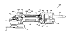
- FIG. 10 is a longitudinal sectional view showing a conventional disc grinder 101 shown in Patent Document 1.
- the disc grinder 101 has a motor housing 102 that houses a motor 105 that is a drive source.
- a separate tail cover 104 having a plurality of intake holes 119 is provided at the rear of the motor housing 102.
- the tail cover 104 turns on / off the power cord 130 connected to the outside and the power of the disc grinder 101.
- a power switch 107 is provided.
- a gear case 103 is provided in front of the motor housing 102.
- the gear case 103 houses drive transmission means for converting the power transmission direction of the motor rotation shaft by about 90 degrees.
- a grindstone 70 is attached to a spindle 111 that extends vertically in the gear case 103.
- the rotary shaft 105 c is rotatably held by a front bearing 118 a fixed to the gear case 103 and a rear bearing 118 b fixed to the main body housing 102.
- a cooling fan 110 is provided between the bearing 118a of the rotating shaft 105c and the motor 105.
- a brushless DC motor is a DC (direct current) motor without a brush (rectifying brush), and a coil (armature winding) is provided on the stator side, and a permanent magnet is used as a field means on the rotor side, which is driven by an inverter device.
- the rotor is rotated by sequentially energizing the predetermined power to a predetermined coil.
- the switching elements 133 and 136 constituting the inverter device for example, an FET (Field Effect Transistor) that is a semiconductor element is used.
- a rectifier circuit 139 is provided, and the rectified direct current is input to the inverter device.
- the switching element 133 is disposed on the front side of the inverter circuit board 132, and the switching element 136 is disposed on the rear side of the inverter circuit board 132.
- a position detection element 138 made of a Hall IC is further mounted on the front surface of the inverter circuit board 132.
- a sensor magnet 121 is attached to the rear end of the rotating shaft 105c.
- the sensor magnet 121 is a circular magnet attached to the rear end of the rotating shaft 105c in order to detect the rotational position of the rotor 105a, and is formed in the order of the NSNS poles at intervals of 90 degrees in the circumferential direction.
- the inverter circuit board 132 is provided perpendicular to the rotating shaft 105 c so as to face the rear side of the sensor magnet 121.
- the position detection element 138 detects the rotational position of the rotor 105a by detecting the position of the rotating sensor magnet 121, and is disposed, for example, at every 60 ° in the rotational direction.
- a plurality of intake holes 119 are formed in the tail cover 104 portion in the vicinity of the switching elements 133 and 136, and the switching elements 133 and 136 are effectively cooled by the air sucked by the cooling fan 110 to cool the motor 105.
- switching elements 133 and 136 that are switching elements for turning on and off energization of a coil wound around a stator are arranged on the front side and the rear side of the inverter circuit board 132 behind the motor.
- a method of effectively dissipating the switching elements 133 and 136 using cooling air for cooling the motor 105 is formed by forming the intake holes 119 in the vicinity of the inverter circuit board 132.
- the heat generation of the switching elements 133 and 136 becomes large, so that it is necessary to further improve the heat dissipation.
- the present invention has been made in view of the above background, and an object of the present invention is to provide an electric tool having a short overall length by attaching large heat dissipating means to a switching element and efficiently disposing them in the housing. is there. Another object of the present invention is to provide an electric tool that uses one thick plate heat sink as a heat radiating means for a plurality of switching elements, and has a plurality of switching elements fixed to the heat sink to improve heat dissipation and assembly. It is to provide.
- a motor having a rotation shaft, a cooling fan that rotates by rotation of the rotation shaft, a motor and a cooling fan are accommodated, and a housing that extends in the direction of the rotation axis of the motor is accommodated in the housing.
- a control board disposed so as to intersect the rotation axis, a switch provided between the motor and the control board in the housing, for turning on / off the rotation of the motor, and provided on the control board.
- a heat sink that contacts the plurality of switching elements is provided, and the heat sink is disposed so as to extend in a direction perpendicular to the control board and in the rotation axis direction.
- the heat sink is a thick plate made of metal, and a part of the plurality of switching elements is fixed to one surface side of the heat sink, and the remaining switching elements are fixed to the other surface side of the heat sink.
- the electric tool further includes a battery pack that can be attached to and detached from the housing, and the control board is disposed so as to be sandwiched between the motor and the battery pack in the direction of the rotation axis.
- the housing has a motor accommodating portion and a diameter-enlarged portion for attaching the battery pack, the control board is accommodated in the enlarged-diameter portion, and the longitudinal dimension of the control board is larger than the diameter dimension of the motor. It was configured as follows.
- the switching element is configured to be in surface contact with the heat sink in a direction parallel to the rotation axis, and the dimension of the heat sink in the rotation axis direction is larger than the dimension of the switching element.
- the motor is a brushless DC motor, and three switching elements are arranged side by side on one side of the heat sink and three on the other side opposite to the one side.
- the switching element is fixed so as to be in direct surface contact with the heat sink or indirectly in contact with the heat sink.
- the horizontal dimension in which the switching elements of the heat sink are arranged is preferably larger than the height dimension of the housing orthogonal to the horizontal dimension.
- the housing has an intake hole that allows cooling air to flow into the housing as the cooling fan rotates, and an exhaust hole that discharges cooling air from the housing. In the flow of the cooling air in the housing, it is positioned upstream of the motor. Further, a rotational speed adjusting means that is electrically connected to the control board and can adjust or switch the rotational speed of the motor is provided, and the rotational speed adjusting means is arranged so as to overlap with the heat sink in the rotational axis direction.
- the switching element and the circuit board are accommodated in the rear end portion (expanded diameter portion) of the housing, only the brushless motor needs to be accommodated in the grip portion, and the grip portion is reduced in diameter. it can.
- the control circuit including the inverter circuit and the microcomputer is mounted on the control board, the electronic device can be effectively arranged at the rear end portion of the housing while realizing a grip portion having a small diameter.
- the switching element constituting the inverter circuit is fixed to a metal thick plate heat sink, the heat dissipation can be improved and the temperature rise of the switching element can be suppressed.
- FIG. 1 is a perspective view showing an overall shape of a disc grinder 1 according to an embodiment of the present invention. It is a fragmentary perspective view which shows the rear end bottom vicinity of the disk grinder 1 which concerns on the Example of this invention.
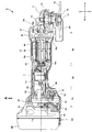
- 1 is a longitudinal sectional view of a disc grinder 1 according to an embodiment of the present invention.
- 3 is a block diagram showing a circuit configuration of a drive control system of a motor 5.
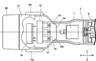
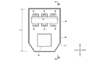
- FIG. It is the arrow view seen from the direction of the arrow A of FIG. 3, Comprising: It is the figure which showed a part with perspective drawing. It is a figure which shows the state which looked at the control board 31 from the front side of the rotating shaft direction of the motor.
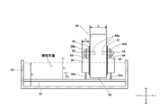
- FIG. 7 is a cross-sectional view taken along a line BB in FIG. 6.
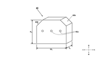
- FIG. 3 is a perspective view showing a single shape of a heat sink 40.
- FIG. It is a figure for demonstrating the arrangement
- FIG. It is a longitudinal cross-sectional view which shows the whole structure of the conventional disc grinder 101.
- FIG. 1 is a perspective view showing an overall shape of a disc grinder 1 which is an example of an electric tool according to an embodiment of the present invention.
- a housing (housing) of the disc grinder 1 includes a main body housing 2 that houses therein an electric motor that is a driving source, and a gear case 3 that is attached to the front of the main body housing 2.
- the main body housing 2 has a substantially cylindrical shape whose central axis extends in the front-rear direction.
- the main body housing 2 is provided between a portion for housing a motor, which will be described later, and a portion for holding the battery pack 60 (the enlarged diameter portion 2c).
- a grip portion (thin diameter portion) 2b with a small outer diameter (height and / or width) is formed, and is configured to be easily gripped by an operator.
- a switch lever 8 of a switch for turning on or off the rotation of the motor is provided on the side (left side surface) near the front end of the main body housing 2.
- the gear case 3 is fixed on the front side of the main body housing 2 by four screws 16 inserted from the front to the rear with the fan cover 17 interposed.
- the gear case 3 fixes a spindle (output shaft) to which the grindstone 70 is attached, and the grindstone 70 is connected via a rotation transmission mechanism (not shown) housed in the gear case 3 in conjunction with the rotation of the motor. Rotates.
- the grindstone 70 is, for example, a resinoid flexible toy having a diameter of 100 mm, a flexible toy, a resinoid toy, and a sanding disk. Depending on the type of abrasive used, surface grinding or curved surface grinding of metals, synthetic resins, marble, concrete, etc. is possible. is there.
- the rotational speed of the grindstone 70 can be adjusted to an arbitrary rotational speed of, for example, 1000 to 5000 rpm.
- a wheel guard 20 is provided around the rear side of the grindstone 70 to protect the operator from scattering of ground members and broken abrasive grains.
- a detachable side handle 4 is provided on one side surface (here, the right side) of the gear case 3.
- An intake hole 19b for sucking outside air by a cooling fan, which will be described later, is formed on both side surfaces near the rear end of the main body housing 2 on the front side surface of the main body housing 2, and the sucked air is discharged to the gear case 3.
- An exhaust hole 3a is provided.
- FIG. 2 is a partial perspective view showing the vicinity of the bottom surface of the rear end of the disc grinder 1 according to the embodiment of the present invention.
- a dial 9 for adjusting the rotational speed of the motor is provided on the rear side of the main body housing 2 and in the vicinity of the connection portion between the grip portion 2b and the enlarged diameter portion 2c.
- the dial 9 is a rotary type, and a number for indicating the speed level is printed on the dial.
- the rotational speed adjusting means of the motor 5 is not limited to the dial type adjusting means, but may be constituted by a changeover switch for switching between high and low, or may be set using an electronic switch. .
- a cover portion 2d for holding the battery pack 60 and closing an air hole formed in the battery pack 60 is provided behind and below the enlarged diameter portion 2c.
- a display panel 25 is provided in the cover 2d, and an AUTO button 26 and a battery remaining amount check button 27 are provided. Both of these can be configured with tactile switches.
- the AUTO button 26 is a button for setting the control method to the automatic transmission mode. When the automatic transmission mode is set, the number of rotations of the motor 5 is reduced when no load is applied, and the normal (selected with the dial) is detected when the load is detected. Control to switch to the rotation speed is performed. When the remaining battery level check button 27 is pressed, the remaining battery level indicator lamp 28 is turned on in a form corresponding to the remaining battery level.
- the remaining battery level indicator lamp 28 is formed by a plurality of LEDs. For example, when the remaining battery level is large, all the LEDs are turned on, and the number of LEDs to be lit is reduced as the remaining battery level decreases. What is necessary is just to comprise.
- the latch 61 provided on both sides of the battery pack is pushed and moved in the removal direction indicated by the arrow in the figure.
- FIG. 3 is a longitudinal sectional view showing an internal configuration of the disc grinder 1 according to the embodiment of the present invention.
- the motor 5 has an elongated shape in the axial direction (front-rear direction).
- a three-phase brushless DC motor is used as the motor 5.
- the motor 5 includes a stator 5b having a substantially cylindrical outer shape and a rotor 5a provided concentrically in the inner peripheral portion of the stator 5b.
- the motor 5 is manufactured by molding a polymer resin such as polycarbonate.
- the main body housing 2 is housed on the front side.
- the stator 5b of the motor 5 is fixed inside the main body housing 2, and the rotating shaft 5c is pivotally supported on the front side by a bearing 18a fixed to the fan cover 17 sandwiched between the gear case 3 and the main body housing 2.
- the rear side is pivotally supported by a bearing 18b fixed in the vicinity of the center of 2.
- a coil (armature winding) composed of three-phase windings U, V, and W is wound around the stator 5b.
- the rotor includes a metal rotor core attached to the outer peripheral side of the rotating shaft 5c, and a cylindrical magnet (permanent magnet) having N and S poles.
- a circular neodymium sintered magnet can be used to reduce the rotor diameter.
- a detection substrate 21 for mounting three position detection elements is provided between the stator 5b and the bearing 18b.
- the detection substrate 21 may be an annular or semicircular substrate having a through hole for allowing the rotation shaft 5c to pass therethrough, and position detection elements 22, 23, and 24 (see FIG. 4) are provided on the detection substrate 21.
- the position detection elements 22, 23, 24 detect the rotational position of the rotor 5a by detecting the position of the magnet of the rotating rotor 5a.
- a Hall IC is used, and every 60 ° in the rotational direction. Three are arranged.
- a switch 7 for rotating the motor 5 is provided behind the bearing 18 b and in the vicinity of the center of the main body housing 2.
- the switch 7 operates in conjunction with the switch lever 8 (see FIG. 1) to instruct turning on or off of the rotation of the motor 5.
- the switch 7 is turned on (connected state) or off ( 1-circuit 1-contact switch for switching to an intermittent state.
- the push button 7 a is operated by a link mechanism (not shown) that moves in conjunction with the movement of the switch lever 8.
- a cooling fan 10 is provided between the bearing 18a on the front side, the rotor 5a, and the stator 5b.
- the cooling fan 10 is a blower that rotates by the rotation of the rotating shaft 5c and generates an air flow from the rear intake hole 19b (see FIG. 2) to the front exhaust hole 3a.
- the air flow taken in from the outside of the main body housing 2 flows in the vicinity of the heat sink 40 as shown by the black arrow in the figure to cool the switching elements 33, 36, and then around the switch 7. Pass through and reach the motor 5.
- the cooling air passes through the gap between the outer periphery of the stator 5 b and the inner wall surface of the main body housing 2 and between the stator 5 b and the rotor 5 a and reaches the cooling fan 10. It is discharged forward from 3a to the outside of the housing.
- a detachable battery pack 60 is attached to the rear end of the main body housing 2.
- the battery pack 60 is a rechargeable secondary battery.
- a nickel cadmium battery, a nickel metal hydride battery, a lithium ion battery, or the like can be used.
- the battery pack 60 can be mounted so as to slide downward from the upper direction, and is fixed by the latch 61.
- the height dimension H B of the battery pack 60 is sufficiently larger than the diameter d m of the housing portion of the motor 5 of the main body housing 2.
- an enlarged-diameter portion 2 c is formed in the mounting portion of the main body housing 2 where the battery pack 60 is mounted.
- the enlarged diameter portion 2c is a portion in which the height direction and the width direction (left and right direction) of the main body housing 2 are formed larger than the diameter of the accommodating portion of the motor 5 of the main body housing 2, and the expanded internal space
- a control board 31 is arranged.
- the control board 31 is accommodated in the board case 32, arranged so that the surface of the control board 31 is orthogonal to the rotation axis direction of the motor 5 (longitudinal direction of the main body housing 2), and parallel to the slide surface of the battery pack 60. It is arranged to become.
- the control board 31 is equipped with six switching elements (33, 36, etc.) and a microcomputer (not shown) constituting the control means, but the switching element having a relatively large mounting space is connected to the motor 5 from the control board 31. It arrange
- the six switching elements (33, 36, etc.) are provided with a large heat sink 40 for cooling.
- the heat sink 40 can be composed of a thick plate made of metal, and the switching elements 33 and 36 are fixed to one surface (upper surface) and the other surface (lower surface) of the thick plate, respectively.
- a dial 9 for setting the rotational speed of the motor 5 is provided on the front side of the enlarged diameter portion 2 c of the main body housing 2.
- the dial 9 is rotatable about the rotating shaft 9a.
- the rotating shaft 9a is arranged in parallel with the rotating shaft direction of the motor 5, and most of the dial 9 except for a part of the outer peripheral portion is the main body housing 2.
- the dial 9 is a variable resistor and is connected to a control circuit.
- the main body housing 2 of the present embodiment has a divided structure that is divided into right and left from a vertical plane passing through the rotation axis of the motor 5, and the board case 32 and the dial 9 that accommodate the control board 31 are arranged on the right side of the main body housing. It is fixed so as to be sandwiched between holding parts (attachment ribs) formed on the inner wall of the left part.
- the gear case 3 is formed by integrally molding a metal such as aluminum, for example, and accommodates a power transmission mechanism using a pair of bevel gear mechanisms (bevel gears 12 and 13) and can rotate a spindle 14 serving as an output shaft. Hold.
- the spindle 14 extends so as to be orthogonal to the rotating shaft 5c (horizontal direction) of the motor 5, and the wheel nut 15 fixed from the lower side of the grindstone 70 with a spanner (not shown) is removed to remove the grindstone 70. Can be exchanged.
- the cooling fan 10 When the motor 5 rotates, the cooling fan 10 generates an air flow from the rear to the front inside the main body housing 2.
- a part of the flow of the air flow is indicated by arrows, and the heat sink 40 is upstream of the motor 5 in the flow of the cooling air in the main body housing and the switch 7 and the battery pack 60. Located between.
- the motor 5 is a three-phase brushless DC motor.
- This brushless DC motor is a so-called inner rotor type, and is star-connected to a rotor 5a including a plurality of sets (two sets in this embodiment) of permanent magnets (magnets) including N poles and S poles.
- a stator 5b composed of three-phase stator windings U, V, and W.
- the arithmetic unit 51 is a central processing unit (CPU) for outputting a drive signal based on the processing program and data, a ROM for storing the processing program and control data, and for temporarily storing data.
- the RAM, the timer, and the like are included, and the rotational speed of the motor 5 is controlled.
- the rotation speed of the motor 5 can be arbitrarily set by the dial 9, and the calculation unit 51 starts or stops the motor 5 according to the operation of the switch 7 by the operator.
- the inverter circuit means is mainly composed of six switching elements 33 to 38 such as FETs connected in a three-phase bridge form.
- the gates of the six switching elements 33 to 38 that are bridge-connected are connected to the control signal output circuit 52, and the drains or sources of the six switching elements 33 to 38 are the stator windings U, V, and W. Connected to.
- the six switching elements 33 to 38 perform a switching operation by the switching element drive signals (drive signals such as H4, H5, H6, etc.) input from the control signal output circuit 52, and are applied to the inverter circuit means.
- the direct current of the battery pack 60 is converted into three-phase (U-phase, V-phase and W-phase) AC voltages Vu, Vv and Vw, and the driving power of the motor 5 is supplied to the stator windings U, V and W.
- the three negative power supply side switching elements 36 to 38 are connected to pulse width modulation signals (PWM signals) H4, H5,
- PWM signals pulse width modulation signals
- the operation unit 51 supplied as H6 and mounted on the control board 31 starts power supply to the motor 5 based on the output signals of the position detection elements 22 to 24 constituting the switch means of the motor 5.
- the PWM signal is supplied to the negative power supply side switching elements 36 to 38 of the inverter circuit means.
- the operation state of the switch 7 is detected by the switch operation detection circuit 56, and the switch operation detection circuit 56 outputs either high (switch ON) or low (switch OFF) output to the calculation unit 51.
- the output of the dial 9 for adjusting the rotational speed of the motor 5 is input to the rotational speed setting circuit 57, and the rotational speed setting circuit 57 sends a control signal corresponding to the set position of the dial 9 to the calculation unit 51.
- the calculation unit 51 forms a drive signal for alternately switching predetermined switching elements 33 to 38 based on the output signals of the switch operation detection circuit 56 and the rotation speed setting circuit 57, and the drive signal of the motor 5 is used as a control signal. Output to the output circuit 52.
- the predetermined windings of the stator windings U, V, and W are alternately energized, and the rotor 5a is rotated at a set rotational speed.
- the rotation speed of the motor 5 is detected by the rotation speed detection circuit 54 using the output of the rotor position detection circuit 53 that detects the outputs of the position detection elements 22 to 24. Both the outputs of the rotor position detection circuit 53 and the rotation speed detection circuit 54 are output to the calculation unit 51.
- the current value supplied to the motor 5 is measured by the current detection circuit 55, and the value is fed back to the calculation unit 51, so that the calculation unit 51 adjusts the set drive power to the motor 5. Rotation control is performed.
- FIG. 5 is an arrow view from the direction of the arrow A in FIG. 3 and most of the figure is a perspective view.
- the switching elements 33 to 35 are screwed in a state of being arranged in a line on the front side (upper side surface) of the common heat sink 40. At this time, it is important to fix the switching elements 33 to 35 so as to have a predetermined interval so as not to contact each other. Although not visible in FIG.
- the switching elements 36 to 38 are similarly screwed to the back side (lower side) of the heat sink 40, and the switching elements 33 to 35 and the switching elements 36 to 38 are positioned symmetrically. Placed in.
- an aluminum plate having a thickness of about 10 mm is used in this embodiment. The surface of the aluminum plate extends in the front-rear direction and the left-right direction, and is disposed so as to be perpendicular to the control board 31. In other words, the heat sink 40 is disposed so as to extend in the direction of the rotation axis from the control board 31 toward the motor 5 side.
- the heat sink 40 has an inclined surface portion 40b whose front end corner portion is formed obliquely along the inner wall surface of the main body housing 2 and effectively uses the space in the main body housing 2 by dropping corners.
- a terminal holder 39 is provided on the rear side of the substrate case 32 in order to fix a plurality of terminals (not shown) for making contact with the connection terminals of the battery pack 60.
- Air intake holes 19 a and 19 b are provided on the left and right side surfaces of the enlarged diameter portion 2 c of the main body housing 2. In FIG. 5, in order to attach a filter device (not shown) to the intake holes 19a and 19b, it has a shape that protrudes to the outside.
- the cooling air flows in substantially the same direction as the direction in which the heat sink 40 extends, and an air flow that does not impede the flow of the heat sink 40 can be created.
- the cooling air strikes the upper, lower, left and right side surfaces of the heat sink 40, the heat sink 40 and the switching elements 33 to 38 can be efficiently cooled. Since the heat sink 40 is configured in this way, the switching element 33 is effectively provided while the grip portion 2b having a smaller diameter than the motor housing portion 2a is provided on the rear side of the motor housing portion 2a that houses the motor 5. It became possible to cool ⁇ 38.
- FIG. 6 is a diagram illustrating a state in which the control board 31 is viewed from the front side in the rotation axis direction of the motor.
- the control board 31 is fixed inside a board case 32 made of synthetic resin.
- three switching elements 33 to 35 are brought into surface contact with one surface (upper surface) of an aluminum alloy heat sink 40 having a thickness Ta, and three switching elements are disposed on the other surface (lower surface) facing one surface (upper surface).
- 36 to 38 were brought into surface contact side by side.
- the switching elements 33 to 35 and 36 to 38 are preferably fixed to the heat sink 40 via an insulating sheet (not shown in FIG. 6, described later in FIG. 7).
- the longitudinal dimension (length Lc) of the control board 31 is sufficiently larger than the diameter of the stator 5b of the motor 5, and an electronic element such as the microcomputer 51 is preferably mounted on the enlarged portion.
- the substrate case 32 is formed in a substantially rectangular parallelepiped container shape having an opening surface on the upper side, and a control substrate 31 on which switching elements 33 to 38 are mounted is accommodated.
- the heat sink 40 which is a metal thick plate, is positioned so as to have a gap 46 slightly away from the control board 31. Since the heat sink 40 is a conductor, a gap 46 is provided so as not to short-circuit the terminals of the control board 31.
- the switching elements 33 to 38 are well-known FETs (field effect transistors), have three terminals 35a and 38a of a source, a drain, and a gate, and are made of metal so as to extend partly from the back of the main body and upward from the back.
- the heat sinks 35b and 38b having the screw holes are provided.
- the heat sinks 35b and 38b are respectively screwed into the screw holes 40a formed in the heat sink 40 by screws 43.
- the heat sink 40 and the heat sinks 35b and 38b are electrically insulated so that they are electrically insulated. It is fixed with a sleeve 44 interposed. At this time, the screw 43 that stops the heat sink 35b and the screw 43 that stops the heat sink 38b are located on the same axis.
- a heat conductive but electrically insulating resin sheet 41 is interposed between the switching elements 35, 38 and the heat sink 40, and the switching elements 35, 38, while maintaining good heat dissipation.
- the heat sink 40 is configured not to be electrically short-circuited. Dimension in the rotation axis direction (longitudinal direction) of the heat sink 40 may be understood to be sufficiently larger than the size F T of the switching elements 35 and 38.
- the switching elements 33 to 34 and 36 to 37 are also fixed to the heat sink 40 by the same method. By using such a fixing method, the six switching elements 33 to 38 could be fixed to one heat sink 40.
- the control board 31 on which the switching elements 33 to 38 and other electronic elements including the microcomputer 51 (not shown in FIG. 7) are mounted is filled with a waterproof / insulating resin such as silicon and hardened. did.
- the opening of the container-like substrate case 32 faces upward, and the liquid resin is filled from the inner bottom surface to the position of a one-dot chain line having a height H and solidified.
- the height H it is important to be configured to be higher than the length F B of after mounting the terminal (leg) 35a of the control board 31 of the switching element 35.
- the terminal (leg) 35a By higher than the length F B of the height H of the resin to be filled in this way the terminal (leg) 35a, it can effectively prevent damage to the switching elements 33-38 due to vibration during operation of the power tool The life of the electric tool can be extended.
- the height H was lower than F T (upper end position of the ceramic package) the height of the main body portion after attachment to the control board 31 of the switching element 35.
- F T upper end position of the ceramic package
- the heat radiating plate 35b extending above the upper end position of the ceramic package is exposed to the outside of the resin, so that the heat radiating plate 35b is exposed to the air flow generated by the cooling fan 10, which is favorable. Heat dissipation can be realized.
- the heat sink 40 is partially located inside the resin, most of the heat sink 40 is exposed to the outside from the resin. Therefore, the heat sink 40 is firmly fixed so as not to be rattled by the resin. The effect of being cooled well by the flow is obtained.
- the thickness of the switching element 38 is T f
- the thickness of the heat sink 40 corresponding thereto is configured to be equal to or greater than the 2T f.
- the heat sink 40 having such a thickness, it becomes easy to fix the switching elements on both surfaces using the screws 43, and the screw holes 40a can be formed.
- the heat sink 40 is aluminum, it is lightweight and can be manufactured at a relatively low cost, while having a sufficient heat capacity, it is possible to achieve good heat dissipation performance.
- FIG. 40 Various shapes of the heat sink 40 are conceivable, and various shapes such as those having a complicated fin shape using aluminum extrusion molding may be used.
- a simple light metal alloy thick plate is used, and six screw holes 40a are formed on both sides thereof.
- the screw hole 40a is arranged such that another screw hole 40a is arranged on the opposite side, and the two screw holes 40a facing each other are located on the same axis.
- three screw holes 40a are formed on one surface, and a line connecting the three screw holes 40a extends in the left-right direction orthogonal to the rotation shaft 5c. This arrangement improves the weight balance between the top, bottom, left and right.
- the width Wa of the heat sink 40 may be 41 mm
- the plate thickness Ta is 10 mm
- the height Ha is about 43 mm.
- the two screw holes 40a facing each other may be positioned on the same axis or shifted in a relatively arbitrary manner, and is not limited to the arrangement of the present embodiment.
- the dial 9 is provided in a portion 48 sandwiched at right angles in the L-shaped space 47.
- This relationship is a positional relationship in which the front-rear position Sa occupied by the heat sink 40 and the front-rear position Sd occupied by the dial 9 overlap in the vertical direction, that is, in a direction intersecting with the direction along the rotation shaft 5c.
- the rotation speed adjusting means (the dial 9 or the like) is arranged so as to overlap the heat sink 40 in the direction of the rotation axis (longitudinal direction of the main body housing 2).
- the plate thickness Ta (see FIG. 7) of the heat sink 40 is smaller than the height dimension Hh of the L-shaped space 47
- the width Wa (see FIG. 6) of the heat sink 40 is the height dimension of the L-shaped space 47.
- Hh the height of the inner wall portion of the main body housing 2 near the front and rear center of the heat sink 40. That is, the horizontal dimension (width Wa) in which the switching elements 33 to 38 of the heat sink 40 are lined up is larger than the height dimension (Hh) of the housing orthogonal thereto.
- this invention is not limited to the above-mentioned Example, A various change is possible within the range which does not deviate from the meaning.
- a method of detecting the position of the rotor magnet using a position detection element but a so-called sensorless method in which the rotor position is detected by extracting the induced voltage (back electromotive force) of the coil of the stator 5b as a logical signal through a filter.
- a secondary battery pack is used as a power source.
- an AC power source and a rectifier circuit may be used as in the conventional example.
- a power supply circuit board may be further provided on the rear side of the control board 31, and a full-wave rectification circuit using a diode bridge and a capacitor for converting alternating current into direct current may be mounted.
- the present invention is not limited to the disk grinder, and may be applied to other electric tools that drive the motor using an inverter circuit. .
Landscapes
- Engineering & Computer Science (AREA)
- Mechanical Engineering (AREA)
- Portable Power Tools In General (AREA)
Abstract
Description
Claims (9)
- 回転軸を有するモータと、前記回転軸の回転により回転する冷却ファンと、前記モータ及び前記冷却ファンを収容し、前記モータの回転軸方向に延びるハウジングと、前記ハウジングに収容され、前記回転軸と交差するように配置される制御基板と、前記ハウジング内において、前記モータと前記制御基板との間に設けられ前記モータの回転のオン又はオフを指示するスイッチと、前記制御基板に設けられ、前記モータへの通電を制御する複数のスイッチング素子と、前記複数のスイッチング素子と接触するヒートシンクとを有し、前記ヒートシンクは前記制御基板に直交する方向であって前記回転軸方向に延びるように配置されることを特徴とする電動工具。
- 前記ヒートシンクは金属製の厚板であって、前記複数のスイッチング素子の一部が前記ヒートシンクの一面側に固定され、残りの前記スイッチング素子が前記ヒートシンクの他面側に固定されることを特徴とする請求項1に記載の電動工具。
- 前記ハウジングに着脱可能な電池パックをさらに有し、前記制御基板は、前記回転軸方向にみて前記モータと前記電池パックとに挟まれるように配置されることを特徴とする請求項1又は2に記載の電動工具。
- 前記ハウジングは、前記モータを収容する部分と前記電池パックを取り付けるための拡径部を有し、前記制御基板は前記拡径部に収容され、前記制御基板の長手方向の寸法は前記モータの径寸法よりも大きいことを特徴とする請求項3に記載の電動工具。
- 前記スイッチング素子は、前記回転軸と平行な方向において、前記ヒートシンクに面接触され、前記回転軸方向における前記ヒートシンクの寸法は前記スイッチング素子の寸法よりも大きいことを特徴とする請求項1から4のいずれか一項に記載の電動工具。
- 前記モータはブラシレスDCモータであり、前記スイッチング素子は、前記ヒートシンクの一面に3つ、前記一面に対向する他面に3つ並んで面接触させることを特徴とする請求項5に記載の電動工具。
- 前記ヒートシンクの前記スイッチング素子が並ぶ横方向の寸法は、これに直交する前記ハウジングの高さ寸法よりも大きいことを特徴とする請求項6に記載の電動工具。
- 前記ハウジングは、前記冷却ファンが回転することにより前記ハウジング内に冷却風を流入させる吸気孔と、排気孔とを有し、前記ヒートシンクは、前記ハウジング内における前記冷却風の流れにおいて、前記モータよりも上流側に位置することを特徴とする請求項1から7のいずれか一項に記載の電動工具。
- 前記制御基板に電気的に接続され、前記モータの回転速度を調整可能な回転速度調整手段を有し、前記回転速度調整手段は、前記回転軸方向において、前記ヒートシンクとオーバーラップするように配置されていることを特徴とする請求項1から8のいずれか一項に記載の電動工具。
Priority Applications (3)
| Application Number | Priority Date | Filing Date | Title |
|---|---|---|---|
| CN201580068604.2A CN107107326B (zh) | 2014-12-18 | 2015-11-27 | 电动工具 |
| DE112015005645.9T DE112015005645T5 (de) | 2014-12-18 | 2015-11-27 | Elektrowerkzeug |
| JP2016564764A JP6460123B2 (ja) | 2014-12-18 | 2015-11-27 | 電動工具 |
Applications Claiming Priority (2)
| Application Number | Priority Date | Filing Date | Title |
|---|---|---|---|
| JP2014256504 | 2014-12-18 | ||
| JP2014-256504 | 2014-12-18 |
Publications (1)
| Publication Number | Publication Date |
|---|---|
| WO2016098564A1 true WO2016098564A1 (ja) | 2016-06-23 |
Family
ID=56126461
Family Applications (1)
| Application Number | Title | Priority Date | Filing Date |
|---|---|---|---|
| PCT/JP2015/083427 Ceased WO2016098564A1 (ja) | 2014-12-18 | 2015-11-27 | 電動工具 |
Country Status (4)
| Country | Link |
|---|---|
| JP (1) | JP6460123B2 (ja) |
| CN (1) | CN107107326B (ja) |
| DE (1) | DE112015005645T5 (ja) |
| WO (1) | WO2016098564A1 (ja) |
Cited By (6)
| Publication number | Priority date | Publication date | Assignee | Title |
|---|---|---|---|---|
| JP2018171680A (ja) * | 2017-03-31 | 2018-11-08 | 工機ホールディングス株式会社 | 電動工具 |
| JP2019162676A (ja) * | 2018-03-19 | 2019-09-26 | 京セラインダストリアルツールズ株式会社 | 電動工具 |
| DE102019131651A1 (de) | 2018-11-28 | 2020-05-28 | Makita Corporation | Elektrische arbeitsmaschine mit halbleiterelement, das einen stromweg zu einem motor schliesst oder unterbricht |
| JP2020163568A (ja) * | 2017-03-31 | 2020-10-08 | 株式会社マキタ | 電動工具 |
| WO2021161623A1 (ja) * | 2020-02-10 | 2021-08-19 | 株式会社マキタ | 電動工具用コントローラ及び電動工具 |
| JP2022075561A (ja) * | 2020-11-04 | 2022-05-18 | 朝程工業股▲フン▼有限公司 | 電動工具 |
Families Citing this family (3)
| Publication number | Priority date | Publication date | Assignee | Title |
|---|---|---|---|---|
| CN110614563B (zh) * | 2018-06-20 | 2024-04-30 | 南京泉峰科技有限公司 | 打磨工具 |
| JP7193412B2 (ja) * | 2019-04-22 | 2022-12-20 | 株式会社マキタ | 作業工具 |
| CN213661375U (zh) * | 2020-11-17 | 2021-07-09 | 东莞市力宸机电科技有限公司 | 一种电机模组及应用该电机模组的电动工具 |
Citations (4)
| Publication number | Priority date | Publication date | Assignee | Title |
|---|---|---|---|---|
| JP2009285787A (ja) * | 2008-05-29 | 2009-12-10 | Hitachi Koki Co Ltd | 電動工具 |
| US20100009608A1 (en) * | 2008-07-08 | 2010-01-14 | Lo Ping-Hsiang | Electric polishing gun |
| JP2012020363A (ja) * | 2010-07-14 | 2012-02-02 | Hitachi Koki Co Ltd | 電動工具 |
| US20140361645A1 (en) * | 2013-06-06 | 2014-12-11 | Milwaukee Electric Tool Corporation | Brushless dc motor configuration for a power tool |
Family Cites Families (6)
| Publication number | Priority date | Publication date | Assignee | Title |
|---|---|---|---|---|
| JP4398212B2 (ja) * | 2003-09-22 | 2010-01-13 | 日本電産シバウラ株式会社 | 電動工具用自冷式モータ |
| JP5589255B2 (ja) * | 2008-02-26 | 2014-09-17 | 日立工機株式会社 | 携帯用電動工具 |
| JP5287068B2 (ja) * | 2008-09-12 | 2013-09-11 | 日立工機株式会社 | 電動工具 |
| EP2391480B2 (en) * | 2009-01-30 | 2018-08-15 | Koki Holdings Kabushiki Kaisha | Power tool |
| JP5424018B2 (ja) * | 2009-01-30 | 2014-02-26 | 日立工機株式会社 | 電動工具 |
| CN104148699A (zh) * | 2014-07-28 | 2014-11-19 | 宁波市鄞州多凡国际贸易有限公司 | 一种墙壁钻孔电钻 |
-
2015
- 2015-11-27 WO PCT/JP2015/083427 patent/WO2016098564A1/ja not_active Ceased
- 2015-11-27 DE DE112015005645.9T patent/DE112015005645T5/de active Pending
- 2015-11-27 CN CN201580068604.2A patent/CN107107326B/zh active Active
- 2015-11-27 JP JP2016564764A patent/JP6460123B2/ja active Active
Patent Citations (4)
| Publication number | Priority date | Publication date | Assignee | Title |
|---|---|---|---|---|
| JP2009285787A (ja) * | 2008-05-29 | 2009-12-10 | Hitachi Koki Co Ltd | 電動工具 |
| US20100009608A1 (en) * | 2008-07-08 | 2010-01-14 | Lo Ping-Hsiang | Electric polishing gun |
| JP2012020363A (ja) * | 2010-07-14 | 2012-02-02 | Hitachi Koki Co Ltd | 電動工具 |
| US20140361645A1 (en) * | 2013-06-06 | 2014-12-11 | Milwaukee Electric Tool Corporation | Brushless dc motor configuration for a power tool |
Cited By (12)
| Publication number | Priority date | Publication date | Assignee | Title |
|---|---|---|---|---|
| JP2018171680A (ja) * | 2017-03-31 | 2018-11-08 | 工機ホールディングス株式会社 | 電動工具 |
| JP2020163568A (ja) * | 2017-03-31 | 2020-10-08 | 株式会社マキタ | 電動工具 |
| JP7027490B2 (ja) | 2017-03-31 | 2022-03-01 | 株式会社マキタ | 電動工具 |
| JP2019162676A (ja) * | 2018-03-19 | 2019-09-26 | 京セラインダストリアルツールズ株式会社 | 電動工具 |
| JP7212826B2 (ja) | 2018-03-19 | 2023-01-26 | 京セラインダストリアルツールズ株式会社 | 電動工具 |
| DE102019131651A1 (de) | 2018-11-28 | 2020-05-28 | Makita Corporation | Elektrische arbeitsmaschine mit halbleiterelement, das einen stromweg zu einem motor schliesst oder unterbricht |
| CN111230815A (zh) * | 2018-11-28 | 2020-06-05 | 株式会社牧田 | 电动作业机 |
| US11777377B2 (en) | 2018-11-28 | 2023-10-03 | Makita Corporation | Electric working machine with semiconductor element that completes or interrupts current path to motor |
| CN111230815B (zh) * | 2018-11-28 | 2023-10-13 | 株式会社牧田 | 电动作业机 |
| WO2021161623A1 (ja) * | 2020-02-10 | 2021-08-19 | 株式会社マキタ | 電動工具用コントローラ及び電動工具 |
| JP2022075561A (ja) * | 2020-11-04 | 2022-05-18 | 朝程工業股▲フン▼有限公司 | 電動工具 |
| JP7168177B2 (ja) | 2020-11-04 | 2022-11-09 | 朝程工業股▲フン▼有限公司 | 電動工具 |
Also Published As
| Publication number | Publication date |
|---|---|
| CN107107326B (zh) | 2020-06-30 |
| JP6460123B2 (ja) | 2019-01-30 |
| CN107107326A (zh) | 2017-08-29 |
| DE112015005645T5 (de) | 2017-08-31 |
| JPWO2016098564A1 (ja) | 2017-08-31 |
Similar Documents
| Publication | Publication Date | Title |
|---|---|---|
| JP6460123B2 (ja) | 電動工具 | |
| JP6288270B2 (ja) | 電動工具 | |
| JP6443541B2 (ja) | 電動工具 | |
| JP6288271B2 (ja) | 電動工具 | |
| JP5472683B2 (ja) | 電動工具 | |
| US9314900B2 (en) | Handheld grinder with a brushless electric motor | |
| US20110180286A1 (en) | Electric Power Tool | |
| JP5370916B2 (ja) | 電動工具 | |
| US20170274520A1 (en) | Power tool having an elongated housing supporting a power module | |
| JPWO2018198671A1 (ja) | 電動工具 | |
| JP2011161605A (ja) | 電動工具 | |
| JP6627278B2 (ja) | 電動工具 | |
| US12381448B2 (en) | Handheld power tool with a brushless electric motor | |
| WO2017082082A1 (ja) | 電動工具 | |
| JP6627250B2 (ja) | 電動工具 | |
| JP7278063B2 (ja) | 電動工具 | |
| JP2017013142A (ja) | 電動工具 | |
| JP2021133477A (ja) | 動力工具 | |
| JP2017017770A (ja) | 電動工具 | |
| WO2016002542A1 (ja) | 電動工具 | |
| JP6497237B2 (ja) | 電動工具 |
Legal Events
| Date | Code | Title | Description |
|---|---|---|---|
| 121 | Ep: the epo has been informed by wipo that ep was designated in this application |
Ref document number: 15869772 Country of ref document: EP Kind code of ref document: A1 |
|
| ENP | Entry into the national phase |
Ref document number: 2016564764 Country of ref document: JP Kind code of ref document: A |
|
| WWE | Wipo information: entry into national phase |
Ref document number: 112015005645 Country of ref document: DE |
|
| 122 | Ep: pct application non-entry in european phase |
Ref document number: 15869772 Country of ref document: EP Kind code of ref document: A1 |