WO2016092947A1 - 紙葉類鑑別装置 - Google Patents
紙葉類鑑別装置 Download PDFInfo
- Publication number
- WO2016092947A1 WO2016092947A1 PCT/JP2015/078543 JP2015078543W WO2016092947A1 WO 2016092947 A1 WO2016092947 A1 WO 2016092947A1 JP 2015078543 W JP2015078543 W JP 2015078543W WO 2016092947 A1 WO2016092947 A1 WO 2016092947A1
- Authority
- WO
- WIPO (PCT)
- Prior art keywords
- ultraviolet
- paper sheet
- ultraviolet sensor
- sensor
- light
- Prior art date
Links
- OAICVXFJPJFONN-UHFFFAOYSA-N Phosphorus Chemical compound [P] OAICVXFJPJFONN-UHFFFAOYSA-N 0.000 claims abstract description 41
- 230000005284 excitation Effects 0.000 claims abstract description 27
- 230000001678 irradiating effect Effects 0.000 claims abstract description 4
- 230000003287 optical effect Effects 0.000 claims description 54
- 238000003860 storage Methods 0.000 claims description 18
- 230000005540 biological transmission Effects 0.000 claims description 9
- 238000003780 insertion Methods 0.000 claims description 6
- 230000037431 insertion Effects 0.000 claims description 6
- 230000002093 peripheral effect Effects 0.000 claims description 6
- 238000011144 upstream manufacturing Methods 0.000 claims description 4
- 230000007246 mechanism Effects 0.000 claims description 3
- 230000000903 blocking effect Effects 0.000 claims description 2
- 230000005855 radiation Effects 0.000 abstract 6
- 238000006243 chemical reaction Methods 0.000 description 72
- 238000001514 detection method Methods 0.000 description 31
- 230000032258 transport Effects 0.000 description 29
- 239000002775 capsule Substances 0.000 description 16
- 238000004519 manufacturing process Methods 0.000 description 16
- 238000010586 diagram Methods 0.000 description 11
- 238000006073 displacement reaction Methods 0.000 description 10
- 239000000758 substrate Substances 0.000 description 10
- 239000000428 dust Substances 0.000 description 8
- 239000011347 resin Substances 0.000 description 7
- 229920005989 resin Polymers 0.000 description 7
- 230000003321 amplification Effects 0.000 description 5
- 238000000034 method Methods 0.000 description 5
- 238000003199 nucleic acid amplification method Methods 0.000 description 5
- 230000000052 comparative effect Effects 0.000 description 4
- 230000006835 compression Effects 0.000 description 4
- 238000007906 compression Methods 0.000 description 4
- 230000000694 effects Effects 0.000 description 4
- 230000008569 process Effects 0.000 description 4
- 230000001360 synchronised effect Effects 0.000 description 4
- 239000013013 elastic material Substances 0.000 description 3
- 239000000463 material Substances 0.000 description 3
- 239000007769 metal material Substances 0.000 description 3
- 238000005192 partition Methods 0.000 description 3
- 230000003247 decreasing effect Effects 0.000 description 2
- 238000000605 extraction Methods 0.000 description 2
- 230000002452 interceptive effect Effects 0.000 description 2
- 238000012423 maintenance Methods 0.000 description 2
- 238000012856 packing Methods 0.000 description 2
- 239000000843 powder Substances 0.000 description 2
- 229910000963 austenitic stainless steel Inorganic materials 0.000 description 1
- 238000004061 bleaching Methods 0.000 description 1
- 238000005520 cutting process Methods 0.000 description 1
- 238000001917 fluorescence detection Methods 0.000 description 1
- 238000012986 modification Methods 0.000 description 1
- 230000004048 modification Effects 0.000 description 1
- 238000003825 pressing Methods 0.000 description 1
- 238000012545 processing Methods 0.000 description 1
- 238000007789 sealing Methods 0.000 description 1
Images


Classifications
-
- G—PHYSICS
- G07—CHECKING-DEVICES
- G07D—HANDLING OF COINS OR VALUABLE PAPERS, e.g. TESTING, SORTING BY DENOMINATIONS, COUNTING, DISPENSING, CHANGING OR DEPOSITING
- G07D7/00—Testing specially adapted to determine the identity or genuineness of valuable papers or for segregating those which are unacceptable, e.g. banknotes that are alien to a currency
- G07D7/06—Testing specially adapted to determine the identity or genuineness of valuable papers or for segregating those which are unacceptable, e.g. banknotes that are alien to a currency using wave or particle radiation
- G07D7/12—Visible light, infrared or ultraviolet radiation
Definitions
- the present disclosure relates to a paper sheet discrimination device that discriminates paper sheets.
- a cash handling device such as an automatic teller machine (ATM) or a cash dispenser (CD) is equipped with a paper sheet discrimination device for differentiating the denomination and authenticity of paper sheets (banknotes) used. Has been.
- ATM automatic teller machine
- CD cash dispenser
- the paper sheet discrimination device includes a magnetic sensor that acquires magnetic information of a paper sheet, an optical image sensor that acquires image information of a paper sheet, a thickness detection sensor that acquires thickness information of the paper sheet, and the like. ing.
- the paper sheet discriminating apparatus discriminates the number of paper sheets, the running state, the denomination, the authenticity, the degree of damage (loss), and the like based on various information acquired by these sensors.
- denomination banknotes that are provided with a phosphor that emits excitation light when irradiated with ultraviolet light.
- a region that is excited by being irradiated with ultraviolet light and emits excitation light is referred to as an “ultraviolet phosphor region”.
- the phenomenon in which the phosphor is irradiated with ultraviolet light and emits excitation light is referred to as “ultraviolet light fluorescence reaction”.
- UV sensor ultraviolet sensor
- An ultraviolet sensor is a sensor that detects an ultraviolet light fluorescence reaction of a paper sheet when the paper sheet (banknote) is irradiated with ultraviolet light.
- a paper sheet discrimination device described in Japanese Patent Application Laid-Open No. 2013-206440 uses an ultraviolet sensor (UV sensor) to irradiate a paper sheet (banknote) with ultraviolet light and reflect or reflect light. , And the result is acquired as ultraviolet sensor information, and the reflected image information is acquired by irradiating the paper with visible light and reading the reflected light with an optical image sensor (line image sensor).
- UV sensor ultraviolet sensor
- line image sensor optical image sensor
- a paper sheet discrimination device described in Japanese Patent Application Laid-Open No. 2009-157504 irradiates a paper sheet with ultraviolet light emitted by a light emitting unit (ultraviolet light emitting lamp) of an ultraviolet sensor (fluorescence emission detecting unit), and The excitation light emitted from the phosphor when the phosphor contained in the leaf is excited by ultraviolet light is received by the light receiving unit (photodiode), and the bleaching emission characteristic and the fluorescence emission characteristic from the paper are obtained. .
- the paper sheet discrimination apparatus comprehensively uses the fluorescence reaction information of paper sheets acquired by the ultraviolet sensor and the characteristic information of various paper sheets acquired by other sensors, thereby The discrimination accuracy such as the number of sheets, running state, denomination, authenticity, degree of damage (loss) is improved.
- an authentic paper sheet (genuine bill) has an ultraviolet phosphor region only on a part of the paper surface.
- various fake paper sheets there are paper sheets that have an ultraviolet phosphor region over the entire surface of the paper.
- Such a fake note is presumed to be manufactured by using paper sheets such as copy paper (quality paper) without performing special processing that limits the ultraviolet phosphor region, for example. .
- Such a counterfeit note (hereinafter referred to as a “counterfeit note”) has an ultraviolet phosphor region in all parts of the paper surface, so that the ultraviolet light fluorescence reaction is detected from all parts of the paper surface.
- a characteristic is a characteristic that a genuine note cannot originally have.
- the paper sheet discrimination apparatus described in Japanese Patent Application Laid-Open No. 2013-206440 or Japanese Patent Application Laid-Open No. 2009-157504 has only a single ultraviolet sensor. Therefore, these paper sheet discrimination devices discriminate between genuine bills and counterfeit bills only by discriminating whether or not an ultraviolet light fluorescence reaction is detected from the paper surface of the paper sheets in discrimination using ultraviolet light. I can't.
- the paper sheet discrimination device in the discrimination using ultraviolet light, the paper sheet to be identified is a fake note, and the ultraviolet light fluorescence reaction is detected from the entire part of the paper surface of the paper sheet. Even so, the paper sheet could not be properly identified as a fake ticket.
- the inventor of the present disclosure uses a plurality of (for example, two) ultraviolet sensors so that the plurality of ultraviolet sensors do not interfere with each other, and the ultraviolet light fluorescence reaction starts from only a specific part of the paper surface. It was thought that such a problem could be solved by determining whether or not it was detected.
- This disclosure mainly aims to provide a paper sheet discrimination apparatus that improves the authenticity discrimination performance of paper sheets in discrimination using ultraviolet light in order to solve the above problems.
- the present disclosure is a paper sheet discrimination device that discriminates paper sheets, a transport member that transports paper sheets, and a transport member that is disposed to face the transport member, A sandwiching member that sandwiches the paper sheet therebetween, a first guide that supports the transport member, a second guide that is disposed opposite to the first guide and supports the sandwiching member, and the first A first ultraviolet sensor that is disposed on the guide side, irradiates the exterior with ultraviolet light, is excited by a phosphor contained in the paper sheet, and detects excitation light emitted from the phosphor; and the second guide side And a second ultraviolet sensor that irradiates ultraviolet light to the outside and that is excited by a phosphor contained in the paper sheet and detects excitation light emitted from the phosphor, the first ultraviolet light
- the sensor and the second ultraviolet sensor are Configuration to which is arranged at a position not opposed to.
- this paper sheet discrimination device the first ultraviolet sensor and the second ultraviolet sensor are arranged at positions that do not face each other. Therefore, this paper sheet discrimination device can prevent the first ultraviolet sensor and the second ultraviolet sensor from interfering with each other. In this state, the paper sheet discrimination device can discriminate paper sheets based on the ultraviolet light fluorescence reaction information of the paper sheets acquired by the first ultraviolet sensor and the second ultraviolet sensor.
- This paper sheet discrimination apparatus is a case where, in discrimination using ultraviolet light, the paper sheet to be identified is the counterfeit note, and the ultraviolet light fluorescence reaction occurs in all parts of the paper surface of the paper sheet. In addition, by determining whether or not the ultraviolet fluorescent reaction is detected from only a specific part of the paper surface, the paper sheet can be appropriately determined as a fake ticket.
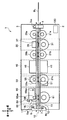
- FIG. 1 It is a figure which shows the whole structure of the paper sheet discrimination
- FIG. It is a figure which shows the arrangement position of the ultraviolet sensor of the lower side of the paper sheet discrimination
- FIG. It is a figure which shows the arrangement position of the ultraviolet sensor of the lower side of the paper sheet discrimination
- FIG. It is a figure which shows the arrangement position of the ultraviolet sensor of the lower side of the paper sheet discrimination
- FIG. It is a figure which shows the arrangement position of the ultraviolet sensor of the upper side of the paper sheet discrimination
- FIG. 1 It is a figure which shows the arrangement position of the ultraviolet sensor of the upper side of the paper sheet discrimination
- FIG. 2 It is a figure which shows the arrangement position of the ultraviolet sensor of the upper side of the paper sheet discrimination
- FIG. It is a figure which shows the arrangement position of both the lower ultraviolet sensor and upper ultraviolet sensor of the paper sheet discrimination
- FIG. It is a figure which shows the arrangement position of both the lower ultraviolet sensor and upper ultraviolet sensor of the paper sheet discrimination
- FIG. It is a figure which shows the arrangement position of both the lower ultraviolet sensor and upper ultraviolet sensor of the paper sheet discrimination
- FIG. It is a figure which shows the arrangement position of both the lower ultraviolet sensor and upper ultraviolet sensor of the paper sheet discrimination
- FIG. 1 It is a figure which shows the structure of the ultraviolet sensor used in Embodiment 1.
- FIG. 2 It is a figure which shows the structure of the ultraviolet sensor used in Embodiment 1.
- FIG. 2 It is a figure which shows the structure of the ultraviolet sensor used in Embodiment 1.
- FIG. 2 It is a figure which shows the mounting structure of the ultraviolet sensor used in Embodiment 1.
- FIG. It is explanatory drawing (1) of the timing of extraction of the ultraviolet-light fluorescence reaction information of the paper sheet discrimination
- FIG. 1 It is a figure (1) which shows the structure of the ultraviolet sensor used with the paper sheet discrimination
- FIG. 1 shows the structure of the ultraviolet sensor of the paper sheet discrimination
- FIG. It is a figure which shows the structure of the ultraviolet sensor of the paper sheet discrimination
- FIG. It is a figure (1) which shows the manufacturing method of the ultraviolet sensor attachment part used in Embodiment 2. It is a figure (1) which shows the manufacturing method of the ultraviolet sensor attachment part used in Embodiment 2. It is a figure (1) which shows the manufacturing method of the ultraviolet sensor attachment part used in Embodiment 2. It is a figure (2) which shows the manufacturing method of the ultraviolet sensor attachment part used in Embodiment 2. It is a figure (2) which shows the manufacturing method of the ultraviolet sensor attachment part used in Embodiment 2. It is a figure (2) which shows the manufacturing method of the ultraviolet sensor attachment part used in Embodiment 2. It is a figure which shows the block configuration of the paper sheet discrimination
- the paper sheet discrimination apparatus 1 is an apparatus that discriminates paper sheets.
- the paper sheet discrimination apparatus 1 is mounted on an automatic teller machine (ATM) and the paper sheet is a banknote.
- ATM automatic teller machine
- paper sheets will be referred to as “banknotes”.
- the ultraviolet sensor fluorescence detection unit
- the paper sheet discrimination device disclosed in Japanese Patent Application Laid-Open No. 2009-157504 is in a state where paper sheets (banknotes) are fluttered when performing discrimination of paper sheets (banknotes) using ultraviolet light (that is, The ultraviolet light fluorescence reaction is detected by the ultraviolet sensor in a state where the position of the paper sheet (banknote) becomes unstable and the position of the paper sheet (banknote) is likely to fluctuate.
- the paper sheet discrimination device disclosed in the Japanese Patent Gazette has a problem that the output of the ultraviolet sensor is likely to fluctuate, and the paper sheet (banknote) using ultraviolet light cannot be accurately identified.
- the paper sheet discrimination apparatus 1 according to the first embodiment also solves such a problem.
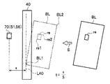
- FIG. 1 is a diagram illustrating an overall configuration of a paper sheet discrimination apparatus according to the first embodiment.
- FIG. 1 for convenience of explanation, the left side plates of the lower frame 2 and the upper frame 3 are omitted, and the internal components are schematically shown.
- the paper sheet discrimination apparatus 1 has a lower frame 2 and an upper frame 3.
- the lower frame 2 and the upper frame 3 are frame members that support each component. Both the lower frame 2 and the upper frame 3 are formed in a rectangular parallelepiped shape.
- a conveyance path 10 for conveying the banknote BL is provided between the lower frame 2 and the upper frame 3.
- the conveyance path 10 is provided so as to extend in a substantially horizontal direction.
- the paper sheet discrimination device 1 Based on the control of the control unit 120, the paper sheet discrimination device 1 performs the discrimination process of the banknotes BL while running the banknotes BL forward or backward along the transport path 10.
- the paper sheet discriminating apparatus 1 is a rotation fulcrum so that the removal of the bill BL when the bill BL is stopped on the transport path 10 and the maintenance of each component around the transport path 10 can be easily performed.
- the upper frame 3 is pivoted about 3ax and the conveyance path 10 can be exposed.
- the lower frame 2 includes a connecting portion 4 connected to the upper frame 3.
- the connecting portion 4 is formed so as to extend upward from a position near the end portion (the front end portion in the illustrated example) of the lower frame 2.
- the connecting portion 4 includes a pivot point 3ax of the upper frame 3 at the upper end.
- the rotation fulcrum 3ax is disposed so as to extend in the left-right direction.
- the connecting portion 4 supports the upper frame 3 so as to be rotatable about the rotation fulcrum 3ax.
- the paper sheet discrimination device 1 has a configuration in which the lower frame 2 and the upper frame 3 are fixed by a lock lever 6.
- the lock lever 6 is supported rotatably about a rotation fulcrum 6ax provided in the vicinity of the end portion (rear end portion in the illustrated example) of the upper frame 3.
- a hook portion 6 b that engages with an engagement portion 7 provided on the lower frame 2 is formed.
- the upper frame 3 is fixed to the lower frame 2 by the hook portion 6b and the engaging portion 7 engaging with each other.
- the paper sheet discrimination device 1 is arranged around the conveyance path 10 with conveyance guides 11 and 16, drive rollers 21a, 21b, and 21c, driven rollers 26a, 26b, and 26c, a magnetic information acquisition unit 30, an optical information acquisition unit 40, and an ultraviolet light.
- a photofluorescence reaction information acquisition unit 50 and a thickness information acquisition unit 60 are provided.
- the conveyance guide 11 is a guide member provided on the lower frame 2.
- the conveyance guide 16 is a guide member provided on the upper frame 3.
- the conveyance guide 11 is referred to as a “lower conveyance guide 11”
- the conveyance guide 16 is referred to as an “upper conveyance guide 16”.
- the lower conveyance guide 11 is an example of a “first guide”.
- the upper transport guide 16 is an example of a “second guide”.
- the magnetic information acquisition unit 30 acquires magnetic information from the banknote BL.
- the optical information acquisition unit 40 acquires linear image information of the banknote BL.
- the ultraviolet light fluorescence reaction information acquisition unit 50 has information on banknotes BL (hereinafter referred to as “ultraviolet light fluorescence reaction”) indicating the presence / absence of an ultraviolet light phosphor region (a region excited by being irradiated with ultraviolet light and emitting excitation light). Information)).
- the thickness information acquisition unit 60 acquires thickness information of the banknote BL.
- a driving roller 21a, 21b, 21c and a reference roller 61 which will be described later, are rotatably attached to the lower conveyance guide 11.
- the rotating shaft bodies of the driving rollers 21a, 21b, 21c and the reference roller 61 are rotatably arranged so as to extend in the left-right direction (that is, the direction perpendicular to the conveyance direction of the bills BL). .
- the distance between the driving roller 21a and the driving roller 21b (distance in the front-rear direction), the distance between the driving roller 21b and the driving roller 21c, and the distance between the driving roller 21c and the reference roller 61 are bill BL
- the distance is set shorter than the length in the short direction.
- the driving rollers 21 a, 21 b, 21 c and the reference roller 61 have a configuration in which a part of each outer peripheral surface is projected into the conveyance path 10 from an opening formed in the lower conveyance guide 11.
- driven rollers 26a, 26b, and 26c are rotatably attached to the upper conveyance guide 16 so as to face the driving rollers 21a, 21b, and 21c.
- the rotating shafts of the driven rollers 26a, 26b, and 26c are disposed so as to be rotatable and vertically movable so as to extend in the left-right direction.
- the driven rollers 26a, 26b, and 26c are pressed against the driving rollers 21a, 21b, and 21c by urging members (compression springs), respectively.
- a support member 68 (described later) of the thickness information acquisition unit 60 is attached to the upper conveyance guide 16.
- the upper transport guide 16 includes a rotation fulcrum 68ax of the support member 68.
- the rotation fulcrum 68ax is arranged extending in the left-right direction.
- the upper transport guide 16 supports the support member 68 so as to be rotatable about the rotation fulcrum 68ax.
- the upper surface 12 of the lower conveyance guide 11 is formed into a flat surface so as to function as the lower conveyance surface of the conveyance path 10.
- the lower surface 17 of the upper conveyance guide 16 is formed in a flat surface shape so as to function as an upper conveyance surface of the conveyance path 10.
- the lower conveyance guide 11 is formed with an opening for projecting a part of the outer peripheral surface of each of the driving rollers 21 a, 21 b, 21 c and a reference roller 61 (described later) of the thickness information acquisition unit 60 into the conveyance path 10. Has been.
- the upper conveyance guide 16 has openings for causing the driven rollers 26 a, 26 b, 26 c and a part of the outer peripheral surface of the detection roller 66 (described later) of the thickness information acquisition unit 60 to protrude into the conveyance path 10. Is formed.
- the driven rollers 26a, 26b, 26c and the detection roller 66 are pressed against the rollers corresponding to the drive rollers 21a, 21b, 21c and the reference roller 61 by an urging member (compression spring).
- the driving rollers 21a, 21b, 21c and the reference roller 61 are rotated by the driving force transmitted from the actuator.
- the driven rollers 26a, 26b, 26c and the detection roller 66 are driven by the rotation of the corresponding rollers while pressing the bill BL against the rollers corresponding to the driving rollers 21a, 21b, 21c and the reference roller 61, respectively. Rotate.
- the paper sheet discrimination apparatus 1 conveys the banknote BL in the front-back direction along the conveyance path 10.
- the driving rollers 21a, 21b, and 21c are rollers that are driven to rotate by an actuator and convey the bills BL.
- the drive rollers 21a, 21b, and 21c are each made of a rubber-based elastic material, and are configured to have a high frictional force against the bill BL.
- the drive roller 21c corresponds to a “conveying member” recited in the claims.
- the driven rollers 26a, 26b, and 26c are rollers that are disposed so as to face the driving rollers 21a, 21b, and 21c, respectively, and sandwich and convey the banknote BL between the driving rollers 21a, 21b, and 21c.
- the driven rollers 26a, 26b, and 26c rotate following the rotation of the driving rollers 21a, 21b, and 21c, respectively.
- the driven rollers 26a, 26b, and 26c are each configured by a metal material, a resin material, a rubber-based elastic material, or a combination of these materials.
- the driven roller 26c is an example of a “clamping member”.
- a magnetic gap roller 31 (to be described later) of the magnetic information acquisition unit 30 is disposed at a position between the drive roller 21a and the drive roller 21b, and (b) an optical information acquisition unit.
- a lower optical image sensor 41 (described later) is disposed between the drive roller 21b and the drive roller 21c, and (c) a lower ultraviolet sensor 51 (described later) of the ultraviolet light fluorescence reaction information acquisition unit 50 is driven.
- the reference roller 61 of the thickness information acquisition unit 60 is disposed at a position downstream (rear side) from the drive roller 21c. .
- the upper frame 3 has (a) a magnetic sensor 36 (to be described later) of the magnetic information acquisition unit 30 disposed at a position between the driven roller 26a and the driven roller 26b, and (b) an optical information acquisition unit. 40, an upper optical image sensor 46, which will be described later, is disposed between the driven roller 26b and the driven roller 26c, and (c) an upper ultraviolet sensor 56, which will be described later, of the ultraviolet light fluorescence reaction information acquisition unit 50 is driven roller 26c. It is assumed that (d) the detection roller 66 of the thickness information acquisition unit 60 is arranged at a position downstream (rear side) from the driven roller 26c. However, the arrangement positions of these members can be changed according to the operation.
- the magnetic information acquisition unit 30 includes a magnetic sensor 36 and a magnetic gap roller 31.
- the magnetic sensor 36 is a sensor that reads magnetic information from the bill BL.
- the magnetic gap roller 31 is a roller that brings the bill BL close to the vicinity of the magnetic sensor reading surface 37 of the magnetic sensor 36.
- the magnetic sensor 36 is attached to the upper frame 3.
- the magnetic gap roller 31 is attached to the lower frame 2 so as to face the magnetic sensor reading surface 37 of the magnetic sensor 36.
- the magnetic sensor 36 has a configuration in which the magnetic sensor reading surface 37 is protruded into the conveyance path 10 from an opening formed in the upper conveyance guide 16.
- the magnetic gap roller 31 has a configuration in which the magnetic gap roller 31 protrudes into the transport path 10 from an opening formed in the lower transport guide 11.
- the magnetic gap roller 31 includes a rotating shaft formed of a nonmagnetic material such as austenitic stainless steel and a cylindrical roller portion formed of a plurality of rubber-based elastic materials.
- the rotating shaft of the magnetic gap roller 31 is arranged so as to be rotatable and vertically movable so as to extend in the left-right direction.
- the magnetic gap roller 31 is rotationally driven by an actuator.
- the magnetic gap roller 31 is pressed upward by a compression spring so as to abut against a limiter provided on the lower frame 2 or the magnetic sensor 36.
- the distance between the outer peripheral surface of the magnetic gap roller 31 and the magnetic sensor reading surface 37 of the magnetic sensor 36 is set to be a value within a predetermined range.
- the optical information acquisition unit 40 includes an optical image sensor 41 disposed on the lower side of the transport path 10 and an optical image sensor 46 disposed on the upper side of the transport path 10.
- the optical image sensors 41 and 46 are constituted by, for example, reflection / transmission type line image sensors.
- the optical image sensor 41 is referred to as a “lower optical image sensor 41”
- the optical image sensor 46 is referred to as an “upper optical image sensor 46”.
- the lower optical image sensor 41 linearly irradiates predetermined irradiation light in the upward direction, and linearly receives diffuse reflection light in which a part of the irradiation light is diffused on the lower surface of the banknote BL.
- the diffusely reflected light received linearly represents a linear image (reflected image) of light diffused on the lower surface of the banknote BL.
- the lower optical image sensor 41 linearly receives transmitted light in which part of the irradiation light irradiated linearly from the upper optical image sensor 46 has passed through the bill BL.
- the transmitted light received linearly represents a linear image (transmitted image) of light transmitted from the upper surface to the lower surface of the bill BL.
- the upper optical image sensor 46 linearly irradiates predetermined irradiation light downward, and linearly receives diffuse reflection light in which a part of the irradiation light is diffused on the upper surface of the banknote BL.
- the diffusely reflected light received linearly represents a linear image (reflected image) of light reflected on the upper surface of the banknote BL.
- the upper optical image sensor 46 linearly receives the transmitted light in which part of the irradiation light irradiated linearly from the lower optical image sensor 41 passes through the banknote BL.
- the transmitted light received linearly represents a linear image (transmitted image) of light transmitted from the lower surface of the banknote BL to the upper surface.
- the optical information acquisition unit 40 receives the diffusely reflected light and the transmitted light by the optical image sensors 41 and 46, thereby representing information indicating the reflected image of the banknote BL (hereinafter referred to as “reflected image information”) and Information representing a transmission image (hereinafter referred to as “transmission image information”) is acquired.
- the control unit 120 (see FIG. 1) of the paper sheet discrimination device 1 continuously acquires the reflected image information and the transmitted image information from the optical information acquisition unit 40, and synthesizes the linear images represented by these image information. By this, the image information of the whole banknote BL is acquired.
- the ultraviolet light fluorescence reaction information acquisition unit 50 includes a plurality of ultraviolet sensors. Here, it is assumed that the ultraviolet light fluorescence reaction information acquisition unit 50 includes two ultraviolet sensors 51 and 56. However, the ultraviolet light fluorescence reaction information acquisition unit 50 may have three or more ultraviolet sensors.
- the ultraviolet sensor 51 is a sensor disposed below the conveyance path 10.
- the ultraviolet sensor 56 is a sensor arranged on the upper side of the conveyance path 10.
- the ultraviolet sensor 51 is referred to as a “lower ultraviolet sensor 51” and the ultraviolet sensor 56 is referred to as an “upper ultraviolet sensor 56”.
- the lower ultraviolet sensor 51 is an example of a “first ultraviolet sensor”.
- the upper ultraviolet sensor 56 is an example of a “second ultraviolet sensor”.
- the ultraviolet sensors 51 and 56 irradiate the bill BL with ultraviolet light emitted by the light emitting unit 71 (see FIG. 5A), and a specific part of the surface of the bill BL (ultraviolet phosphor region described later). Excitation light emitted from the phosphor when the phosphor contained in a paper sheet such as copy paper (quality paper) is excited by ultraviolet light and excited by re (see FIG. 7)) ) Is received by the light receiving unit 72 (see FIG. 5A). Thereby, the ultraviolet light fluorescence reaction characteristic of the banknote BL is detected.
- the arrangement position and configuration of the ultraviolet sensors 51 and 56 will be described later.
- the thickness information acquisition unit 60 includes a reference roller 61, a detection roller 66, a support member 68, and a displacement detection sensor 69.
- the reference roller 61 is a roller disposed at a predetermined position in order to detect the thickness of the bill BL.
- the detection roller 66 is a roller that sandwiches the bill BL with the reference roller 61.
- the support member 68 is a member that supports the detection roller 66 so as to be movable in the vertical direction.
- the displacement detection sensor 69 is a sensor that detects the thickness of the bill BL by detecting the displacement amount (movement amount) of the detection roller 66.
- the reference roller 61 is arranged in a direction orthogonal to the conveyance direction of the bills BL.
- the reference roller 61 is made of a predetermined metal material so as not to be easily deformed.
- the reference roller 61 is rotationally driven by an actuator.
- the detection roller 66 is disposed to face the reference roller 61.
- the detection roller 66 is made of a metal material in order to generate an eddy current by a high-frequency magnetic field generated by the displacement detection sensor 69.
- the detection roller 66 rotates following the rotation of the reference roller 61.
- the detection roller 66 is pressed against the reference roller 61 by an urging member (compression spring).
- the detection roller 66 is pushed by the bill BL and is displaced (moved) upward by the thickness of the bill BL.
- the support member 68 is attached to the upper transport guide 16 so as to be rotatable about a rotation fulcrum 68ax.
- the rotation fulcrum 68ax is arranged extending in the left-right direction.
- the support member 68 rotatably supports the detection roller 66 about the rotation shaft 66ax.
- the support member 68 moves about the axis of the rotation fulcrum 68ax to move the detection roller 66 in the vertical direction with respect to the conveyance path 10.
- the displacement detection sensor 69 is an eddy current sensor disposed above the detection roller 66.
- the displacement detection sensor 69 uses the position of the detection roller 66 when the detection roller 66 is in contact with the reference roller 61 as a reference position, and detects the relative displacement (movement amount) of the detection roller 66 from the reference position. .
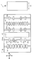
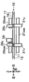
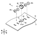
- FIGS. 2A to 4C are diagrams showing the arrangement position of the lower ultraviolet sensor 51.
- FIG. 2A to 2C show the arrangement positions of the lower ultraviolet sensor 51 viewed from the upper side, the left side, and the front side, respectively.
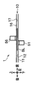
- 3A to 3C are diagrams showing the arrangement positions of the upper ultraviolet sensor 56.
- FIG. 3A to 3C schematically show the arrangement positions of the upper ultraviolet sensor 56 viewed from the upper side, the left side, and the front side, respectively.
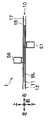
- 4A to 4C are diagrams showing the arrangement positions of both the lower ultraviolet sensor 51 and the upper ultraviolet sensor 56.
- FIG. 4A to 4C schematically show the arrangement positions of both the lower ultraviolet sensor 51 and the upper ultraviolet sensor 56 viewed from the upper side, the left side, and the front side, respectively.
- the number of drive rollers 21c is not limited to four and can be increased or decreased.
- the length of the rotating shaft 21cax is substantially the same as the lateral width (the width in the left-right direction) of the lower conveyance guide 11.
- the rotation shaft 21cax is disposed so as to extend over substantially the entire lateral width of the lower conveyance guide 11.
- the bill BL is conveyed in the direction of arrow A1 by the drive roller 21c.
- the lower ultraviolet sensor 51 is disposed in the vicinity of the rotation shaft 21cax of the drive roller 21c and at a position shifted downstream (rear side) from the position of the rotation shaft 21cax.
- the lower ultraviolet sensor 51 can be arranged at a position shifted from the arrangement position of the rotation shaft 21cax to the upstream side (front side).
- the number of driven rollers 26c is not limited to four and can be increased or decreased.
- the total length of the two rotating shafts 26cax of the driven roller 26c is shorter than the length of one rotating shaft 21cax of the drive roller 21c.
- the two rotation shafts 26cax are arranged separately in the left-right direction so as to extend only in a partial region with respect to the lateral width of the upper conveyance guide 16.
- the upper ultraviolet sensor 56 is disposed between the two rotation shafts 26cax.
- the upper ultraviolet sensor 56 is disposed in the vicinity of the rotation shaft 26cax of the driven roller 26c and at a position shifted in the axial direction from the position of the rotation shaft 26cax. In the first embodiment, the upper ultraviolet sensor 56 is disposed at a position directly beside the rotation shaft 26cax.
- the lower ultraviolet sensor 51 and the upper ultraviolet sensor 56 are arranged so as to be shifted from each other in the front-rear direction (the conveyance direction of the bills BL). Further, the lower ultraviolet sensor 51 and the upper ultraviolet sensor 56 are arranged so as to be shifted from each other in the left-right direction (the direction orthogonal to the bill BL conveyance direction). Therefore, the lower ultraviolet sensor 51 and the upper ultraviolet sensor 56 are disposed at positions that do not face each other.
- At least one of the lower ultraviolet sensor 51 and the upper ultraviolet sensor 56 is disposed at a position where the ultraviolet phosphor region re provided on the banknote BL can be irradiated with ultraviolet light.
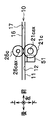
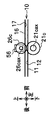
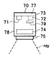
- FIGS. 5 and 6 are diagrams showing the configuration of the ultraviolet sensor 70 (51, 56) used in the first embodiment.
- 5A to 5C schematically show the configuration of the ultraviolet sensor 70 viewed from the front side, the left side, and the lower side, respectively.
- FIG. 6 is a diagram showing a mounting configuration of the ultraviolet sensor 70.
- the ultraviolet sensor 70 includes a light emitting unit 71, a light receiving unit 72, an ultraviolet light shielding body 79, a case 73, a rod lens 74, and an element mounting substrate 77.
- the light emitting unit 71 emits ultraviolet light.
- the light receiving unit 72 receives light.
- the ultraviolet light shield 79 transmits visible light and shields ultraviolet light.
- the case 73 houses the light emitting unit 71, the light receiving unit 72, the ultraviolet light shield 79, the rod lens 74, and the element mounting substrate 77.
- the rod lens 74 irradiates ultraviolet light in one direction, and is excited by the ultraviolet light reflected by the banknote BL or the phosphor contained in the banknote BL, and collects the excitation light emitted from the phosphor.
- the paper sheet discrimination apparatus 1 conveys the banknote BL so that the banknote BL passes through the irradiation direction of the rod lens 74.
- the element mounting substrate 77 is a substrate on which the light emitting unit 71 and the light receiving unit 72 are mounted.
- the case 73 includes an optical path 75 and a storage portion 78.
- the light path 75 is a transparent part that allows light to pass through.
- the housing part 78 is a part for housing the light part 71, the light receiving part 72, the ultraviolet light shield 79, the rod lens 74, and the element mounting board 77.
- the ultraviolet sensor 70 uses the rod lens 74 to spread the ultraviolet light ray emitted from the light emitting unit 71 in the left-right direction and linearly irradiate the surface of the banknote BL.
- the ultraviolet sensor 70 is excited by the diffusely reflected light by the irradiated ultraviolet ray and the phosphor included in the banknote BL, and condenses the excitation light emitted from the phosphor in one direction to the ultraviolet light shield 79. By blocking the reflected light, only the excitation light is received and detected by the light receiving unit 72.
- the light path 75 is formed in a cylindrical shape (see FIG. 5C).
- the accommodating part 78 is formed in the rectangular parallelepiped shape (refer FIG. 5B).
- the ultraviolet sensor 70 is mounted on the ultraviolet sensor mounting substrate 115.
- An amplifying unit 111 that amplifies a signal output from the ultraviolet sensor 70 is mounted on the ultraviolet sensor mounting substrate 115.
- the ultraviolet sensor 70 is a surface opposite to the lower surface (upper conveying surface) 17 of the upper conveying guide 16 and the upper surface (lower conveying surface) 12 of the lower conveying guide 11 (the surface not facing the conveying path 10). ) In the space partitioned by the partition portion 18 provided.
- a dust-proof member 116 such as a sponge is disposed between the ultraviolet sensor mounting substrate 115 on which the ultraviolet sensor 70 is mounted and the partition portion 18 of the conveyance guide 16 formed on the surface opposite to the conveyance surface 17.
- a light transmissive cover member 76 is disposed between the light path 75 of the ultraviolet sensor 70 and the transport path 10. Thereby, the ultraviolet sensor 70 prevents dust from entering the inside or adhering to the surface of the light path 75.
- FIG. 7 and FIG. 8 are explanatory diagrams of the timing of cutting out the ultraviolet light fluorescence reaction information of the paper sheet discrimination apparatus 1 according to the first embodiment.
- the paper sheet discrimination device 1 When discriminating a bill BL, the paper sheet discrimination device 1 acquires the magnetic information of the bill BL with the magnetic information acquisition unit 30 (see FIG. 1) while conveying the bill BL, and the image information acquisition unit 40 acquires the bill.
- the image information of the lower surface and the upper surface of the BL is acquired
- the ultraviolet light fluorescence reaction information acquisition unit 50 acquires the ultraviolet light fluorescence reaction information of the lower surface and the upper surface of the bill BL
- the thickness information acquisition unit 60 ( 1), the thickness information of the bill BL is acquired.
- the paper sheet discrimination apparatus 1 will be described on the assumption that the bill BL is being transported at the transport speed “S”. Further, description will be made assuming that the distance from the reading line L40 of the optical image sensor 41 (or 46) of the image information acquisition unit 40 to the ultraviolet sensor 70 of the ultraviolet light fluorescence reaction information acquisition unit 50 is “x”.
- the paper sheet discrimination device 1 stores various information of the acquired banknote BL in the storage unit. At this time, the paper sheet discrimination apparatus 1 continuously acquires the ultraviolet light fluorescence reaction information on the lower surface and the upper surface of the banknote BL at regular intervals by the ultraviolet sensor 70, and the obtained ultraviolet light fluorescence reaction information. Is stored in the storage unit. Here, description will be made assuming that the paper sheet discrimination device 1 acquires the information shown in FIG. 8 as the ultraviolet light fluorescence reaction information of the banknote BL and stores the acquired information in the storage unit.
- the vertical axis represents the output value of the ultraviolet sensor 70
- the horizontal axis represents time.
- the output value of the ultraviolet sensor 70 represents the intensity of the ultraviolet light fluorescence reaction in the ultraviolet light phosphor region re of the banknote BL (that is, the ultraviolet light fluorescence reaction characteristic of the banknote BL).
- the area Ore shown in FIG. 8 is an area where the ultraviolet light fluorescence reaction characteristic is detected from the banknote BL.
- Time t1 is the time when the leading edge BL1 (see FIG. 7) of the banknote BL reaches the ultraviolet sensor 70.
- Time t2 is the time when the tip end re1 (see FIG. 7) of the ultraviolet phosphor region re of the banknote BL reaches the ultraviolet sensor 70.
- Time t3 is the time when the rear end portion re2 (see FIG. 7) of the ultraviolet light phosphor region re of the bill BL has passed through the ultraviolet sensor 70.
- Time t4 is the time when the rear end BL2 (see FIG. 7) of the bill BL passes the ultraviolet sensor 70.
- the time c1 is a time that is an arbitrary time before the time t2.
- the time c2 is a time that is an arbitrary time before the time t3.
- the time t1 is a time that is a time “t” after the time when the leading edge BL1 (see FIG. 7) of the bill BL passes the reading line L40 of the image information acquisition unit 40.
- the time t2 is a time that is a time “t” after the time when the tip portion re1 (see FIG. 7) of the ultraviolet phosphor region re of the bill BL passes the reading line L40 of the image information acquisition unit 40.
- the time t3 is a time that is a time “t” after the time when the rear end portion re2 (see FIG. 7) of the ultraviolet phosphor region re of the banknote BL passes the reading line L40 of the image information acquisition unit 40.
- the time t4 is a time that is a time “t” after the time when the rear end portion BL2 (see FIG. 7) of the bill BL passes the reading line L40 of the image information acquisition unit 40.
- the value of the time “t” is a value calculated by dividing the value “x” of the distance from the reading line L40 of the image information acquisition unit 40 to the ultraviolet sensor 70 by the value “S” of the conveyance speed of the bill BL. .
- the control unit 120 (see FIG. 1) of the paper sheet discrimination device 1 is based on the image information of the bill BL acquired by the image information acquisition unit 40, and the tip of the bill BL and the tip of the ultraviolet phosphor region re.
- the time at which the part re1, the rear end part re2 of the ultraviolet phosphor region re, and the rear end part BL2 of the bill BL have reached the reading line L40 of the image information acquisition unit 40 (or the reading line L40) Can be recognized).
- control unit 120 cuts out information at times c1 to c2 from the ultraviolet light fluorescence reaction information as ultraviolet light fluorescence reaction information (hereinafter referred to as “discrimination area information”) of the area used for discrimination. .
- the control unit 120 specifies the ultraviolet light fluorescence reaction information on the lower surface and the upper surface of the banknote BL based on the information of the discrimination area.
- the ultraviolet light fluorescence reaction information on the lower surface of the banknote BL will be described as “VA (n)”
- the ultraviolet light fluorescence reaction information on the upper surface of the banknote BL will be described as “VB (n)”.
- the ultraviolet light fluorescence reaction information VA (n) is the ultraviolet light fluorescence reaction information of the bill BL detected by the lower ultraviolet sensor 51 (the relationship between the intensity ratio of the ultraviolet light fluorescence reaction on the lower surface of the bill BL and the transport distance). Information).
- the ultraviolet light fluorescence reaction information VB (n) is the ultraviolet light fluorescence reaction information of the bill BL detected by the upper ultraviolet sensor 56 (the relationship between the intensity ratio of the ultraviolet light fluorescence reaction on the upper surface of the bill BL and the transport distance). Information).
- control unit 120 determines the money of the bill BL. Identify the species.
- control unit 120 reads registered ultraviolet light fluorescence reaction information corresponding to the specified denomination from the storage unit, and the ultraviolet light fluorescence reaction information VA (n), VB (n) is read from the storage unit. It is determined whether or not the registered ultraviolet light fluorescence reaction information is applicable.
- control unit 120 can accurately determine the authenticity of the bill BL using the ultraviolet light by detecting the ultraviolet light fluorescence reaction characteristics of the lower surface and the upper surface of the bill BL.
- control part 120 uses the various information acquired by the magnetic sensor 36, the optical image sensors 41 and 46, the ultraviolet sensors 51 and 56, and the displacement detection sensor 69 comprehensively, the number of the banknotes BL, a driving
- the lower ultraviolet sensor 51 and the upper ultraviolet sensor 56 are arranged at positions shifted from each other. Therefore, the lower ultraviolet sensor 51 can suppress receiving the excitation light that is excited by the transmitted light that has passed through the banknote BL, with a part of the ultraviolet light emitted from the upper ultraviolet sensor 56.
- the lower ultraviolet sensor 51 can receive only the excitation light excited by the ultraviolet light emitted from the lower ultraviolet sensor 51 itself.
- the upper ultraviolet sensor 56 can receive only excitation light excited by the ultraviolet light emitted from the upper ultraviolet sensor 56 itself.
- Such a paper sheet discrimination device 1 can suppress the ultraviolet sensors 51 and 56 from interfering with each other. Moreover, the paper sheet discrimination apparatus 1 is a counterfeit in which the bill BL to be identified has the ultraviolet light phosphor region re in the entire portion of the paper surface in the discrimination using the ultraviolet light, and the ultraviolet light fluorescence reaction is performed on the bill BL. Even if it is detected from all the parts of the paper, it is possible to appropriately discriminate the banknote BL as a fake note by determining whether or not the ultraviolet light fluorescence reaction has been detected from only a specific part of the paper. it can.
- the paper sheet discrimination apparatus 1 arranges the ultraviolet sensor 51 at a position as close as possible to the rotation shaft 21cax of the driving roller 21a, and also places the ultraviolet sensor 56 in the rotation shaft of the driven roller 26a. It is arranged right next to 26cax. Therefore, the ultraviolet sensors 51 and 56 are disposed in the vicinity of the position where the bill BL is clamped, and the ultraviolet light fluorescence reaction characteristic of the bill BL can be detected at the position. Thereby, the paper sheet discrimination apparatus 1 can detect the ultraviolet light fluorescence reaction characteristic of the banknote BL in a state in which the influence of the output fluctuation due to the fluttering of the banknote BL is suppressed to almost zero. UV light fluorescence reaction characteristics can be detected. Therefore, the paper sheet discrimination apparatus 1 can perform authentication with high accuracy.
- the ultraviolet light fluorescence reaction characteristics of the lower surface and the upper surface of the banknote BL are measured by the ultraviolet sensors 51 and 56 arranged so as not to face each other. By detecting, it is possible to distinguish between the partial ultraviolet light fluorescence reaction characteristic of the banknote BL and the ultraviolet light fluorescence reaction characteristic of the entire surface of the copy paper or the like. Therefore, the paper sheet discrimination apparatus 1 can improve the authenticity discrimination performance (determination performance between genuine bills and counterfeits) of the bills BL in discrimination using ultraviolet light.
- the paper sheet discrimination apparatus 1 since the ultraviolet sensors 51 and 56 are arranged in the vicinity of the rotation shaft 21cax of the driving roller 21, the influence of output fluctuation due to the flickering of the conveyance of the banknote BL is almost zero. It is possible to detect the ultraviolet light fluorescence reaction characteristic of the banknote BL in a state in which it is suppressed. Therefore, the paper sheet discrimination apparatus 1 can perform authentication with high accuracy.
- the paper sheet discrimination apparatus 1 In the paper sheet discrimination apparatus 1 (see FIG. 6) according to the first embodiment, the case 73 of the ultraviolet sensor 70 (51, 56) is exposed to the outside. Therefore, in order to obtain a dustproof effect, the paper sheet discrimination apparatus 1 is provided with a dustproof member 116 between the ultraviolet sensor mounting substrate 115 and the partition portion 18 of the transport guide 16 formed on the surface opposite to the transport surface 17. Is installed. However, in this case, in the paper sheet discrimination apparatus 1, the cost and labor for installing the dust-proof member 116 are required, so that the manufacturing cost may increase.
- a paper sheet discrimination apparatus 1B that can obtain a dustproof effect with an inexpensive configuration is provided.
- the paper sheet discrimination apparatus 1B is configured as a capsule-type ultraviolet sensor 80 covered with an outer case 81, and is conveyed.
- the capsule-type ultraviolet sensor 80 and the driven roller 26c are mounted on the conveyance guide 16 (the conveyance guide 11 is the same) via the ultraviolet sensor mounting portion 91 provided on the guide 17.
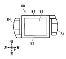
- FIGS. 9A to 10 are diagrams showing configurations of the capsule-type ultraviolet sensor 80 and the ultraviolet sensor mounting portion 91 used in the paper sheet discrimination apparatus 1B according to the second embodiment.
- FIG. 9A shows the configuration of the capsule-type ultraviolet sensor 80 and the ultraviolet sensor mounting portion 91 as viewed obliquely from above.
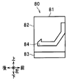
- FIG. 9B shows the configuration of the ultraviolet sensor mounting portion 91 as viewed from above.
- FIG. 10 shows a cross-sectional configuration of the capsule-type ultraviolet sensor 80 and the ultraviolet sensor mounting portion 91 as viewed from the front.
- FIG. 11 is a diagram showing a configuration of the capsule ultraviolet sensor 80 used in the second embodiment.
- 11A to 11D show the configuration of the capsule-type ultraviolet sensor 80 as viewed obliquely from above, from above, from below, and from the left.
- 12A to 13C are diagrams showing a method for manufacturing the ultraviolet sensor mounting portion 91 used in the second embodiment.
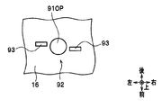
- the paper sheet discrimination apparatus 1B has a configuration in which an ultraviolet sensor mounting portion 91 is provided in the transport guide 16.
- the ultraviolet sensor mounting portion 91 is a part where the capsule ultraviolet sensor 80 and the driven roller 26c are mounted.
- the transport guide 11 (see FIG. 1) also has the same configuration as the transport guide 16.
- the ultraviolet sensor mounting portion 91 is arranged at a position shifted in the axial direction from the arrangement position of the driven roller 26c.
- the ultraviolet sensor mounting portion 91 is provided with an ultraviolet sensor storage portion 92, and a capsule type ultraviolet sensor 80 is stored in the ultraviolet sensor storage portion 92.
- a circular hole-shaped opening 91OP is formed through the bottom of the ultraviolet sensor housing 92.
- the opening 91OP functions as an insertion hole into which a lens window 83 (see FIG. 11A), which will be described later, is inserted.
- two engagement portions 93 are formed in the ultraviolet sensor storage portion 92.
- the engaging portion 93 is a portion that engages with a protrusion 84 (see FIGS. 10 to 11C), which will be described later, of the capsule ultraviolet sensor 80.
- the engaging portion 93 is formed to be bent in a bowl shape.
- the engaging portion 93 constitutes a fixing mechanism of the capsule type ultraviolet sensor 80 together with a later-described protrusion 84 (see FIGS. 10 to 11C) of the capsule type ultraviolet sensor 80.
- the two engaging portions 93 are formed to face each other through the opening 91OP.
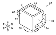
- the capsule-type ultraviolet sensor 80 used in the second embodiment has a capsule-type configuration in which the ultraviolet sensor 70 is covered with an outer case 81 and a dustproof packing 89. Thereby, the capsule-type ultraviolet sensor 80 prevents dust (paper powder, dust, etc.) from adhering to the case 73 (particularly, the light path 75) of the ultraviolet sensor 70.
- the case 73 is referred to as an “inner case 73” when distinguished from the outer case 81.
- the outer case 81 includes a storage portion 82 (see FIGS. 11A to 11D), a lens window portion 83 (see FIGS. 11A and 11B), and two protrusions 84 (see FIGS. 11A to 11D). Yes.
- the storage part 82 is a part for storing the ultraviolet sensor 70.
- the storage portion 82 is formed in a rectangular parallelepiped shape.
- the lens window 83 is a part that transmits light (transmission part).
- the lens window 83 is formed in a columnar shape (or a cylindrical shape).
- the protrusion 84 is a part that engages with the engaging part 93 formed in the ultraviolet sensor mounting part 91.
- the protrusion 84 is formed so as to protrude from the storage portion 82 in the outer peripheral direction (radial direction) of the lens window portion 83.
- the capsule-type ultraviolet sensor 80 has a portion 86 (hereinafter, referred to as “first positioning portion”) that defines an arrangement position of the ultraviolet sensor 70 inside the capsule-type ultraviolet sensor 80.
- the first positioning portion 86 is formed in a flat surface shape.
- the first positioning portion 86 is in contact with the orthogonal surface 73a formed on the inner case 73 of the ultraviolet sensor 70, so that the distance from the element mounting substrate 77 to the lens 74 becomes a predetermined distance “H1”. 70 positions are defined.
- the orthogonal surface 73 a is a flat surface that is orthogonal to the irradiation direction of the ultraviolet light of the inner case 73 around the light path 75.
- the capsule ultraviolet sensor 80 has a portion 87 (hereinafter referred to as “second positioning portion”) that defines an arrangement position of the capsule ultraviolet sensor 80 with respect to the ultraviolet sensor mounting portion 91 formed outside.
- the second positioning portion 87 is formed in a flat surface shape.
- the second positioning portion 87 is in contact with the flat surface 95 of the ultraviolet sensor mounting portion 91 formed on the opposite side to the conveyance surface 96, so that the distance from the lens 74 to the surface of the bill BL is a predetermined distance “H2”.
- the arrangement position of the capsule ultraviolet sensor 80 is defined.
- the lens window 83 is formed in a columnar shape (or cylindrical shape), and an opening 91OP formed in the ultraviolet sensor mounting portion 91 (see FIGS. 9B and 10). It is inserted in.
- the lens window 83 is formed to have substantially the same size as the opening 91OP. Therefore, the lens window 83 functions as a sealing cover that seals the opening 91OP and prevents dust from entering the ultraviolet sensor housing 92.
- the capsule ultraviolet sensor 80 is rotated along the inner wall surface of the opening 91OP formed in a circular hole shape with the lens window 83 fitted in the opening 91OP. At this time, the protruding portion 84 and the engaging portion 93 are engaged. Thereby, the capsule-type ultraviolet sensor 80 is fixed to the ultraviolet sensor mounting portion 91.
- the paper sheet discrimination device 1B sends ultraviolet light from the light-emitting unit 71 (see FIG. 10) of the capsule-type ultraviolet sensor 80 while conveying the banknote BL forward or backward when discriminating the banknote BL.
- Capsule-type ultraviolet rays are reflected toward the BL, and the reflected light reflected by the surface of the bill BL is reflected by the ultraviolet light irradiated on the bill BL and the excitation light emitted from the ultraviolet phosphor region when the ultraviolet light is irradiated.
- the light is condensed in one direction by the lens 74 of the sensor 80, the reflected light is shielded by the ultraviolet light shield 79, and only the excitation light is received by the light receiving unit 72 (see FIG. 10), and the output value of the fluorescence reaction is read.
- the bills BL pass through the arrangement position of the capsule type ultraviolet sensor 80 while fluttering along the conveyance path 10 (see FIG. 1). Therefore, a state in which dust (paper powder, dust, etc.) flies in the conveyance path 10 occurs.
- the capsule-type ultraviolet sensor 80 prevents the dust from entering the capsule-type ultraviolet sensor 80 by the outer case 81 and the dustproof packing 89. Thereby, the capsule-type ultraviolet sensor 80 prevents dust from adhering to the inner case 73 (particularly, the light path 75) of the ultraviolet sensor 70.
- the edge portion of the banknote BL does not enter the opening 91OP of the ultraviolet sensor mounting portion 91, thereby preventing the banknote BL from being jammed (conveyance failure).
- the opening 91OP is closed by a lens window 83 formed in a columnar shape (or a cylindrical shape).
- the paper sheet discrimination device 1B may not need to be equipped with the capsule-type ultraviolet sensor 80 depending on the specifications. Therefore, it is preferable that the paper sheet discrimination apparatus 1B can be selectively changed between a configuration in which the capsule ultraviolet sensor 80 is mounted and a configuration in which the capsule ultraviolet sensor 80 is not mounted.
- the conveyance guide 16 provided with the ultraviolet sensor mounting portion 91a (see FIGS. 12B and 12C) in which the opening 91OP is formed, and the ultraviolet sensor mounting portion 91b (see FIG. 12) in which the opening 91OP is not formed. 13B and FIG. 13C) can be realized by selectively using the conveyance guide 16 provided.
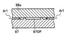
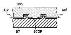
- the ultraviolet sensor mounting portions 91a and 91b are formed as molds with a piece structure by using molds 98a and 98b in which a part can be exchanged and a part of the mold is exchanged. By making the hole 97OP closed or opened, it can be selectively manufactured.
- FIG. 12A shows that the ultraviolet sensor mounting portion 91a is manufactured by placing the mold 98a on the mold 97 and pouring the molten resin between the mold 98a and the mold 97. ing.
- the mold 98a is a replaceable mold.
- the mold 98a is configured to close the hole 97OP.
- the mold 98a is configured to inhibit the molten resin flow Ar1 so that the resin does not flow into the hole 97OP.
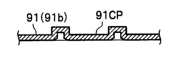
- FIG. 12B and 12C show the configuration of the ultraviolet sensor mounting portion 91a manufactured by the manufacturing method shown in FIG. 12A.
- An opening 91OP is formed in the ultraviolet sensor mounting portion 91a.
- the mold 98b is placed on the mold 97, and the melted resin is poured between the mold 98b and the mold 97 to manufacture the ultraviolet sensor mounting portion 91b. Is shown.
- the mold 98b is a replaceable mold.
- the mold 98b is configured to open the hole 97OP.
- the mold 98b has a configuration that does not inhibit the molten resin flow Ar2 so that the resin flows into the holes 97OP.
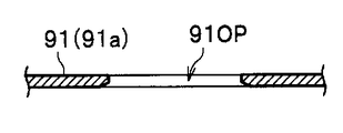
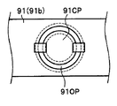
- FIG. 13B and 13C show the configuration of the ultraviolet sensor mounting portion 91b manufactured by the manufacturing method shown in FIG. 13A.
- the ultraviolet sensor mounting portion 91b is formed with a lid portion 91CP. Therefore, the ultraviolet sensor mounting portion 91 has a configuration in which the opening portion 91OP is blocked by the lid portion 91CP and the opening portion 91OP is not exposed to the transport path 10 (see FIG. 1).
- the lid portion 91CP is formed in a circular shape with an inclined surface at the edge portion so that the edge portion of the bill BL does not enter the opening portion 91OP of the ultraviolet sensor mounting portion 91. .
- the paper sheet discrimination apparatus 1B is manufactured by replacing a part of the mold with the mold 98a or the mold 98b in the manufacturing process of the ultraviolet sensor mounting portion 91, thereby forming the opening 91OP.
- the ultraviolet sensor attachment part 91a and the ultraviolet sensor attachment part 91b in which the opening 91OP is not formed can be selectively manufactured.
- the paper sheet discrimination apparatus 1B mounts the capsule ultraviolet sensor 80 by selectively using the conveyance guide 16 provided with the ultraviolet sensor attachment portion 91a and the conveyance guide 16 provided with the ultraviolet sensor attachment portion 91b.
- the configuration and the configuration in which the capsule ultraviolet sensor 80 is not mounted can be selectively changed.
- Such a paper sheet discrimination apparatus 1B prevents the opening 91OP from being exposed to the transport path 10 (see FIG. 1) when the capsule ultraviolet sensor 80 does not need to be mounted. Can do. Thereby, since the paper sheet discrimination apparatus 1B can suppress generation
- the authenticity discrimination performance (genuine bill) of the banknote BL in the discrimination using ultraviolet light. Can be improved. Further, according to the paper sheet discrimination apparatus 1B, as with the paper sheet discrimination apparatus 1, it is possible to perform authentication with high accuracy.
- the ultraviolet sensor 70 is configured as a capsule-type ultraviolet sensor 80 covered with an outer case 81.
- a dustproof effect can be obtained with an inexpensive configuration.
- the conveyance performance of the bills BL can be improved by providing the cylindrical lens window 83 in the outer case 81.
- the ultraviolet sensor 70 (51, 56) when manufacturing the ultraviolet sensor mounting portion 91, a part of the mold is configured as a replaceable mold 98a or 98b of the frame structure.
- the opening 91OP can be arbitrarily closed. Therefore, according to the paper sheet discrimination apparatus 1B, the ultraviolet sensor 70 (51, 56) is selectively mounted or not mounted, or there are a plurality of positions where the ultraviolet sensor 70 (51, 56) is mounted.
- the conveyance guide 16 provided with the ultraviolet sensor mounting portion 91 can be formed in various shapes at low cost in accordance with the mounting state of the ultraviolet sensor 70 (51, 56).
- the driving timing (acquisition timing of the ultraviolet light fluorescence reaction characteristic) of the ultraviolet sensor 70 (51, 56) of the ultraviolet light fluorescence reaction information acquisition unit 50 is set to the optical image sensor 41, 46 of the optical information acquisition unit 40.
- a paper sheet discrimination device 1C that is synchronized with the drive timing of the light emitting unit (image information acquisition timing).
- FIG. 14 is a diagram illustrating a block configuration of a paper sheet discrimination apparatus 1C according to the third embodiment.
- the above-described control unit 120 will be described as a “main control unit 120”.
- the paper sheet discrimination apparatus 1C has a configuration that satisfies the following items (1) to (4).
- the paper sheet discrimination apparatus 1C includes two drive control units 110 for driving the optical image sensor.
- the drive control unit 110 includes an amplification unit 111 that amplifies a signal output from the ultraviolet sensor 70.
- a contact image sensor (CIS) 49 constituting the lower optical image sensor 41 and one drive control unit 110 are connected by a connection cord 130, and an upper optical image sensor 46 and the other drive control unit 110 are connected by a connection cord 130.
- the ultraviolet sensor 70 constituting the lower ultraviolet sensor 51 and one drive control unit 110 are connected by the connection cord 130, and the ultraviolet sensor constituting the upper ultraviolet sensor 56 70 and the other drive control unit 110 are connected by a connection cord 130.
- the paper sheet discrimination apparatus 1C has a configuration in which two drive control units 110 and a main control unit 120 are connected by a connection cord 130.
- the paper sheet discrimination apparatus 1C operates as follows when discriminating the bills BL.
- the paper sheet discrimination device 1C acquires the magnetic information of the bill BL with the magnetic information acquisition unit 30 (see FIG. 1) while conveying the bill BL, and acquires the optical information of the image information acquisition unit.
- the image information of the lower surface and upper surface of the bill BL is acquired by the unit 40
- the ultraviolet light fluorescence reaction information of the lower surface and upper surface of the bill BL is acquired by the ultraviolet light fluorescence reaction information acquisition unit 50
- the thickness information The thickness information of the banknote BL is acquired by the acquisition unit 60 (see FIG. 1).
- the ultraviolet sensor 70 of the paper sheet discrimination device 1C irradiates the bill BL with ultraviolet light from the light emitting unit 71, and receives the excitation light from the surface of the bill BL with the light receiving unit 72, and the received excitation light.
- An analog signal having a value corresponding to the intensity of the signal is output to the drive controller 110.
- the amplifying unit 111 of the drive control unit 110 When an analog signal is input from the ultraviolet sensor 70, the amplifying unit 111 of the drive control unit 110 amplifies the input signal and converts it to an analog signal or AD-converts it into digital data, and sends it to the main control unit 120. Output.
- the main control unit 120 comprehensively uses various types of information acquired by the magnetic sensor 36, the optical image sensors 41 and 46, the ultraviolet sensors 70 (51 and 56), and the displacement detection sensor 69, thereby enabling the number of bills BL and , Distinguish the running state, denomination, authenticity, degree of damage (loss).
- Such a paper sheet discrimination apparatus 1C is temporarily compared with the paper sheet discrimination apparatus 1001 according to the comparative example when compared with the paper sheet discrimination apparatus 1001 according to the comparative example configured as follows. The following effects can be obtained.
- the paper sheet discrimination apparatus 1001 has a configuration that satisfies the following items (1) to (4).
- the paper sheet discrimination apparatus 1001 includes two drive control units 110 for driving an optical image sensor and two drive control units 1110 for driving an ultraviolet sensor.
- the drive control unit 1110 for driving the ultraviolet sensor includes an amplification unit 111 that amplifies the signal output from the ultraviolet sensor 70.
- the drive control unit 110 for driving the optical image sensor may have a configuration in which the amplification unit 111 is deleted.
- the paper sheet discrimination apparatus 1001 includes the CIS 49 constituting the lower optical image sensor 41 and one drive control unit 110 as a connection cord 130.
- the CIS 49 constituting the upper optical image sensor 46 and the other drive control unit 110 are connected by a connection cord 130.
- the ultraviolet sensor 70 constituting the lower ultraviolet sensor 51 and the drive controller 1110 for driving one ultraviolet sensor are connected by the connection cord 130, and the upper ultraviolet sensor 56 Is connected to the other ultraviolet sensor driving control unit 1110 by a connection cord 130.
- the paper sheet discrimination device 1001 includes a drive control unit 110 for driving two optical image sensors and a main control unit 120 connected by a connection cord 130, and a drive control unit 1110 for driving an ultraviolet sensor.
- the main control unit 120 is connected by a connection cord 130.
- the drive timings of the two drive control units 110 for driving the optical image sensor and the two drive control units 1110 for driving the ultraviolet sensor are not synchronized.
- the main control unit 120 of the paper sheet discrimination apparatus 1001 has an optical information acquisition unit 40 during the detection process of the ultraviolet light fluorescence reaction characteristic of the banknote BL. Since there is a possibility of interference with the discrimination process of the banknote BL based on the image information acquired by, there is a possibility that the detection accuracy of the ultraviolet light fluorescence reaction characteristic is lowered.
- the paper sheet discrimination apparatus 1001 connects the two ultraviolet sensors 70 and the two drive control units 1110 for driving the ultraviolet sensors as compared with the paper sheet discrimination apparatus 1C according to the third embodiment.
- a total of four connection cords 130 including two connection cords 130 for connecting the two drive cords 110 for connecting the two drive control units 1110 and the main control unit 120 are further required.
- the drive control unit 110 since the CIS 49 and the ultraviolet sensor 70 are connected to the drive control unit 110, the drive control unit 110 is synchronized with the drive timing of the CIS 49. Since the light emission control of the sensor 70 can be performed and the amplification unit 111 is integrated with the drive control unit 110, the drive control unit 110 amplifies the output from the ultraviolet sensor 70 and outputs the amplified output to the main control unit 120. be able to.
- the paper sheet discrimination device 1C comprehensively uses various types of information acquired by the magnetic sensor 36, the optical image sensors 41 and 46, the ultraviolet sensor 70 (51 and 56), and the displacement detection sensor 69. Differentiate the number of sheets, running condition, denomination, authenticity, degree of damage (loss).
- the authenticity determination of the bill BL is performed in the discrimination using ultraviolet light. Performance (discriminating performance between genuine and counterfeit bills) can be improved.
- the paper sheet discrimination apparatus 1C it is possible to perform authentication with high accuracy as in the paper sheet discrimination apparatuses 1 and 1B according to the first and second embodiments.
- the drive timing of the ultraviolet sensor 70 (51, 56) of the ultraviolet light fluorescence reaction information acquisition unit 50 ( The acquisition timing of the ultraviolet light fluorescence reaction characteristic) can be synchronized with the drive timing (image information acquisition timing) of the optical image sensors 41 and 46 of the optical information acquisition unit 40. Therefore, according to the paper sheet discrimination apparatus 1C, the main control unit 120 is not interfered with the discrimination process of the banknote BL based on the image information acquired by the optical information acquisition unit 40, and the ultraviolet light fluorescence reaction characteristic of the banknote BL. Therefore, it is possible to detect the ultraviolet light fluorescence reaction characteristics of the banknote BL with high accuracy.
- the number of connection cords 130 connected to the main control unit 120 can be reduced by the number of the ultraviolet sensors 70 (51, 56). Furthermore, according to the paper sheet discrimination apparatus 1C, the number of circuits and substrates is reduced by integrating the amplification unit 111 of the ultraviolet sensor 70 (51, 56) with the drive control unit 110 of the optical information acquisition unit 40. be able to. Therefore, according to the paper sheet discrimination apparatus 1C, the manufacturing cost can be reduced.
- the present disclosure is not necessarily limited to the one having all the configurations described. Further, according to the present disclosure, a part of the configuration of one embodiment can be added to or replaced with the configuration of another embodiment. Further, in the present disclosure, a part of the configuration can be deleted from the configuration of an embodiment.
- the loading device of the paper sheet discrimination device 1 is an ATM
- the paper sheet discrimination apparatus 1 can be mounted on various apparatuses having a function of discriminating paper sheets other than ATM.
- the conveying member and the clamping member are configured by rollers.
- the paper sheet discrimination apparatus 1 may have a configuration including a plurality of infrared sensors arranged at positions that do not face each other (that is, positions that do not interfere with each other), similarly to the ultraviolet sensors 51 and 56.
- the infrared sensor is a sensor that acquires characteristic information of a paper sheet when the paper sheet is irradiated with infrared light.
Abstract
紙葉類BLを搬送する搬送部材21cと、搬送部材に対向して配置され、搬送部材との間で紙葉類を挟持する挟持部材26cと、搬送部材を支持する第1ガイド11と、第1ガイドに対向して配置され、挟持部材を支持する第2ガイド17と、第1ガイド側に配置され、紫外光を外部に照射するとともに、紙葉類に含まれる蛍光体から発せられる励起光を検出する第1紫外線センサ51と、第2ガイド側に配置され、紫外光を外部に照射するとともに、紙葉類に含まれる蛍光体から発せられる励起光を検出する第2紫外線センサ56と、を有し、第1紫外線センサ及び第2紫外線センサは、互いに対向しない位置に配置されている。
Description
本開示は、紙葉類を鑑別する紙葉類鑑別装置に関する。
例えば、現金自動預け払い機(ATM)やキャッシュディスペンサ(CD)等の現金取扱装置には、使用される紙葉類(紙幣)の金種や真贋を鑑別するための紙葉類鑑別装置が搭載されている。
紙葉類鑑別装置は、紙葉類の磁気情報を取得する磁気センサ、紙葉類の画像情報を取得する光学イメージセンサ、紙葉類の厚さ情報を取得する厚さ検出センサ等を有している。紙葉類鑑別装置は、これらのセンサによって取得された各種の情報に基づいて、紙葉類の枚数や、走行状態、金種、真贋、損傷の程度(正損)等を鑑別する。
ところで、紙葉類(紙幣)の中には、紫外光が照射されることにより励起され、励起光を発光する蛍光体を紙面の一部分に備えている金種の紙幣がある。以下、紫外光が照射されることにより励起され、励起光を発する領域を「紫外光蛍光体領域」と称する。また、蛍光体に紫外光が照射され、励起光を発する現象を「紫外光蛍光反応」と称する。
そして、紙葉類鑑別装置の中には、このような紙葉類の鑑別の精度を向上させるために、紫外線センサ(UVセンサ)を有する装置がある(例えば、特開2013-206440号公報及び特開2009-157504号公報参照)。紫外線センサ(UVセンサ)は、紙葉類(紙幣)に紫外光を照射した場合の紙葉類の紫外光蛍光反応を検出するセンサである。
特開2013-206440号公報に記載された紙葉類鑑別装置は、紫外線センサ(UVセンサ)を用いて、紙葉類(紙幣)に紫外光を照射して反射する反射光量や透過する透過光量を検出し、その結果を紫外線センサ情報として取得するとともに、可視光を紙葉類に照射してその反射光を光学イメージセンサ(ラインイメージセンサ)で読み取って反射画像情報を取得する。
特開2009-157504号公報に記載された紙葉類鑑別装置は、紫外線センサ(蛍光発光検知部)の発光部(紫外光発光ランプ)によって発光された紫外光を紙葉類に照射し、紙葉類に含まれる蛍光体が紫外光によって励起されることによって蛍光体から発せられる励起光を受光部(フォトダイオード)で受光して、紙葉類からのブリーチ発光特徴や蛍光発光特徴を取得する。
紙葉類鑑別装置は、紫外線センサによって取得された紙葉類の蛍光反応情報と、他のセンサによって取得された各種の紙葉類の特性情報とを総合的に用いることによって、紙葉類の枚数や、走行状態、金種、真贋、損傷の程度(正損)等の鑑別精度を向上させている。
しかしながら、特開2013-206440号公報や特開2009-157504号公報に記載された紙葉類鑑別装置は、以下に説明するように、紫外光を用いる鑑別において紙葉類の真贋判別性能(真券と偽券との判別性能)を向上させることが望まれている。
一般に、真正な紙葉類(真券)は、紫外光蛍光体領域を紙面の一部分にのみ有する。これに対して、様々な偽の紙葉類(偽券)の中には、紫外光蛍光体領域を紙面の全部分に有する紙葉類がある。このような偽券は、例えば、紫外光蛍光体領域を限定するような特別な加工を施すことなく、コピー用紙(上質紙)等の紙葉類を用いることによって製造されていると推定される。
このような偽券(以下、「偽券」と称する)は、紫外光蛍光体領域を紙面の全部分に有するため、紫外光蛍光反応が紙面の全部分から検出される。このような特性は、真券が本来持ち得ない特性である。
特開2013-206440号公報又は特開2009-157504号公報に記載された紙葉類鑑別装置は、単一の紫外線センサしか持っていない。そのため、それらの紙葉類鑑別装置は、紫外光を用いる鑑別において、紫外光蛍光反応が紙葉類の紙面から検出されたか否かを判別することでしか、真券と偽券の判別を行うことができない。
したがって、それらの紙葉類鑑別装置は、紫外光を用いる鑑別において、仮に、鑑別する紙葉類が偽券であって、紫外光蛍光反応が紙葉類の紙面の全部分から検出される場合であっても、その紙葉類を偽券として適正に判別することができなかった。
この点について、本開示の発明者は、複数(例えば、2つ)の紫外線センサを用い、複数の紫外線センサ同士が干渉し合わないようにして、紫外光蛍光反応が紙面の特定の一部分だけから検出されたか否かを判別することで、このような課題を解決することができると考えた。
本開示は、上記課題を解決するために、紫外光を用いる鑑別において紙葉類の真贋判別性能を向上させた紙葉類鑑別装置を提供することを主な目的とする。
上記目的を達成するため、本開示は、紙葉類を鑑別する紙葉類鑑別装置であって、紙葉類を搬送する搬送部材と、前記搬送部材に対向して配置され、前記搬送部材との間で前記紙葉類を挟持する挟持部材と、前記搬送部材を支持する第1ガイドと、前記第1ガイドに対向して配置され、前記挟持部材を支持する第2ガイドと、前記第1ガイド側に配置され、紫外光を外部に照射するとともに、前記紙葉類に含まれる蛍光体で励起され、前記蛍光体から発せられる励起光を検出する第1紫外線センサと、前記第2ガイド側に配置され、紫外光を外部に照射するとともに、前記紙葉類に含まれる蛍光体で励起され、前記蛍光体から発せられる励起光を検出する第2紫外線センサとを有し、前記第1紫外線センサ及び前記第2紫外線センサは、互いに対向しない位置に配置されている構成とする。
この紙葉類鑑別装置では、第1紫外線センサと第2紫外線センサとが、互いに対向しない位置に配置されている。そのため、この紙葉類鑑別装置は、第1紫外線センサと第2紫外線センサとが互いに干渉し合うことを防止することができる。この紙葉類鑑別装置は、その状態で、第1紫外線センサと第2紫外線センサとによって取得された紙葉類の紫外光蛍光反応情報に基づいて、紙葉類を鑑別することができる。
この紙葉類鑑別装置は、紫外光を用いる鑑別において、仮に、鑑別する紙葉類が前記偽券であって、紫外光蛍光反応が紙葉類の紙面の全部分で発生する場合であっても、紫外光蛍光反応が紙面の特定の一部分だけから検出されたか否かを判別することによって、その紙葉類を偽券として適正に判別することができる。
本開示によれば、紫外光を用いる鑑別において紙葉類の真贋判別性能を向上させた紙葉類鑑別装置を提供することができる。
以下、図面を参照して、本実施形態につき詳細に説明する。なお、各図は、本発明を十分に理解できる程度に、概略的に示してあるに過ぎない。よって、本発明は、図示例のみに限定されるものではない。また、各図において、共通する構成要素や同様な構成要素については、同一の符号を付し、それらの重複する説明を省略する。なお、図面に示す前後左右上下の向きは、操作者が紙葉類鑑別装置の搭載装置を視認した場合の向きを示している。また、以下の説明において、「上流」及び「下流」は、紙葉類(紙幣)の搬送方向を意味している。ここでは、便宜的に、上流側を紙葉類鑑別装置の前側とし、下流側を紙葉類鑑別装置の後側として説明する。
[実施形態1]
<紙葉類鑑別装置の構成>
本実施形態1に係る紙葉類鑑別装置1は、紙葉類を鑑別する装置である。ここでは、紙葉類鑑別装置1が現金自動預け払い機(ATM)に搭載されており、紙葉類が紙幣である場合を想定して説明する。以下、「紙葉類」を「紙幣」と称する。
<紙葉類鑑別装置の構成>
本実施形態1に係る紙葉類鑑別装置1は、紙葉類を鑑別する装置である。ここでは、紙葉類鑑別装置1が現金自動預け払い機(ATM)に搭載されており、紙葉類が紙幣である場合を想定して説明する。以下、「紙葉類」を「紙幣」と称する。
なお、特開2009-157504号公報に開示された紙葉類鑑別装置は、紫外線センサ(蛍光検知部)が駆動ローラの回転軸から離れた位置に配置されている。そのため、特開2009-157504号公報に開示された紙葉類鑑別装置は、紫外光を用いた紙葉類(紙幣)の鑑別を行う場合に、紙葉類(紙幣)がバタツいた状態(すなわち、紙葉類(紙幣)の位置が不安定となり、紙葉類(紙幣)の位置が変動し易い状態で、紫外線センサによって紫外光蛍光反応を検出している。これにより、特開2009-157504号公報に開示された紙葉類鑑別装置は、紫外線センサの出力が変動し易くなっており、紫外光を用いた紙葉類(紙幣)の鑑別を正確に行うことができない、という課題もあった。本実施形態1に係る紙葉類鑑別装置1は、このような課題も解決する。
以下、図1を参照して、本実施形態1に係る紙葉類鑑別装置1の構成につき説明する。図1は、実施形態1に係る紙葉類鑑別装置の全体の構成を示す図である。なお、図1は、説明の都合上、下側フレーム2と上側フレーム3の左側板等を省略して、内部の各部品を模式的に示している。
図1に示すように、紙葉類鑑別装置1は、下側フレーム2及び上側フレーム3を有している。下側フレーム2及び上側フレーム3は、各構成要素を支持するフレーム部材である。下側フレーム2及び上側フレーム3は、ともに、直方体形状に形成されている。
下側フレーム2と上側フレーム3との間には、紙幣BLを搬送する搬送路10が設けられている。搬送路10は、ほぼ水平な方向に延在して設けられている。紙葉類鑑別装置1は、制御部120の制御に基づいて、紙幣BLを搬送路10に沿って前方向又は後方向へ走行させながら、紙幣BLの鑑別処理を行う。
紙葉類鑑別装置1は、紙幣BLが搬送路10上で停止した場合の紙幣BLの除去や搬送路10の周囲の各構成要素のメンテナンス等を容易に行うことができるように、回動支点3axを中心にして上側フレーム3を回動させて、搬送路10を露出させることが可能な構成を有する。
そのための構成として、下側フレーム2は、上側フレーム3に連結される連結部4を備えている。連結部4は、下側フレーム2の端部(図示例では、前端部)付近の位置から上方に延びるように、形成されている。連結部4は、上側フレーム3の回動支点3axを上端部に備えている。回動支点3axは、左右方向に延在するように配置されている。連結部4は、回動支点3axを中心にして上側フレーム3を回動自在に支持している。このような構成により、紙葉類鑑別装置1は、搬送路10を露出させて、紙幣BLの除去や搬送路10の周囲の各構成要素のメンテナンス等を容易に行うことができる。
紙葉類鑑別装置1は、ロックレバー6によって下側フレーム2と上側フレーム3とを固定する構成を有する。図示例では、ロックレバー6は、上側フレーム3の端部(図示例では、後端部)付近に設けられた回動支点6axを中心にして回動自在に支持されている。ロックレバー6の自由端側には、下側フレーム2に設けられた係合部7と係合するフック部6bが形成されている。上側フレーム3は、フック部6bと係合部7とが係合することによって、下側フレーム2に固定される。
紙葉類鑑別装置1は、搬送路10の周囲に、搬送ガイド11、16、駆動ローラ21a、21b、21c、従動ローラ26a、26b、26c、磁気情報取得部30、光学情報取得部40、紫外光蛍光反応情報取得部50、及び、厚さ情報取得部60を有している。
搬送ガイド11は、下側フレーム2に設けられたガイド部材である。一方、搬送ガイド16は、上側フレーム3に設けられたガイド部材である。以下、搬送ガイド11と搬送ガイド16とを区別する場合に、搬送ガイド11を「下側搬送ガイド11」と称し、搬送ガイド16を「上側搬送ガイド16」と称する。下側搬送ガイド11は、「第1ガイド」の一例である。また、上側搬送ガイド16は、「第2ガイド」の一例である。
磁気情報取得部30は、紙幣BLから磁気情報を取得する。光学情報取得部40は、紙幣BLの線状の画像情報を取得する。紫外光蛍光反応情報取得部50は、紫外光蛍光体領域(紫外光が照射されることにより励起され、励起光が発せられる領域)の有無を表す紙幣BLの情報(以下、「紫外光蛍光反応情報」と称する)を取得する。厚さ情報取得部60は、紙幣BLの厚さ情報を取得する。
下側搬送ガイド11には、駆動ローラ21a、21b、21cと厚さ情報取得部60の後記する基準ローラ61とが、回転自在に取り付けられている。駆動ローラ21a、21b、21c及び基準ローラ61のそれぞれの回転軸体は、左右方向(すなわち、紙幣BLの搬送方向に対して垂直な方向)に延在するように、回転自在に配置されている。
駆動ローラ21aと駆動ローラ21bとの間の間隔(前後方向の距離)と、駆動ローラ21bと駆動ローラ21cとの間の間隔と、駆動ローラ21cと基準ローラ61との間の間隔は、紙幣BLの短手方向の長さよりも短い距離に設定されている。
駆動ローラ21a、21b、21c及び基準ローラ61は、それぞれの外周面の一部を、下側搬送ガイド11に形成された開口部から搬送路10内に突出させた構成を有する。
一方、上側搬送ガイド16には、従動ローラ26a,26b,26cが、駆動ローラ21a、21b、21cと対向するように、回転自在に取り付けられている。従動ローラ26a、26b、26cの回転軸体は、左右方向に延在するように、回転自在で、かつ、上下方向に移動自在に配置されている。従動ローラ26a、26b、26cは、それぞれ、付勢部材(圧縮ばね)によって、駆動ローラ21a、21b、21cに押し付けられている。
また、上側搬送ガイド16には、厚さ情報取得部60の後述する支持部材68が取り付けられている。上側搬送ガイド16は、支持部材68の回動支点68axを備えている。回動支点68axは、左右方向に延在して配置されている。上側搬送ガイド16は、回動支点68axを中心として支持部材68を回動自在に支持している。
下側搬送ガイド11の上面12は、搬送路10の下側搬送面として機能するように平坦面状に形成されている。一方、上側搬送ガイド16の下面17は、搬送路10の上側搬送面として機能するように平坦面状に形成されている。
下側搬送ガイド11には、駆動ローラ21a、21b、21c及び厚さ情報取得部60の後述する基準ローラ61のそれぞれの外周面の一部を搬送路10内に突出させるための開口部が形成されている。
同様に、上側搬送ガイド16には、従動ローラ26a、26b、26c及び厚さ情報取得部60の後述する検知ローラ66のそれぞれの外周面の一部を搬送路10内に突出させるための開口部が形成されている。従動ローラ26a、26b、26c及び検知ローラ66は、付勢部材(圧縮ばね)によって、駆動ローラ21a、21b、21c及び基準ローラ61のそれぞれに対応するローラに押し付けられている。
駆動ローラ21a、21b、21c及び基準ローラ61は、それぞれ、アクチュエータから駆動力が伝達されることにより、回転する。このとき、従動ローラ26a、26b、26c及び検知ローラ66は、駆動ローラ21a、21b、21c及び基準ローラ61のそれぞれに対応するローラに紙幣BLを押し付けながら、それぞれに対応するローラの回転に従動して回転する。これにより、紙葉類鑑別装置1は、搬送路10に沿って紙幣BLを前後方向に搬送する。
駆動ローラ21a、21b、21cは、それぞれ、アクチュエータによって回転駆動されて、紙幣BLを搬送するローラである。駆動ローラ21a、21b、21cは、それぞれ、ゴム系の弾性材により構成されており、紙幣BLに対して高い摩擦力を有するように構成されている。なお、駆動ローラ21cは、特許請求の範囲に記載された「搬送部材」に相当する。
従動ローラ26a、26b、26cは、それぞれ、駆動ローラ21a、21b、21cに対向して配置され、駆動ローラ21a、21b、21cとの間で紙幣BLを挟持して搬送するローラである。従動ローラ26a、26b、26cは、それぞれ、駆動ローラ21a、21b、21cの回転に従動して回転する。従動ローラ26a、26b、26cは、それぞれ、金属材、樹脂材、ゴム系弾性材、又は、これら素材の組み合わせによって構成されている。なお、従動ローラ26cは、「挟持部材」の一例である。
ここでは、下側フレーム2は、(a)磁気情報取得部30の後述する磁気ギャップローラ31が駆動ローラ21aと駆動ローラ21bとの間の位置に配置されており、(b)光学情報取得部40の後述する下側光学イメージセンサ41が駆動ローラ21bと駆動ローラ21cとの間の位置に配置されており、(c)紫外光蛍光反応情報取得部50の後述する下側紫外線センサ51が駆動ローラ21cの近傍の位置に配置されており、(d)厚さ情報取得部60の基準ローラ61が駆動ローラ21cよりも下流側(後側)の位置に配置された構成である場合を想定する。
また、ここでは、上側フレーム3は、(a)磁気情報取得部30の後述する磁気センサ36が従動ローラ26aと従動ローラ26bとの間の位置に配置されており、(b)光学情報取得部40の後述する上側光学イメージセンサ46が従動ローラ26bと従動ローラ26cとの間の位置に配置されており、(c)紫外光蛍光反応情報取得部50の後述する上側紫外線センサ56が従動ローラ26cの近傍の位置に配置されており、(d)厚さ情報取得部60の検知ローラ66が従動ローラ26cよりも下流側(後側)の位置に配置された構成である場合を想定する。ただし、これらの部材の配置位置は、運用に応じて変更することが可能である。
(磁気情報取得部の構成)
磁気情報取得部30は、磁気センサ36、及び、磁気ギャップローラ31を有している。磁気センサ36は、紙幣BLから磁気情報を読み取るセンサである。磁気ギャップローラ31は、紙幣BLを磁気センサ36の磁気センサ読取面37の近傍に近づけるローラである。
磁気情報取得部30は、磁気センサ36、及び、磁気ギャップローラ31を有している。磁気センサ36は、紙幣BLから磁気情報を読み取るセンサである。磁気ギャップローラ31は、紙幣BLを磁気センサ36の磁気センサ読取面37の近傍に近づけるローラである。
本実施形態1では、磁気センサ36が、上側フレーム3に取り付けられている。また、磁気ギャップローラ31が、磁気センサ36の磁気センサ読取面37と対向するように、下側フレーム2に取り付けられている。
磁気センサ36は、磁気センサ読取面37を上側搬送ガイド16に形成された開口部から搬送路10内に突出させた構成を有する。一方、磁気ギャップローラ31は、下側搬送ガイド11に形成された開口部から搬送路10内に突出させた構成を有する。
磁気ギャップローラ31は、オーステナイト系ステンレス等の非磁性物質で形成された回転軸と、複数のゴム系の弾性材で形成された円筒形のローラ部とを備えている。磁気ギャップローラ31の回転軸は、左右方向に延在するように、回転自在で、かつ、上下方向に移動自在に配置されている。磁気ギャップローラ31は、アクチュエータによって回転駆動されている。
磁気ギャップローラ31は、下側フレーム2又は磁気センサ36に設けられたリミッタに突き当たるように、圧縮ばねによって、上側に押し付けられている。磁気ギャップローラ31の外周面と磁気センサ36の磁気センサ読取面37との間の間隔は、所定の範囲内の値になるように、設定されている。
(光学情報取得部の構成)
光学情報取得部40は、搬送路10の下側に配置された光学イメージセンサ41、及び、搬送路10の上側に配置された光学イメージセンサ46を有している。光学イメージセンサ41,46は、例えば、反射透過型のラインイメージセンサによって構成されている。以下、光学イメージセンサ41と光学イメージセンサ46とを区別する場合に、光学イメージセンサ41を「下側光学イメージセンサ41」と称し、光学イメージセンサ46を「上側光学イメージセンサ46」と称する。
光学情報取得部40は、搬送路10の下側に配置された光学イメージセンサ41、及び、搬送路10の上側に配置された光学イメージセンサ46を有している。光学イメージセンサ41,46は、例えば、反射透過型のラインイメージセンサによって構成されている。以下、光学イメージセンサ41と光学イメージセンサ46とを区別する場合に、光学イメージセンサ41を「下側光学イメージセンサ41」と称し、光学イメージセンサ46を「上側光学イメージセンサ46」と称する。
下側光学イメージセンサ41は、上方向に向けて所定の照射光を線状に照射するとともに、照射光の一部が紙幣BLの下側表面で拡散した拡散反射光を線状に受光する。この線状に受光された拡散反射光は、紙幣BLの下側表面で拡散した光の線状画像(反射画像)を表している。
また、下側光学イメージセンサ41は、上側光学イメージセンサ46から線状に照射された照射光の一部が紙幣BLを透過した透過光を線状に受光する。この線状に受光された透過光は、紙幣BLの上側表面から下側表面に透過した光の線状画像(透過画像)を表している。
一方、上側光学イメージセンサ46は、下方向に向けて所定の照射光を線状に照射するとともに、照射光の一部が紙幣BLの上側表面で拡散した拡散反射光を線状に受光する。この線状に受光された拡散反射光は、紙幣BLの上側表面で反射した光の線状画像(反射画像)を表している。
また、上側光学イメージセンサ46は、下側光学イメージセンサ41から線状に照射された照射光の一部が紙幣BLを透過した透過光を線状に受光する。この線状に受光された透過光は、紙幣BLの下側表面から上側表面に透過した光の線状画像(透過画像)を表している。
このように、光学情報取得部40は、光学イメージセンサ41,46で拡散反射光及び透過光を受光することにより、紙幣BLの反射画像を表す情報(以下、「反射画像情報」と称する)及び透過画像を表す情報(以下、「透過画像情報」と称する)を取得する。紙葉類鑑別装置1の制御部120(図1参照)は、光学情報取得部40から反射画像情報及び透過画像情報を連続的に取得して、これらの画像情報が表す線状画像を合成することによって、紙幣BLの全体の画像情報を取得する。
(紫外光蛍光反応情報取得部の構成)
紫外光蛍光反応情報取得部50は、複数の紫外線センサを有している。ここでは、紫外光蛍光反応情報取得部50が2つの紫外線センサ51、56を有している場合を想定する。ただし、紫外光蛍光反応情報取得部50は、3つ以上の紫外線センサを有していてもよい。
紫外光蛍光反応情報取得部50は、複数の紫外線センサを有している。ここでは、紫外光蛍光反応情報取得部50が2つの紫外線センサ51、56を有している場合を想定する。ただし、紫外光蛍光反応情報取得部50は、3つ以上の紫外線センサを有していてもよい。
紫外線センサ51は、搬送路10の下側に配置されたセンサである。一方、紫外線センサ56は、搬送路10の上側に配置されたセンサである。以下、紫外線センサ51と紫外線センサ56とを区別する場合に、紫外線センサ51を「下側紫外線センサ51」と称し、紫外線センサ56を「上側紫外線センサ56」と称する。下側紫外線センサ51は、「第1紫外線センサ」の一例である。また、上側紫外線センサ56は、「第2紫外線センサ」の一例である。
本実施形態1では、紫外線センサ51、56は、発光部71(図5A参照)によって発光された紫外光を紙幣BLに照射し、紙幣BLの表面の特定の一部分(後述する紫外光蛍光体領域re(図7参照))で励起し発せられた励起光(又は、コピー用紙(上質紙)等の紙葉類に含まれる蛍光体が紫外光によって励起されることによって蛍光体から発せられる励起光)を受光部72(図5A参照)で受光する。これによって、紙幣BLの紫外光蛍光反応特性を検出する。紫外線センサ51、56の配置位置及び構成については、後述する。
(厚さ情報取得部の構成)
厚さ情報取得部60は、基準ローラ61、検知ローラ66、支持部材68、及び、変位検出センサ69を有している。基準ローラ61は、紙幣BLの厚さを検出するために、所定の位置に配置されたローラである。検知ローラ66は、基準ローラ61との間で紙幣BLを挟み込むローラである。支持部材68は、検知ローラ66を上下方向に移動可能に支持する部材である。変位検出センサ69は、検知ローラ66の変位量(移動量)を検出することによって、紙幣BLの厚さを検出するセンサである。
厚さ情報取得部60は、基準ローラ61、検知ローラ66、支持部材68、及び、変位検出センサ69を有している。基準ローラ61は、紙幣BLの厚さを検出するために、所定の位置に配置されたローラである。検知ローラ66は、基準ローラ61との間で紙幣BLを挟み込むローラである。支持部材68は、検知ローラ66を上下方向に移動可能に支持する部材である。変位検出センサ69は、検知ローラ66の変位量(移動量)を検出することによって、紙幣BLの厚さを検出するセンサである。
基準ローラ61は、紙幣BLの搬送方向に対して直交方向に配置されている。基準ローラ61は、変形し難くなるように、所定の金属材により形成されている。基準ローラ61は、アクチュエータによって回転駆動される。
検知ローラ66は、基準ローラ61に対向して配置されている。検知ローラ66は、変位検出センサ69により発せられた高周波磁界により渦電流を発生させるため、金属材によって構成されている。検知ローラ66は、基準ローラ61の回転に従動して回転する。検知ローラ66は、付勢部材(圧縮ばね)によって、基準ローラ61に押し付けられている。検知ローラ66は、紙幣BLが検知ローラ66と基準ローラ61との間を通過する際に、紙幣BLに押されて、紙幣BLの厚さ分だけ上方に変位(移動)する。
支持部材68は、回動支点68axを中心にして上側搬送ガイド16に回動自在に取り付けられている。回動支点68axは、左右方向に延在して配置されている。支持部材68は、回転軸66axを中心として検知ローラ66を回転自在に支持している。支持部材68は、回動支点68axの軸心を中心として回動することにより、検知ローラ66を搬送路10に対して上下方向に移動させる。
変位検出センサ69は、検知ローラ66の上方に配置されている、渦電流型センサである。変位検出センサ69は、検知ローラ66が基準ローラ61と当接しているときの検知ローラ66の位置を基準位置とし、基準位置からの検知ローラ66の相対的な変位量(移動量)を検出する。
(紫外線センサの配置位置)
以下、図2A~図4Cを参照して、下側紫外線センサ51及び上側紫外線センサ56の配置位置にいて説明する。図2A~図2Cは、下側紫外線センサ51の配置位置を示す図である。図2A~図2Cは、それぞれ、上側、左側、前側から見た下側紫外線センサ51の配置位置を示している。図3A~図3Cは、上側紫外線センサ56の配置位置を示す図である。図3A~図3Cは、それぞれ、上側、左側、前側から見た上側紫外線センサ56の配置位置を模式的に示している。図4A~図4Cは、下側紫外線センサ51及び上側紫外線センサ56の双方の配置位置を示す図である。図4A~図4Cは、それぞれ、上側、左側、前側から見た下側紫外線センサ51及び上側紫外線センサ56の双方の配置位置を模式的に示している。
以下、図2A~図4Cを参照して、下側紫外線センサ51及び上側紫外線センサ56の配置位置にいて説明する。図2A~図2Cは、下側紫外線センサ51の配置位置を示す図である。図2A~図2Cは、それぞれ、上側、左側、前側から見た下側紫外線センサ51の配置位置を示している。図3A~図3Cは、上側紫外線センサ56の配置位置を示す図である。図3A~図3Cは、それぞれ、上側、左側、前側から見た上側紫外線センサ56の配置位置を模式的に示している。図4A~図4Cは、下側紫外線センサ51及び上側紫外線センサ56の双方の配置位置を示す図である。図4A~図4Cは、それぞれ、上側、左側、前側から見た下側紫外線センサ51及び上側紫外線センサ56の双方の配置位置を模式的に示している。
図2Aに示すように、本実施形態1では、4つの駆動ローラ21cが1本の回転軸21caxに取り付けられている。ただし、駆動ローラ21cの数は、4つに限らず、増減させることができる。回転軸21caxの長さは、下側搬送ガイド11の横幅(左右方向の幅)とほぼ同じ長さである。回転軸21caxは、下側搬送ガイド11のほぼ全横幅に亘って延在するように配置されている。紙幣BLは、駆動ローラ21cによって矢印A1の方向に搬送される。
図2A~図2Cに示すように、下側紫外線センサ51は、駆動ローラ21cの回転軸21caxの近傍で、かつ、回転軸21caxの配置位置から下流側(後側)にずらされた位置に配置されている。ただし、下側紫外線センサ51は、回転軸21caxの配置位置から上流側(前側)にずらされた位置に配置することができる。
一方、図3Aに示すように、本実施形態1では、4つの従動ローラ26cが2本の回転軸26caxに取り付けられている。ただし、従動ローラ26cの数は、4つに限らず、増減させることができる。従動ローラ26cの2本の回転軸26caxの合計の長さは、駆動ローラ21cの1本の回転軸21caxの長さよりも短い。2本の回転軸26caxは、上側搬送ガイド16の横幅に対して一部分の領域にだけ延在するように、左右方向に分かれて配置されている。上側紫外線センサ56は、2本の回転軸26caxの間に配置されている。
図3A~図3Cに示すように、上側紫外線センサ56は、従動ローラ26cの回転軸26caxの近傍で、かつ、回転軸26caxの配置位置から軸方向にずらされた位置に配置されている。本実施形態1では、上側紫外線センサ56は、回転軸26caxの真横の位置に配置されている。
その結果、図4A~図4Cに示すように、下側紫外線センサ51及び上側紫外線センサ56は、前後方向(紙幣BLの搬送方向)に互いにずらされて配置されている。また、下側紫外線センサ51及び上側紫外線センサ56は、左右方向(紙幣BLの搬送方向に直交する方向)に互いにずらされて配置されている。したがって、下側紫外線センサ51及び上側紫外線センサ56は、互いに対向しない位置に配置されている。
ただし、図4Aに示すように、下側紫外線センサ51及び上側紫外線センサ56の少なくとも一方は、紙幣BLに設けられた紫外光蛍光体領域reに紫外光を照射可能な位置に配置されている。
(紫外線センサの構成)
以下、図5及び図6を参照して、下側紫外線センサ51及び上側紫外線センサ56の構成について説明する。ここでは、下側紫外線センサ51及び上側紫外線センサ56と同じ構成の紫外線センサ70を用いて説明する。図5A~図5Cは、本実施形態1で用いる紫外線センサ70(51、56)の構成を示す図である。図5A~図5Cは、それぞれ、前側、左側、下側から見た紫外線センサ70の構成を模式的に示している。図6は、紫外線センサ70の実装構成を示す図である。
以下、図5及び図6を参照して、下側紫外線センサ51及び上側紫外線センサ56の構成について説明する。ここでは、下側紫外線センサ51及び上側紫外線センサ56と同じ構成の紫外線センサ70を用いて説明する。図5A~図5Cは、本実施形態1で用いる紫外線センサ70(51、56)の構成を示す図である。図5A~図5Cは、それぞれ、前側、左側、下側から見た紫外線センサ70の構成を模式的に示している。図6は、紫外線センサ70の実装構成を示す図である。
図5Aに示すように、紫外線センサ70は、発光部71、受光部72、紫外光遮光体79、ケース73、ロッドレンズ74、及び、素子実装基板77を有している。発光部71は、紫外光を発する。受光部72は、光を受ける。紫外光遮光体79は、可視光を透過し、紫外光を遮光する。ケース73は、発光部71、受光部72、紫外光遮光体79、ロッドレンズ74、及び、素子実装基板77を収納する。ロッドレンズ74は、紫外光を一方向に照射し、紙幣BLで反射した紫外線や、紙幣BLに含まれる蛍光体で励起され、蛍光体から発せられる励起光を集光する。紙葉類鑑別装置1は、紙幣BLがロッドレンズ74の照射方向を通過するように、紙幣BLを搬送する。素子実装基板77は、発光部71及び受光部72を実装する基板である。
ケース73は、光通路75、及び、収納部78を備えている。光通路75は、光を通過させる透明な部位である。収納部78は、光部71、受光部72、紫外光遮光体79、ロッドレンズ74、及び、素子実装基板77を収納する部位である。
紫外線センサ70は、ロッドレンズ74を用いて、発光部71が発した紫外光rayを左右方向に広げて紙幣BLの表面に線状に照射する。そして、紫外線センサ70は、照射された紫外光rayによる拡散反射光および紙幣BLに含まれる蛍光体で励起され、前記蛍光体から発せられる励起光を一方向に集光し、紫外線遮光体79にて前記反射光を遮光することで、励起光のみを受光部72で受光して検出する。
本実施形態1では、光通路75は、円筒状の形状に形成されている(図5C参照)。一方、収納部78は、直方体形状に形成されている(図5B参照)。
図6に示すように、紫外線センサ70は、紫外線センサ実装基板115に実装されている。紫外線センサ実装基板115には、紫外線センサ70から出力される信号を増幅する増幅部111が実装されている。紫外線センサ70は、上側搬送ガイド16の下面(上側搬送面)17や下側搬送ガイド11の上面(下側搬送面)12とは逆側の面(搬送路10に面していない側の面)に設けられた仕切り部18によって仕切られた空間内に配置されている。
紫外線センサ70を実装している紫外線センサ実装基板115と搬送面17とは逆側の面に形成された搬送ガイド16の仕切り部18との間には、スポンジ等の防塵部材116が配置されている。また、紫外線センサ70の光通路75と搬送路10との間には、光透過性のカバー部材76が配置されている。これにより、紫外線センサ70は、塵埃が内部に侵入したり光通路75の表面に付着したりすることを防止する。
<紙葉類鑑別装置の動作>
以下、図7及び図8を参照して、紙葉類鑑別装置1の動作の構成について説明する。図7及び図8は、それぞれ、実施形態1に係る紙葉類鑑別装置1の紫外光蛍光反応情報の切り出しのタイミングの説明図である。
以下、図7及び図8を参照して、紙葉類鑑別装置1の動作の構成について説明する。図7及び図8は、それぞれ、実施形態1に係る紙葉類鑑別装置1の紫外光蛍光反応情報の切り出しのタイミングの説明図である。
紙葉類鑑別装置1の記憶部には、金種別に、全ての金種の紙幣BLの下側表面及び上側表面の紫外光蛍光反応の強度比と搬送距離との関係を表す情報が予め登録されている。以下、記憶部に予め登録されているこの情報を「登録紫外光蛍光反応情報」と称する。
紙葉類鑑別装置1は、紙幣BLを鑑別する場合に、紙幣BLを搬送しながら、磁気情報取得部30(図1参照)で紙幣BLの磁気情報を取得し、画像情報取得部40で紙幣BLの下側表面及び上側表面の画像情報を取得し、紫外光蛍光反応情報取得部50で紙幣BLの下側表面及び上側表面の紫外光蛍光反応情報を取得し、厚さ情報取得部60(図1参照)で紙幣BLの厚さ情報を取得する。
ここでは、図7に示すように、紙葉類鑑別装置1は、搬送速度「S」で紙幣BLを搬送している場合を想定して説明する。また、画像情報取得部40の光学イメージセンサ41(又は46)の読取ラインL40から紫外光蛍光反応情報取得部50の紫外線センサ70までの距離が「x」であるものとして説明する。
紙葉類鑑別装置1は、取得された紙幣BLの各種の情報を記憶部に格納する。このとき、紙葉類鑑別装置1は、紫外線センサ70によって、紙幣BLの下側表面及び上側表面の紫外光蛍光反応情報を一定の間隔で連続して取得し、取得された紫外光蛍光反応情報を記憶部に格納する。ここでは、紙葉類鑑別装置1が、紙幣BLの紫外光蛍光反応情報として、図8に示す情報を取得して、取得された情報を記憶部に格納したものとして説明する。
図8では、縦軸が紫外線センサ70の出力値を表しており、横軸が時刻を表している。紫外線センサ70の出力値は、紙幣BLの紫外光蛍光体領域reでの紫外光の蛍光反応の強度(すなわち、紙幣BLの紫外光蛍光反応特性)を表している。
図8に示す領域Oreは、紙幣BLから紫外光蛍光反応特性が検出された領域である。時刻t1は、紙幣BLの先端部BL1(図7参照)が紫外線センサ70に到達した時刻である。時刻t2は、紙幣BLの紫外光蛍光体領域reの先端部re1(図7参照)が紫外線センサ70に到達した時刻である。時刻t3は、紙幣BLの紫外光蛍光体領域reの後端部re2(図7参照)が紫外線センサ70を通過した時刻である。時刻t4は、紙幣BLの後端部BL2(図7参照)が紫外線センサ70を通過した時刻である。時刻c1は、時刻t2から任意の時間だけ前の時刻である。時刻c2は、時刻t3から任意の時間だけ前の時刻である。
時刻t1は、紙幣BLの先端部BL1(図7参照)が画像情報取得部40の読取ラインL40を通過した時刻から時間「t」だけ後の時刻である。同様に、時刻t2は、紙幣BLの紫外光蛍光体領域reの先端部re1(図7参照)が画像情報取得部40の読取ラインL40を通過した時刻から時間「t」だけ後の時刻である。また、時刻t3は、紙幣BLの紫外光蛍光体領域reの後端部re2(図7参照)が画像情報取得部40の読取ラインL40を通過した時刻から時間「t」だけ後の時刻である。また、時刻t4は、紙幣BLの後端部BL2(図7参照)が画像情報取得部40の読取ラインL40を通過した時刻から時間「t」だけ後の時刻である。
時間「t」の値は、画像情報取得部40の読取ラインL40から紫外線センサ70までの距離の値「x」を紙幣BLの搬送速度の値「S」で割ることによって算出された値である。
紙葉類鑑別装置1の制御部120(図1参照)は、画像情報取得部40によって取得された紙幣BLの画像情報に基づいて、紙幣BLの先端部BL1、紫外光蛍光体領域reの先端部re1、紫外光蛍光体領域reの後端部re2、及び、紙幣BLの後端部BL2が、どの時刻に画像情報取得部40の読取ラインL40に到達したのかを(又は、読取ラインL40を通過したのかを)認識することができる。
次に、制御部120は、鑑別に用いる領域の紫外光蛍光反応情報(以下、「鑑別用領域の情報」と称する)として、紫外光蛍光反応情報の中から、時刻c1~c2の情報を切り出す。
次に、制御部120は、鑑別用領域の情報に基づいて、紙幣BLの下側表面及び上側表面の紫外光蛍光反応情報を特定する。ここでは、紙幣BLの下側表面の紫外光蛍光反応情報を「VA(n)」とし、紙幣BLの上側表面の紫外光蛍光反応情報を「VB(n)」として説明する。紫外光蛍光反応情報VA(n)は、下側紫外線センサ51によって検出された紙幣BLの紫外光蛍光反応情報(紙幣BLの下側表面の紫外光蛍光反応の強度比と搬送距離との関係の情報)である。また、紫外光蛍光反応情報VB(n)は、上側紫外線センサ56によって検出された紙幣BLの紫外光蛍光反応情報(紙幣BLの上側表面の紫外光蛍光反応の強度比と搬送距離との関係の情報)である。
次に、制御部120は、磁気情報取得部30の磁気センサ36で取得された磁気情報や画像情報取得部40の光学イメージセンサ41、46で取得された画像情報に基づいて、紙幣BLの金種を特定する。
次に、制御部120は、記憶部から特定された金種に該当する登録紫外光蛍光反応情報を読み出し、紫外光蛍光反応情報VA(n),VB(n)が記憶部から読み出された登録紫外光蛍光反応情報に該当するか否かを判別する。
このように、制御部120は、紙幣BLの下側表面及び上側表面の紫外光蛍光反応特性を検出することによって、紫外光を用いた紙幣BLの真贋判別を精度良く行うことができる。
そして、制御部120は、磁気センサ36、光学イメージセンサ41,46、紫外線センサ51,56、変位検出センサ69によって取得された各種の情報を総合的に用いることによって、紙幣BLの枚数や、走行状態、金種、真贋、損傷の程度(正損)等を鑑別する。
係る構成において、紙葉類鑑別装置1は、下側紫外線センサ51及び上側紫外線センサ56が互いにずれた位置に配置されている。そのため、下側紫外線センサ51は、上側紫外線センサ56から照射された紫外光の一部が紙幣BLを透過した透過光により励起される励起光を受光することを抑制することができる。
したがって、下側紫外線センサ51は、下側紫外線センサ51自身から照射された紫外光により励起される励起光のみを受光することができる。同様に、上側紫外線センサ56も、上側紫外線センサ56自身から照射された紫外光により励起される励起光のみを受光することができる。
このような紙葉類鑑別装置1は、紫外線センサ51、56が互いに干渉し合うことを抑制することができる。また、紙葉類鑑別装置1は、紫外光を用いる鑑別において、仮に、鑑別する紙幣BLが紫外光蛍光体領域reを紙面の全部分に有する偽券であって、紫外光蛍光反応が紙幣BLの紙面の全部分から検出される場合であっても、紫外光蛍光反応が紙面の特定の一部分だけから検出されたか否かを判別することによって、その紙幣BLを偽券として適正に判別することができる。
また、図2及び図3に示すように、紙葉類鑑別装置1は、紫外線センサ51を駆動ローラ21aの回転軸21caxに極力近い位置に配置するとともに、紫外線センサ56を従動ローラ26aの回転軸26caxの真横に配置している。したがって、紫外線センサ51、56は、紙幣BLがクランプされている位置の近傍の位置に配置されており、その位置で、紙幣BLの紫外光蛍光反応特性を検出することができる。これにより、紙葉類鑑別装置1は、紙幣BLの搬送のバタツキによる出力変動の影響をほぼゼロに抑えた状態で、紙幣BLの紫外光蛍光反応特性を検出することができ、その結果、安定した紫外光蛍光反応特性を検出することができる。そのため、紙葉類鑑別装置1は、精度の高い真贋判別を行うことができる。
以上の通り、本実施形態1に係る紙葉類鑑別装置1によれば、互いに対向しないように配置された紫外線センサ51、56で紙幣BLの下側表面及び上側表面の紫外光蛍光反応特性を検出することによって、紙幣BLの部分的な紫外光蛍光反応特性とコピー用紙等の全面の紫外光蛍光反応特性とを区別することができる。そのため、紙葉類鑑別装置1は、紫外光を用いる鑑別において紙幣BLの真贋判別性能(真券と偽券との判別性能)を向上させることができる。
また、紙葉類鑑別装置1によれば、紫外線センサ51、56を駆動ローラ21の回転軸21caxの近傍の位置に配置しているため、紙幣BLの搬送のバタツキによる出力変動の影響をほぼゼロに抑えた状態で、紙幣BLの紫外光蛍光反応特性を検出することができる。そのため、紙葉類鑑別装置1は、精度の高い真贋判別を行うことができる。
[実施形態2]
実施形態1に係る紙葉類鑑別装置1(図6参照)は、紫外線センサ70(51、56)のケース73が外部に露出している。そのため、紙葉類鑑別装置1は、防塵効果を得るために、紫外線センサ実装基板115と搬送面17とは逆側の面に形成された搬送ガイド16の仕切り部18との間に防塵部材116を設置している。しかしながら、これにより、紙葉類鑑別装置1では、防塵部材116を設置するための費用や手間がかかるため、製造費用が高騰する可能性がある。
実施形態1に係る紙葉類鑑別装置1(図6参照)は、紫外線センサ70(51、56)のケース73が外部に露出している。そのため、紙葉類鑑別装置1は、防塵効果を得るために、紫外線センサ実装基板115と搬送面17とは逆側の面に形成された搬送ガイド16の仕切り部18との間に防塵部材116を設置している。しかしながら、これにより、紙葉類鑑別装置1では、防塵部材116を設置するための費用や手間がかかるため、製造費用が高騰する可能性がある。
そこで、本実施形態2では、安価な構成で防塵効果を得ることができる紙葉類鑑別装置1Bを提供する。
本実施形態2に係る紙葉類鑑別装置1Bは、紙葉類鑑別装置1と比較すると、紫外線センサ70が外側ケース81によって覆われたカプセル型紫外線センサ80として構成されている点、及び、搬送ガイド17に設けられた紫外線センサ取付部91を介してカプセル型紫外線センサ80や従動ローラ26cを搬送ガイド16(搬送ガイド11も同様)に実装している点で相違している。
以下、図9A~図13Cを参照して、本実施形態2に係る紙葉類鑑別装置1Bの構成について説明する。ここでは、本実施形態2で用いる紫外線センサ取付部91が搬送ガイド16に設けられた例について説明する。
図9A~図10は、それぞれ、本実施形態2に係る紙葉類鑑別装置1Bで用いるカプセル型紫外線センサ80及び紫外線センサ取付部91の構成を示す図である。図9Aは、斜め上方向から見たカプセル型紫外線センサ80及び紫外線センサ取付部91の構成を示している。図9Bは、上方向から見た紫外線センサ取付部91の構成を示している。図10は、前方向から見たカプセル型紫外線センサ80及び紫外線センサ取付部91の断面構成を示している。また、図11は、本実施形態2で用いるカプセル型紫外線センサ80の構成を示す図である。図11A~図11Dは、それぞれ、斜め上方向、上方向、下方向、及び、左方向から見たカプセル型紫外線センサ80の構成を示している。また、図12A~図13Cは、それぞれ、本実施形態2で用いる紫外線センサ取付部91の製造方法を示す図である。
図9A~図10に示すように、本実施形態2に係る紙葉類鑑別装置1Bは、紫外線センサ取付部91が搬送ガイド16に設けられた構成を有する。紫外線センサ取付部91は、カプセル型紫外線センサ80や、従動ローラ26cが実装される部位である。なお、ここでは、搬送ガイド11(図1参照)も、搬送ガイド16と同様の構成を有する。
図9Aに示すように、紫外線センサ取付部91は、従動ローラ26cの配置位置から軸方向にずらされた位置に配置されている。紫外線センサ取付部91には紫外線センサ収納部92が設けられており、カプセル型紫外線センサ80が紫外線センサ収納部92に収納されている。
図9Aに示すように、紫外線センサ収納部92の底部には、円形孔状の開口部91OPが貫通するように形成されている。開口部91OPは、カプセル型紫外線センサ80の後記するレンズ窓部83(図11A参照)が挿入される挿入孔として機能する。また、紫外線センサ収納部92には、2つの係合部93が形成されている。係合部93は、カプセル型紫外線センサ80の後記する突起部84(図10~図11C参照)と係合する部位である。係合部93は、鉤状に曲がるように形成されている。係合部93は、カプセル型紫外線センサ80の後述する突起部84(図10~図11C参照)とともに、カプセル型紫外線センサ80の固定機構を構成している。2つの係合部93は、開口部91OPを介して互いに対向するように形成されている。
図10に示すように、本実施形態2で用いるカプセル型紫外線センサ80は、紫外線センサ70が外側ケース81と防塵パッキン89とによって覆われたカプセル型の構成を有する。これにより、カプセル型紫外線センサ80は、塵埃(紙粉や粉塵等)が紫外線センサ70のケース73(特に、光通路75)に付着することを防止している。以下、外側ケース81と区別する場合にケース73を「内側ケース73」と称する。
外側ケース81は、収納部82(図11A~図11D参照)と、レンズ窓部83(図11A及び図11B参照)と、2つの突起部84(図11A~図11D参照)とを有している。
収納部82は、紫外線センサ70を収納する部位である。本実施形態2では、収納部82は、直方体形状に形成されている。
レンズ窓部83は、光を透過させる部位(透過部)である。レンズ窓部83は、円柱状(又は、円筒状)に形成されている。
突起部84は、紫外線センサ取付部91に形成された係合部93と係合する部位である。突起部84は、収納部82からレンズ窓部83の外周方向(径方向)に突出するように形成されている。
カプセル型紫外線センサ80は、カプセル型紫外線センサ80の内部での紫外線センサ70の配置位置を規定する部位(以下、「第1位置決め部」と称する)86が内部に形成されている。第1位置決め部86は、平坦面状に形成されている。第1位置決め部86は、紫外線センサ70の内側ケース73に形成された直交面73aと当接することによって、素子実装基板77からレンズ74までの距離が所定距離「H1」となるように、紫外線センサ70の配置位置を規定する。直交面73aは、光通路75の周囲に、内側ケース73の紫外光の照射方向に対して直交する平坦面である。
また、カプセル型紫外線センサ80は、紫外線センサ取付部91に対するカプセル型紫外線センサ80の配置位置を規定する部位(以下、「第2位置決め部」と称する)87が外部に形成されている。第2位置決め部87は、平坦面状に形成されている。第2位置決め部87は、搬送面96とは逆側に形成された紫外線センサ取付部91の平坦面95と当接することによって、レンズ74から紙幣BLの表面までの距離が所定距離「H2」となるように、カプセル型紫外線センサ80の配置位置を規定する。
図11A及び図11Bに示すように、レンズ窓部83は、円柱状(又は、円筒状)に形成されており、紫外線センサ取付部91に形成された開口部91OP(図9B及び図10参照)に嵌め込まれる。レンズ窓部83は、開口部91OPとほぼ同じサイズに形成されている。したがって、レンズ窓部83は、開口部91OPを封止して、塵埃が紫外線センサ収納部92の内部に侵入することを防止する封止カバーとして機能する。
カプセル型紫外線センサ80は、レンズ窓部83が開口部91OPに嵌め込まれた状態で、円形孔状に形成された開口部91OPの内壁面に沿って回転される。このとき、突起部84と係合部93とが係合する。これにより、カプセル型紫外線センサ80は、紫外線センサ取付部91に固定される。
係る構成において、紙葉類鑑別装置1Bは、紙幣BLの鑑別時に、紙幣BLを前方向又は後方向に搬送させながら、カプセル型紫外線センサ80の発光部71(図10参照)から紫外光を紙幣BLに向けて照射し、紙幣BLに照射された紫外光が紙幣BLの表面で反射した反射光と前記紫外光が照射されることにより紫外光蛍光体領域から発せられる励起光とをカプセル型紫外線センサ80のレンズ74により一方向に集光し、紫外線遮光体79により反射光を遮光し、励起光のみを受光部72(図10参照)で受けて、蛍光反応の出力値を読み取る。
その際に、紙幣BLは、搬送路10(図1参照)に沿ってバタツキながらカプセル型紫外線センサ80の配置位置を通過する。そのため、塵埃(紙粉や粉塵等)が搬送路10内で舞う状態が発生する。
このとき、カプセル型紫外線センサ80は、外側ケース81と防塵パッキン89とにより、塵埃がカプセル型紫外線センサ80の内部に侵入することを防止する。これにより、カプセル型紫外線センサ80は、塵埃が紫外線センサ70の内側ケース73(特に、光通路75)に付着することを防止する。
また、紙葉類鑑別装置1Bは、紙幣BLのエッジ部分が紫外線センサ取付部91の開口部91OPに入り込んでしまい、これによって、紙幣BLの搬送ジャム(搬送障害)が発生することがないように、円柱状(又は、円筒状)に形成されたレンズ窓部83で開口部91OPを塞ぐ構成になっている。これにより、紙葉類鑑別装置1Bは、紙幣BLの搬送ジャム(搬送障害)の発生を抑制することができるため、紙幣BLの紫外光蛍光反応特性を良好に検出することができる。
なお、紙葉類鑑別装置1Bは、仕様によっては、カプセル型紫外線センサ80を実装する必要がない場合がある。そこで、紙葉類鑑別装置1Bは、カプセル型紫外線センサ80を実装する構成とカプセル型紫外線センサ80を実装しない構成とに、選択的に変更できるようにするとよい。
このような構成は、開口部91OPが形成されている紫外線センサ取付部91a(図12B及び図12C参照)を設けた搬送ガイド16と、開口部91OPが形成されていない紫外線センサ取付部91b(図13B及び図13C参照)を設けた搬送ガイド16とを選択的に用いることによって実現することができる。
紫外線センサ取付部91a、91bは、例えば、図12A~図13Cに示すように、一部分が入れ替え可能な金型98a、98bを用い、金型の一部分を入れ替えて駒構造で金型に形成された孔97OPを塞いだ状態又は開放した状態にすることによって、選択的に製造することができる。
図12Aは、金型98aを金型97に載置させ、その状態で溶融された樹脂を金型98aと金型97との間に流し込むことによって、紫外線センサ取付部91aを製造することを示している。金型98aは、入れ替え可能な金型である。金型98aは、孔97OPを塞ぐように構成されている。金型98aは、樹脂が孔97OPに流れ込まないように、溶融された樹脂の流れAr1を阻害する構成になっている。
図12B及び図12Cは、図12Aに示す製造方法によって製造された紫外線センサ取付部91aの構成を示している。紫外線センサ取付部91aには、開口部91OPが形成されている。
一方、図13Aは、金型98bを金型97に載置させ、その状態で溶融された樹脂を金型98bと金型97との間に流し込むことによって、紫外線センサ取付部91bを製造することを示している。金型98bは、入れ替え可能な金型である。金型98bは、孔97OPを開放するように構成されている。金型98bは、樹脂が孔97OPに流れ込むように、溶融された樹脂の流れAr2を阻害しない構成を有する。
図13B及び図13Cは、図13Aに示す製造方法によって製造された紫外線センサ取付部91bの構成を示している。紫外線センサ取付部91bには、フタ部91CPが形成されている。したがって、紫外線センサ取付部91は、フタ部91CPで開口部91OPを塞いで、開口部91OPを搬送路10(図1参照)に露出させない構成を有する。
なお、図示例では、フタ部91CPは、紙幣BLのエッジ部分が紫外線センサ取付部91の開口部91OPに入り込まないように、円形状かつエッジ部に傾斜面を持たせた形状に形成されている。
このように、紙葉類鑑別装置1Bは、紫外線センサ取付部91の製造過程で金型の一部を金型98aや金型98bに入れ替えて製造することにより、開口部91OPが形成されている紫外線センサ取付部91aと開口部91OPが形成されていない紫外線センサ取付部91bとを選択的に製造することができる。
そして、紙葉類鑑別装置1Bは、紫外線センサ取付部91aを設けた搬送ガイド16と紫外線センサ取付部91bを設けた搬送ガイド16とを選択的に用いることにより、カプセル型紫外線センサ80を実装する構成とカプセル型紫外線センサ80を実装しない構成とに、選択的に変更することができる。
このような紙葉類鑑別装置1Bは、カプセル型紫外線センサ80を実装する必要がない場合に、開口部91OPが搬送路10(図1参照)に露出したままの状態になることを防止することができる。これにより、紙葉類鑑別装置1Bは、紙幣BLの搬送ジャム(搬送障害)の発生を抑制することができるため、紙幣BLの紫外光蛍光反応特性を良好に検出することができる。
以上の通り、本実施形態2に係る紙葉類鑑別装置1Bによれば、実施形態1に係る紙葉類鑑別装置1と同様に、紫外光を用いる鑑別において紙幣BLの真贋判別性能(真券と偽券との判別性能)を向上させることができる。また、紙葉類鑑別装置1Bによれば、紙葉類鑑別装置1と同様に、精度の高い真贋判別を行うことができる。
しかも、紙葉類鑑別装置1Bによれば、実施形態1に係る紙葉類鑑別装置1に比べて、紫外線センサ70が外側ケース81によって覆われたカプセル型紫外線センサ80として構成されているため、安価な構成で防塵効果を得ることができる。
また、紙葉類鑑別装置1Bによれば、円柱状のレンズ窓部83を外側ケース81に設けたことによって、紙幣BLの搬送性能を向上させることができる。
また、紙葉類鑑別装置1Bによれば、紫外線センサ取付部91の製造時において、金型の一部を駒構造の入れ替え可能な金型98a又は98bとして構成して、紫外線センサ取付部91の開口部91OPを任意に塞ぐ構成にすることができる。そのため、紙葉類鑑別装置1Bによれば、紫外線センサ70(51、56)を選択的に実装させたり実装させなかったりする場合や、紫外線センサ70(51、56)を実装する位置を複数個所設ける場合等のように、紫外線センサ70(51、56)の実装状況に合わせて紫外線センサ取付部91を設けた搬送ガイド16を様々な形状に安価に形成することができる。
[実施形態3]
本実施形態3は、紫外光蛍光反応情報取得部50の紫外線センサ70(51、56)の駆動タイミング(紫外光蛍光反応特性の取得タイミング)を光学情報取得部40の光学イメージセンサ41、46の発光部の駆動タイミング(画像情報の取得タイミング)に同期させた紙葉類鑑別装置1Cを提供する。
本実施形態3は、紫外光蛍光反応情報取得部50の紫外線センサ70(51、56)の駆動タイミング(紫外光蛍光反応特性の取得タイミング)を光学情報取得部40の光学イメージセンサ41、46の発光部の駆動タイミング(画像情報の取得タイミング)に同期させた紙葉類鑑別装置1Cを提供する。
以下、図14を参照して、本実施形態3に係る紙葉類鑑別装置1Cの構成について説明する。図14は、実施形態3に係る紙葉類鑑別装置1Cのブロック構成を示す図である。ここでは、上記した制御部120を「メイン制御部120」と称して説明する。
図14に示すように、本実施形態3に係る紙葉類鑑別装置1Cは、以下の(1)~(4)の事項を満たす構成を有する。
(1)紙葉類鑑別装置1Cは、2つの光学イメージセンサ駆動用の駆動制御部110を有する構成になっている。駆動制御部110は、紫外線センサ70から出力される信号を増幅する増幅部111を備えている。
(2)紙葉類鑑別装置1Cは、下側光学イメージセンサ41を構成する密着イメージセンサ(CIS)49と一方の駆動制御部110とが接続コード130で接続されているとともに、上側光学イメージセンサ46を構成するCIS49と他方の駆動制御部110とが接続コード130で接続された構成になっている。
(3)紙葉類鑑別装置1Cは、下側紫外線センサ51を構成する紫外線センサ70と一方の駆動制御部110とが接続コード130で接続されているとともに、上側紫外線センサ56を構成する紫外線センサ70と他方の駆動制御部110とが接続コード130で接続された構成を有する。
(4)紙葉類鑑別装置1Cは、2つの駆動制御部110とメイン制御部120とが接続コード130で接続された構成を有する。
係る構成において、紙葉類鑑別装置1Cは、紙幣BLの鑑別時に、以下のように動作する。
紙葉類鑑別装置1Cは、紙幣BLを鑑別する場合に、紙幣BLを搬送しながら、磁気情報取得部30(図1参照)で紙幣BLの磁気情報を取得し、画像情報取得部光学情報取得部40で紙幣BLの下側表面及び上側表面の画像情報を取得し、紫外光蛍光反応情報取得部50で紙幣BLの下側表面及び上側表面の紫外光蛍光反応情報を取得し、厚さ情報取得部60(図1参照)で紙幣BLの厚さ情報を取得する。
このとき、紙葉類鑑別装置1Cの紫外線センサ70は、発光部71から紫外光を紙幣BLに照射するとともに、紙幣BLの表面からの励起光を受光部72で受光し、受光された励起光の強度に対応する値のアナログ信号を駆動制御部110に出力する。
駆動制御部110の増幅部111は、紫外線センサ70からアナログ信号が入力されると、入力された信号を増幅して、アナログ信号のままか若しくはデジタルデータにAD変換して、メイン制御部120に出力する。
メイン制御部120は、磁気センサ36、光学イメージセンサ41、46、紫外線センサ70(51、56)、変位検出センサ69によって取得された各種の情報を総合的に用いることによって、紙幣BLの枚数や、走行状態、金種、真贋、損傷の程度(正損)等を鑑別する。
このような紙葉類鑑別装置1Cは、仮に、以下のように構成された比較例に係る紙葉類鑑別装置1001と比較した場合に、比較例に係る紙葉類鑑別装置1001に対して、以下のような効果を得ることができる。
ここでは、紙葉類鑑別装置1001は、以下の(1)~(4)の事項を満たす構成を有する。
(1)紙葉類鑑別装置1001は、2つの光学イメージセンサ駆動用の駆動制御部110と、2つの紫外線センサ駆動用の駆動制御部1110とを有する。紫外線センサ駆動用の駆動制御部1110は、紫外線センサ70から出力される信号を増幅する増幅部111を備えている。なお、光学イメージセンサ駆動用の駆動制御部110は、増幅部111が削除された構成であってもよい。
(1)紙葉類鑑別装置1001は、2つの光学イメージセンサ駆動用の駆動制御部110と、2つの紫外線センサ駆動用の駆動制御部1110とを有する。紫外線センサ駆動用の駆動制御部1110は、紫外線センサ70から出力される信号を増幅する増幅部111を備えている。なお、光学イメージセンサ駆動用の駆動制御部110は、増幅部111が削除された構成であってもよい。
(2)紙葉類鑑別装置1001は、本実施形態3に係る紙葉類鑑別装置1Cと同様に、下側光学イメージセンサ41を構成するCIS49と一方の駆動制御部110とが接続コード130で接続されているとともに、上側光学イメージセンサ46を構成するCIS49と他方の駆動制御部110とが接続コード130で接続された構成を有する。
(3)紙葉類鑑別装置1001は、下側紫外線センサ51を構成する紫外線センサ70と一方の紫外線センサ駆動用の駆動制御部1110とが接続コード130で接続されているとともに、上側紫外線センサ56を構成する紫外線センサ70と他方の紫外線センサ駆動用の駆動制御部1110とが接続コード130で接続された構成になっている。
(4)紙葉類鑑別装置1001は、2つの光学イメージセンサ駆動用の駆動制御部110とメイン制御部120とが接続コード130で接続されているとともに、紫外線センサ駆動用の駆動制御部1110とメイン制御部120とが接続コード130で接続された構成になっている。
係る構成において、比較例に係る紙葉類鑑別装置1001では、2つの光学イメージセンサ駆動用の駆動制御部110と2つの紫外線センサ駆動用の駆動制御部1110のそれぞれの駆動タイミングが同期しない。
このような紙葉類鑑別装置1001のメイン制御部120は、本実施形態3に係る紙葉類鑑別装置1Cと比較すると、紙幣BLの紫外光蛍光反応特性の検出処理時に、光学情報取得部40によって取得された画像情報に基づく紙幣BLの鑑別処理に干渉される可能性があるため、紫外光蛍光反応特性の検出精度を低下させてしまう可能性がある。
また、比較例に係る紙葉類鑑別装置1001は、本実施形態3に係る紙葉類鑑別装置1Cと比較すると、2つの紫外線センサ70と2つの紫外線センサ駆動用の駆動制御部1110とを接続するための2本の接続コード130と、2つの駆動制御部1110とメイン制御部120とを接続するための2本の接続コード130との、合計4本の接続コード130をさらに必要とする。
これに対して、本実施形態3に係る紙葉類鑑別装置1Cは、CIS49及び紫外線センサ70が駆動制御部110に接続されているため、駆動制御部110がCIS49の駆動タイミングに同期して紫外線センサ70の発光制御を行うことができるとともに、増幅部111が駆動制御部110に一体化されているため、駆動制御部110が紫外線センサ70からの出力を増幅してメイン制御部120に出力することができる。
紙葉類鑑別装置1Cは、磁気センサ36、光学イメージセンサ41、46、紫外線センサ70(51、56)、変位検出センサ69によって取得された各種の情報を総合的に用いることによって、紙幣BLの枚数や、走行状態、金種、真贋、損傷の程度(正損)等を鑑別する。
以上の通り、本実施形態3に係る紙葉類鑑別装置1Cによれば、実施形態1、2に係る紙葉類鑑別装置1、1Bと同様に、紫外光を用いる鑑別において紙幣BLの真贋判別性能(真券と偽券との判別性能)を向上させることができる。また、紙葉類鑑別装置1Cによれば、実施形態1、2に係る紙葉類鑑別装置1、1Bと同様に、精度の高い真贋判別を行うことができる。
しかも、紙葉類鑑別装置1Cによれば、実施形態12に係る紙葉類鑑別装置1、1Bに比べて、紫外光蛍光反応情報取得部50の紫外線センサ70(51、56)の駆動タイミング(紫外光蛍光反応特性の取得タイミング)を光学情報取得部40の光学イメージセンサ41、46の駆動タイミング(画像情報の取得タイミング)に同期させることができる。そのため、紙葉類鑑別装置1Cによれば、メイン制御部120が、光学情報取得部40によって取得された画像情報に基づく紙幣BLの鑑別処理に干渉されずに、紙幣BLの紫外光蛍光反応特性の検出を行うことができるため、精度の良い紙幣BLの紫外光蛍光反応特性の検出を行うことができる。
また、紙葉類鑑別装置1Cによれば、メイン制御部120に接続する接続コード130の数を、紫外線センサ70(51、56)の数分だけ低減させることができる。さらに、紙葉類鑑別装置1Cによれば、紫外線センサ70(51、56)の増幅部111を光学情報取得部40の駆動制御部110に一体化させることによって、回路や基板の数を低減させることができる。そのため、紙葉類鑑別装置1Cによれば、製造費を低減させることができる。
なお、本発明は、前記した実施形態に限定されることなく、本発明の要旨を逸脱しない範囲で種々の変更や変形を行うことができる。
例えば、上記した実施形態は、本開示の要旨を分かり易く説明するために詳細に説明したものである。そのため、本開示は、必ずしも説明した全ての構成を備えるものに限定されるものではない。また、本開示は、ある実施形態の構成の一部を他の実施形態の構成に追加したり、置き換えたりすることができる。また、本開示は、ある実施形態の構成から一部の構成を削除することができる。
また、例えば、前記した実施形態では、紙葉類鑑別装置1の搭載装置がATMである場合を想定して説明している。しかしながら、紙葉類鑑別装置1は、ATM以外の紙葉類を鑑別する機能を有する様々な装置に搭載することができる。
また、例えば、前記した実施形態では、搬送部材と挟持部材とがローラによって構成されている場合を想定して説明している。しかしながら、搬送部材と挟持部材とは、ベルトによって構成してもよい。
また、例えば、紙葉類鑑別装置1は、紫外線センサ51、56と同様に、互いに対向しない位置(すなわち、互いに干渉し合わない位置)に配置された複数の赤外線センサを有する構成にしてもよい。赤外線センサは、紙葉類に赤外線を照射した場合の紙葉類の特性情報を取得するセンサである。
Claims (12)
- 紙葉類を搬送する搬送部材と、
前記搬送部材に対向して配置され、前記搬送部材との間で前記紙葉類を挟持する挟持部材と、
前記搬送部材を支持する第1ガイドと、
前記第1ガイドに対向して配置され、前記挟持部材を支持する第2ガイドと、
前記第1ガイド側に配置され、紫外光を外部に照射するとともに、前記紙葉類に含まれる蛍光体で励起され、前記蛍光体から発せられる励起光を検出する第1紫外線センサと、
前記第2ガイド側に配置され、紫外光を外部に照射するとともに、前記紙葉類に含まれる蛍光体で励起され、前記蛍光体から発せられる励起光を検出する第2紫外線センサと、 を有し、
前記第1紫外線センサ及び前記第2紫外線センサは、互いに対向しない位置に配置されている、
紙葉類鑑別装置。 - 請求項1に記載の紙葉類鑑別装置において、
前記第1紫外線センサ及び前記第2紫外線センサは、前記紙葉類の搬送方向に互いにずらされて配置されている、
紙葉類鑑別装置。 - 前記第1紫外線センサ及び前記第2紫外線センサは、前記紙葉類の搬送方向に直交する方向に互いにずらされて配置されている、
請求項1又は請求項2に記載の紙葉類鑑別装置。 - 前記搬送部材及び前記挟持部材は、ともに、当該搬送部材又は当該挟持部材を回転させる回転軸を備えており、
前記第1紫外線センサは、前記搬送部材の回転軸の配置位置から前記搬送の上流側及び下流側のいずれか一方にずらされた位置に配置されており、
前記第2紫外線センサは、前記挟持部材の回転軸の配置位置から軸方向にずらされた位置に配置されている、
請求項1に記載の紙葉類鑑別装置。 - 前記挟持部材の回転軸の長さは、前記搬送部材の回転軸よりも短く形成されており、
前記第1紫外線センサは、前記搬送部材の回転軸の近傍に配置されており、
前記第2紫外線センサは、前記挟持部材の回転軸の近傍に配置されている
請求項3に記載の紙葉類鑑別装置。 - 前記紙葉類は、前記励起光を発する蛍光体領域を備えている紙幣であり、
前記第1紫外線センサ及び前記第2紫外線センサの少なくとも一方は、前記蛍光体領域に紫外光を照射可能な位置に配置されている
請求項1~請求項5のいずれか一項に記載の紙葉類鑑別装置。 - 前記第1紫外線センサ及び前記第2紫外線センサを構成する紫外線センサは、
前記紫外光を発する発光素子と、
前記励起光を受ける受光素子と、
前記紫外光を一方向に照射し、前記励起光を一方向に集光するレンズと、
前記受光素子と前記レンズとの間に配置され、前記紫外光を遮光する遮光体と、
前記発光素子と前記受光素子と前記遮光体と前記レンズとが内部に収納されている内側ケースと、
前記内側ケースが内部に収納されている外側ケースと、
を備えており、
前記第1ガイド及び前記第2ガイドを構成するガイドは、前記外側ケースを固定する固定機構を備えている
請求項1~請求項6のいずれか一項に記載の紙葉類鑑別装置。 - 前記内側ケースは、紫外光を照射する照射方向が規定されているとともに、当該照射方向に対して直交する直交面を備えており、
前記ガイドは、前記外側ケースに当接する平坦面を備えており、
前記外側ケースは、
前記内側ケースの前記直交面に当接する内部当接面と、
前記ガイドの前記平坦面に当接する外部当接面と、
を備えており、かつ、
前記内部当接面で前記内側ケースの前記直交面に当接することにより、前記発光素子から前記レンズまでの距離及び前記受光素子から前記レンズまでの距離が規定されるとともに、前記外部当接面で前記ガイドの前記平坦面に当接することにより、前記レンズから前記紙葉類までの距離が規定される、
請求項7に記載の紙葉類鑑別装置。 - 前記外側ケースは、
前記紫外光と前記励起光とを透過させる透過部と、
前記発光素子と前記受光素子と前記遮光体と前記レンズとが内部に収納されている収納部と、
当該収納部から突出する突起部と、
を備えており、
前記ガイドには、前記透過部が挿入される挿入孔が当該ガイドを貫通するように形成されており、
前記ガイドは、前記固定機構として、前記透過部が前記挿入孔に挿入されたときに、前記突起部に係合する係合部を備えている
請求項7又は請求項8に記載の紙葉類鑑別装置。 - 前記透過部は、円柱状に形成されており、
前記挿入孔は、円形孔状に形成されており、
前記突起部は、前記収納部から、前記円柱状に形成された透過部の外周方向に突出するように形成されており、
前記係合部は、鉤状に曲がった形状に形成されており、
前記突起部及び前記係合部は、前記透過部が前記挿入孔に挿入された状態で、前記外側ケースが前記挿入孔の内周に沿って回転させられることによって、係合する、
請求項9に記載の紙葉類鑑別装置。 - 光学イメージセンサと、
前記光学イメージセンサを駆動制御する制御部と、
をさらに有し、
前記制御部は、前記光学イメージセンサの駆動タイミングに同期して、前記第1紫外線センサ及び前記第2紫外線センサも駆動制御する、
請求項1~請求項10のいずれか一項に記載の紙葉類鑑別装置。 - 前記第1紫外線センサ及び前記第2紫外線センサに加え、さらに、前記紙葉類に含まれる蛍光体で励起され、前記蛍光体から発せられる励起光を検出する少なくとも1つの付加紫外線センサを有しており、
前記第1紫外線センサと前記第2紫外線センサと少なくとも1つの前記付加紫外線センサとは、それぞれが対向しない位置に配置されている、
請求項1~請求項11のいずれか一項に記載の紙葉類鑑別装置。
Applications Claiming Priority (2)
| Application Number | Priority Date | Filing Date | Title |
|---|---|---|---|
| JP2014249568A JP6350253B2 (ja) | 2014-12-10 | 2014-12-10 | 紙葉類鑑別装置 |
| JP2014-249568 | 2014-12-10 |
Publications (1)
| Publication Number | Publication Date |
|---|---|
| WO2016092947A1 true WO2016092947A1 (ja) | 2016-06-16 |
Family
ID=56107142
Family Applications (1)
| Application Number | Title | Priority Date | Filing Date |
|---|---|---|---|
| PCT/JP2015/078543 WO2016092947A1 (ja) | 2014-12-10 | 2015-10-07 | 紙葉類鑑別装置 |
Country Status (2)
| Country | Link |
|---|---|
| JP (1) | JP6350253B2 (ja) |
| WO (1) | WO2016092947A1 (ja) |
Cited By (2)
| Publication number | Priority date | Publication date | Assignee | Title |
|---|---|---|---|---|
| JP2020021319A (ja) * | 2018-08-01 | 2020-02-06 | 株式会社ヴィーネックス | 光ラインセンサユニット |
| TWI825785B (zh) * | 2021-08-04 | 2023-12-11 | 日商日本金錢機械股份有限公司 | 紙張搬運裝置及紙張處理裝置 |
Citations (2)
| Publication number | Priority date | Publication date | Assignee | Title |
|---|---|---|---|---|
| JPH1097663A (ja) * | 1996-09-24 | 1998-04-14 | Toyo Commun Equip Co Ltd | 紙葉類識別装置 |
| JP2002230618A (ja) * | 2001-01-30 | 2002-08-16 | Oki Electric Ind Co Ltd | 媒体判別装置 |
-
2014
- 2014-12-10 JP JP2014249568A patent/JP6350253B2/ja active Active
-
2015
- 2015-10-07 WO PCT/JP2015/078543 patent/WO2016092947A1/ja active Application Filing
Patent Citations (2)
| Publication number | Priority date | Publication date | Assignee | Title |
|---|---|---|---|---|
| JPH1097663A (ja) * | 1996-09-24 | 1998-04-14 | Toyo Commun Equip Co Ltd | 紙葉類識別装置 |
| JP2002230618A (ja) * | 2001-01-30 | 2002-08-16 | Oki Electric Ind Co Ltd | 媒体判別装置 |
Cited By (3)
| Publication number | Priority date | Publication date | Assignee | Title |
|---|---|---|---|---|
| JP2020021319A (ja) * | 2018-08-01 | 2020-02-06 | 株式会社ヴィーネックス | 光ラインセンサユニット |
| JP7141274B2 (ja) | 2018-08-01 | 2022-09-22 | 株式会社ヴィーネックス | 光ラインセンサユニット |
| TWI825785B (zh) * | 2021-08-04 | 2023-12-11 | 日商日本金錢機械股份有限公司 | 紙張搬運裝置及紙張處理裝置 |
Also Published As
| Publication number | Publication date |
|---|---|
| JP2016110532A (ja) | 2016-06-20 |
| JP6350253B2 (ja) | 2018-07-04 |
Similar Documents
| Publication | Publication Date | Title |
|---|---|---|
| US7607662B2 (en) | Bill handling apparatus | |
| EP1892678B1 (en) | Bill handling apparatus | |
| US8245830B2 (en) | Paper currency handling device | |
| EP1906365A2 (en) | Card identifying apparatus | |
| AU2007209785B2 (en) | Bill handling apparatus | |
| WO2016092947A1 (ja) | 紙葉類鑑別装置 | |
| WO2018042889A1 (ja) | 紙葉類検知装置 | |
| JP6292016B2 (ja) | 鑑別装置及び媒体取引装置 | |
| JP5510240B2 (ja) | 硬貨処理装置 | |
| JP2014182752A (ja) | 検出装置及び媒体処理装置 | |
| JP2017194849A (ja) | 媒体鑑別装置、及び、当該媒体鑑別装置を搭載する媒体取扱装置 | |
| JP2010146162A (ja) | 紙幣識別装置 | |
| KR101667103B1 (ko) | 두께 검지 장치 및 금융 기기 | |
| JP2010198337A (ja) | 紙幣識別装置 | |
| JP2011048428A (ja) | 紙幣識別装置 | |
| JP5608902B2 (ja) | センサ調整用基準シート及びこれを用いたセンサ調整方法 | |
| JP2009120305A (ja) | 摩耗検知装置 | |
| JP5513322B2 (ja) | 硬貨処理装置 | |
| JP2017004045A (ja) | 媒体鑑別装置、及び、媒体取扱装置 | |
| JP6112557B2 (ja) | 紙葉類識別装置 | |
| JP6265812B2 (ja) | 包装硬貨処理装置および包装硬貨の精査方法 | |
| JP2007034601A (ja) | 紙葉類識別装置 | |
| JP2018036941A (ja) | 紙幣識別装置 | |
| JP5540771B2 (ja) | 紙葉類識別装置、紙幣処理装置、及び紙幣取扱装置 | |
| JP2017004038A (ja) | 紙幣鑑別装置、自動取引装置、調整治具取付方法、及び調整治具 |
Legal Events
| Date | Code | Title | Description |
|---|---|---|---|
| 121 | Ep: the epo has been informed by wipo that ep was designated in this application |
Ref document number: 15867953 Country of ref document: EP Kind code of ref document: A1 |
|
| NENP | Non-entry into the national phase |
Ref country code: DE |
|
| 122 | Ep: pct application non-entry in european phase |
Ref document number: 15867953 Country of ref document: EP Kind code of ref document: A1 |