WO2016092889A1 - 電池搭載デバイス - Google Patents
電池搭載デバイス Download PDFInfo
- Publication number
- WO2016092889A1 WO2016092889A1 PCT/JP2015/068416 JP2015068416W WO2016092889A1 WO 2016092889 A1 WO2016092889 A1 WO 2016092889A1 JP 2015068416 W JP2015068416 W JP 2015068416W WO 2016092889 A1 WO2016092889 A1 WO 2016092889A1
- Authority
- WO
- WIPO (PCT)
- Prior art keywords
- battery
- solid
- positive electrode
- active material
- electrode active
- Prior art date
- Legal status (The legal status is an assumption and is not a legal conclusion. Google has not performed a legal analysis and makes no representation as to the accuracy of the status listed.)
- Ceased
Links
Images


Classifications
-
- H—ELECTRICITY
- H01—ELECTRIC ELEMENTS
- H01M—PROCESSES OR MEANS, e.g. BATTERIES, FOR THE DIRECT CONVERSION OF CHEMICAL ENERGY INTO ELECTRICAL ENERGY
- H01M10/00—Secondary cells; Manufacture thereof
- H01M10/05—Accumulators with non-aqueous electrolyte
- H01M10/056—Accumulators with non-aqueous electrolyte characterised by the materials used as electrolytes, e.g. mixed inorganic/organic electrolytes
- H01M10/0561—Accumulators with non-aqueous electrolyte characterised by the materials used as electrolytes, e.g. mixed inorganic/organic electrolytes the electrolyte being constituted of inorganic materials only
- H01M10/0562—Solid materials
-
- H—ELECTRICITY
- H01—ELECTRIC ELEMENTS
- H01M—PROCESSES OR MEANS, e.g. BATTERIES, FOR THE DIRECT CONVERSION OF CHEMICAL ENERGY INTO ELECTRICAL ENERGY
- H01M10/00—Secondary cells; Manufacture thereof
- H01M10/05—Accumulators with non-aqueous electrolyte
- H01M10/052—Li-accumulators
-
- H—ELECTRICITY
- H01—ELECTRIC ELEMENTS
- H01M—PROCESSES OR MEANS, e.g. BATTERIES, FOR THE DIRECT CONVERSION OF CHEMICAL ENERGY INTO ELECTRICAL ENERGY
- H01M10/00—Secondary cells; Manufacture thereof
- H01M10/05—Accumulators with non-aqueous electrolyte
- H01M10/052—Li-accumulators
- H01M10/0525—Rocking-chair batteries, i.e. batteries with lithium insertion or intercalation in both electrodes; Lithium-ion batteries
-
- H—ELECTRICITY
- H01—ELECTRIC ELEMENTS
- H01M—PROCESSES OR MEANS, e.g. BATTERIES, FOR THE DIRECT CONVERSION OF CHEMICAL ENERGY INTO ELECTRICAL ENERGY
- H01M10/00—Secondary cells; Manufacture thereof
- H01M10/05—Accumulators with non-aqueous electrolyte
- H01M10/058—Construction or manufacture
- H01M10/0585—Construction or manufacture of accumulators having only flat construction elements, i.e. flat positive electrodes, flat negative electrodes and flat separators
-
- H—ELECTRICITY
- H01—ELECTRIC ELEMENTS
- H01M—PROCESSES OR MEANS, e.g. BATTERIES, FOR THE DIRECT CONVERSION OF CHEMICAL ENERGY INTO ELECTRICAL ENERGY
- H01M4/00—Electrodes
- H01M4/02—Electrodes composed of, or comprising, active material
- H01M4/36—Selection of substances as active materials, active masses, active liquids
- H01M4/38—Selection of substances as active materials, active masses, active liquids of elements or alloys
- H01M4/381—Alkaline or alkaline earth metals elements
- H01M4/382—Lithium
-
- H—ELECTRICITY
- H01—ELECTRIC ELEMENTS
- H01M—PROCESSES OR MEANS, e.g. BATTERIES, FOR THE DIRECT CONVERSION OF CHEMICAL ENERGY INTO ELECTRICAL ENERGY
- H01M4/00—Electrodes
- H01M4/02—Electrodes composed of, or comprising, active material
- H01M4/36—Selection of substances as active materials, active masses, active liquids
- H01M4/48—Selection of substances as active materials, active masses, active liquids of inorganic oxides or hydroxides
- H01M4/50—Selection of substances as active materials, active masses, active liquids of inorganic oxides or hydroxides of manganese
- H01M4/505—Selection of substances as active materials, active masses, active liquids of inorganic oxides or hydroxides of manganese of mixed oxides or hydroxides containing manganese for inserting or intercalating light metals, e.g. LiMn2O4 or LiMn2OxFy
-
- H—ELECTRICITY
- H01—ELECTRIC ELEMENTS
- H01M—PROCESSES OR MEANS, e.g. BATTERIES, FOR THE DIRECT CONVERSION OF CHEMICAL ENERGY INTO ELECTRICAL ENERGY
- H01M4/00—Electrodes
- H01M4/02—Electrodes composed of, or comprising, active material
- H01M4/36—Selection of substances as active materials, active masses, active liquids
- H01M4/48—Selection of substances as active materials, active masses, active liquids of inorganic oxides or hydroxides
- H01M4/52—Selection of substances as active materials, active masses, active liquids of inorganic oxides or hydroxides of nickel, cobalt or iron
- H01M4/525—Selection of substances as active materials, active masses, active liquids of inorganic oxides or hydroxides of nickel, cobalt or iron of mixed oxides or hydroxides containing iron, cobalt or nickel for inserting or intercalating light metals, e.g. LiNiO2, LiCoO2 or LiCoOxFy
-
- H—ELECTRICITY
- H01—ELECTRIC ELEMENTS
- H01M—PROCESSES OR MEANS, e.g. BATTERIES, FOR THE DIRECT CONVERSION OF CHEMICAL ENERGY INTO ELECTRICAL ENERGY
- H01M50/00—Constructional details or processes of manufacture of the non-active parts of electrochemical cells other than fuel cells, e.g. hybrid cells
- H01M50/20—Mountings; Secondary casings or frames; Racks, modules or packs; Suspension devices; Shock absorbers; Transport or carrying devices; Holders
- H01M50/204—Racks, modules or packs for multiple batteries or multiple cells
- H01M50/207—Racks, modules or packs for multiple batteries or multiple cells characterised by their shape
- H01M50/209—Racks, modules or packs for multiple batteries or multiple cells characterised by their shape adapted for prismatic or rectangular cells
-
- H—ELECTRICITY
- H01—ELECTRIC ELEMENTS
- H01M—PROCESSES OR MEANS, e.g. BATTERIES, FOR THE DIRECT CONVERSION OF CHEMICAL ENERGY INTO ELECTRICAL ENERGY
- H01M2220/00—Batteries for particular applications
- H01M2220/30—Batteries in portable systems, e.g. mobile phone, laptop
-
- H—ELECTRICITY
- H01—ELECTRIC ELEMENTS
- H01M—PROCESSES OR MEANS, e.g. BATTERIES, FOR THE DIRECT CONVERSION OF CHEMICAL ENERGY INTO ELECTRICAL ENERGY
- H01M2300/00—Electrolytes
- H01M2300/0017—Non-aqueous electrolytes
- H01M2300/0065—Solid electrolytes
- H01M2300/0068—Solid electrolytes inorganic
-
- H—ELECTRICITY
- H01—ELECTRIC ELEMENTS
- H01M—PROCESSES OR MEANS, e.g. BATTERIES, FOR THE DIRECT CONVERSION OF CHEMICAL ENERGY INTO ELECTRICAL ENERGY
- H01M2300/00—Electrolytes
- H01M2300/0017—Non-aqueous electrolytes
- H01M2300/0065—Solid electrolytes
- H01M2300/0068—Solid electrolytes inorganic
- H01M2300/0071—Oxides
-
- Y—GENERAL TAGGING OF NEW TECHNOLOGICAL DEVELOPMENTS; GENERAL TAGGING OF CROSS-SECTIONAL TECHNOLOGIES SPANNING OVER SEVERAL SECTIONS OF THE IPC; TECHNICAL SUBJECTS COVERED BY FORMER USPC CROSS-REFERENCE ART COLLECTIONS [XRACs] AND DIGESTS
- Y02—TECHNOLOGIES OR APPLICATIONS FOR MITIGATION OR ADAPTATION AGAINST CLIMATE CHANGE
- Y02E—REDUCTION OF GREENHOUSE GAS [GHG] EMISSIONS, RELATED TO ENERGY GENERATION, TRANSMISSION OR DISTRIBUTION
- Y02E60/00—Enabling technologies; Technologies with a potential or indirect contribution to GHG emissions mitigation
- Y02E60/10—Energy storage using batteries
-
- Y—GENERAL TAGGING OF NEW TECHNOLOGICAL DEVELOPMENTS; GENERAL TAGGING OF CROSS-SECTIONAL TECHNOLOGIES SPANNING OVER SEVERAL SECTIONS OF THE IPC; TECHNICAL SUBJECTS COVERED BY FORMER USPC CROSS-REFERENCE ART COLLECTIONS [XRACs] AND DIGESTS
- Y02—TECHNOLOGIES OR APPLICATIONS FOR MITIGATION OR ADAPTATION AGAINST CLIMATE CHANGE
- Y02P—CLIMATE CHANGE MITIGATION TECHNOLOGIES IN THE PRODUCTION OR PROCESSING OF GOODS
- Y02P70/00—Climate change mitigation technologies in the production process for final industrial or consumer products
- Y02P70/50—Manufacturing or production processes characterised by the final manufactured product
Definitions
- the present invention relates to a battery-mounted device.
- a liquid electrolyte such as an organic solvent using a flammable organic solvent as a diluent solvent has been conventionally used as a medium for moving ions.
- a battery using such an electrolytic solution may cause problems such as leakage of the electrolytic solution, ignition, and explosion.
- Patent Document 1 US Pat. No. 8,831,264
- Patent Document 2 JP 2009-516359 A disclose a positive electrode having a thickness of greater than about 4 ⁇ m and less than about 200 ⁇ m, and a solid electrolyte having a thickness of less than about 10 ⁇ m.
- the positive electrode disclosed in these documents seems to use a non-oriented positive electrode active material.
- Patent Document 3 Japanese Patent Laid-Open No. 2012-009193
- Patent Document 4 Japanese Patent Laid-Open No. 2012-009194
- Patent Document 5 Japanese Patent No.
- Patent Document 6 Japanese Patent Laid-Open No. 2011-051800 discloses that the addition of Al in addition to Li, La, and Zr, which are basic elements of LLZ, can improve the density and lithium ion conductivity.
- Patent Document 7 Japanese Patent Application Laid-Open No. 2011-073962 discloses that lithium ion conductivity can be further improved by adding Nb and / or Ta in addition to Li, La and Zr, which are basic elements of LLZ.
- Patent Document 8 Japanese Patent Laid-Open No. 2011-073963 includes Li, La, Zr, and Al, and the density can be further improved by setting the molar ratio of Li to La to 2.0 to 2.5. Is disclosed.
- lithium existing on the side of the thick positive electrode layer away from the solid electrolyte can be sufficiently utilized for charging and discharging.
- Such an increase in capacity can greatly improve the energy density of the all-solid-state battery. That is, according to the all solid state battery, battery performance with high capacity and energy density can be obtained. Therefore, it is possible to realize a highly safe all-solid battery having a high capacity and a high energy density while being relatively thin or small. That is, the all solid state battery using the oriented positive electrode plate has the advantage that the positive electrode can be thickened to increase the capacity and energy density of the battery.
- the present inventors have recently proposed a desired outer edge shape (particularly a large number) in the plane direction (that is, the direction perpendicular to the thickness) because it is based on a ceramic material.
- a desired outer edge shape particularly a large number
- a compact and space-saving device such as a wearable device is required. As a result, it was found that the degree of freedom in design can be greatly improved while securing necessary power in a minimum space.
- an object of the present invention is to provide a battery-mounted device that can remarkably improve design flexibility while securing necessary power in a minimum space.
- a substrate A device disposed on the substrate; An all-solid-state battery that is provided so that a planar shape is adapted to a peripheral edge portion of the device on the substrate, and has at least a part of a complementary outer edge shape that matches an outer edge shape of all or a part of the device; Wiring connecting the device and the all solid state battery; and A positive electrode layer having a positive electrode active material that is an oriented polycrystal composed of a plurality of lithium transition metal oxide particles oriented in a certain direction, and a lithium ion
- a battery-mounted device comprising a solid electrolyte layer made of a conductive material and a negative electrode layer having a negative electrode active material is provided.
- FIG. 2A It is a figure which shows the other example of arrangement
- FIG. 2B It is a figure which shows the other example of arrangement
- FIG. 2B It is a figure which shows the other example of arrangement
- Battery-powered devices present invention relates to a battery powered devices.
- the battery-powered device can be any device that requires power, such as a display.
- the battery-mounted device of the present invention includes a substrate, a device disposed on the substrate, an all solid state battery provided at a peripheral portion of the device on the substrate, and a wiring connecting the device and the all solid state battery.
- the all-solid-state battery includes a positive electrode layer having a positive electrode active material that is an oriented polycrystal composed of a plurality of lithium transition metal oxide particles oriented in a certain direction, a solid electrolyte layer composed of a lithium ion conductive material, And a negative electrode layer having a negative electrode active material.
- the all-solid-state battery is provided so that the planar shape matches the peripheral edge of the device on the substrate, and has at least a part of a complementary outer edge shape that matches the outer edge shape of all or part of the device.
- FIG. 1 schematically shows an example of an all-solid battery used in the present invention.
- An all solid state battery 10 shown in FIG. 1 includes a positive electrode layer 14 having a positive electrode active material 12, a solid electrolyte layer 16 made of a lithium ion conductive material, and a negative electrode layer 20 having a negative electrode active material 18.
- the solid electrolyte layer 16 is sandwiched between the positive electrode layer 14 and the negative electrode layer 20.
- the positive electrode active material 12 is an oriented polycrystal formed of a plurality of lithium transition metal oxide particles oriented in a certain direction.
- the all-solid-state battery disclosed in Patent Documents 1 and 2 has a problem that even if the positive electrode layer is formed thick, the increase in capacity and energy density cannot be obtained as expected. .
- lithium existing on the side of the thick positive electrode layer away from the solid electrolyte can be sufficiently extracted.
- Such an increase in capacity can greatly improve the energy density of the all-solid-state battery. That is, according to the all solid state battery of the present invention, battery performance with high capacity and energy density can be obtained. Therefore, it is possible to realize a highly safe all-solid battery having a high capacity and a high energy density while being relatively thin or small.
- the all solid state battery has an energy density of 700 Wh / L or more, a thickness of 5 mm or less, and a vertical and horizontal dimension of 100 mm or less, respectively.
- the all solid state battery has an energy density of 600 Wh / L or more, a thickness of 2 mm or less, and a vertical and horizontal size of 50 mm or less, respectively.
- the all solid state battery has an energy density of 500 Wh / L or more, a thickness of 1 mm or less, and a length and a width of 50 mm or less, respectively.
- the all solid state battery has an energy density of 250 Wh / L or more, a thickness of 0.5 mm or less, and a length and a width of 50 mm or less, respectively.
- the energy density is 100 Wh / L or more
- the thickness is 0.3 mm or less
- the length and width are each 50 mm or less.
- the all solid state battery has an energy density of 100 to 1000 Wh / L, a thickness of 0.1 to 10 mm, and a length and a width of 5 to 100 mm, respectively.
- the all-solid battery has an energy density of 250 to 700 Wh / L, a thickness of 0.3 to 5 mm, and a vertical and horizontal length of 10 to 50 mm, respectively.
- the all-solid-state battery 10 of the present invention capable of realizing a high capacity and a high energy density while being relatively thin or small has been difficult or assumed to be an actual application of the all-solid-state battery until now. It can be advantageously applied in various applications that have not been used.
- high capacity and high energy density which leads to thinning or miniaturization
- high safety by not using a flammable electrolyte
- high weather resistance for example, operating at 80 ° C or higher
- various advantageous characteristics such as long life (by not using an electrolyte that deteriorates in a high temperature environment) can be realized in the all-solid-state battery of the present invention.
- a high-voltage battery can be configured by using an all-solid battery having a stack structure in which such unit batteries are stacked.
- Examples of preferable applications that can make use of these various advantageous characteristics include sensors, sensor networks, wireless sensors, wireless sensor networks (eg, structural deterioration diagnosis, environmental control / sensing, etc.), ubiquitous networks, remote sensors, agricultural sensors.
- Smart card next-generation high-performance card, smart card with battery, smart card used for money transaction processing, smart ID card, ID card, IC card, embedded card power supply, credit card, wireless automatic identification device (RFID) RFID stickers, RFID tags, identification tags, active radio frequency (RF) tag systems for surveillance or punishment applications, identification tags for tracking stored goods or preventing theft of retail goods, computers, laptop computers, Portable computers, pocket computers, workstations, supercomputers, computer peripheral hardware, servers, scanners, watches, solar watches, wearable devices (for example, high-performance watch-type wearable devices, low-function watch-type wearable devices, eyeglass-type wearable devices) , Wearable computer, mobile phone, portable terminal, portable device, electronic notebook (PDA), pager, pager, blackberry (registered trademark) type terminal, personal digital organizer, personal data assistant device, radio, CD player , Cassette player, media player, MP3 player, multimedia entertainment device, other various entertainment devices, remote control device for TV and stereo system, additional System, GPS system, tire pressure monitoring system, positioning device
- the all-solid-state battery of the present invention is provided so that the planar shape conforms to the peripheral portion of the device on the substrate, and at least partly has a complementary outer edge shape that matches the outer edge shape of all or part of the device. Have. By so doing, it is possible to provide a battery-mounted device that can significantly improve the degree of design freedom while securing the necessary power in a minimum space. That is, in particular, the all-solid-state battery as described above has a desired outer edge shape (especially many in the plane direction (ie, the direction perpendicular to the thickness) because it is ceramic material-based in addition to being relatively thin or small. (An irregular shape including a square and an arc) can be freely given.
- the main components of the all-solid battery, the oriented polycrystal and the solid electrolyte layer that make up the positive electrode layer are made of ceramics, so it is easy to give the desired outer edge shape using ceramic forming technology and ceramic processing technology. This is because it can.
- a compact and space-saving device such as a wearable device is required. Even in a device to be manufactured, design flexibility (particularly, design freedom for downsizing or space saving) can be remarkably improved while securing necessary power in a minimum space.
- -Smart card Since a thin battery embedded in the card is required, a high-capacity thin battery is required. For example, in the case of a boarding card, the passenger can pass through the ticket gate without any action (acts such as holding the card) by improving the signal strength and the communication distance. In addition, with a credit card, a one-time password service can be provided and security can be improved.
- -Wearable devices and wearable computers Small size and light weight are indispensable, and high-capacity batteries are required for high functionality. Moreover, since it is worn at all times, high safety is required.
- the positive electrode active material 12 is an oriented polycrystal formed of a plurality of lithium transition metal oxide particles oriented in a certain direction. This certain direction is preferably a lithium ion conduction direction. Typically, the positive electrode active material 12 has a specific crystal plane of each particle oriented in a direction from the positive electrode layer 14 toward the negative electrode layer 20. Configured as a layer.
- the particles contained in the positive electrode active material 12 are composed of a lithium transition metal oxide.
- the lithium transition metal oxide preferably has a layered rock salt structure or a spinel structure, and more preferably has a layered rock salt structure.
- the layered rock salt structure has a property that the oxidation-reduction potential decreases due to occlusion of lithium ions and the oxidation-reduction potential increases due to elimination of lithium ions, and a composition containing a large amount of Ni is particularly preferable.
- the layered rock salt structure is a crystal structure in which transition metal layers other than lithium and lithium layers are alternately stacked with an oxygen atom layer interposed therebetween, that is, an ion layer and lithium ions of transition metals other than lithium.
- Crystal structure in which layers are alternately stacked with oxide ions (typically ⁇ -NaFeO 2 type structure: a structure in which transition metal and lithium are regularly arranged in the [111] axis direction of cubic rock salt type structure ).
- Typical examples of the lithium-transition metal composite oxide having a layered rock salt structure include lithium nickelate, lithium manganate, nickel / lithium manganate, nickel / lithium cobaltate, cobalt / nickel / lithium manganate, and cobalt / manganese. Examples of these materials include Mg, Al, Si, Ca, Ti, V, Cr, Fe, Cu, Zn, Ga, Ge, Sr, Y, Zr, Nb, Mo, Ag, Sn, and the like.
- One or more elements such as Sb, Te, Ba, Bi and the like may be further included.
- the lithium transition metal oxide is Li x M1O 2 or Li x (M1, M2) O 2 (where 0.5 ⁇ x ⁇ 1.10, M1 is selected from the group consisting of Ni, Mn, and Co).
- M2 is Mg, Al, Si, Ca, Ti, V, Cr, Fe, Cu, Zn, Ga, Ge, Sr, Y, Zr, Nb, Mo, Ag, Sn, Sb,
- M1 is Ni and Co
- M2 is a composition that is at least one selected from the group consisting of Mg, Al, and Zr, more preferably Li x (M1, M2) O 2 , and M1 is Ni and Co.
- M2 is Al
- the proportion of Ni in the total amount of M1 and M2 is preferably 0.6 or more in atomic ratio.
- Another more preferred composition is represented by Li x M1O 2 and M1 is Ni, Mn and Co, or M1 is Co. Any of such compositions can take a layered rock salt structure.
- a ceramic having a Li x (Ni, Co, Al) O 2 -based composition in which M1 is Ni and Co and M2 is Al may be referred to as NCA ceramics.
- the positive electrode active material 12 is an oriented polycrystal composed of a plurality of lithium transition metal oxide particles.
- the lithium transition metal oxide particles are preferably particles formed in a plate shape having a thickness of about 2 to 100 ⁇ m.
- the specific crystal plane described above is a (003) plane, and the (003) plane is oriented in a direction from the positive electrode layer 14 toward the negative electrode layer 20.
- the (101) plane or the (104) plane other than the (003) plane may be oriented along the plate surface of the positive electrode active material 12.
- Patent Document 3 Japanese Patent Laid-Open No. 2012-009193
- Patent Document 4 Japanese Patent Laid-Open No. 2012-009194
- Patent Document 5 Japanese Patent No. 4745463
- the oriented polycrystalline body constituting the positive electrode active material 12 is suitable for making it thicker than the non-oriented polycrystalline body.
- the thickness of the oriented polycrystal is preferably 5 ⁇ m or more, more preferably 10 ⁇ m or more, and further preferably 25 ⁇ m or more.
- the upper limit of the thickness is not particularly limited, it can be said that it is practically 500 ⁇ m or less, more realistically 200 ⁇ m or less, and practically 100 ⁇ m or less.
- the positive electrode active material 12 is preferably formed in a sheet shape.
- a preferred method for producing a positive electrode active material (hereinafter referred to as a positive electrode active material sheet) formed in the form of a sheet will be described later.
- the positive electrode active material 12 may be constituted by a single positive electrode active material sheet, or a plurality of small pieces obtained by dividing the positive electrode active material sheet may be arranged in layers to constitute the positive electrode active material 12. May be.
- the lithium ion conductive material constituting the solid electrolyte layer 16 is a garnet-based ceramic material, a nitride-based ceramic material, a perovskite-based ceramic material, a phosphate-based ceramic material, a sulfide-based ceramic material, or a polymer.
- it is at least one selected from the group consisting of garnet ceramic materials, nitride ceramic materials, perovskite ceramic materials, and phosphate ceramic materials.
- garnet based ceramic materials include Li—La—Zr—O based materials (specifically, Li 7 La 3 Zr 2 O 12 etc.), Li—La—Ta—O based materials (specifically, Li 7 La 3 Ta 2 O 12 and the like, and Patent Document 6 (Japanese Patent Laid-Open No. 2011-051800), Patent Document 7 (Japanese Patent Laid-Open No. 2011-073962) and Patent Document 8 (Japanese Patent Laid-Open No. 2011-073963). Publications) can also be used, and the disclosure of these documents is incorporated herein by reference.
- An example of a nitride ceramic material is Li 3 N.
- perovskite ceramic materials include Li—La—Zr—O based materials (specifically, LiLa 1-x Ti x O 3 (0.04 ⁇ x ⁇ 0.14), etc.).
- phosphate ceramic materials include lithium phosphate, nitrogen-substituted lithium phosphate (LiPON), Li—Al—Ti—PO, Li—Al—Ge—PO, and Li—Al—Ti—.
- Si—P—O specifically, Li 1 + x + y Al x Ti 2 ⁇ x Si y P 3 ⁇ y O 12 (0 ⁇ x ⁇ 0.4, 0 ⁇ y ⁇ 0.6), etc. may be mentioned.
- a particularly preferable lithium ion conductive material is a garnet-based ceramic material in that a reaction does not occur even when it is in direct contact with negative electrode lithium.
- an oxide sintered body having a garnet type or a garnet type-like crystal structure containing Li, La, Zr and O is excellent in sinterability and easily densified, and has high ionic conductivity. This is preferable.
- a garnet-type or garnet-like crystal structure having this kind of composition is called an LLZ crystal structure, which is referred to as CSD (Cambridge Structure Database) X-ray diffraction file No. It has an XRD pattern similar to 422259 (Li 7 La 3 Zr 2 O 12 ). In addition, No.
- the constituent elements are different and the Li concentration in the ceramics may be different, so the diffraction angle and the diffraction intensity ratio may be different.
- the molar ratio Li / La of Li to La is preferably 2.0 or more and 2.5 or less, and the molar ratio Zr / La to La is preferably 0.5 or more and 0.67 or less.
- This garnet-type or garnet-like crystal structure may further comprise Nb and / or Ta. That is, by replacing a part of Zr of LLZ with one or both of Nb and Ta, the conductivity can be improved as compared with that before the substitution.
- the substitution amount (molar ratio) of Zr with Nb and / or Ta is preferably set such that the molar ratio of (Nb + Ta) / La is 0.03 or more and 0.20 or less.
- the garnet-based oxide sintered body preferably further contains Al, and these elements may exist in the crystal lattice or may exist in other than the crystal lattice.
- the amount of Al added is preferably 0.01 to 1% by mass of the sintered body, and the molar ratio Al / La to La is preferably 0.008 to 0.12.
- Patent Document 6 Japanese Patent Laid-Open No. 2011-051800
- Patent Document 7 Japanese Patent Laid-Open No. 2011-073962
- Patent Document 8 Japanese Patent Laid-Open No. 2011-073963
- lithium ion conductive material a phosphoric acid-based ceramic material can be cited, and among these, nitrogen-substituted lithium phosphate (LiPON) is preferable.
- LiPON nitrogen-substituted lithium phosphate
- the dimensions of the solid electrolyte layer 16 are not particularly limited, but the thickness is preferably 0.0005 mm to 0.5 mm, more preferably 0.001 mm to 0.2 mm, and still more preferably, from the viewpoint of charge / discharge rate characteristics and mechanical strength. Is 0.005 to 0.1 mm.
- the method for forming the solid electrolyte layer 16 various particle jet coating methods, solid phase methods, solution methods, gas phase methods, and direct bonding methods can be used.
- the particle jet coating method include an aerosol deposition (AD) method, a gas deposition (GD) method, a powder jet deposition (PJD) method, a cold spray (CS) method, and a thermal spraying method.
- the aerosol deposition (AD) method is particularly preferable because it can form a film at room temperature, and does not cause a composition shift during the process or formation of a high resistance layer due to a reaction with the positive electrode plate.
- the solid phase method include a tape lamination method and a printing method.
- the tape lamination method is preferable because the solid electrolyte layer 16 can be formed thin and the thickness can be easily controlled.
- the solution method include a hydrothermal synthesis method, a sol-gel method, a precipitation method, a microemulsion method, and a solvent evaporation method.
- the hydrothermal synthesis method is particularly preferable in that it is easy to obtain crystal grains having high crystallinity at a low temperature.
- microcrystals synthesized using these methods may be deposited on the positive electrode or may be directly deposited on the positive electrode.
- the gas phase method examples include laser deposition (PLD) method, sputtering method, evaporation condensation (PVD) method, gas phase reaction method (CVD) method, vacuum deposition method, molecular beam epitaxy (MBE) method and the like.
- the laser deposition (PLD) method is particularly preferable because there is little composition deviation and a film with relatively high crystallinity can be easily obtained.
- the direct bonding (direct bonding) method is a method in which the surfaces of the solid electrolyte layer 16 and the positive electrode active material 12 formed in advance are chemically activated and bonded at a low temperature. For activation of the interface, plasma or the like may be used, or chemical modification of a functional group such as a hydroxyl group may be used.
- Negative electrode active material may be any of various known negative electrode active materials that can be used in an all-solid lithium battery.
- the negative electrode active material 18 include lithium metal, a lithium alloy, a carbonaceous material, and lithium titanate (LTO).
- the negative electrode active material 18 is formed by forming a thin film of lithium metal or a metal alloying with lithium on the negative electrode current collector 24 (copper foil or the like) by vacuum deposition, sputtering, CVD, or the like. It can be produced by forming a layer of lithium metal or a metal alloying with lithium.
- the positive electrode layer 14 preferably includes a positive electrode active material 12 and a positive electrode current collector 22 formed on the end surface of the positive electrode active material 12 opposite to the solid electrolyte layer 16.
- the negative electrode layer 20 preferably includes a negative electrode active material 18 and a negative electrode current collector 24 formed on the end surface of the negative electrode active material 18 opposite to the solid electrolyte layer 16.
- materials constituting the positive electrode current collector 22 and the negative electrode current collector 24 include platinum (Pt), platinum (Pt) / palladium (Pd), gold (Au), silver (Ag), aluminum (Al), Examples thereof include copper (Cu) and ITO (indium-tin oxide film).
- Container The container 26 is not particularly limited as long as it can accommodate a unit battery or a stack in which a plurality of unit batteries are stacked in series or in parallel.
- the container 26 can adopt a relatively simple container form.
- a chip form for mounting on an electronic circuit or a laminate cell form for example, a multilayer product of aluminum (Al) / polypropylene (PP) for thin and wide space applications can be employed.
- the all-solid-state battery used in the present invention has, at least in part, a complementary outer edge shape that matches the outer edge shape of all or part of the device, It is provided so that a planar shape fits the peripheral part. As a result, the degree of design freedom can be remarkably improved in devices such as wearable devices that require small size and space saving. Moreover, according to the all-solid-state battery of the present invention, since it has a high capacity and a high energy density while being small or thin, the necessary power can be ensured in a minimum space.
- “fit in shape” typically means that the device and the all-solid-state battery have similar outer edge shapes, including relationships such as recesses and protrusions.
- such an outer edge shape can be called a “complementary outer edge shape”.
- the shape may be matched as long as at least a part of the outer edge shape of the device matches with at least a part of the outer edge shape of the all-solid-state battery.
- the shape of the outer edge to be adapted includes a shape other than the straight line portion, so that the degree of freedom in design is greatly improved and the necessary capacity and energy are effectively utilized while effectively utilizing the all-solid-state battery arrangement space. Is preferable in that it can be secured.
- the complementary outer edge shape of the all-solid-state battery preferably includes a U-shape, a V-shape, a U-shape, and / or an arc-shaped notch shape.
- the degree of freedom can be greatly improved.
- the device is not particularly limited as long as the device operates by being supplied with electric power from the all-solid-state battery via the wiring. Further, the number of all solid state batteries may be one or more.
- the shape of the all-solid-state battery in the in-plane direction is not particularly limited as long as it has at least a part of the complementary outer edge shape. It can also be made into a circular arc shape, and can also be made into the shape which includes these in a part in outer edge shape.
- the all-solid-state battery preferably has a surface shape including a polygon and / or an arc, and according to such a shape, the degree of freedom in designing a battery-mounted device can be greatly improved.
- the shape may be imparted by, for example, processing with a laser or the like in the middle or at the time of completion of part or all of the configuration of the all-solid battery, or may be imparted with a mold.
- the method is not particularly limited.
- the battery-mounted device includes a plurality of all solid state batteries.
- a plurality of all-solid-state batteries can be arranged in the gap region with a space efficiency while arranging the device at a desired position.
- FIGS. 2A and 2B An example of a battery-mounted device comprising such a plurality of all solid state batteries is shown in FIGS. 2A and 2B.
- the battery-mounted device 30 shown in FIGS. 2A and 2B, particularly the device 34 incorporated therein, may be a device such as a display, but may be any device that requires power as used in the various applications described above. Needless to say. In the battery-mounted device 30 shown in FIGS.
- a rectangular device 34 such as a display is disposed at the center of a rectangular device substrate 32 having wirings 38, and the device 34 is cut into a U-shaped cut.
- Two all solid state batteries 36 having a notch shape are arranged so as to surround the device 34 from both sides.
- the outer edge shape having two corners on both sides of the device 54 is matched with a part of the outer edge shape of the all-solid-state battery 36 (that is, a U-shaped notch shape), while the peripheral edge portion of the device 34 is.
- the all-solid-state battery 36 is arranged so that the shape matches the gap region on the substrate 32.
- the all-solid-state battery 36 is formed as the all-solid-state battery 36 here, it is needless to say that it is not limited to this and may be thin. Further, in relation to the thickness of a device such as a display as a target device, the all-solid battery may be thin or thick, and can be set as appropriate according to the application target. Moreover, the outer edge shape of the all-solid-state battery in the part where the shape is not suitable is not particularly limited, and may be linear or curved. The device substrate 52 may not have flexibility, or may have flexibility.
- the device 34 is arranged at the center of the substrate 32 and the all solid state battery 36 is arranged in a gap region on the substrate 32 where the device 34 is not arranged. It is also preferable to place all solid state batteries 36 on both sides of the device 34 on the substrate 32. In any case, the gap area limited by the device 34 can be utilized without waste by arranging a plurality of all solid state batteries. It is preferable that the solid state battery 36 occupies an area of 50% or more of the gap area where no device is arranged on the substrate 32, more preferably 60% or more, and further preferably 70% or more. Other examples of these preferred embodiments are shown in FIGS.
- the rectangular device 44 such as a display is rotated 45 degrees at the center of the rectangular device substrate 42 having the wiring 48 (that is, the diagonal line of the rectangular device 44 is the substrate 42.
- the device 44 is arranged so that two all-solid-state batteries 46 having a V-shaped notch shape surround the device 44 from both sides. Yes.
- the outer edge shape having one corner on both sides of the device 44 is matched with the outer edge shape of a part of the all solid state battery 46 (that is, the V-shaped notch shape), and
- the all solid state battery 76 is arranged so that the shape fits into the gap region on the substrate 42.
- the two all solid-state batteries 46 can be disposed in most of the gap region other than the rectangular device 44 on the substrate 42. Therefore, although it is the minimum space limited by the device 44 on the substrate 42, it is possible to secure necessary power, and thereby to make a small battery-mounted device 40 that saves space. it can.
- a battery-mounted device 50 shown in FIG. 4 has a circular device 54 such as a display arranged at the center of a rectangular device substrate 52 having wirings 58, and the device 54 has a circular cutout shape 4
- Two all solid state batteries 56 are arranged so as to surround the device 54 from four sides.
- the arc-shaped outer edge shape of the device 54 is adapted to a part of the outer edge shape of the all-solid-state battery 56 (that is, the arc-shaped notch shape), and the gap region on the substrate 52 at the peripheral edge of the device 54 is set.
- the all solid state battery 56 is arranged so that the shape is suitable. Therefore, the four all solid-state batteries 56 can be disposed in most of the gap region other than the circular device 54 on the substrate 52. Therefore, although it is the minimum space limited by the device 54 on the substrate 52, it is possible to secure the necessary power, and thereby to make a small battery-mounted device 50 that saves space. it can.
- a rectangular device 64 such as a display is disposed at the center of a trapezoidal device substrate 62 having wirings 68, and the device 64 has a U-shaped notch shape.
- Two all-solid-state batteries 66 are disposed so as to surround the device 64 from both sides.
- the outer edge shape having two corners on both sides of the device 64 is adapted to the outer edge shape of a part of the all-solid-state battery 66 (that is, the U-shaped notch shape), and the peripheral edge portion of the device 64.
- the all solid state battery 66 is arranged so that the shape fits into the gap region on the substrate 62.
- the two all-solid-state batteries 66 can be disposed in most of the gap region other than the rectangular device 64 on the substrate 62. Therefore, although it is the minimum space limited by the device 64 on the substrate 62, the necessary power can be secured, and thereby a small battery-equipped device 60 that saves space can be obtained. it can.
- a circular device 74 such as a display is arranged at the center of an elliptical device substrate 72 having wirings 78, and the device 74 is divided into two arc-shaped cutout shapes.
- An all solid state battery 76 is arranged so as to surround the device 74 from both sides. At this time, the arc-shaped outer edge shape of the device 74 is matched with a part of the outer edge shape of the all-solid-state battery 76 (that is, the arc-shaped notch shape), and the gap between the peripheral edges of the device 74 on the substrate 72 is set.
- the all solid state battery 76 is arranged so that the shape is suitable.
- two all solid-state batteries 76 can be disposed in most of the gap region other than the circular device 74 on the substrate 72. Therefore, although it is the minimum space limited by the device 74 on the substrate 72, the necessary power can be ensured, and thereby the small battery-mounted device 70 can be saved. it can.
- 2A to 6 show an example in which a plurality of all-solid-state batteries are arranged on the same substrate.
- one unit of one all-solid-state battery is arranged on one substrate.
- a plurality of all solid state batteries arranged on a single substrate can be made into a small unit, and they may be connected by a conductive member such as a wiring or a conductive wire separately prepared. Further, they may be stacked on another substrate and connected by a conductive member such as a wiring or a conductive wire separately prepared for each all solid state battery unit, or may be connected by a wiring on the other substrate. .
- positioned the all-solid-state battery can be connected by electrically-conductive members, such as wiring or a conducting wire which prepares separately, Furthermore, it can also be set as the battery mounting device which can be bent freely.
- the substrate is not limited to a flexible substrate, and a substrate having no flexibility is also applicable.
- a substrate having substantially the same size as the all-solid battery to be arranged may be used, or one or a plurality of wall portions may be provided on the outer edge portion, or all of the outer edge portions may be wall portions.
- the upper surface may be opened while having a shape, and for example, a box shape may be used. In the case of using an opened substrate, the shape of the opening is preferably substantially the same as the shape of the all-solid battery, but is not limited to this, and the shape of the all-solid battery to be arranged is not particularly limited.
- the substrate on which the all-solid-state battery is disposed is not particularly limited as long as a desired battery-mounted device can be provided, but as described above, a battery-mounted device that can be bent freely can also be used.
- the all-solid-state battery (preferably a plurality of all-solid-state batteries) and the device are arranged on a foldable substrate (for example, a flexible substrate), and the plurality of all-solid-state batteries and the device are connected via wiring. It is preferable.
- a battery-mounted device that can be bent can be formed, which is particularly preferable in applications such as smart cards, wearable devices, and wearable computers.
- the desired battery capacity can be divided into a plurality of units (small all-solid batteries) and placed on the substrate.
- a battery-mounted device that can be bent freely in the arrangement state can be formed, and the degree of design freedom for downsizing and space saving can be remarkably improved, which is preferable.
- Such a configuration can reduce external stress applied to the all solid state battery in any form, which is preferable from the viewpoint of improving reliability.
- the bendable substrate only needs to be flexible enough to bend, and does not need to be foldable. Of course, as long as the performance of the battery-mounted device is not hindered, a foldable substrate may be used.
- the foldable substrate can be said to be a flexible substrate, a substrate in which a plurality of non-flexible substrates are connected so as to be foldable can be bent as a whole, which is preferable.
- the foldable substrate is not particularly limited, and the entire substrate may be configured as one material, or may be a laminate of different materials as the layered structure, and the flexibility according to the application as a whole. Anything is acceptable.
- a wiring is formed on a foldable substrate such as a flexible substrate, and examples thereof include, but are not limited to, a flexible printed circuit board.
- a foldable substrate such as a flexible substrate preferably has wiring, and one example thereof is a flexible printed circuit board (FPC). In this case, at least a part of the wiring can be incorporated into the flexible printed circuit board, and further miniaturization and space saving can be realized.
- a flexible printed circuit board typically includes an insulating resin layer and a wiring layer.
- the method for arranging the all solid state battery on the substrate may be an arrangement by bonding with an adhesive, a pin connection, or an embedding.
- raw material particles particles obtained by appropriately mixing particles of compounds such as Li, Co, Ni, and Mn so that the composition after synthesis is a positive electrode active material LiMO 2 having a layered rock salt structure. Used. Alternatively, raw material particles having a composition of LiMO 2 (synthesized particles) can be used.
- LiMO 2 is obtained by further reacting the fired molded body with the lithium compound after the firing process of the molded body.
- a lithium compound may be added in an excess of 0.5 to 30 mol%.
- 0.001 to 30 wt% of a low melting point oxide such as bismuth oxide or a low melting point glass such as borosilicate glass may be added.
- the raw material particles are formed into a sheet-like self-supporting compact. That is, the “self-supporting molded body” typically can maintain the shape of a sheet-shaped molded body by itself. In addition, even if it alone can not keep the shape of the sheet-like molded body, it may be attached to any substrate or formed into a film and peeled off from this substrate before or after firing, Included in “self-supported compact”.
- a doctor blade method using a slurry containing raw material particles can be used.
- a drum dryer may be used for forming a formed body, in which a slurry containing a raw material is applied onto a heated drum and the dried material is scraped off with a scraper.
- a disk drier can be used for forming the formed body, in which a slurry is applied to a heated disk surface, dried and scraped with a scraper.
- the hollow granulated body obtained by setting the conditions of a spray dryer suitably can also be regarded as the sheet-like molded object with a curvature, it can be used suitably as a molded object.
- an extrusion molding method using a clay containing raw material particles can also be used as a molding method of the molded body.
- the slurry is applied to a flexible plate (for example, an organic polymer plate such as a PET film), and the applied slurry is dried and solidified to form a molded product, and the molded product and the plate are peeled off. By doing so, you may produce the molded object before baking of a plate-like polycrystalline particle.
- a flexible plate for example, an organic polymer plate such as a PET film
- inorganic particles may be dispersed in a suitable dispersion medium, and a binder, a plasticizer, or the like may be added as appropriate.
- the slurry is preferably prepared so as to have a viscosity of 500 to 4000 cP, and is preferably degassed under reduced pressure.
- the molded body obtained in the molding process is placed on a setter and fired, for example, in a molded state (a sheet state).
- the firing step may be one in which a sheet-like formed body is appropriately cut and crushed and placed in a sheath and fired.
- the raw material particles are mixed particles before synthesis, synthesis, further sintering and grain growth occur in this firing step.
- a molded object is a sheet form
- the grain growth of the thickness direction is restricted. For this reason, after the grains have grown until the number of crystal grains becomes one in the thickness direction of the compact, grain growth proceeds only in the in-plane direction of the compact. At this time, a specific crystal plane which is stable in terms of energy spreads on the sheet surface (plate surface). Therefore, a film-like sheet (self-supporting film) oriented such that a specific crystal plane is parallel to the sheet surface (plate surface) is obtained.
- the (101) plane and (104) plane which are crystal planes in which lithium ions can enter and exit satisfactorily, can be oriented so as to be exposed on the sheet surface (plate surface).
- the (h00) plane which becomes the (104) plane when reacted with a lithium compound to form LiMO 2 , It can be oriented so as to be exposed on the sheet surface (plate surface).
- the firing temperature is preferably 800 ° C to 1350 ° C.
- the firing time is preferably between 1 and 50 hours. If it is shorter than 1 hour, the degree of orientation becomes low. On the other hand, if it is longer than 50 hours, energy consumption becomes too large.
- the firing atmosphere is appropriately set so that decomposition does not proceed during firing.
- the volatilization of lithium proceeds, it is preferable to arrange lithium carbonate or the like in the same sheath to create a lithium atmosphere.
- firing is preferably performed in an atmosphere having a high oxygen partial pressure.
- a positive electrode active material film oriented so as to be exposed to the surface is obtained.
- lithium is introduced by sprinkling the orientation sheet lithium nitrate so that the molar ratio Li / M of Li and M is 1 or more and heat-treating.
- the heat treatment temperature is preferably 600 ° C. to 800 ° C. At a temperature lower than 600 ° C., the reaction does not proceed sufficiently. At a temperature higher than 800 ° C., the orientation deteriorates.
- a positive electrode active material sheet using LiCoO 2 particles can be produced, for example, as follows. First, a green sheet containing Co 3 O 4 and Bi 2 O 3 is formed. This green sheet is fired at a temperature in the range of 900 to 1300 ° C. for a predetermined time, so that it is an independent thin film sheet made up of a large number of plate-like Co 3 O 4 particles oriented (h00) in the particle plate surface direction. (Self-supporting film) is formed.
- “(h00) orientation” indicates that the (h00) plane is oriented so as to be parallel to the plate surface.
- the “independent” sheet refers to a sheet that can be handled as a single unit independently of other supports after firing. That is, the “independent” sheet does not include a sheet that is fixed to another support (substrate or the like) by firing and integrated with the support (unseparable or difficult to separate).
- the amount of material existing in the thickness direction is extremely small compared to the particle plate surface direction, that is, the in-plane direction (direction perpendicular to the thickness direction). Few.
- the grain growth direction is limited to the in-plane two-dimensional direction. This reliably promotes grain growth in the surface direction. In particular, even if the thickness of the green sheet is relatively thick, such as about 100 ⁇ m or more, the grain growth in the plane direction is more surely promoted by promoting the grain growth as much as possible. At this time, only particles having a crystal plane having the lowest surface energy in the plane of the green sheet selectively grow in a flat shape (plate shape) in the in-plane direction.
- plate-like crystal grains made of CoO having a large aspect ratio and a specific crystal plane (here, (h00) plane) oriented in the grain plate plane direction are obtained by sheet firing. Furthermore, it is oxidized from CoO to Co 3 O 4 in the process of lowering the temperature. In this case, Co 3 O 4 plate-like crystal grains in which a specific crystal plane (here, (h00) plane) is oriented in the grain plate plane direction are obtained by taking over the orientation orientation of CoO. During the oxidation from CoO to Co 3 O 4 , the degree of orientation tends to decrease.
- a thin film (self-supporting film) is formed in which the number of crystal grains in the thickness direction is substantially one.
- the meaning of “substantially one crystal grain in the thickness direction” does not exclude that a part (for example, end portions) of crystal grains adjacent in the plane direction overlap each other in the thickness direction.
- This self-supporting film can be a dense ceramic sheet in which a large number of thin plate-like particles as described above are bonded without gaps.
- Lithium is introduced into the Co 3 O 4 particles by mixing the (h00) -oriented Co 3 O 4 ceramic sheet obtained by the above process and Li 2 CO 3 and heating the mixture for a predetermined time.
- a sheet for the film-like positive electrode active material 12 having the (003) plane oriented in the direction from the positive electrode layer 14 to the negative electrode layer 20 and the (104) plane oriented along the plate surface is obtained.
- the “independent” sheet refers to a sheet that can be handled by itself independently from another support after firing. That is, the “independent” sheet does not include a sheet that is fixed to another support (substrate or the like) by firing and integrated with the support (unseparable or difficult to separate).
- the amount of the material existing in the thickness direction is very small compared to the plate surface direction, that is, the in-plane direction (direction orthogonal to the thickness direction).
- the grain growth direction is limited to the in-plane two-dimensional direction. This reliably promotes grain growth in the surface direction.
- the grain growth in the plane direction is more surely promoted by promoting the grain growth as much as possible. That is, the grain growth in the plane direction of the grains parallel to the plate surface direction, that is, the in-plane direction (direction orthogonal to the thickness direction) is promoted preferentially.
- a large number of thin plate-like particles oriented so that a specific crystal plane is parallel to the plate surface of the particles are formed at the grain boundary portion.
- a free-standing film bonded in the plane direction can be obtained. That is, a self-supporting film is formed so that the number of crystal grains in the thickness direction is substantially one.
- the meaning of “substantially one crystal grain in the thickness direction” does not exclude that a part (for example, end portions) of crystal grains adjacent in the plane direction overlap each other in the thickness direction.
- This self-supporting film can be a dense ceramic sheet in which a large number of thin plate-like particles as described above are bonded without gaps.
- the (h00) -oriented (Ni, Co, Al) O ceramic sheet obtained by the above-described process and lithium nitrate (LiNO 3 ) are mixed and heated for a predetermined time, thereby (Ni, Co, Al). ) Lithium is introduced into the O particles. Thereby, the Li (Ni 0.75 Co 0 for the film-like positive electrode active material 12 in which the (003) plane is oriented in the direction from the positive electrode layer 14 to the negative electrode layer 20 and the (104) plane is oriented along the plate surface. .2 Al 0.05 ) O 2 sheet is obtained.
- a raw material containing a Li component, a La component and a Zr component is fired to obtain a primary fired powder for ceramic synthesis containing Li, La, Zr and oxygen.
- the primary fired powder obtained in the first firing step is fired to synthesize a ceramic having a garnet-type or garnet-like crystal structure containing Li, La, Zr, and oxygen.
- Li component, La component and Zr component These various components are not particularly limited, and various metal salts such as metal oxides, metal hydroxides, and metal carbonates containing the respective metal components can be appropriately selected and used.
- Li 2 CO 3 or LiOH can be used as the Li component
- La (OH) 3 or La 2 O 3 can be used as the La component
- ZrO 2 can be used as the Zr component.
- oxygen is usually included as an element constituting a part of a compound containing these constituent metal elements.
- the raw material for obtaining the ceramic material can contain a Li component, a La component, and a Zr component to such an extent that an LLZ crystal structure can be obtained from each Li component, La component, Zr component, and the like by a solid phase reaction or the like.
- the Li component, La component and Zr component can be used in a composition close to 7: 3: 2 or a composition ratio.
- the Li component includes an amount increased by about 10% from the molar ratio equivalent amount based on the stoichiometry of Li in LLZ, and the La component and the Zr component are each in an LLZ molar ratio. It can contain so that it may become the quantity equivalent to.
- the molar ratio of Li: La: Zr is 7.7: 3: 2.
- the molar ratio is about 3.85: about 3: about 2 when Li 2 CO 3 : La (OH) 3 : ZrO 2 , and Li 2 CO 3 :
- the molar ratio is about 3.85: about 1.5: about 2
- LiOH: La (OH) 3 : ZrO 2 is about 7.7: about 3: about 2.
- LiOH: La 2 O 3 : ZrO 2 it is about 7.7: about 1.5: about 2.
- a known raw material powder preparation method in the synthesis of ceramic powder can be appropriately employed.
- the mixture can be mixed uniformly by putting it into a reiki machine or a suitable ball mill.
- the first firing step is a step of obtaining a primary fired powder for facilitating the thermal decomposition of at least the Li component and the La component to easily form the LLZ crystal structure in the second firing step.
- the primary fired powder may already have an LLZ crystal structure.
- the firing temperature is preferably 850 ° C. or higher and 1150 ° C. or lower.
- the first baking step may include a step of heating at a lower heating temperature and a step of heating at a higher heating temperature within the above temperature range. By providing such a heating step, a more uniform ceramic powder can be obtained, and a high-quality sintered body can be obtained by the second firing step.
- the heat treatment step constituting the first firing step is preferably performed by a heat treatment step of 850 ° C. or more and 950 ° C. or less and a heat treatment step of 1075 ° C. or more and 1150 ° C. or less. More preferably, a heat treatment step of 875 ° C. to 925 ° C.
- the first baking step the total heating time at the maximum temperature set as the heating temperature as a whole is preferably about 10 hours to 15 hours. In the case where the first baking step is composed of two heat treatment steps, it is preferable that the heating time at the maximum temperature is about 5 to 6 hours.
- the first firing step can be shortened by changing one or more components of the starting material.
- an LLZ component containing Li, La and Zr is heated at a maximum temperature in a heat treatment step of 850 ° C. or more and 950 ° C. or less.
- the heating time can be 10 hours or less. This is because LiOH used as a starting material forms a liquid phase at a low temperature, and thus easily reacts with other components at a lower temperature.
- a 2nd baking process can be made into the process of heating the primary baking powder obtained at the 1st baking process at the temperature of 950 degreeC or more and 1250 degrees C or less.
- the primary firing powder obtained in the first firing step is fired, and finally a ceramic having an LLZ crystal structure that is a composite oxide can be obtained.
- an LLZ component including Li, La, and Zr is heat-treated at a temperature of 1125 ° C. or higher and 1250 ° C. or lower.
- Li 2 CO 3 is used as the Li raw material, it is preferable to perform heat treatment at 1125 ° C. or higher and 1250 ° C. or lower.
- the temperature of the second firing step can be lowered by changing one or more components of the starting material.
- an LLZ constituent component including Li, La, and Zr can be heat-treated at a temperature of 950 ° C. or higher and lower than 1125 ° C. This is because LiOH used as a starting material forms a liquid phase at a low temperature, and thus easily reacts with other components at a lower temperature.
- the heating time at the heating temperature in the second firing step is preferably about 18 hours or more and 50 hours or less. When the time is shorter than 18 hours, the formation of the LLZ ceramics is not sufficient.
- the primary fired powder is pressure-molded using a well-known press technique to give a desired three-dimensional shape (for example, a shape and size that can be used as a solid electrolyte of an all-solid battery)
- a desired three-dimensional shape for example, a shape and size that can be used as a solid electrolyte of an all-solid battery
- the molded body containing the primary fired powder is fired and sintered in the second firing step, it is preferable to carry out the process so that the molded body is buried in the same powder. By doing so, the loss of Li can be suppressed and the change in composition before and after the second firing step can be suppressed.
- the molded body of the raw material powder is usually buried in the raw material powder in a state where the raw material powder is spread and placed. By carrying out like this, reaction with a setter can be suppressed.
- the curvature at the time of baking of a sintered compact can be prevented by pressing a molded object with a setter from the upper and lower sides of a filling powder as needed.
- the primary fired powder compact can be sintered without being embedded in the same powder. This is because the loss of Li is relatively suppressed and the reaction with the setter can be suppressed by lowering the temperature of the second baking step.
- the solid electrolyte layer 16 having an LLZ crystal structure can be obtained.
- the solid electrolyte layer having a crystal structure and containing aluminum is obtained by carrying out either or both of the first firing step and the second firing step in the presence of an aluminum (Al) -containing compound. You may make it manufacture.
- the all-solid battery used in the battery-mounted device of the present invention will be described more specifically with the following example.
- the all-solid battery shown below does not have a different shape, but in the example shown below, by forming each layer such as the positive electrode layer in a different shape, the all-solid battery having a different shape suitable for the present invention Needless to say, a battery can be manufactured.
- Example 1 An all solid state battery 10 having the configuration shown in FIG. 1 was produced.
- the positive electrode active material 12 has a layered rock salt structure and the composition is Li (Ni 1/3 Co 1/3 Mn 1/3 ) O 2 (hereinafter referred to as NCM), and the (003) plane is from the positive electrode layer 14.
- NCM Li (Ni 1/3 Co 1/3 Mn 1/3 ) O 2
- a positive electrode active material sheet oriented in the direction toward the negative electrode layer 20 was produced. The thickness of the positive electrode active material sheet was 30 ⁇ m.
- a solid electrolyte layer 16 was formed on the sheet-like positive electrode active material 12.
- the lithium ion conductive material constituting the solid electrolyte layer 16 a ceramic material having a garnet crystal structure made of Li 7 La 3 Zr 2 O 12 (hereinafter referred to as LLZ-Al) to which Al is added was used.
- the thickness of the solid electrolyte layer 16 was 10 ⁇ m.
- the negative electrode active material 18 was made of lithium metal and had a thickness of 10 ⁇ m.
- the positive electrode current collector 22 was composed of an aluminum foil having a thickness of 10 ⁇ m, and the negative electrode current collector 24 was composed of a copper foil having a thickness of 10 ⁇ m.
- a laminate composed of these components was obtained as a unit cell.
- This unit battery was laminated with a multilayer product of aluminum (Al) / polypropylene (PP).
- the size (vertical x horizontal) of the all-solid battery thus obtained as viewed from above was 20 mm x 30 mm, and the thickness of the all-solid battery was 0.24 mm.
- Example 2 The unit batteries obtained in Example 1 were stacked in parallel to produce a battery with a capacity of 100 mAh.
- the energy density was determined in the same manner as in Example 1, it was 650 Wh / L.
- Example 3 The unit batteries obtained in Example 1 were stacked in parallel to produce a battery with a capacity of 300 mAh. When the energy density was determined in the same manner as in Example 1, it was 750 Wh / L.
- Example 4 A lithium ion conductive material constituting the solid electrolyte layer 16 was LiPON, and the thickness of the solid electrolyte layer 16 was 5 ⁇ m. This unit cell was laminated and covered in the same manner as in Example 1. The size (vertical x horizontal) of the all-solid battery thus obtained as viewed from above was 20 mm x 30 mm, and the thickness of the all-solid battery was 0.24 mm. When the volume energy density of the obtained all solid state battery was determined in the same manner as in Example 1, the capacity was 20 mAh and the energy density was 542 Wh / L.
- Example 5 The unit batteries obtained in Example 4 were stacked in parallel to produce a battery with a capacity of 100 mAh.
- the energy density was determined in the same manner as in Example 4, it was 650 Wh / L.
- Example 6 The unit cells obtained in Example 4 were stacked in parallel to produce a battery with a capacity of 300 mAh. When the energy density was determined in the same manner as in Example 1, it was 750 Wh / L.
- Table 1 The size and performance of the battery shown in Table 1 are extremely suitable for various applications envisioned by the present invention. For reference, the size and performance of the battery that Applicants believe is desired in some applications is shown in Table 2 below. It turns out that the all-solid-state battery of this invention is very promising for the various uses mentioned above including the use shown by Table 2. Although Table 2 includes applications with extremely high capacity such as electric vehicles, such high capacity can be realized by stacking unit cells in parallel.
Landscapes
- Chemical & Material Sciences (AREA)
- Chemical Kinetics & Catalysis (AREA)
- Electrochemistry (AREA)
- General Chemical & Material Sciences (AREA)
- Engineering & Computer Science (AREA)
- Manufacturing & Machinery (AREA)
- Inorganic Chemistry (AREA)
- Materials Engineering (AREA)
- Physics & Mathematics (AREA)
- Condensed Matter Physics & Semiconductors (AREA)
- General Physics & Mathematics (AREA)
- Secondary Cells (AREA)
- Battery Electrode And Active Subsutance (AREA)
- Battery Mounting, Suspending (AREA)
Abstract
Description
前記基板上に配置されるデバイスと、
前記基板上の前記デバイスの周縁部に平面形状が適合するように設けられ、前記デバイスの全部又は一部の外縁形状に適合する相補的な外縁形状を少なくとも一部に有する全固体電池と、
前記デバイス及び前記全固体電池を接続する配線と、
を備えた電池搭載デバイスであって、前記全固体電池が、一定の方向に配向された複数のリチウム遷移金属酸化物粒子からなる配向多結晶体である正極活物質を有する正極層と、リチウムイオン伝導材料で構成される固体電解質層と、負極活物質を有する負極層とを備えてなる、電池搭載デバイスが提供される。
本発明は電池搭載デバイスに関する。電池搭載デバイスは電力を必要とするあらゆるデバイスであることができ、例えばディスプレイである。本発明の電池搭載デバイスは、基板と、基板上に配置されるデバイスと、基板上のデバイスの周縁部に設けられる全固体電池と、デバイス及び全固体電池を接続する配線とを備える。全固体電池は、一定の方向に配向された複数のリチウム遷移金属酸化物粒子からなる配向多結晶体である正極活物質を有する正極層と、リチウムイオン伝導材料で構成される固体電解質層と、負極活物質を有する負極層とを備えてなる。そして、この全固体電池は、基板上のデバイスの周縁部に平面形状が適合するように設けられ、デバイスの全部又は一部の外縁形状に適合する相補的な外縁形状を少なくとも一部に有する。
‐ スマートカード:カードに埋設された薄い電池が求められるため、高容量の薄型電池が要求される。例えば、乗車カードにあってはシグナル強度と通信距離の向上により乗客は何らの行為(カードをかさず等の行為)も伴うことなく改札を素通りすることが可能となる。また、クレジットカードにあっては1回限りのパスワードサービスを提供可能となりセキュリティの向上を図ることができる。
‐ ウェアラブルデバイス及びウェアラブルコンピューター:小型軽量であることが不可欠であり、高機能化するには高容量電池が必要となる。しかも、常時身につけるものであるため、高い安全性が要求される。
正極活物質12は、一定の方向に配向された複数のリチウム遷移金属酸化物粒子からなる配向多結晶体である。この一定の方向は、リチウムイオンの伝導方向であるのが好ましく、典型的には、正極活物質12は、各粒子の特定の結晶面が正極層14から負極層20に向かう方向に配向された層として構成される。
固体電解質層16を構成するリチウムイオン伝導材料は、ガーネット系セラミックス材料、窒化物系セラミックス材料、ペロブスカイト系セラミックス材料、リン酸系セラミックス材料、硫化物系セラミックス材料、又は高分子系材料で構成されるのが好ましく、より好ましくは、ガーネット系セラミックス材料、窒化物系セラミックス材料、ペロブスカイト系セラミックス材料、及びリン酸系セラミックス材料からなる群から選択される少なくとも一種である。ガーネット系セラミックス材料の例としては、Li-La-Zr-O系材料(具体的には、Li7La3Zr2O12など)、Li-La-Ta-O系材料(具体的には、Li7La3Ta2O12など)が挙げられ、特許文献6(特開2011-051800号公報)、特許文献7(特開2011-073962号公報)及び特許文献8(特開2011-073963号公報)に記載されているものも用いることができ、これらの文献の開示内容は参照により本明細書に組み込まれる。窒化物系セラミックス材料の例としては、Li3N。ペロブスカイト系セラミックス材料の例としては、Li-La-Zr-O系材料(具体的には、LiLa1-xTixO3(0.04≦x≦0.14)など)が挙げられる。リン酸系セラミックス材料の例としては、リン酸リチウム、窒素置換リン酸リチウム(LiPON)、Li-Al-Ti-P-O,Li-Al-Ge-P-O、及びLi-Al-Ti-Si-P-O(具体的には、Li1+x+yAlxTi2-xSiyP3-yO12(0≦x≦0.4、0<y≦0.6)など)が挙げられる。
負極活物質18は、全固体リチウム電池に使用可能な公知各種の負極活物質であってよい。負極活物質18の好ましい例としては、リチウム金属、リチウム合金、炭素質材料、チタン酸リチウム(LTO)等が挙げられる。好ましくは、負極活物質18は、負極集電体24(銅箔等)の上に、リチウム金属あるいはリチウムと合金化する金属の薄膜を真空蒸着法、スパッタリング法、CVD法等で形成して、リチウム金属あるいはリチウムと合金化する金属の層を形成することにより作製することができる。
正極層14は、正極活物質12と、該正極活物質12の固体電解質層16と反対側の端面に形成された正極集電体22とを備えるのが好ましい。また、負極層20は、負極活物質18と、該負極活物質18の固体電解質層16と反対側の端面に形成された負極集電体24とを備えるのが好ましい。正極集電体22及び負極集電体24を構成する材料の例としては、白金(Pt)、白金(Pt)/パラジウム(Pd)、金(Au)、銀(Ag)、アルミニウム(Al)、銅(Cu)、ITO(インジウム-錫酸化膜)等が挙げられる。
容器26は、単位電池又はそれを複数個直列若しくは並列に積層させたスタックを収容可能な容器であれば特に限定されない。特に、全固体電池10は電解液の漏れの懸念が無いため、容器26は比較的簡素な容器形態を採用可能である。例えば、電子回路に実装するためのチップ形態や、薄く幅広の空間用途のためのラミネートセル形態(例えばアルミニウム(Al)/ポリプロピレン(PP)の複層品)が採用可能である。
本発明に用いられる全固体電池は、デバイスの全部又は一部の外縁形状に適合する相補的な外縁形状を少なくとも一部に有し、基板上のデバイスの周縁部に平面形状が適合するように設けられる。これにより、ウェアラブルデバイス等のような小型及び省スペースが要求されるデバイスにおいて設計自由度を格段に向上させることができる。しかも、本発明に係る全固体電池によれば、小型又は薄型でありながら高容量及び高エネルギー密度であることから、最小限のスペースで必要な電力を確保することができる。全固体電池を配置するにあたり、「形状が適合する」とは、典型的には、デバイスと全固体電池が、同様の外縁形状を有することを意味し、凹部と凸部のような関係を含む概念である。その意味で、かかる外縁形状は「相補的な外縁形状」ということができる。形状の適合は、デバイスの外縁形状の少なくとも一部が、全固体電池の外縁形状の少なくとも一部と適合すればよい。この場合において、適合される外縁形状には、直線部以外の形状が含まれることが、設計自由度が格段に向上するとともに、全固体電池配置スペースの有効に活用しつつ、必要な容量及びエネルギーを確保可能である点で好ましい。したがって、全固体電池の相補的な外縁形状は、コの字型、V字型、U字型及び/又は円弧状の切欠き形状を含むのが好ましく、かかる形状によれば電池搭載デバイスの設計自由度を大いに向上できる。ここで、デバイスは特に限定されないが、全固体電池より配線を介して電力が供給されて作動するデバイスであればよい。また、配置される全固体電池は一つでもよいし、複数でもよい。
正極活物質シートの好ましい製造方法について以下に説明する。
原料粒子としては、合成後の組成が層状岩塩構造を有する正極活物質LiMO2となるように、Li、Co、Ni、Mnなどの化合物の粒子を適宜混合したものが用いられる。あるいは、原料粒子として、LiMO2の組成からなるもの(合成済みのもの)を用いることができる。
原料粒子を、シート状の自立した成形体に成形する。すなわち、「自立した成形体」は、典型的には、それ単体でシート状の成形体の形状を保つことができるものである。なお、それ単体ではシート状の成形体の形状を保つことができないものであっても、何らかの基板上に貼り付けたり成膜したりして焼成前又は焼成後に、この基板から剥離したものも、「自立した成形体」に含まれる。
この焼成工程においては、成形工程で得られた成形体は、例えば、成形されたそのままの状態(シート状態)で、セッターに載せて焼成される。あるいは、焼成工程は、シート状の成形体を適宜切断、破砕したものを、鞘に入れて焼成するものであってもよい。
LiCoO2粒子を用いた正極活物質シートは、例えば以下のようにして製造することができる。先ず、Co3O4とBi2O3とを含有したグリーンシートを形成する。このグリーンシートを900~1300℃の範囲内の温度で所定時間焼成することで、粒子板面方向に(h00)配向した多数の板状のCo3O4粒子からなる、独立した薄膜状のシート(自立膜)を形成する。ここで、「(h00)配向」とは、(h00)面が板面と平行となるように配向したことを示す。なお、この焼成の際に、ビスマスは揮発することでシートから除去され、Co3O4は還元されてCoOに相変態する。ここで、「独立した」シート(自立膜)とは、焼成後に他の支持体から独立して単体で取り扱い可能なシートのことをいう。すなわち、「独立した」シートには、焼成により他の支持体(基板等)に固着されて当該支持体と一体化された(分離不能あるいは分離困難となった)ものは含まれない。このように薄膜(自立膜)状に形成されたグリーンシートにおいては、粒子板面方向すなわち面内方向(厚さ方向と直交する方向)に比べて、厚さ方向に存在する材料の量がきわめて少ない。このため、厚さ方向に複数個の粒子がある初期段階には、ランダムな方向に粒成長する。一方、粒成長が進み厚さ方向の材料が消費されると、粒成長方向は面内の二次元方向に制限される。これにより、面方向への粒成長が確実に促進される。特に、グリーンシートの厚さが100μm程度もしくはそれ以上と比較的厚めであっても粒成長を可能な限り大きく促進したりすることで、面方向への粒成長がより確実に促進される。また、このとき、表面エネルギーの最も低い結晶面をグリーンシートの面内に持つ粒子のみが選択的に面内方向へ扁平状(板状)に粒成長する。その結果、シート焼成により、アスペクト比が大きく、特定の結晶面(ここでは(h00)面)が粒子板面方向に配向したCoOからなる板状結晶粒子が得られる。さらに、温度が下がる過程で、CoOからCo3O4に酸化される。その際に、CoOの配向方位が引き継がれることで、特定の結晶面(ここでは(h00)面)が粒子板面方向に配向したCo3O4板状結晶粒子が得られる。CoOからCo3O4への酸化の際に、配向度が低下しやすい。これは、CoOとCo3O4の結晶構造及びCo-Oの原子間距離が大きく異なることから、酸化、すなわち、酸素原子が挿入される際に、結晶構造が乱れやすいためである。従って、配向度をなるべく低下しないように適宜条件を選択することが好ましい。例えば、降温速度を小さくすることや、所定の温度で保持することや、酸素分圧を小さくすることが好ましい。そして、このグリーンシートを焼成することで、特定の結晶面が粒子板面方向に配向した薄板状の多数の粒子が、粒界部にて面方向に結合した薄膜(自立膜)が得られる。すなわち、実質的に厚さ方向についての結晶粒子の個数が1個となるような薄膜(自立膜)が形成される。ここで、「実質的に厚さ方向についての結晶粒子の個数が1個」の意義は、面方向に隣り合う結晶粒子の一部分(例えば端部)が厚さ方向に互いに重なり合うことを排除しない。この自立膜は、上述のような薄板状の多数の粒子が隙間なく結合した、緻密なセラミックスシートとなり得る。上述の工程によって得られた、(h00)配向したCo3O4セラミックスシートと、Li2CO3とを混合して、所定時間加熱することで、Co3O4粒子にリチウムが導入される。これにより、(003)面が正極層14から負極層20の方向に配向し、(104)面が板面に沿って配向した膜状の正極活物質12用のシートが得られる。
Lip(Nix,Coy,Alz)O2粒子を用いた正極活物質シートは、例えば以下のようにして製造することができる。先ず、NiO粉末とCo3O4粉末とAl2O3粉末とを含有するグリーンシートを形成し、このグリーンシートを1000℃~1400℃の範囲内の温度で、大気雰囲気で所定時間焼成することで、(h00)配向した多数の板状の(Ni,Co,Al)O粒子からなる、独立した膜状のシート(自立膜)が形成される。ここで、助剤としてMnO2、ZnO等を添加することにより、粒成長が促進され、結果として板状結晶粒子の(h00)配向性を高めることができる。ここで、「独立した」シートとは、焼成後に他の支持体から独立して単体で取り扱い可能なシートのことをいう。すなわち、「独立した」シートには、焼成により他の支持体(基板等)に固着されて当該支持体と一体化された(分離不能あるいは分離困難となった)ものは含まれない。このように自立膜状に形成されたグリーンシートにおいては、板面方向、すなわち、面内方向(厚さ方向と直交する方向)に比べて、厚さ方向に存在する材料の量がきわめて少ない。このため、厚さ方向に複数個の粒子がある初期段階には、ランダムな方向に粒成長する。一方、粒成長が進み厚さ方向の材料が消費されると、粒成長方向は面内の二次元方向に制限される。これにより、面方向への粒成長が確実に促進される。特に、グリーンシートの厚さが100μm程度もしくはそれ以上と比較的厚めであっても粒成長を可能な限り大きく促進したりすることで、面方向への粒成長がより確実に促進される。すなわち、表面エネルギーの低い面が板面方向、すなわち、面内方向(厚さ方向と直交する方向)と平行な粒子の面方向への粒成長が優先的に促進される。従って、上述のように膜状に形成されたグリーンシートを焼成することで、特定の結晶面が粒子の板面と平行となるように配向した薄板状の多数の粒子が、粒界部にて面方向に結合した自立膜が得られる。すなわち、実質的に厚さ方向についての結晶粒子の個数が1個となるような自立膜が形成される。ここで、「実質的に厚さ方向についての結晶粒子の個数が1個」の意義は、面方向に隣り合う結晶粒子の一部分(例えば端部)が厚さ方向に互いに重なり合うことを排除しない。この自立膜は、上述のような薄板状の多数の粒子が隙間なく結合した、緻密なセラミックスシートとなり得る。上述の工程によって得られた、(h00)配向した(Ni,Co,Al)Oセラミックスシートと、硝酸リチウム(LiNO3)とを混合して、所定時間加熱することで、(Ni,Co,Al)O粒子にリチウムが導入される。これにより、(003)面が正極層14から負極層20の方向に配向し、(104)面が板面に沿って配向した膜状の正極活物質12用のLi(Ni0.75Co0.2Al0.05)O2シートが得られる。
以下に固体電解質層16を構成するリチウムイオン伝導材料の代表例の一つである、Al添加LLZセラミックス焼結体の好ましい製造方法を説明する。
これらの各種成分は、特に限定されないで、それぞれの金属成分を含む、金属酸化物、金属水酸化物、金属炭酸塩等、各種金属塩を適宜選択して用いることができる。例えば、Li成分としてはLi2CO3又はLiOHを用い、La成分としてはLa(OH)3又はLa2O3を用い、Zr成分としてはZrO2を用いることができる。なお、酸素は、通常、これら構成金属元素を含む化合物の一部を構成する元素として含まれている。セラミックス材料を得るための原料は、各Li成分、La成分及びZr成分等から固相反応等によりLLZ結晶構造が得られる程度にLi成分、La成分及びZr成分を含むことができる。Li成分、La成分及びZr成分は、LLZの化学量論組成に従えば、7:3:2あるいは組成比に近似した組成で用いることができる。Li成分の消失を考慮する場合には、Li成分は、LLZにおけるLiの化学量論に基づくモル比相当量よりも約10%増量した量を含み、La成分及びZr成分は、それぞれLLZモル比に相当する量となるように含有することができる。例えば、Li:La:Zrのモル比が7.7:3:2となるように、含有することができる。具体的な化合物を用いた場合のモル比としては、Li2CO3:La(OH)3:ZrO2のとき、約3.85:約3:約2のモル比となり、Li2CO3:La2O3:ZrO2のとき、約3.85:約1.5:約2のモル比となり、LiOH:La(OH)3:ZrO2のとき、約7.7:約3:約2となり、LiOH:La2O3:ZrO2のとき、約7.7:約1.5:約2となる。なお、原料粉末の調製にあたっては、公知のセラミックス粉末の合成における原料粉末調製方法を適宜採用することができる。例えば、ライカイ機等や適当なボールミル等に投入して均一に混合することができる。
第1焼成工程は、少なくともLi成分やLa成分等の熱分解を行い第2焼成工程でLLZ結晶構造を形成しやくするための一次焼成粉末を得る工程である。一次焼成粉末は、LLZ結晶構造をすでに有している場合もある。焼成温度は、好ましくは、850℃以上1150℃以下の温度である。第1焼成工程は、上記温度範囲内において、より低い加熱温度で加熱するステップとより高い加熱温度で加熱するステップとを備えていてもよい。こうした加熱ステップを備えることで、より均一な状態なセラミックス粉末を得ることができ、第2焼成工程によって良質な焼結体を得ることができる。このような複数ステップで第1焼成工程を実施するときには、各焼成ステップ終了後、ライカイ機、ボールミル及び振動ミル等を用いて混練・粉砕することが好ましい。また、粉砕手法は乾式で行うことが望ましい。こうすることで、第2焼成工程により一層均一なLLZ相を得ることができる。第1焼成工程を構成する熱処理ステップは、好ましくは850℃以上950℃以下の熱処理ステップと1075℃以上1150℃以下の熱処理ステップを実施することが好ましい。さらに好ましくは875℃以上925℃以下(約900℃であることがより好ましい)の熱処理ステップと、1100℃以上1150℃以下(約1125℃であることがより好ましい)の熱処理ステップとする。第1焼成工程は、全体で加熱温度として設定した最高温度での加熱時間の合計として10時間以上15時間以下程度とすることが好ましい。第1焼成工程を2つの熱処理ステップで構成する場合には、それぞれ最高温度での加熱時間を5~6時間程度とすることが好ましい。一方で、出発原料の1つ又は複数の成分を変更することにより、第1焼成工程を短縮化することができる。例えば、LiOHを出発原料に含まれる成分の1つとして用いる場合、LLZ結晶構造を得るには、Li、La及びZrを含むLLZ構成成分を850℃以上950℃以下の熱処理ステップで最高温度での加熱時間を10時間以下にすることができる。これは、出発原料に用いたLiOHが低温で液相を形成するため、より低温で他の成分と反応しやすくなるからである。
第2焼成工程は、第1焼成工程で得られた一次焼成粉末を950℃以上1250℃以下の温度で加熱する工程とすることができる。第2焼成工程によれば、第1焼成工程で得た一次焼成粉末を焼成し、最終的に複合酸化物であるLLZ結晶構造を有するセラミックスを得ることができる。LLZ結晶構造を得るには、例えば、Li、La及びZrを含むLLZ構成成分を1125℃以上1250℃以下の温度で熱処理するようにする。Li原料としてLi2CO3を用いるときには、1125℃以上1250℃以下で熱処理することが好ましい。1125℃未満であるとLLZの単相が得られにくくLi伝導率が小さく、1250℃を超えると、異相(La2Zr2O7等)の形成が見られるようになりLi伝導率が小さく、また結晶成長が著しくなるため、固体電解質としての強度を保つことが難しくなる傾向があるからである。より好ましくは、約1180℃から1230℃である。一方で、出発原料の1つ又は複数の成分を変更することにより、第2焼成工程を低温化することができる。例えば、Li原料としてLiOHを出発原料に用いる場合、LLZ結晶構造を得るには、Li、La及びZrを含むLLZ構成成分を950℃以上1125℃未満の温度でも熱処理することができる。これは、出発原料に用いたLiOHが低温で液相を形成するため、より低温で他の成分と反応しやすくなるからである。第2焼成工程における上記加熱温度での加熱時間は18時間以上50時間以下程度であることが好ましい。時間が18時間よりも短い場合、LLZ系セラミックスの形成が十分ではなく、50時間よりも長い場合、埋め粉を介してセッターと反応しやすくなるほか、結晶成長が著しくサンプルとして強度を保てなくなるからである。好ましくは30時間以上である。第2焼成工程は、一次焼成粉末を周知のプレス手法を用いて加圧成形して所望の三次元形状(例えば、全固体電池の固体電解質として使用可能な形状及びサイズ)を付与した成形体とした上で実施することが好ましい。成形体とすることで固相反応が促進されるほか、焼結体を得ることができる。なお、第2焼成工程後に、第2焼成工程で得られたセラミックス粉末を成形体として、第2焼成工程における加熱温度と同様の温度で焼結工程を別途実施してもよい。第2焼成工程で一次焼成粉末を含む成形体を焼成して焼結させる場合、成形体を同じ粉末内に埋没させるようにして実施することが好ましい。こうすることでLiの損失を抑制して第2焼成工程前後における組成の変化を抑制できる。なお、原料粉末の成形体は、通常、原料粉末を敷き詰めた上に載置した状態で原料粉末内に埋没される。こうすることで、セッターとの反応を抑制することができる。また、必要に応じて成形体を埋め粉の上下からセッターで押さえ込むことにより、焼結体の焼成時の反りを防止することができる。一方で、第2焼成工程においてLi原料としてLiOHを用いる等して低温化した場合、一次焼成粉末の成形体を同じ粉末内に埋没させなくても焼結させることができる。これは、第2焼成工程が低温化したことで、Liの損失が比較的抑制され、またセッターとの反応を抑制することができるからである。
図1に示される構成の全固体電池10を作製した。正極活物質12として、層状岩塩構造を有し、組成がLi(Ni1/3Co1/3Mn1/3)O2(以下、NCMという)である、(003)面が正極層14から負極層20に向かう方向に配向されている正極活物質シートを作製した。正極活物質シートの厚みは30μmとした。シート状の正極活物質12の上に固体電解質層16を形成した。固体電解質層16を構成するリチウムイオン伝導材料としては、Alが添加されたLi7La3Zr2O12(以下、LLZ-Alという)からなるガーネット系の結晶構造を有するセラミックス材料を用いた。固体電解質層16の厚みは10μmとした。負極活物質18は、リチウム金属で構成し、厚みは10μmとした。なお、正極集電体22を厚み10μmのアルミ箔にて構成し、負極集電体24を厚み10μmの銅箔にて構成した。これらの構成要素からなる積層体を単位電池として得た。この単位電池をアルミニウム(Al)/ポリプロピレン(PP)の複層品でラミネート外装した。こうして得られた全固体電池を上面からみたサイズ(縦×横)は20mm×30mmであり、全固体電池の厚みは0.24mmであった。
(E×C)/V (1)
(式中、Eは電圧(=3.9V)、Cは容量(mAh)、Vは電池体積(cm3)である。
例1で得られた単位電池を並列に積層して、容量100mAhの電池を作製した。例1と同様にしてエネルギー密度を求めたところ、650Wh/Lであった。
例1で得られた単位電池を並列に積層して、容量300mAhの電池を作製した。例1と同様にしてエネルギー密度を求めたところ、750Wh/Lであった。
固体電解質層16を構成するリチウムイオン伝導材料をLiPONとし、固体電解質層16の厚みを5μmとし、それ以外の構成は例1と同様の単位電池を得た。この単位電池を例1と同様にラミネート外装した。こうして得られた全固体電池を上面からみたサイズ(縦×横)は20mm×30mmであり、全固体電池の厚みは0.24mmであった。得られた全固体電池の体積エネルギー密度を例1と同様の方法で求めたところ、容量は20mAh、エネルギー密度は542Wh/Lであった。
例4で得られた単位電池を並列に積層して、容量100mAhの電池を作製した。例4と同様にしてエネルギー密度を求めたところ、650Wh/Lであった。
例4で得られた単位電池を並列に積層して、容量300mAhの電池を作製した。例1と同様にしてエネルギー密度を求めたところ、750Wh/Lであった。
例1~6で作製された電池のサイズ及び性能をまとめると以下のとおりである。

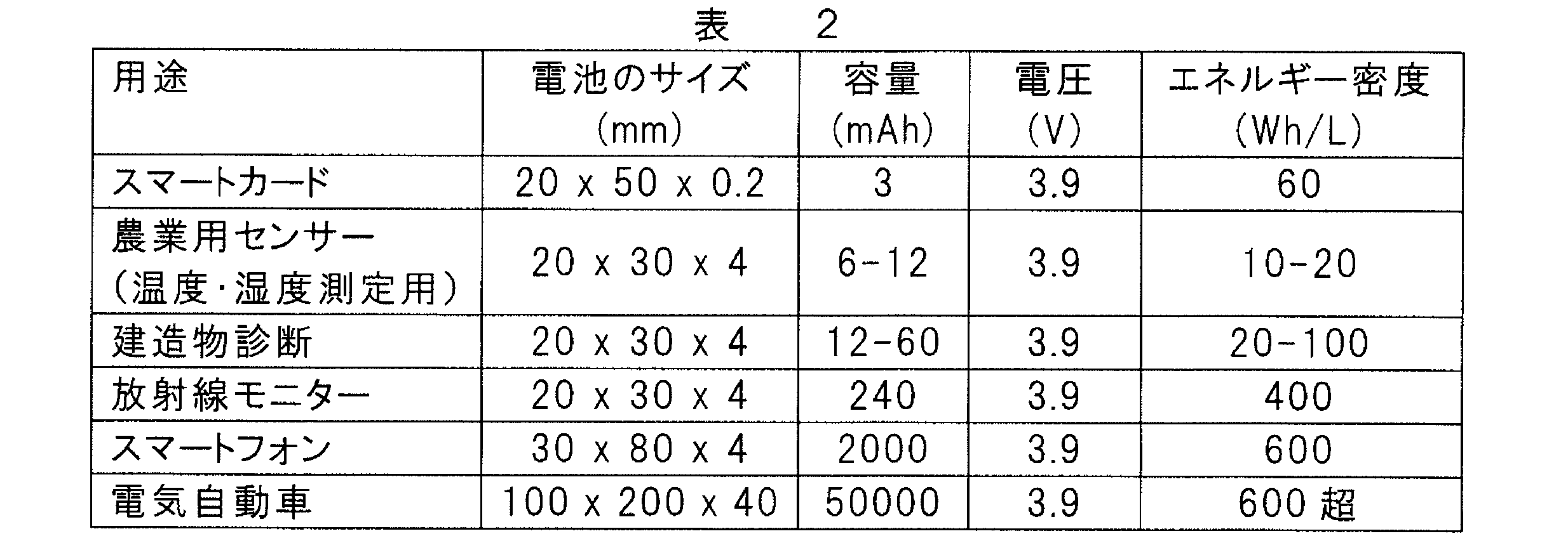
Claims (18)
- 基板と、
前記基板上に配置されるデバイスと、
前記基板上の前記デバイスの周縁部に平面形状が適合するように設けられ、前記デバイスの全部又は一部の外縁形状に適合する相補的な外縁形状を少なくとも一部に有する全固体電池と、
前記デバイス及び前記全固体電池を接続する配線と、
を備えた電池搭載デバイスであって、前記全固体電池が、一定の方向に配向された複数のリチウム遷移金属酸化物粒子からなる配向多結晶体である正極活物質を有する正極層と、リチウムイオン伝導材料で構成される固体電解質層と、負極活物質を有する負極層とを備えてなる、電池搭載デバイス。 - スマートカード、ウェアラブルデバイス及びウェアラブルコンピューターからなる群から選択される少なくとも1つの用途に用いられる、請求項1に記載の電池搭載デバイス。
- 前記全固体電池が、多角形及び/又は円弧を含む表面形状を有する、請求項1又は2に記載の電池搭載デバイス。
- 前記全固体電池の前記相補的な外縁形状が、コの字型、V字型、U字型及び/又は円弧状の切欠き形状を含む、請求項1~3のいずれか一項に記載の電池搭載デバイス。
- 前記電池搭載デバイスが、前記全固体電池を複数個備えてなる、請求項1~4のいずれか一項に記載の電池搭載デバイス。
- 前記基板の中央部に前記デバイスが配置され、前記基板上の前記デバイスが配置されていない隙間領域に前記全固体電池が配置されてなる、請求項5に記載の電池搭載デバイス。
- 前記基板上の前記デバイスの両側に前記全固体電池が配置されてなる、請求項5又は6に記載の電池搭載デバイス。
- 前記基板上の前記デバイスが配置されていない隙間領域の50%以上の領域を前記全固体電池が占有する、請求項5~7のいずれか一項に記載の電池搭載デバイス。
- 前記全固体電池は、
‐ 700Wh/L以上のエネルギー密度を有し、厚みが5mm以下であり、縦及び横の寸法がそれぞれ100mm以下であるか、又は
‐ 600Wh/L以上のエネルギー密度を有し、厚みが2mm以下であり、縦及び横のサイズがそれぞれ50mm以下であるか、又は
‐ 500Wh/L以上のエネルギー密度を有し、厚みが1mm以下であり、縦及び横がそれぞれ50mm以下であるか、又は
‐ 250Wh/L以上のエネルギー密度を有し、厚みが0.5mm以下であり、縦及び横がそれぞれ50mm以下であるか、又は
‐ 100Wh/L以上のエネルギー密度を有し、厚みが0.3mm以下であり、縦及び横がそれぞれ50mm以下であるか、又は
‐ 100~1000Wh/Lのエネルギー密度を有し、厚みが0.1~10mmであり、縦及び横がそれぞれ5~100mmであるか、又は
‐ 250~700Wh/Lのエネルギー密度を有し、厚みが0.3~5mmであり、縦及び横がそれぞれ10~50mmである、請求項1~8のいずれか一項に記載の電池搭載デバイス。 - 前記正極活物質を構成する前記配向多結晶体が5μm以上の厚さを有する、請求項1~9のいずれか一項に記載の電池搭載デバイス。
- 前記正極活物質を構成する前記配向多結晶体が10μm以上の厚さを有する、請求項1~10のいずれか一項に記載の電池搭載デバイス。
- 前記正極活物質を構成する前記配向多結晶体が25μm以上の厚さを有する、請求項1~11のいずれか一項に記載の電池搭載デバイス。
- 前記正極活物質に含まれる前記粒子が、層状岩塩構造又はスピネル構造を有する、請求項1~12のいずれか一項に記載の電池搭載デバイス。
- 前記正極活物質に含まれる前記粒子が、LixM1O2又はLix(M1,M2)O2(式中、0.5<x<1.10、M1はNi,Mn及びCoからなる群から選択される少なくとも一種の遷移金属元素、M2はMg,Al,Si,Ca,Ti,V,Cr,Fe,Cu,Zn,Ga,Ge,Sr,Y,Zr,Nb,Mo,Ag,Sn,Sb,Te,Ba及びBiからなる群から選択される少なくとも一種の元素である)で表される組成を有する、請求項1~13のいずれか一項に記載の電池搭載デバイス。
- 前記組成がLix(M1,M2)O2で表され、M1がNi及びCoであり、M2はMg,Al及びZrからなる群から選択される少なくとも一種であるか、又は前記組成がLixM1O2で表され、M1がNi,Mn及びCoであるか、若しくはM1がCoである、請求項14に記載の電池搭載デバイス。
- 前記正極活物質に含まれる前記粒子が、Lip(Nix,Coy,Alz)O2(式中、0.9≦p≦1.3、0.6<x<0.9、0.1<y≦0.3、0≦z≦0.2、x+y+z=1)で表される組成の層状岩塩構造を有する、請求項1~15のいずれか一項に記載の電池搭載デバイス。
- 前記固体電解質層を構成する前記リチウムイオン伝導材料が、ガーネット系セラミックス材料、窒化物系セラミックス材料、ペロブスカイト系セラミックス材料、リン酸系セラミックス材料、硫化物系セラミックス材料、又は高分子系材料で構成されている、請求項1~16のいずれか一項に記載の電池搭載デバイス。
- 前記正極層が、前記正極活物質と、該正極活物質の前記固体電解質層と反対側の端面に形成された正極集電体とを備え、且つ、前記負極層が、前記負極活物質と、該負極活物質の前記固体電解質層と反対側の端面に形成された負極集電体とを備えた、請求項1~17のいずれか一項に記載の電池搭載デバイス。
Priority Applications (4)
| Application Number | Priority Date | Filing Date | Title |
|---|---|---|---|
| JP2016563540A JPWO2016092889A1 (ja) | 2014-12-09 | 2015-06-25 | 電池搭載デバイス |
| CN201580058425.0A CN107004900A (zh) | 2014-12-09 | 2015-06-25 | 搭载有电池的设备 |
| DE112015005517.7T DE112015005517T5 (de) | 2014-12-09 | 2015-06-25 | Vorrichtung, die mit einer Batterie ausgestattet ist |
| US15/497,582 US10581114B2 (en) | 2014-12-09 | 2017-04-26 | Battery-equipped device |
Applications Claiming Priority (2)
| Application Number | Priority Date | Filing Date | Title |
|---|---|---|---|
| JP2014249371 | 2014-12-09 | ||
| JP2014-249371 | 2014-12-09 |
Related Child Applications (1)
| Application Number | Title | Priority Date | Filing Date |
|---|---|---|---|
| US15/497,582 Continuation US10581114B2 (en) | 2014-12-09 | 2017-04-26 | Battery-equipped device |
Publications (1)
| Publication Number | Publication Date |
|---|---|
| WO2016092889A1 true WO2016092889A1 (ja) | 2016-06-16 |
Family
ID=56107092
Family Applications (2)
| Application Number | Title | Priority Date | Filing Date |
|---|---|---|---|
| PCT/JP2015/068416 Ceased WO2016092889A1 (ja) | 2014-12-09 | 2015-06-25 | 電池搭載デバイス |
| PCT/JP2015/068415 Ceased WO2016092888A1 (ja) | 2014-12-09 | 2015-06-25 | 折り曲げ可能な電池モジュール |
Family Applications After (1)
| Application Number | Title | Priority Date | Filing Date |
|---|---|---|---|
| PCT/JP2015/068415 Ceased WO2016092888A1 (ja) | 2014-12-09 | 2015-06-25 | 折り曲げ可能な電池モジュール |
Country Status (5)
| Country | Link |
|---|---|
| US (1) | US10581114B2 (ja) |
| JP (2) | JPWO2016092888A1 (ja) |
| CN (1) | CN107004900A (ja) |
| DE (1) | DE112015005517T5 (ja) |
| WO (2) | WO2016092889A1 (ja) |
Cited By (2)
| Publication number | Priority date | Publication date | Assignee | Title |
|---|---|---|---|---|
| WO2018092434A1 (ja) * | 2016-11-17 | 2018-05-24 | 株式会社村田製作所 | 全固体電池、電子機器、電子カード、ウェアラブル機器および電動車両 |
| WO2018092484A1 (ja) * | 2016-11-15 | 2018-05-24 | 株式会社村田製作所 | リチウムイオン伝導体、全固体電池、電子機器、電子カード、ウェアラブル機器および電動車両 |
Families Citing this family (17)
| Publication number | Priority date | Publication date | Assignee | Title |
|---|---|---|---|---|
| KR101729702B1 (ko) | 2016-08-10 | 2017-04-24 | 한국기계연구원 | 입체 배열구조를 갖는 신축성 에너지 저장소자 및 신축성 전자 디바이스 |
| JP7075391B2 (ja) * | 2017-02-23 | 2022-05-25 | 株式会社村田製作所 | 糸状電池 |
| JP2018190596A (ja) * | 2017-05-08 | 2018-11-29 | 株式会社シーアイピーソフト | 身体への装着が可能なマグネシウム空気電池 |
| US20190089023A1 (en) * | 2017-09-15 | 2019-03-21 | Dyson Technology Limited | Energy storage system |
| US20190131660A1 (en) * | 2017-10-30 | 2019-05-02 | Ford Global Technologies, Llc | Solid-state battery design using a mixed ionic electronic conductor |
| US12046708B2 (en) | 2017-11-03 | 2024-07-23 | Renata Sa | Foldable flexible assembling of cells for a lithium-ion battery and current collector with carbon based conductive material |
| KR102325924B1 (ko) * | 2017-11-10 | 2021-11-12 | 엔지케이 인슐레이터 엘티디 | 전고체 리튬 전지 및 그 제조 방법 |
| EP3780238B1 (en) | 2018-03-27 | 2026-03-25 | NGK Insulators, Ltd. | Lithium secondary battery |
| JP6496435B1 (ja) | 2018-03-28 | 2019-04-03 | 日本碍子株式会社 | リチウム二次電池及び電池内蔵カード |
| JP7115553B2 (ja) * | 2018-10-10 | 2022-08-09 | 株式会社村田製作所 | 発電素子実装基板、電池パック、電子機器及び電動車両 |
| JP7262057B2 (ja) | 2019-09-30 | 2023-04-21 | パナソニックIpマネジメント株式会社 | 電動工具、及び電池パック |
| JP7262056B2 (ja) * | 2019-09-30 | 2023-04-21 | パナソニックIpマネジメント株式会社 | 電動工具、及び電池パック |
| JPWO2021235395A1 (ja) * | 2020-05-21 | 2021-11-25 | ||
| JP7458241B2 (ja) * | 2020-05-21 | 2024-03-29 | シャープ株式会社 | 電気掃除機の吸込口体、それを備えた電気掃除機および電気掃除装置 |
| KR102928335B1 (ko) * | 2020-10-09 | 2026-02-20 | 아워 넥스트 에너지 인크. | 전기 차량으로의 전력 공급 |
| CN214124022U (zh) * | 2020-12-23 | 2021-09-03 | 比亚迪股份有限公司 | 电子设备 |
| CN118541851A (zh) * | 2022-09-21 | 2024-08-23 | 宁德时代新能源科技股份有限公司 | 电池单体、电池及用电装置 |
Citations (5)
| Publication number | Priority date | Publication date | Assignee | Title |
|---|---|---|---|---|
| JP2000195482A (ja) * | 1998-12-25 | 2000-07-14 | Kyocera Corp | シ―ト状電池 |
| JP2006515952A (ja) * | 2003-01-02 | 2006-06-08 | シンベット・コーポレイション | ソリッドステートのバッテリー給電の装置と製法 |
| JP2010027301A (ja) * | 2008-07-16 | 2010-02-04 | Sony Corp | 薄膜電池の正極の製造方法および薄膜電池の製造方法 |
| JP2012064487A (ja) * | 2010-09-17 | 2012-03-29 | Dainippon Screen Mfg Co Ltd | 電池の製造方法、電池、車両および電子機器 |
| JP2014529848A (ja) * | 2011-08-17 | 2014-11-13 | シンベット・コーポレイションCymbet Corporation | マルチセル薄膜マイクロバッテリー装置 |
Family Cites Families (21)
| Publication number | Priority date | Publication date | Assignee | Title |
|---|---|---|---|---|
| JP2000285881A (ja) * | 1999-03-30 | 2000-10-13 | Kyocera Corp | 薄型電池およびその製造方法 |
| US8431264B2 (en) | 2002-08-09 | 2013-04-30 | Infinite Power Solutions, Inc. | Hybrid thin-film battery |
| US7603144B2 (en) * | 2003-01-02 | 2009-10-13 | Cymbet Corporation | Active wireless tagging system on peel and stick substrate |
| US8029927B2 (en) * | 2005-03-22 | 2011-10-04 | Blue Spark Technologies, Inc. | Thin printable electrochemical cell utilizing a “picture frame” and methods of making the same |
| WO2007061928A2 (en) | 2005-11-17 | 2007-05-31 | Infinite Power Solutions, Inc. | Hybrid thin-film battery |
| TWI419397B (zh) * | 2006-05-12 | 2013-12-11 | 英菲尼特電源設備股份有限公司 | 位於半導體或半導體裝置上的薄膜式電池及其製造方法 |
| US8828066B2 (en) * | 2007-02-01 | 2014-09-09 | Sargon Lazarof | Securing mechanism with dual expandable ends |
| JP2010534381A (ja) * | 2007-03-05 | 2010-11-04 | コーニンクレッカ フィリップス エレクトロニクス エヌ ヴィ | 電気化学エネルギー源及びそのような電気化学エネルギー源を備えた電子装置 |
| JP5132639B2 (ja) | 2008-08-21 | 2013-01-30 | 日本碍子株式会社 | セラミックス材料及びその製造方法 |
| CN102171867A (zh) | 2008-12-24 | 2011-08-31 | 日本碍子株式会社 | 锂二次电池的正极活性物质用的板状粒子、同物质膜及锂二次电池 |
| JP2011009103A (ja) * | 2009-06-26 | 2011-01-13 | Toyota Motor Corp | 全固体リチウム二次電池 |
| JP5376252B2 (ja) | 2009-09-03 | 2013-12-25 | 日本碍子株式会社 | セラミックス材料及びその利用 |
| JP5525388B2 (ja) | 2009-09-03 | 2014-06-18 | 日本碍子株式会社 | セラミックス材料及びその製造方法 |
| JP5458841B2 (ja) * | 2009-12-02 | 2014-04-02 | トヨタ自動車株式会社 | 固体電池モジュールの製造方法、及び当該製造方法により得られる固体電池モジュール |
| JP2011138662A (ja) * | 2009-12-28 | 2011-07-14 | Sumitomo Electric Ind Ltd | 正極体の製造方法、正極体、および非水電解質電池 |
| JP5564649B2 (ja) | 2010-06-23 | 2014-07-30 | 日本碍子株式会社 | リチウム二次電池の正極及びリチウム二次電池 |
| JP5587052B2 (ja) | 2010-06-23 | 2014-09-10 | 日本碍子株式会社 | リチウム二次電池の正極及びリチウム二次電池 |
| JP5887146B2 (ja) * | 2011-08-26 | 2016-03-16 | 積水化学工業株式会社 | リチウムイオン二次電池及びその製造方法 |
| KR101403388B1 (ko) * | 2012-05-07 | 2014-06-03 | 주식회사 엘지화학 | 비정형 구조의 전지셀 및 이를 포함하는 전지모듈 |
| JP2014164836A (ja) * | 2013-02-22 | 2014-09-08 | Ngk Insulators Ltd | 結晶配向した正極活物質板を形成する方法 |
| JP6166584B2 (ja) * | 2013-05-10 | 2017-07-19 | 日本碍子株式会社 | リチウムイオン伝導性固体電解質並びにそれを用いた複合体及び電池 |
-
2015
- 2015-06-25 JP JP2015556312A patent/JPWO2016092888A1/ja active Pending
- 2015-06-25 WO PCT/JP2015/068416 patent/WO2016092889A1/ja not_active Ceased
- 2015-06-25 CN CN201580058425.0A patent/CN107004900A/zh active Pending
- 2015-06-25 DE DE112015005517.7T patent/DE112015005517T5/de not_active Ceased
- 2015-06-25 WO PCT/JP2015/068415 patent/WO2016092888A1/ja not_active Ceased
- 2015-06-25 JP JP2016563540A patent/JPWO2016092889A1/ja active Pending
-
2017
- 2017-04-26 US US15/497,582 patent/US10581114B2/en active Active
Patent Citations (5)
| Publication number | Priority date | Publication date | Assignee | Title |
|---|---|---|---|---|
| JP2000195482A (ja) * | 1998-12-25 | 2000-07-14 | Kyocera Corp | シ―ト状電池 |
| JP2006515952A (ja) * | 2003-01-02 | 2006-06-08 | シンベット・コーポレイション | ソリッドステートのバッテリー給電の装置と製法 |
| JP2010027301A (ja) * | 2008-07-16 | 2010-02-04 | Sony Corp | 薄膜電池の正極の製造方法および薄膜電池の製造方法 |
| JP2012064487A (ja) * | 2010-09-17 | 2012-03-29 | Dainippon Screen Mfg Co Ltd | 電池の製造方法、電池、車両および電子機器 |
| JP2014529848A (ja) * | 2011-08-17 | 2014-11-13 | シンベット・コーポレイションCymbet Corporation | マルチセル薄膜マイクロバッテリー装置 |
Cited By (4)
| Publication number | Priority date | Publication date | Assignee | Title |
|---|---|---|---|---|
| WO2018092484A1 (ja) * | 2016-11-15 | 2018-05-24 | 株式会社村田製作所 | リチウムイオン伝導体、全固体電池、電子機器、電子カード、ウェアラブル機器および電動車両 |
| JPWO2018092484A1 (ja) * | 2016-11-15 | 2019-06-24 | 株式会社村田製作所 | リチウムイオン伝導体、全固体電池、電子機器、電子カード、ウェアラブル機器および電動車両 |
| CN109937506A (zh) * | 2016-11-15 | 2019-06-25 | 株式会社村田制作所 | 锂离子传导体、全固体电池、电子设备、电子卡、可穿戴设备以及电动车辆 |
| WO2018092434A1 (ja) * | 2016-11-17 | 2018-05-24 | 株式会社村田製作所 | 全固体電池、電子機器、電子カード、ウェアラブル機器および電動車両 |
Also Published As
| Publication number | Publication date |
|---|---|
| JPWO2016092889A1 (ja) | 2017-09-21 |
| US20170229733A1 (en) | 2017-08-10 |
| WO2016092888A1 (ja) | 2016-06-16 |
| US10581114B2 (en) | 2020-03-03 |
| DE112015005517T5 (de) | 2017-08-24 |
| JPWO2016092888A1 (ja) | 2017-04-27 |
| CN107004900A (zh) | 2017-08-01 |
Similar Documents
| Publication | Publication Date | Title |
|---|---|---|
| WO2016092889A1 (ja) | 電池搭載デバイス | |
| JP5837266B1 (ja) | 全固体電池を用いた揮発性メモリ用バックアップシステム | |
| CN111868991B (zh) | 全固体电池 | |
| JP6943873B2 (ja) | Ic用電源及びそれを備えた各種ic製品、icへの電力供給方法、並びにicの駆動方法 | |
| JP7553352B2 (ja) | 全固体電池 | |
| WO2015111495A1 (ja) | 全固体電池の各種用途における使用 | |
| JPWO2017065034A1 (ja) | 全固体リチウム電池の製造方法 | |
| WO2021145312A1 (ja) | 固体電池 | |
| WO2022186087A1 (ja) | 固体電池 | |
| CN116615811B (zh) | 固体电解质陶瓷以及固体电池 | |
| CN113574019A (zh) | 固体电解质的前体溶液 | |
| CN115428098A (zh) | 固体电解质陶瓷材料及固体电池 | |
| WO2022107801A1 (ja) | 固体電解質セラミックスおよび固体電池 | |
| JP7211470B2 (ja) | 電極複合体、電池、電子機器 | |
| CN121444258A (zh) | 固体电池 | |
| CN119923734A (zh) | 固体电池 | |
| WO2025069738A1 (ja) | 固体電池 | |
| WO2022107824A1 (ja) | 固体電解質セラミックスおよび固体電池 | |
| WO2022107804A1 (ja) | 固体電解質セラミックスおよび固体電池 |
Legal Events
| Date | Code | Title | Description |
|---|---|---|---|
| 121 | Ep: the epo has been informed by wipo that ep was designated in this application |
Ref document number: 15867116 Country of ref document: EP Kind code of ref document: A1 |
|
| ENP | Entry into the national phase |
Ref document number: 2016563540 Country of ref document: JP Kind code of ref document: A |
|
| WWE | Wipo information: entry into national phase |
Ref document number: 112015005517 Country of ref document: DE |
|
| 122 | Ep: pct application non-entry in european phase |
Ref document number: 15867116 Country of ref document: EP Kind code of ref document: A1 |