WO2016084787A1 - 車両用ドアのドアラッチ装置 - Google Patents
車両用ドアのドアラッチ装置 Download PDFInfo
- Publication number
- WO2016084787A1 WO2016084787A1 PCT/JP2015/082891 JP2015082891W WO2016084787A1 WO 2016084787 A1 WO2016084787 A1 WO 2016084787A1 JP 2015082891 W JP2015082891 W JP 2015082891W WO 2016084787 A1 WO2016084787 A1 WO 2016084787A1
- Authority
- WO
- WIPO (PCT)
- Prior art keywords
- base member
- load receiving
- striker
- receiving portion
- latch device
- Prior art date
- Legal status (The legal status is an assumption and is not a legal conclusion. Google has not performed a legal analysis and makes no representation as to the accuracy of the status listed.)
- Ceased
Links
Images






Classifications
-
- E—FIXED CONSTRUCTIONS
- E05—LOCKS; KEYS; WINDOW OR DOOR FITTINGS; SAFES
- E05B—LOCKS; ACCESSORIES THEREFOR; HANDCUFFS
- E05B77/00—Vehicle locks characterised by special functions or purposes
- E05B77/42—Means for damping the movement of lock parts, e.g. slowing down the return movement of a handle
-
- B—PERFORMING OPERATIONS; TRANSPORTING
- B60—VEHICLES IN GENERAL
- B60J—WINDOWS, WINDSCREENS, NON-FIXED ROOFS, DOORS, OR SIMILAR DEVICES FOR VEHICLES; REMOVABLE EXTERNAL PROTECTIVE COVERINGS SPECIALLY ADAPTED FOR VEHICLES
- B60J5/00—Doors
- B60J5/04—Doors arranged at the vehicle sides
- B60J5/06—Doors arranged at the vehicle sides slidable; foldable
-
- E—FIXED CONSTRUCTIONS
- E05—LOCKS; KEYS; WINDOW OR DOOR FITTINGS; SAFES
- E05B—LOCKS; ACCESSORIES THEREFOR; HANDCUFFS
- E05B77/00—Vehicle locks characterised by special functions or purposes
- E05B77/34—Protection against weather or dirt, e.g. against water ingress
-
- E—FIXED CONSTRUCTIONS
- E05—LOCKS; KEYS; WINDOW OR DOOR FITTINGS; SAFES
- E05B—LOCKS; ACCESSORIES THEREFOR; HANDCUFFS
- E05B81/00—Power-actuated vehicle locks
- E05B81/12—Power-actuated vehicle locks characterised by the function or purpose of the powered actuators
- E05B81/14—Power-actuated vehicle locks characterised by the function or purpose of the powered actuators operating on bolt detents, e.g. for unlatching the bolt
-
- E—FIXED CONSTRUCTIONS
- E05—LOCKS; KEYS; WINDOW OR DOOR FITTINGS; SAFES
- E05B—LOCKS; ACCESSORIES THEREFOR; HANDCUFFS
- E05B83/00—Vehicle locks specially adapted for particular types of wing or vehicle
- E05B83/36—Locks for passenger or like doors
- E05B83/40—Locks for passenger or like doors for sliding doors
-
- E—FIXED CONSTRUCTIONS
- E05—LOCKS; KEYS; WINDOW OR DOOR FITTINGS; SAFES
- E05B—LOCKS; ACCESSORIES THEREFOR; HANDCUFFS
- E05B85/00—Details of vehicle locks not provided for in groups E05B77/00 - E05B83/00
- E05B85/02—Lock casings
Definitions
- the present invention relates to a door latch device assembled to a vehicle door.
- Patent Document 1 discloses an example of this type of door latch device.
- components are assembled between a metal first base member (base plate) and a metal second base member (cover plate).
- the first base member includes a striker receiving groove that is open to receive the striker.
- the present invention has been made in view of the above points, and one of its purposes is a door latch device assembled to a vehicle door, which receives an input load from a striker without increasing the device weight more than necessary. It is to provide effective technology.
- a door latch device for a vehicle door includes a first base member, a latch, a second base member, and a load receiving structure.
- the first base member is a metal member having a striker receiving groove configured to allow the striker to enter.
- the latch is configured to be rotatable in both directions of a meshing direction that engages with the striker and a meshing release direction in which the meshing with the striker is released, with a latch rotation shaft assembled to the first base member as a center.
- the second base member is a metal member that is disposed to face the first base member with the latch interposed therebetween and is fixed to the first base member.
- the load receiving structure is configured to receive an input load when the striker in a state of entering the striker receiving groove of the first base member is urged toward the second base member, one of the first base member and the second base member.
- the first load receiving portion that extends from the base member toward the other base member and the second load receiving portion that is provided on the other base member serve a function. According to this load receiving structure, it is possible to efficiently receive the input load from the striker while complementing the respective strengths of the first load receiving portion of one base member and the second load receiving portion of the other base member. As a result, it is possible to receive an input load from the striker without increasing the apparatus weight due to the weight of the first base member 1 or the second base member more than necessary.
- the load receiving structure has a state in which the first load receiving portion of one base member and the second load receiving portion of the other base member are not connected to each other and enter the striker receiving groove. It is preferable that each load receiving portion is configured to face the striker. In this case, since a structure for connecting the first load receiving portion and the second load receiving portion to each other is not required, it is easy to assemble the other base member to one base member, and it is advantageous for weight reduction. .
- the load receiving structure is configured such that the strength of the first load receiving portion of the first base member as one base member is the strength of the second load receiving portion of the second base member as the other base member.
- the striker in a state of exceeding and entering the striker receiving groove is configured to abut on the first load receiving portion in preference to the second load receiving portion when urged toward the second base member. preferable.
- the input load from the striker is first dispersed by the first load receiving portion, the input load can be prevented from reaching the second load receiving portion.
- the level of the load can be kept low.
- the second base member having the second load receiving portion can be reduced in size without reducing the strength against the striker, and the door latch device can be reduced in weight and cost.
- the first load receiving portion extends from two different base end regions of the first base member, respectively, and includes two extending pieces that define an entry space for the striker, and two extending portions It is preferable to be configured as an arch-shaped plate portion including a connecting piece that connects the extended tips of the pieces. Thereby, it is possible to reduce the weight of the first load receiving portion with a simple structure while ensuring the strength necessary for the first load receiving portion.
- the first base member has a throttle portion outside the entry space and adjacent to the extension piece.
- the drawn portion is a portion formed when the first base member is formed by press drawing. Thereby, the intensity
- the first load receiving portion is configured to extend along the panel extending surface of the vehicle body panel to which the vehicle door is attached when the vehicle door is closed. Is preferred. As a result, it is possible to realize a structure in which dust, water, and the like are difficult to enter into the vehicle from between the corners between the door latch device and the vehicle body panel.
- the door latch device assembled to the vehicle door can receive the input load from the striker without increasing the device weight more than necessary.
- FIG. 1 is a plan view showing a schematic configuration of a vehicle 1 including a sliding vehicle door 10.
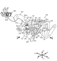
- FIG. 2 is a perspective view of the first door latch device 100 assembled to the vehicle door 10 in FIG.
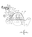
- FIG. 3 is a view of the first door latch device 100 in FIG. 4 is a view of the first door latch device 100 in FIG.
- FIG. 5 is an exploded perspective view of the first door latch device 100 in FIG.
- FIG. 6 is a view showing the coil spring 160 constituting the first door latch device 100 and its peripheral structure.
- FIG. 7 is a view for explaining the function of the spring locking portion 142 of the holding member 140.
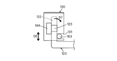
- FIG. 8 is a view for explaining the characteristics of the cap 130.
- FIG. 9 is a view for explaining the configuration of the first load receiving portion 103 of the first base member 101.
- FIG. 10 is a diagram for explaining the function of the first load receiving portion 103 in FIG.
- FIG. 11 is a view for explaining the configuration of the first load receiving portion 203 according to the modified example of the first load receiving portion 103 in FIG. 9.
- FIG. 12 is a view for explaining the configuration of the first load receiving portion 303 according to the modified example of the first load receiving portion 103 in FIG. 9.
- FIG. 13 is a diagram for explaining the configuration of the first load receiving portion 403 according to the modified example of the first load receiving portion 103 in FIG. 9.
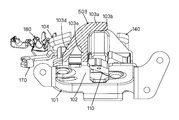
- FIG. 14 is a diagram for explaining a configuration of a first load receiving portion 503 according to a modified example of the first load receiving portion 103 in FIG.
- the vehicle door 10 includes a slide-type vehicle door (also referred to as “vehicle door” or “slide door”) 10 corresponding to the rear seat of the vehicle.
- the vehicle door 10 is configured to be operable between a fully closed state in which a passenger entrance for getting on and off is completely closed and a fully open state in which the entrance is opened so that the opening area is maximized. Yes.
- the vehicle door 10 is retracted obliquely backward from the fully closed state, and is fully opened by retreating straight from the middle.
- a plurality of elements including the first door latch device 100, the second door latch device 100a, and the third door latch device 100b are assembled to the vehicle door 10.
- Both the first door latch device 100 and the second door latch device 100a fulfill the function of holding the vehicle door 10 in the closed state.
- the third door latch device 100b fulfills the function of holding the vehicle door 10 in the fully opened state.
- a striker 20 corresponding to each of the three door latch devices 100, 100a, 100b is provided on the
- the first door latch device 100 holds the vehicle door 10 in a closed holding state (a state in which the vehicle door 10 is closed and held) and This is for setting to a closed holding release state (a state in which the closed holding state of the vehicle door 10 is released).
- the door latch device 100 includes a first base member 101 and a second base member 104, both of which are made of metal, and a plurality of components (latches 110 described later) between the first base member 101 and the second base member 104. And pole 120).
- the second base member 104 is disposed to face the first base member 101 with a plurality of components interposed therebetween, and is connected to the first base member 101 via pins 105 and 106 described later.
- the first base member 101 is a plate-like member having a substantially uniform plate thickness.
- the first base member 101 here corresponds to “one base member” and “first base member” of the present invention, and the first load receiving portion 103 of the first base member 101 is the “first load” of the present invention.
- the base body 102 of the first base member 101 has a through-hole 102a formed therethrough for assembling a shaft-shaped latch pin (also referred to as “latch rotation shaft”) 105 and a shaft-shaped pole pin (“pole rotation”).
- a through-hole 102b formed so as to pass through for assembling 106 and a striker receiving groove 102c into which the striker 20 can enter is provided.
- the first load receiving portion 103 extends from the first base member 101 toward the second base member 104, and receives a lateral load received from the striker 20 in a state of entering the striker receiving groove 102c, that is, in FIG. It is configured as a load receiving portion (hereinafter also referred to as “first load receiving portion”) that receives a load acting on the vehicle right side Y2.
- the second base member 104 is a plate-like member having a substantially uniform plate thickness, and in the same manner as the first load receiving portion 103, the second base member 104 is a lateral member received from the striker 20 in a state of entering the striker receiving groove 102c.
- a second load receiving portion 104c that receives a load is provided.
- the second base member 104 here corresponds to the “other base member” and the “second base member” of the present invention, and the second load receiving portion 104c of the second base member 104 corresponds to the “second load” of the present invention. Corresponds to "receiving part".
- the door latch device 100 receives the input load when the striker 20 that has entered the striker receiving groove 102c is urged toward the second base member 104 and the first load receiving portion 103.
- a load receiving structure that is received by both of the two load receiving portions 104c is provided.
- the input load from the striker 20 can be efficiently performed while complementing the respective strengths of the first load receiving portion 103 of the first base member 101 and the second load receiving portion 104c of the second base member 104. Can receive.
- the latch pin 105 and the pole pin 106 are preferably pin members having the same shape. Thereby, the same pin member can be diverted.
- Each of these pins 105 and 106 is preferably provided with flange-shaped flange portions 105a and 106a at one shaft end. In this case, since the assembling direction of the pins 105 and 106 with respect to the base main body 102 of the first base member 101 is determined in one direction, the assembling property of the pins 105 and 106 is improved.
- the second base member 104 has attachment holes 104a and 104b formed therethrough.
- the second base member 104 and the open lever 170 are connected so as to be relatively rotatable by an open lever pin 107 inserted into both the mounting hole 104a of the second base member 104 and the mounting hole 170a of the open lever 170.
- the open lever 170 is configured to be rotatable about the open lever pin 107 with respect to the second base member 104.
- the open lever 170 includes a first arm portion 171 to which one end portion of the open cable W is coupled, a second arm portion 172 that indirectly engages a pole 120 described later via a cap 130 made of a resin material, The metal member provided with.
- a cable clamp 180 for clamping the covering portion covering the open cable W is attached to the attachment hole 104b of the second base member 104.
- the latch pin 105 provided in the base main body 102 of the first base member 101 is inserted into the insertion hole 110a of the latch 110. Therefore, the latch 110 is rotatably supported by the latch pin 105, and is engaged in a meshing direction that engages with the striker 20 provided on the vehicle body around the latch pin 105 and in a meshing release direction in which the meshing with the striker 20 is released. It is configured to be able to rotate in both directions.
- the latch 110 is set at a plurality of positions including an unlatch position, a full latch position, and a half latch position between the unlatch position and the full latch position.
- the latch 110 includes a first locking claw 111 and a second locking claw 112 extending substantially in parallel, and a region where the locking claws 111 and 112 face each other is a striker receiving portion for receiving the striker 20. 113.
- the latch 110 is elastically biased in a latch release direction (a direction indicated by an arrow D1 in FIG. 5) toward an unlatched position by a coil spring (elastic spring member) 150 formed in a coil shape by a linear metal material.
- the latch 110 corresponds to the “latch” of the present invention.
- the striker 20 that has entered the striker receiving groove 102c of the first base member 101 receives the striker while pressing the opposing surface on the striker receiving portion 113 side of the first locking claw 111 of the latch 110. Enter part 113.
- the latch 110 engages with the striker 20 from the unlatched position and rotates in the engagement direction (the direction opposite to the direction indicated by the arrow D1 in FIG. 5) around the latch pin 105. To do. That is, the latch 110 is rotated in the locking direction in which the latch 110 is engaged with the striker 20 and locked.
- the pole pin 106 provided on the base main body 102 of the first base member 101 is inserted into the insertion hole 120a of the pole 120. Therefore, the pole 120 is rotatably supported by the pole pin 106.
- the pole 120 includes an extending portion 121 that extends toward the latch 110, and a restriction position that restricts the rotation of the latch 110 with respect to the striker 20 in the disengagement direction around the pole pin 106 by the extending portion 121. And the non-regulated position where the rotation of the latch 110 in the meshing release direction with respect to the striker 20 is not restricted.
- the pole 120 is elastically biased in a direction indicated by an arrow D2 in FIG. 5 from a non-regulated position to a regulated position by a coil spring (elastic spring member) 160 formed in a coil shape by a linear metal material. ing.
- the pole 120 further includes a mounting shaft 122 that extends in a shaft shape in a predetermined direction to hold the resin cap 130, and a pole that extends from the mounting shaft 122 and engages a pole stopper 144 of a holding member 140 described later.
- the cap 130 is formed in a cylindrical shape, and is held integrally with the pole 120 by inserting the mounting shaft 122 into the in-cylinder space 130a.
- the mounting shaft 122 has a cylindrical structure with a square cross-sectional shape, and is configured such that the cross-sectional shape of the in-cylinder space 130a is the same as the cross-sectional shape of the mounting shaft 122. Is preferred.
- the cap 130 includes a spring engagement groove 131 formed in a concave shape on the outer surface thereof.
- the holding member 140 includes a cylindrical boss portion 141 extending in the same direction as the mounting shaft 122 to hold the coil portion 161 having a circular cross section of the coil spring 160, and a coil portion 161 held by the boss portion 141.
- the coil spring 160 is configured such that the spring end portion 163 of the other spring line extending radially outward from the coil portion 161 held by the boss portion 141 engages with the spring engagement groove 131 of the cap 130. ing. In this case, the cap 130 inserted into the mounting shaft 122 of the pole 120 can be prevented from coming out of the mounting shaft 122 by the spring end 163 of the coil spring 160.
- the pole pin 106 inserted into the insertion hole 120a of the pole 120 is caulked and fixed to the second base member 104 at the shaft end opposite to the flange portion 105a while being inserted into the cylinder of the boss portion 141. Has been.
- the movement of the coil spring 160 in the withdrawal direction is restricted by the second base member 104 so that the coil portion 161 does not escape from the boss portion 141 of the holding member 140. That is, the coil spring 160 is assembled to the holding member 140 in a state where movement of the mounting shaft 122 in the axial direction is restricted.
- the cap 130 is prevented from coming off from the mounting shaft 122 of the pole 120. In this case, the cap 130 is prevented from slipping out indirectly by the second base member 104 that restricts the coil spring 160 from slipping out of the boss portion 141.
- the cap A retaining mechanism that prevents the 130 from coming off the mounting shaft 122 of the pole 120 is configured. According to this retaining mechanism, since the cap 130 attached to the pole 120 can be held so as not to be detached, the operation reliability of the open lever 170 can be ensured. Further, since the existing coil spring 160 assigned to the pole 120 is used to hold the cap 130, it is not necessary to prepare a dedicated member, which is advantageous in terms of cost.
- the cap 130 is prevented from coming off by a simple structure using the engagement between the spring end 163 of one spring wire extending from the coil portion 161 of the coil spring 160 and the spring engagement groove 131 of the cap 130. It can be carried out.
- the latch pin 105 is also crimped and fixed to the second base member 104 in the same manner, and thereby the movement of the coil spring 150 in the withdrawal direction is restricted by the second base member 104.
- the open lever 170 when the open cable W is pulled in the direction indicated by the arrow D3 in FIG. 5 according to the opening operation of the vehicle door 10, the open lever 170 is centered on the open lever pin 107 in FIG. It rotates in the direction shown by arrow D4. At this time, the second arm portion 172 of the open lever 170 is indirectly engaged with the mounting shaft 122 in a state of being in contact with the outer surface (arc surface) of the resin cap 130, and the pole is passed through the cap 130. 120 is urged to rotate from the restricted position to the unregulated position against the elastic urging force of the coil spring 160 in the direction opposite to the direction indicated by the arrow D2 in FIG.
- the pole 120 is set to an unregulated position that does not restrict the rotation of the latch 110 in the meshing release direction with respect to the striker 20.
- the second arm portion 172 of the metal open lever 170 is indirectly engaged with the metal pole 120 via the resin cap 130, the second arm portion 172 of the metal open lever 170 is engaged.
- the sliding resistance of the open lever 170 can be suppressed and the open lever 170 can be operated smoothly.
- the coil spring 160 has one spring end 162 extending from the coil portion 161 locked to the spring locking portion 142 of the second base member 104. More specifically, as shown in FIG. 6, the spring end portion 162 includes a first region 162 a that extends radially outward from the coil portion 161 having a circular cross section and extends linearly, and a first region 162 a. The second region 162b is bent and extends linearly, and the second region 162b is engaged with the locking surface 142a of the spring locking part 142. The second region 162b of the spring end portion 162 extends in the same direction as the coil center line L of the coil portion 161 (see FIG. 6).
- the locking surface 142a of the spring locking portion 142 is a curved surface curved along the circumferential direction of the second region 162b of the spring end 162 having a circular cross section.
- the second region 162 b of the spring end 162 of the coil spring 160 has a peripheral surface that contacts the locking surface 142 a of the spring locking portion 142.
- the locking surface 142a can be moved along the curved surface in the direction indicated by the arrow D5.
- the second region 162b of the spring end 162 moves freely along the locking surface 142a of the spring locking portion 142 to absorb the mounting error. it can.
- the other spring end 163, which is a part of the coil spring 160 is a member extending linearly outward in the radial direction from the coil section 161 having a circular cross section. It engages with the groove 131 and abuts against the mounting shaft 122 of the pole 120. That is, a part of the attachment shaft 122 is exposed at the groove bottom of the spring engagement groove 131. For this reason, before the operation of the open lever 170, the pawl 120 is elastically loaded from the coil spring 160 by the pawl engaging portion 123 provided on the mounting shaft 122 abutting against the pawl stopper 144 provided on the holding member 140. Is held in the restricted position.
- part of the elastic load of the coil spring 160 acts on the attachment shaft 122 via the spring end 163, and the elastic load acting on the attachment shaft 122 is received by the pole stopper 144 that abuts on the pole engaging portion 123. It is done.
- the spring engagement groove 131 with which the spring end 163 engages with the longitudinal extension direction of the attachment shaft 122 (the axial direction indicated by the arrow D ⁇ b> 6 in FIG. 8). It is preferable to set the pole engaging portions 123 at positions close to each other. As a result, the mounting shaft 122 of the pole 120 causes the rotational moment in the direction indicated by the arrow D7 received when the pole engaging portion 123 abuts on the pole stopper 144 due to the elastic load received from the spring end 163 of the coil spring 160. It can be kept low. As a result, the occurrence of rattling of the pole 120 can be suppressed.
- the load input from the second arm portion 172 when the open lever 170 is operated is transmitted to the mounting shaft 122 through the cap 130, and is further engaged with the spring engagement groove 131 of the cap 130 from the mounting shaft 122. It is transmitted directly to the spring end 163.
- a configuration in which the attachment shaft 122 is not exposed at the groove bottom of the spring engagement groove 131 may be employed. In this configuration, the load input from the second arm portion 172 of the open lever 170 is moved from the mounting shaft 122 to the spring end portion 163 engaged with the spring engagement groove 131 of the cap 130. It is transmitted indirectly through the resin part.
- the first load receiving portion 103 of the first base member 101 will be described with reference to FIGS. 9 and 10.
- the surface of the load receiving portion is hatched to clarify the shape of the first load receiving portion.
- the first load receiving portion 103 of the present embodiment is along the panel extending surface of the vehicle body panel (vehicle body panel 2 in FIG. 3) to which the vehicle door 10 is attached when the vehicle door 10 is closed. It is a plate-like part that extends. In this case, it becomes difficult for dust, water, and the like to enter the vehicle from between the corners between the door latch device 100 and the vehicle body panel 2.
- one connecting piece 103a and three extending pieces 103c, 103d, 103e are integrated, and the plate width of any piece is configured to exceed the plate thickness.
- the connecting piece 103a contacts the striker 20 on the inner wall surface (surface corresponding to the plate thickness) 103b so as to receive a load in the direction in which the striker 20 faces the second base member 104 (the direction indicated by the white arrow in FIG. 9). It is a contactable part.
- Each of the three extending pieces 103c, 103d, 103e extends from three different base end regions 101c, 101d, 101e of the base main body 102 toward the connecting piece 103a, and the extending tips thereof are connected to the connecting piece 103a.
- the first load receiving portion 103 forms an arch-shaped (also referred to as “U-shaped” or “hook-shaped”) plate portion by the connecting piece 103a and the two extending pieces 103c and 103d.
- a space 103f defined by the extending piece 103c and the extending piece 103e is an entry space for the striker 20 to enter.
- a space 103g defined by the extending piece 103d and the extending piece 103e serves as an opening region for reducing the weight of the first load receiving portion 103.
- required by the 1st load receiving part 103 is securable, aiming at weight reduction of the 1st load receiving part 103 with a simple structure.
- the length of the connecting piece 103a (the length in the left-right direction in FIG. 9) is preferably less than the distance between the proximal end region 101c of the extending piece 103c and the proximal end region 101d of the extending piece 103d.
- the first base member 101 is formed by press drawing, the first base member 101 is based on a position close to a relatively strong drawing point (drawing points 101a and 101b in FIG. 9) of each part of the first base member 101. It is preferable to set the end regions 101c and 101d.
- the first base member 101 is provided with a throttle part (a part corresponding to the throttle points 101a and 101b) at a part outside the space 103f (entrance space) and adjacent to the extension pieces 103c and 103d.
- a throttle part a part corresponding to the throttle points 101a and 101b
- This diaphragm portion corresponds to the “diaphragm portion” of the present invention. This is effective in further increasing the strength of the first load receiving portion 103 configured as an arch-shaped plate portion.
- the first load receiving portion 103 may be configured as one extending piece in which the extending piece 103d and the extending piece 103e are integrated with the space 103g omitted.
- the first load receiving portion 103 includes two extending pieces (an extending piece 103c, an extending piece in which the extending piece 103d and the extending piece 103e are integrated), and these two extending pieces. It becomes an arch-shaped plate part provided with the connection piece 103a which connects the extension tips of the extension pieces.
- the first load receiving portion 103 of this configuration it is possible to resist a load received from the striker 20 by a structure in which the base main body portion 102 of the first base member 101 is extended to the second base member 104 side. .
- the thickness of the first base member 101 is greater than the thickness of the second base member 104
- the strength of the first load receiving portion 103 is greater than the strength of the second base member 104.
- the input load from the striker 20 is first dispersed by the first load receiving portion 103, the input load can be prevented from reaching the second load receiving portion 104c.
- the level of the load can be kept low.
- the second base member 104 including the second load receiving portion 104c can be reduced in size without reducing the strength of the striker 20, and the door latch device 100 can be reduced in weight and cost.
- the first load receiving portion 103 of the first base member 101 and the second load receiving portion 104c of the second base member 104 enter the striker receiving portion 113 without being connected to each other.
- Each of the load receiving portions is configured to face the striker 20 in a state of being performed.
- the second base member 104 can be easily assembled to the first base member 101. This is advantageous for weight reduction. If a configuration in which the first load receiving portion 103 and the second load receiving portion 104c are connected instead of this configuration is adopted, it is advantageous to increase the strength against the input load from the striker 20.
- the structure of the first load receiver 103 can be changed to a structure as shown in FIGS. 11 to 14, for example, if necessary.
- the same reference numerals are given to the components of the first load receiving portion 103, and the description of the same components is omitted.
- the first load receiving portion 203 shown in FIG. 11 has a structure in which one extending piece 103e is omitted from the components of the first load receiving portion 103.
- the first load receiving portion 303 shown in FIG. 12 has a structure in which one extending piece 103 d is omitted from the components of the first load receiving portion 103.
- the first load receiving portion 403 shown in FIG. 13 has a structure in which the two extending pieces 103 d and 103 e are omitted from the components of the first load receiving portion 103.
- the first load receiving portion 503 shown in FIG. 14 has a structure in which one extending piece 103 c is omitted from the components of the first load receiving portion 103.
- the first load receiving portion includes an element that receives a load from the striker 20 and at least one element that connects the element to the base main body portion 102.
- the weight can be reduced as compared with the first load receiving portion 103.
- the present invention is not limited to the above exemplary embodiment, and various applications and modifications are possible.
- each of the following embodiments to which the above embodiment is applied can be implemented.
- the shape of the first load receiving portions 103 to 503 is not limited to the above embodiment, and various modifications can be made as necessary.
- the first load receiving portion may be replaced with a plate shape, and may have a bar shape having a cross section such as a circle, an ellipse, a rectangle, or a polygon.
- the first load receiving portion 103 shown in FIG. 9 the case where the length of the connecting piece 103a is less than the distance between the proximal end region 101c of the extending piece 103c and the proximal end region 101d of the extending piece 103d is described.
- the length of the connecting piece 103a is substantially the same as the interval between the proximal end region 101c and the proximal end region 101d of the extending piece 103d, or a configuration exceeding the interval can be employed.
- the first load receiving portion 103 may constitute a part of the first base member 101 or may be a separate member joined to the first base member 101 by welding or the like. .
- the first load receiving portion is configured by the portion extending from the first base member 101 toward the second base member 104.
- the second base member 104 to the first base member 101 is configured.
- a 1st load receiving part can also be comprised by the site
- the door latch device 100 assembled to the slide type vehicle door 10 corresponding to the rear seat of the vehicle has been described.
- the essential structure of the door latch device 100 is changed to other parts of the vehicle. It can apply to the door for vehicles provided in.
Landscapes
- Engineering & Computer Science (AREA)
- Mechanical Engineering (AREA)
- Lock And Its Accessories (AREA)
Abstract
本発明に係るドアラッチ装置は、ストライカ受容溝を有する金属製の第1ベース部材と、第1ベース部材に組付けられたラッチ回動軸を中心にしてストライカに噛み合う噛み合い方向及びストライカとの噛み合いが解除される噛み合い解除方向の双方向に回動可能に構成されたラッチと、ラッチを挟んで第1ベース部材と対向して配置され且つ第1ベース部材に固定された金属製の第2ベース部材と、第1ベース部材のストライカ受容溝に進入した状態のストライカが第2ベース部材に向けて付勢されたときの入力荷重を、第1ベース部材及び第2ベース部材のうちの一方のベース部材から他方のベース部材に向けて延出した第1荷重受け部と他方のベース部材に設けられた第2荷重受け部との双方によって受ける荷重受け構造と、を含む。
Description
本発明は、車両用ドアに組付けられるドアラッチ装置に関する。
下記特許文献1には、この種のドアラッチ装置の一例が開示されている。このドアラッチ装置では、金属製の第1ベース部材(ベースプレート)と金属製の第2ベース部材(カバープレート)との間に構成要素が組み付けられている。第1ベース部材は、ストライカを受け入れるために開口形成されたストライカ受容溝を備えている。
(発明が解決しようとする課題)
ところで、上記のドアラッチ装置では、第1ベース部材のストライカ受容溝に進入した状態のストライカが進入方向と交差する方向(第2ベース部材に向かう方向)に付勢される場合が想定されるため、この場合にストライカから入力される入力荷重を受けるための構造が必要になる。そこで、従来では、第2ベース部材の板厚を増やして強度を高めこの第2ベース部材によってストライカからの入力荷重を受ける構造を採用するのが一般的であった。しかしながら、このような構造では、第2ベース部材全体の板厚を増やすことになりドアラッチ装置の重量が増えるとともにコストが高くなる。
ところで、上記のドアラッチ装置では、第1ベース部材のストライカ受容溝に進入した状態のストライカが進入方向と交差する方向(第2ベース部材に向かう方向)に付勢される場合が想定されるため、この場合にストライカから入力される入力荷重を受けるための構造が必要になる。そこで、従来では、第2ベース部材の板厚を増やして強度を高めこの第2ベース部材によってストライカからの入力荷重を受ける構造を採用するのが一般的であった。しかしながら、このような構造では、第2ベース部材全体の板厚を増やすことになりドアラッチ装置の重量が増えるとともにコストが高くなる。
本発明は、上記の点に鑑みてなされたものであり、その目的の1つは、車両用ドアに組付けられるドアラッチ装置において、装置重量を必要以上に増やすことなくストライカからの入力荷重を受けるのに有効な技術を提供することである。
(課題を解決するための手段)
上記目的を達成するため、本発明に係る車両用ドアのドアラッチ装置は、第1ベース部材、ラッチ、第2ベース部材及び荷重受け構造を含む。第1ベース部材は、ストライカが進入するよう構成されるストライカ受容溝を有する金属製の部材である。ラッチは、第1ベース部材に組付けられたラッチ回動軸を中心にして、ストライカに噛み合う噛み合い方向及びストライカとの噛み合いが解除される噛み合い解除方向の双方向に回動可能に構成される。第2ベース部材は、ラッチを挟んで第1ベース部材と対向して配置され、且つ第1ベース部材に固定された金属製の部材である。荷重受け構造は、第1ベース部材のストライカ受容溝に進入した状態のストライカが第2ベース部材に向けて付勢されたときの入力荷重を、第1ベース部材及び第2ベース部材のうちの一方のベース部材から他方のベース部材に向けて延出した第1荷重受け部と他方のベース部材に設けられた第2荷重受け部との双方によって受ける機能を果たす。この荷重受け構造によれば、一方のベース部材の第1荷重受け部と他方のベース部材の第2荷重受け部のそれぞれの強度を補完しつつストライカからの入力荷重を効率良く受けることができる。その結果、第1ベース部材1や第2ベース部材の重量に起因する装置重量を必要以上に増やすことなくストライカからの入力荷重を受けることが可能になる。
上記目的を達成するため、本発明に係る車両用ドアのドアラッチ装置は、第1ベース部材、ラッチ、第2ベース部材及び荷重受け構造を含む。第1ベース部材は、ストライカが進入するよう構成されるストライカ受容溝を有する金属製の部材である。ラッチは、第1ベース部材に組付けられたラッチ回動軸を中心にして、ストライカに噛み合う噛み合い方向及びストライカとの噛み合いが解除される噛み合い解除方向の双方向に回動可能に構成される。第2ベース部材は、ラッチを挟んで第1ベース部材と対向して配置され、且つ第1ベース部材に固定された金属製の部材である。荷重受け構造は、第1ベース部材のストライカ受容溝に進入した状態のストライカが第2ベース部材に向けて付勢されたときの入力荷重を、第1ベース部材及び第2ベース部材のうちの一方のベース部材から他方のベース部材に向けて延出した第1荷重受け部と他方のベース部材に設けられた第2荷重受け部との双方によって受ける機能を果たす。この荷重受け構造によれば、一方のベース部材の第1荷重受け部と他方のベース部材の第2荷重受け部のそれぞれの強度を補完しつつストライカからの入力荷重を効率良く受けることができる。その結果、第1ベース部材1や第2ベース部材の重量に起因する装置重量を必要以上に増やすことなくストライカからの入力荷重を受けることが可能になる。
上記構成のドアラッチ装置では、荷重受け構造は、一方のベース部材の第1荷重受け部と他方のベース部材の第2荷重受け部とが互いに連結されることなく、ストライカ受容溝に進入した状態のストライカに各荷重受け部が対向するように構成されるのが好ましい。この場合、第1荷重受け部及び第2荷重受け部を互いに連結するための構造を要しないため、一方のベース部材に対して他方のベース部材を組付け易くなり、また軽量化について有利である。
上記構成のドアラッチ装置では、荷重受け構造は、一方のベース部材としての第1ベース部材の第1荷重受け部の強度が他方のベース部材としての第2ベース部材の第2荷重受け部の強度を上回り、且つストライカ受容溝に進入した状態のストライカが第2ベース部材に向けて付勢されたときに第2荷重受け部に優先して第1荷重受け部に当接するように構成されるのが好ましい。この場合、ストライカからの入力荷重が最初に第1荷重受け部によって分散されるため、当該入力荷重が第2荷重受け部に及ぶのを阻止することができる。或いは、第1荷重受け部がストライカからの入力荷重によって変形してストライカから第2荷重受け部に荷重が及ぶ場合であっても、その荷重のレベルを低く抑えることができる。その結果、ストライカに対する強度低下させることなく第2荷重受け部を備える第2ベース部材を小型化することができ、ドアラッチ装置の軽量化及び低コスト化が可能になる。
上記構成のドアラッチ装置では、第1荷重受け部は、第1ベース部材の異なる2つの基端領域からそれぞれ延出してストライカのための進入空間を区画する2つの延出片と、2つの延出片の延出先端同士を連結する連結片と、を備えるアーチ状のプレート部分として構成されるのが好ましい。これにより、簡単な構造で、第1荷重受け部に必要な強度を確保しつつ、第1荷重受け部を軽量化することができる。
上記構成のドアラッチ装置では、第1ベース部材は、進入空間の外側であって且つ延出片に隣接する部位に絞り部を有するのが好ましい。この絞り部は、第1ベース部材をプレス絞り加工によって成形する際に形成される部位である。これにより、アーチ状のプレート部分として構成された第1荷重受け部の強度を更に高めることができる。
上記構成のドアラッチ装置では、第1荷重受け部は、車両用ドアが閉じられたときに当該車両用ドアが被着される車体パネルのパネル延在面に沿って延在するよう構成されるのが好ましい。これにより、ドアラッチ装置と車体パネルとの間の隅間からダストや水等が車内に入り込み難い構造を実現できる。
以上のように、本発明によれば、車両用ドアに組付けられるドアラッチ装置において、装置重量を必要以上に増やすことなくストライカからの入力荷重を受けることが可能になった。
以下、本発明の実施形態を複数の図面を参照しながら説明する。尚、これらの図面では、車両前方及び車両後方をそれぞれ矢印X1及び矢印X2で示し、車両左方及び車両右方をそれぞれ矢印Y1及び矢印Y2で示し、車両上方及び車両下方をそれぞれ矢印Z1及び矢印Z2で示している。車両ドアに組付けられる前の状態のドアラッチ装置に対して、また車両ドアに組付けられた後の状態のドアラッチ装置に対して、これらの方向を適用することができる。また、本明細書中では、所定の要素が軸を中心に回る動作をその動作量にかかわらず単に「回動」又は「回転」と記載しているが、この動作を必要に応じて「揺動」、「傾動」と記載することもできる。
図1に示される車両1は、車両後席に対応したスライド式の車両ドア(「車両用ドア」或いは「スライドドア」ともいう)10を備えている。この車両ドア10は、乗員が乗降するための乗降口を完全に閉鎖した全閉状態とその乗降口をその開口面積が最大になるように開放した全開状態との間で動作可能に構成されている。この車両ドア10は、全閉状態から斜め後方へと後退し、その途中から真っ直ぐ後退することによって全開状態になる。この車両ドア10には、第1ドアラッチ装置100、第2ドアラッチ装置100a及び第3ドアラッチ装置100bを含む複数の要素が組付けられている。第1ドアラッチ装置100及び第2ドアラッチ装置100aはいずれも、車両ドア10を閉鎖状態にて保持する機能を果たす。第3ドアラッチ装置100bは、車両ドア10を全開状態にて保持する機能を果たす。車両本体のドア枠には、3つのドアラッチ装置100,100a,100bのそれぞれに対応したストライカ20が設けられている。
図2~図4に示されるように、第1ドアラッチ装置(以下、単に「ドアラッチ装置」ともいう)100は、車両ドア10を閉止保持状態(車両ドア10が閉止され且つ保持された状態)及び閉止保持解除状態(車両ドア10の閉止保持状態が解除された状態)に設定するためのものである。このドアラッチ装置100は、いずれも金属製の第1ベース部材101及び第2ベース部材104を含み、更に第1ベース部材101と第2ベース部材104との間に複数の構成要素(後述のラッチ110やポール120など)が組み付けられている。この場合、第2ベース部材104は、複数の構成要素を挟んで第1ベース部材101と対向して配置され、且つ後述のピン105,106を介して第1ベース部材101に連結されている。
図2~図4に加えて図5が参照されるように、第1ベース部材101は、概ね一様の板厚を有するプレート状の部材であり、ベース本体部102と、ベース本体部102から延出する第1荷重受け部(以下、「補強部」ともいう)103と、を備えている。ここでいう第1ベース部材101が本発明の「一方のベース部材」及び「第1ベース部材」に相当し、この第1ベース部材101の第1荷重受け部103が本発明の「第1荷重受け部」に相当する。第1ベース部材101のベース本体部102には、軸状のラッチピン(「ラッチ回動軸」ともいう)105を組付けるために貫通形成された貫通孔102aと、軸状のポールピン(「ポール回動軸」ともいう)106を組付けるために貫通形成された貫通孔102bと、ストライカ20が進入可能なストライカ受容溝102cと、が設けられている。第1荷重受け部103は、第1ベース部材101から第2ベース部材104に向けて延出しており、ストライカ受容溝102cに進入した状態のストライカ20から受ける横方向の荷重、即ち図5中の車両右方Y2に作用する荷重を受ける荷重受け部(以下、「第1荷重受け部」ともいう)として構成される。また、第2ベース部材104は、概ね一様の板厚を有するプレート状の部材であり、第1荷重受け部103と同様に、ストライカ受容溝102cに進入した状態のストライカ20から受ける横方向の荷重を受ける第2荷重受け部104cを備えている。ここでいう第2ベース部材104が本発明の「他方のベース部材」及び「第2ベース部材」に相当し、この第2ベース部材104の第2荷重受け部104cが本発明の「第2荷重受け部」に相当する。即ち、本実施の形態のドアラッチ装置100は、ストライカ受容溝102cに進入した状態のストライカ20が第2ベース部材104に向けて付勢されたときの入力荷重を、第1荷重受け部103と第2荷重受け部104cの双方によって受ける荷重受け構造を備えている。この荷重受け構造によれば、第1ベース部材101の第1荷重受け部103と第2ベース部材104の第2荷重受け部104cのそれぞれの強度を補完しつつストライカ20からの入力荷重を効率良く受けることができる。その結果、第1ベース部材101や第2ベース部材104の重量に起因する装置重量を必要以上に増やすことなくストライカ20からの入力荷重を受けることが可能になる。
尚、ラッチピン105及びポールピン106は同形状のピン部材であるのが好ましい。これにより、同一のピン部材を流用することができる。また、これらのピン105,106はいずれも、一方の軸端に鍔状のフランジ部105a,106aを備えるのが好ましい。この場合、第1ベース部材101のベース本体部102に対するピン105,106の組付け方向が一方向に定まるため、当該ピン105,106の組付け性が向上する。
第2ベース部材104には、取付孔104a,104bが貫通形成されている。第2ベース部材104及びオープンレバー170は、第2ベース部材104の取付孔104aとオープンレバー170の取付孔170aの双方に挿入されるオープンレバーピン107によって相対回転可能に連結されている。これにより、オープンレバー170は、第2ベース部材104に対してオープンレバーピン107を中心に回動可能に構成される。オープンレバー170は、オープンケーブルWの一端部が連結される第1アーム部171と、後述のポール120に樹脂材料によって構成されたキャップ130を介して間接的に係合する第2アーム部172と、を備えた金属製の部材である。第2ベース部材104の取付孔104bには、オープンケーブルWを被覆している被覆部をクランプするためのケーブルクランプ180が取り付けられている。
第1ベース部材101のベース本体部102に設けられたラッチピン105は、ラッチ110の挿入孔110aに挿入される。このため、ラッチ110は、ラッチピン105によって回動可能に支持されており、ラッチピン105を中心にして車体に設けられたストライカ20に噛み合う噛み合い方向及びストライカ20との噛み合いが解除される噛み合い解除方向の双方向に回動することができるように構成される。このラッチ110は、アンラッチ位置、フルラッチ位置、アンラッチ位置とフルラッチ位置との間のハーフラッチ位置を含む複数の位置に設定される。このラッチ110は、概ね平行に延在する第1係止爪111及び第2係止爪112を備え、これらの係止爪111,112が対向する領域は、ストライカ20を受け入れるためのストライカ受容部113として構成される。このラッチ110は、線状の金属材料によってコイル状に形成されたコイルスプリング(弾性ばね部材)150によってアンラッチ位置に向けてラッチ解除方向(図5中の矢印D1で示される方向)に弾性付勢されている。このラッチ110が本発明の「ラッチ」に相当する。
車両ドア10が閉じられる際に第1ベース部材101のストライカ受容溝102cに進入したストライカ20は、ラッチ110の第1係止爪111のうちストライカ受容部113側の対向面を押圧しつつストライカ受容部113に進入する。これにより、ラッチ110は、車両ドア10が閉じられる際にアンラッチ位置からストライカ20と噛み合ってラッチピン105を中心に噛み合い方向(図5中の矢印D1で示される方向とは反対の方向)に回動する。即ち、ラッチ110がストライカ20との噛み合いを深めてロックされるロック方向に回動する。
第1ベース部材101のベース本体部102に設けられたポールピン106は、ポール120の挿入孔120aに挿入される。このため、ポール120は、ポールピン106によって回動可能に支持されている。ポール120は、ラッチ110に向けて延出する延出部121を備えており、ポールピン106を中心にして、ストライカ20に対するラッチ110の噛み合い解除方向の回動を延出部121によって規制する規制位置と、ストライカ20に対するラッチ110の噛み合い解除方向の回動を規制しない非規制位置との間で回動できるように構成されている。このポール120は、線状の金属材料によってコイル状に形成されたコイルスプリング(弾性ばね部材)160によって非規制位置から規制位置に向けて図5中の矢印D2で示される方向に弾性付勢されている。
ポール120は、更に樹脂製のキャップ130を保持するために所定方向に軸状に延在する取付け軸122と、取付け軸122から延出して後述の保持部材140のポールストッパ144に係合するポール係合部123と、を備えている。キャップ130は円筒状に構成されており、その筒内空間130aに取付け軸122が挿設されることによってポール120に対して一体状に保持される。この目的のために、取付け軸122はその断面形状が方形となる円柱構造を有し、且つ筒内空間130aの断面形状がこの取付け軸122の断面形状と同形状となるように構成されるのが好ましい。キャップ130は、その外表面に凹状に形成されたスプリング係合溝131を備えている。
第1ベース部材101と第2ベース部材104との間には、ラッチ110及びポール120を覆うように構成された樹脂製の保持部材140が組付けられている。この保持部材140は、コイルスプリング160の断面円形状のコイル部161を保持するために取付け軸122と同方向に延在する筒状のボス部141と、ボス部141に保持されたコイル部161から径方向外方に延出する一方のスプリング線のスプリング端部162を係止するためのスプリング係止部142と、ゴム材料からなるポールストッパ144を保持するストッパ保持部143と、を備えている。
コイルスプリング160は、ボス部141に保持されたコイル部161から径方向外方に延出する他方のスプリング線のスプリング端部163がキャップ130のスプリング係合溝131に係合するように構成されている。この場合、ポール120の取付け軸122に挿入されたキャップ130が取付け軸122から抜け出すのをコイルスプリング160のスプリング端部163によって防止することができる。一方で、ポール120の挿入孔120aに挿入されたポールピン106は、ボス部141の筒内に挿入された状態でフランジ部105aとは反対側の軸端にて第2ベース部材104に加締め固定されている。
このため、コイルスプリング160は、そのコイル部161が保持部材140のボス部141から抜け出さないように第2ベース部材104によって抜け出し方向(取付け軸122の軸線方向)の移動が規制されている。即ち、このコイルスプリング160は、取付け軸122の軸線方向への移動が規制された状態で保持部材140に組付けられている。最終的に、キャップ130は、ポール120の取付け軸122からの抜け出しが防止される。この場合、キャップ130の抜け出し防止は、コイルスプリング160がボス部141から抜け出すのを規制する第2ベース部材104によって間接的に行われる。即ち、コイルスプリング160のボス部141からの抜け出しを規制する保持部材140と、キャップ130のスプリング係合溝131と、スプリング係合溝131に係合するスプリング端部163との協働によって、キャップ130がポール120の取付け軸122から抜け出すのを阻止する抜け止め機構を構成している。この抜け止め機構によれば、ポール120に取付けたキャップ130が離脱しないように保持できるため、オープンレバー170の動作信頼性を確保することが可能になる。また、キャップ130を保持するのにポール120に割り当てられた既存のコイルスプリング160を利用しているため、専用の部材を準備する必要がなくコスト面において有利である。特に、コイルスプリング160のうちコイル部161から延出する一方のスプリング線のスプリング端部163とキャップ130のスプリング係合溝131との係合を利用した簡単な構造によって、キャップ130の抜け止めを行うことができる。尚、特に図示しないものの、ラッチピン105も同様の形態で第2ベース部材104に加締め固定されており、これにより第2ベース部材104によってコイルスプリング150の抜け出し方向への移動が規制されている。
上記構成のドアラッチ装置100において、車両ドア10の開操作に応じてオープンケーブルWが図5中の矢印D3で示される方向に引っ張られると、オープンレバー170はオープンレバーピン107を中心に図5中の矢印D4で示される方向に回動する。このとき、オープンレバー170の第2アーム部172は、樹脂製のキャップ130の外表面(円弧面)に当接した状態で取付け軸122に間接的に係合し、このキャップ130を介してポール120をコイルスプリング160の弾性付勢力に抗して規制位置から非規制位置へと図5中の矢印D2で示される方向とは反対の方向に回動させるように付勢する。これにより、ポール120は、ストライカ20に対するラッチ110の噛み合い解除方向の回動を規制しない非規制位置に設定される。この場合、金属製のオープンレバー170の第2アーム部172が樹脂製のキャップ130を介して間接的に金属製のポール120に係合するため、金属製のオープンレバー170の第2アーム部172が直接的に金属製のポール120に係合する場合に比べてオープンレバー170の摺動抵抗を抑えてオープンレバー170を円滑に作動させることができる。
ここで、図6~図8を参照しつつ、上記のコイルスプリング160に関する構造について説明する。
前述のように、コイルスプリング160は、コイル部161から延出する一方のスプリング端部162が第2ベース部材104のスプリング係止部142に係止されている。より詳細には、図6に示されるように、スプリング端部162は、断面円形状のコイル部161から径方向外方に延出して直線状に延びる第1領域162aと、第1領域162aから屈曲して直線状に延びる第2領域162bと、によって構成され、第2領域162bがスプリング係止部142の係止面142aに係合している。スプリング端部162の第2領域162bは、コイル部161のコイル中心線Lと同方向に延在している(図6参照)。
このため、オープンレバー170の作動前において、コイルスプリング160の弾性荷重の一部はスプリング端部162を介してスプリング係止部142に作用している。スプリング係止部142の係止面142aは、円形断面を有するスプリング端部162の第2領域162bの周方向に沿って湾曲した曲面になっている。これにより、図7に示されるように、コイルスプリング160のスプリング端部162の第2領域162bは、その周面がスプリング係止部142の係止面142aに面当たりした状態でコイルスプリング160の弾性に応じて係止面142a上を湾曲面に沿って矢印D5で示される方向に移動することができる。その結果、コイルスプリング160を保持部材140に組付ける際に、スプリング端部162の第2領域162bがスプリング係止部142の係止面142aに沿って自在に移動することで組付け誤差を吸収できる。
図6に戻り、コイルスプリング160の一部である他方のスプリング端部163は、断面円形状のコイル部161から径方向外方に直線状に延出した部材であり、キャップ130のスプリング係合溝131に係合し、且つポール120の取付け軸122に当接している。即ち、スプリング係合溝131の溝底に取付け軸122の一部が露出している。このため、オープンレバー170の作動前において、ポール120は、取付け軸122に設けられたポール係合部123が保持部材140に設けられたポールストッパ144に当接することによってコイルスプリング160からの弾性荷重を受けた状態で規制位置に保持される。この場合、コイルスプリング160の弾性荷重の一部はスプリング端部163を介して取付け軸122に作用し、取付け軸122に作用する弾性荷重は、ポール係合部123に当接するポールストッパ144によって受けられる。
このとき、図8が参照されるように、取付け軸122の長尺延在方向(図8中の矢印D6で示される軸線方向)について、スプリング端部163が係合するスプリング係合溝131とポール係合部123とを互いに近接した位置に設定するのが好ましい。これにより、ポール120の取付け軸122は、ポール係合部123がポールストッパ144に当接することによって受ける矢印D7で示される方向の回転モーメントを、コイルスプリング160のスプリング端部163から受ける弾性荷重によって低く抑えることができる。その結果、ポール120のガタツキが生じるのを抑えることができる。
オープンレバー170の作動時に第2アーム部172から入力された荷重は、キャップ130を介して取付け軸122に伝達され、更にこの取付け軸122からキャップ130のスプリング係合溝131に係合しているスプリング端部163へと直接的に伝達される。尚、スプリング係合溝131の溝底に取付け軸122の一部が露出する構成に代えて、スプリング係合溝131の溝底に取付け軸122が露出しない構成を採用することもできる。この構成の場合、オープンレバー170の第2アーム部172から入力された荷重は、取付け軸122からキャップ130のスプリング係合溝131に係合しているスプリング端部163へとスプリング係合溝131の樹脂部分を介して間接的に伝達される。
ここで、図9及び図10を参照しつつ、上記第1ベース部材101の第1荷重受け部103について説明する。尚、これらの図面及びその変更例にかかるその他の図面においては、第1荷重受け部の形状を明確にするべく当該荷重受け部の表面にハッチングを付している。本実施の形態の第1荷重受け部103は、車両ドア10が閉じられたときに当該車両ドア10が被着される車体パネル(図3中の車体パネル2)のパネル延在面に沿って延在するプレート状の部位である。この場合、ドアラッチ装置100と車体パネル2との間の隅間からダストや水等が車内に入り込み難くなる。この第1荷重受け部103では、1つの連結片103a及び3つの延出片103c,103d,103eが一体化されており、いずれの片の板幅も板厚を上回るように構成されている。
連結片103aは、ストライカ20が第2ベース部材104に向かう方向(図9中の白抜き矢印で示される方向)の荷重を受けるべく内壁面(板厚に相当する面)103bにおいてストライカ20に当接可能な部位である。3つの延出片103c,103d,103eはそれぞれがベース本体部102の異なる3つの基端領域101c,101d,101eから連結片103aに向けて延出しており、その延出先端同士が連結片103aによって連結されている。この場合、第1荷重受け部103は、連結片103aと2つの延出片103c,103dとによってアーチ状(「U字状」或いは「フック状」ともいう)のプレート部分を形成している。延出片103cと延出片103eとによって区画された空間103fはストライカ20の進入のための進入空間となる。延出片103dと延出片103eとによって区画された空間103gは、第1荷重受け部103の軽量化のための開口領域となる。これにより、簡単な構造で、第1荷重受け部103の軽量化を図りつつ、第1荷重受け部103に求められる所望の強度を確保することができる。この場合、連結片103aの長さ(図9中の左右方向の長さ)が延出片103cの基端領域101cと延出片103dの基端領域101dとの間隔を下回るのが好ましい。これにより、第1荷重受け部103の更なる軽量化を図ることが可能になる。また、第1ベース部材101をプレス絞り加工によって成形する場合、第1ベース部材101の各部位のうち相対的に強度の高い絞り点(図9中の絞り点101a,101b)に近い位置に基端領域101c,101dを設定するのが好ましい。この場合、第1ベース部材101は、空間103f(進入空間)の外側であって且つ延出片103c,103dに隣接する部位に絞り部(絞り点101a,101bに相当する部位)を備えることになる。この絞り部が本発明の「絞り部」に相当する。これにより、アーチ状のプレート部分として構成された第1荷重受け部103の強度を更に高めるのに有効である。
尚、第1荷重受け部103では、空間103gを省略して、延出片103d及び延出片103eが一体化された1つの延出片として構成することもできる。本構成によれば、第1荷重受け部103は、2つの延出片(延出片103cと、延出片103d及び延出片103eが一体化された延出片)と、これら2つの延出片の延出先端同士を連結する連結片103aと、を備えるアーチ状のプレート部分となる。
本構成の第1荷重受け部103によれば、第1ベース部材101のベース本体部102を第2ベース部材104側へと延出させるような構造によってストライカ20から受ける荷重に対抗することができる。本実施の形態では、第1ベース部材101の板厚が第2ベース部材104の板厚を上回り、第1荷重受け部103の強度が第2ベース部材104の強度を上回るように構成されている。このため、図10が参照されるように、ストライカ20が例えば二点鎖線で示される位置から実線で示される位置に移動したとき、相対的に強度の高い第1荷重受け部103の連結片103aが内壁面103bにおいて当該ストライカ20に優先的に当接して白抜き矢印方向の入力荷重を受けることになる。この場合、ストライカ20からの入力荷重が最初に第1荷重受け部103によって分散されるため、当該入力荷重が第2荷重受け部104cに及ぶのを阻止することができる。或いは、第1荷重受け部103がストライカ20からの入力荷重によって変形してストライカ20から第2荷重受け部104cに荷重が及ぶ場合であっても、その荷重のレベルを低く抑えることができる。その結果、ストライカ20に対する強度低下させることなく第2荷重受け部104cを備える第2ベース部材104を小型化することができ、ドアラッチ装置100の軽量化及び低コスト化が可能になる。
尚、上記構成のドアラッチ装置100では、第1ベース部材101の第1荷重受け部103と第2ベース部材104の第2荷重受け部104cは、互いに連結されることなく、ストライカ受容部113に進入した状態のストライカ20に各荷重受け部が対向するように構成されている。この構成によれば、第1荷重受け部103及び第2荷重受け部104cを連結するための構造を要しないため、第1ベース部材101に対して第2ベース部材104を組付け易くなり、また軽量化について有利である。この構成に代えて、第1荷重受け部103及び第2荷重受け部104cが連結された構成を採用した場合には、ストライカ20から入力荷重に対する強度を高めるのに有利である。
上記第1荷重受け部103の構造は必要に応じて、例えば図11~図14が参照されるような構造に変更することもできる。なお、これらの図面では、第1荷重受け部103の構成要素には同一の符号を付しており、また当該同一の構成要素についての説明は省略する。
図11に示される第1荷重受け部203は、第1荷重受け部103の構成要素から1つの延出片103eが省略された構造になっている。図12に示される第1荷重受け部303は、第1荷重受け部103の構成要素から1つの延出片103dが省略された構造になっている。図13に示される第1荷重受け部403は、第1荷重受け部103の構成要素から2つの延出片103d,103eが省略された構造になっている。図14に示される第1荷重受け部503は、第1荷重受け部103の構成要素から1つの延出片103cが省略された構造になっている。要するに、本発明にかかる第1荷重受け部は、ストライカ20からの荷重を受ける要素と、当該要素をベース本体部102に接続する少なくとも1つの要素と、を備えていれば足りる。変更例に係るこれらの第1荷重受け部203,303,403,503によれば、第1荷重受け部103に比べて重量の軽量化が可能になる。
本発明は、上記の典型的な実施形態のみに限定されるものではなく、種々の応用や変形が考えられる。例えば、上記実施の形態を応用した次の各形態を実施することもできる。
本発明では、第1荷重受け部103~503の形状は上記実施の形態のみに限定されるものではなく、必要に応じて種々の変更が可能である。例えば、第1荷重受け部をプレート形状に代えて、円形、楕円形、方形、多角形等の断面を有する棒形状にすることもできる。また、図9に示される第1荷重受け部103では、連結片103aの長さが延出片103cの基端領域101cと延出片103dの基端領域101dとの間隔を下回る場合について記載したが、本発明では、連結片103aの長さが基端領域101cと延出片103dの基端領域101dとの間隔と同程度である構成や、当該間隔を上回る構成を採用することもできる。
上記実施の形態では、第1ベース部材101の第1荷重受け部103~503が第2ベース部材104の第2荷重受け部104cに優先してストライカ20に当接する場合について記載したが、本発明では第1荷重受け部が第2荷重受け部と同じタイミングでストライカに当接するような構造や、第2荷重受け部が第1荷重受け部に優先してストライに当接するような構造を採用することもできる。
本発明では、第1荷重受け部103は、第1ベース部材101の一部を構成するものであってもよいし、第1ベース部材101に溶接等によって接合された別部材であってもよい。
上記実施の形態では、第1ベース部材101から第2ベース部材104に向けて延出した部位によって第1荷重受け部を構成したが、本発明では、第2ベース部材104から第1ベース部材101に向けて延出した部位によって第1荷重受け部を構成することもできる。
上記実施の形態では、車両後席に対応したスライド式の車両ドア10に組付けられたドアラッチ装置100について記載したが、本発明では、このドアラッチ装置100の本質的な構造を車両の他の部位に設けられる車両用ドアに適用することができる。
Claims (6)
- ストライカが進入するように構成されるストライカ受容溝を有する金属製の第1ベース部材と、
前記第1ベース部材に組付けられたラッチ回動軸を中心にして、前記ストライカに噛み合う噛み合い方向及び前記ストライカとの噛み合いが解除される噛み合い解除方向の双方向に回動可能に構成されたラッチと、
前記ラッチを挟んで前記第1ベース部材と対向して配置され、且つ前記第1ベース部材に固定された金属製の第2ベース部材と、
前記第1ベース部材の前記ストライカ受容溝に進入した状態の前記ストライカが前記第2ベース部材に向けて付勢されたときの入力荷重を、前記第1ベース部材及び前記第2ベース部材のうちの一方のベース部材から他方のベース部材に向けて延出した第1荷重受け部と前記他方のベース部材に設けられた第2荷重受け部との双方によって受ける荷重受け構造と、
を含む、車両用ドアのドアラッチ装置。 - 請求項1に記載の、車両用ドアのドアラッチ装置であって、
前記荷重受け構造は、前記一方のベース部材の前記第1荷重受け部と前記他方のベース部材の前記第2荷重受け部とが互いに連結されることなく、前記ストライカ受容溝に進入した状態の前記ストライカに各荷重受け部が対向するように構成されている、車両用ドアのドアラッチ装置。 - 請求項1又は2に記載の、車両用ドアのドアラッチ装置であって、
前記荷重受け構造は、前記一方のベース部材としての前記第1ベース部材の前記第1荷重受け部の強度が前記他方のベース部材としての前記第2ベース部材の前記第2荷重受け部の強度を上回り、且つ前記ストライカ受容溝に進入した状態の前記ストライカが前記第2ベース部材に向けて付勢されたときに前記第2荷重受け部に優先して前記第1荷重受け部に当接するように構成されている、車両用ドアのドアラッチ装置。 - 請求項3に記載の、車両用ドアのドアラッチ装置であって、
前記第1荷重受け部は、前記第1ベース部材の異なる2つの基端領域からそれぞれ延出して前記ストライカのための進入空間を区画する2つの延出片と、前記2つの延出片の延出先端同士を連結する連結片と、を備えるアーチ状のプレート部分として構成されている、車両用ドアのドアラッチ装置。 - 請求項4に記載の、車両用ドアのドアラッチ装置であって、
前記第1ベース部材は、前記進入空間の外側であって且つ前記延出片に隣接する部位に絞り部を有する、車両用ドアのドアラッチ装置。 - 請求項4又は5に記載の、車両用ドアのドアラッチ装置であって、
前記第1荷重受け部は、前記車両用ドアが閉じられたときに当該車両用ドアが被着される車体パネルのパネル延在面に沿って延在するよう構成される、車両用ドアのドアラッチ装置。
Priority Applications (2)
| Application Number | Priority Date | Filing Date | Title |
|---|---|---|---|
| CN201590001007.3U CN206769617U (zh) | 2014-11-28 | 2015-11-24 | 车门的门闩装置 |
| US15/514,296 US10538943B2 (en) | 2014-11-28 | 2015-11-24 | Door latch apparatus for door for vehicle |
Applications Claiming Priority (2)
| Application Number | Priority Date | Filing Date | Title |
|---|---|---|---|
| JP2014-240924 | 2014-11-28 | ||
| JP2014240924A JP6603986B2 (ja) | 2014-11-28 | 2014-11-28 | 車両用ドアのドアラッチ装置 |
Publications (1)
| Publication Number | Publication Date |
|---|---|
| WO2016084787A1 true WO2016084787A1 (ja) | 2016-06-02 |
Family
ID=56074347
Family Applications (1)
| Application Number | Title | Priority Date | Filing Date |
|---|---|---|---|
| PCT/JP2015/082891 Ceased WO2016084787A1 (ja) | 2014-11-28 | 2015-11-24 | 車両用ドアのドアラッチ装置 |
Country Status (4)
| Country | Link |
|---|---|
| US (1) | US10538943B2 (ja) |
| JP (1) | JP6603986B2 (ja) |
| CN (1) | CN206769617U (ja) |
| WO (1) | WO2016084787A1 (ja) |
Citations (3)
| Publication number | Priority date | Publication date | Assignee | Title |
|---|---|---|---|---|
| JPS5550156B2 (ja) * | 1977-12-28 | 1980-12-16 | ||
| JPS62244990A (ja) * | 1986-06-20 | 1987-10-26 | 株式会社 大井製作所 | 自動車用ロツク装置 |
| JPS6256315B2 (ja) * | 1981-09-16 | 1987-11-25 | Ooi Seisakusho Kk |
Family Cites Families (6)
| Publication number | Priority date | Publication date | Assignee | Title |
|---|---|---|---|---|
| US5348357A (en) * | 1992-12-24 | 1994-09-20 | General Motors Corporation | Vehicle closure latch having plastic coated ratchet |
| JPH1068258A (ja) * | 1996-08-27 | 1998-03-10 | Mitsui Mining & Smelting Co Ltd | 車両バックドアのロック装置 |
| GB2316439B (en) * | 1996-08-23 | 1999-08-11 | Mitsui Mining & Smelting Co | Latch device for vehicle back door |
| DE19956012C1 (de) * | 1999-11-20 | 2001-08-30 | Bosch Gmbh Robert | Kraftfahrzeug-Türschloß |
| JP5001907B2 (ja) * | 2008-06-23 | 2012-08-15 | 本田技研工業株式会社 | 車両のロック部構造 |
| JP5181356B2 (ja) | 2009-10-07 | 2013-04-10 | 三井金属アクト株式会社 | 車両用スライドドアのドアラッチ装置 |
-
2014
- 2014-11-28 JP JP2014240924A patent/JP6603986B2/ja active Active
-
2015
- 2015-11-24 WO PCT/JP2015/082891 patent/WO2016084787A1/ja not_active Ceased
- 2015-11-24 CN CN201590001007.3U patent/CN206769617U/zh not_active Expired - Lifetime
- 2015-11-24 US US15/514,296 patent/US10538943B2/en active Active
Patent Citations (3)
| Publication number | Priority date | Publication date | Assignee | Title |
|---|---|---|---|---|
| JPS5550156B2 (ja) * | 1977-12-28 | 1980-12-16 | ||
| JPS6256315B2 (ja) * | 1981-09-16 | 1987-11-25 | Ooi Seisakusho Kk | |
| JPS62244990A (ja) * | 1986-06-20 | 1987-10-26 | 株式会社 大井製作所 | 自動車用ロツク装置 |
Also Published As
| Publication number | Publication date |
|---|---|
| CN206769617U (zh) | 2017-12-19 |
| US10538943B2 (en) | 2020-01-21 |
| US20170268262A1 (en) | 2017-09-21 |
| JP2016102326A (ja) | 2016-06-02 |
| JP6603986B2 (ja) | 2019-11-13 |
Similar Documents
| Publication | Publication Date | Title |
|---|---|---|
| JP5093223B2 (ja) | ロック装置 | |
| JP7380693B2 (ja) | 自動車用ロック | |
| JP6414451B2 (ja) | 車両用ドアのドアラッチ装置 | |
| CN112867838A (zh) | 机动车锁 | |
| US9518409B2 (en) | Vehicle door latch device | |
| JP6497046B2 (ja) | 車両ドア作動装置 | |
| KR102178772B1 (ko) | 자동차 로킹 장치 | |
| US10920463B2 (en) | Side door occupant latch with manual release and power lock | |
| JP6064807B2 (ja) | 車両用ドアハンドル装置 | |
| US20140138961A1 (en) | Hood latch structure | |
| WO2007037004A1 (ja) | 車両シートのラッチ装置 | |
| CN204715938U (zh) | 车用门锁装置 | |
| US20140217752A1 (en) | Latch mechanism | |
| WO2016148181A1 (ja) | 車両用ドアハンドル装置 | |
| JP6603986B2 (ja) | 車両用ドアのドアラッチ装置 | |
| US11299917B2 (en) | Vehicle door latch device | |
| US20170260779A1 (en) | Vehicle upper door latch device | |
| JP4946575B2 (ja) | タンブルシートのヒンジ機構 | |
| KR101023443B1 (ko) | 자동차용 잠금장치 | |
| JP2013133599A (ja) | 車両のドアアウタハンドル装置 | |
| JP2020084668A (ja) | フードロック装置 | |
| JP5966179B2 (ja) | 車両用ドアラッチ装置 | |
| JP5741355B2 (ja) | 車両用ドアハンドル装置 | |
| JP2020051214A (ja) | 車両用ドアロック装置 | |
| JP2020079484A (ja) | フードロック装置のケーブル組付構造 |
Legal Events
| Date | Code | Title | Description |
|---|---|---|---|
| 121 | Ep: the epo has been informed by wipo that ep was designated in this application |
Ref document number: 15864222 Country of ref document: EP Kind code of ref document: A1 |
|
| WWE | Wipo information: entry into national phase |
Ref document number: 15514296 Country of ref document: US |
|
| NENP | Non-entry into the national phase |
Ref country code: DE |
|
| 122 | Ep: pct application non-entry in european phase |
Ref document number: 15864222 Country of ref document: EP Kind code of ref document: A1 |