WO2016084384A1 - Unité de panneau en verre - Google Patents
Unité de panneau en verre Download PDFInfo
- Publication number
- WO2016084384A1 WO2016084384A1 PCT/JP2015/005909 JP2015005909W WO2016084384A1 WO 2016084384 A1 WO2016084384 A1 WO 2016084384A1 JP 2015005909 W JP2015005909 W JP 2015005909W WO 2016084384 A1 WO2016084384 A1 WO 2016084384A1
- Authority
- WO
- WIPO (PCT)
- Prior art keywords
- glass panel
- glass
- panel unit
- seal
- height
- Prior art date
Links
Images


Classifications
-
- E—FIXED CONSTRUCTIONS
- E06—DOORS, WINDOWS, SHUTTERS, OR ROLLER BLINDS IN GENERAL; LADDERS
- E06B—FIXED OR MOVABLE CLOSURES FOR OPENINGS IN BUILDINGS, VEHICLES, FENCES OR LIKE ENCLOSURES IN GENERAL, e.g. DOORS, WINDOWS, BLINDS, GATES
- E06B3/00—Window sashes, door leaves, or like elements for closing wall or like openings; Layout of fixed or moving closures, e.g. windows in wall or like openings; Features of rigidly-mounted outer frames relating to the mounting of wing frames
- E06B3/66—Units comprising two or more parallel glass or like panes permanently secured together
- E06B3/663—Elements for spacing panes
- E06B3/66304—Discrete spacing elements, e.g. for evacuated glazing units
-
- C—CHEMISTRY; METALLURGY
- C03—GLASS; MINERAL OR SLAG WOOL
- C03C—CHEMICAL COMPOSITION OF GLASSES, GLAZES OR VITREOUS ENAMELS; SURFACE TREATMENT OF GLASS; SURFACE TREATMENT OF FIBRES OR FILAMENTS MADE FROM GLASS, MINERALS OR SLAGS; JOINING GLASS TO GLASS OR OTHER MATERIALS
- C03C27/00—Joining pieces of glass to pieces of other inorganic material; Joining glass to glass other than by fusing
- C03C27/06—Joining glass to glass by processes other than fusing
- C03C27/10—Joining glass to glass by processes other than fusing with the aid of adhesive specially adapted for that purpose
-
- E—FIXED CONSTRUCTIONS
- E06—DOORS, WINDOWS, SHUTTERS, OR ROLLER BLINDS IN GENERAL; LADDERS
- E06B—FIXED OR MOVABLE CLOSURES FOR OPENINGS IN BUILDINGS, VEHICLES, FENCES OR LIKE ENCLOSURES IN GENERAL, e.g. DOORS, WINDOWS, BLINDS, GATES
- E06B3/00—Window sashes, door leaves, or like elements for closing wall or like openings; Layout of fixed or moving closures, e.g. windows in wall or like openings; Features of rigidly-mounted outer frames relating to the mounting of wing frames
- E06B3/66—Units comprising two or more parallel glass or like panes permanently secured together
- E06B3/6612—Evacuated glazing units
-
- E—FIXED CONSTRUCTIONS
- E06—DOORS, WINDOWS, SHUTTERS, OR ROLLER BLINDS IN GENERAL; LADDERS
- E06B—FIXED OR MOVABLE CLOSURES FOR OPENINGS IN BUILDINGS, VEHICLES, FENCES OR LIKE ENCLOSURES IN GENERAL, e.g. DOORS, WINDOWS, BLINDS, GATES
- E06B3/00—Window sashes, door leaves, or like elements for closing wall or like openings; Layout of fixed or moving closures, e.g. windows in wall or like openings; Features of rigidly-mounted outer frames relating to the mounting of wing frames
- E06B3/66—Units comprising two or more parallel glass or like panes permanently secured together
- E06B3/677—Evacuating or filling the gap between the panes ; Equilibration of inside and outside pressure; Preventing condensation in the gap between the panes; Cleaning the gap between the panes
- E06B3/6775—Evacuating or filling the gap during assembly
-
- E—FIXED CONSTRUCTIONS
- E06—DOORS, WINDOWS, SHUTTERS, OR ROLLER BLINDS IN GENERAL; LADDERS
- E06B—FIXED OR MOVABLE CLOSURES FOR OPENINGS IN BUILDINGS, VEHICLES, FENCES OR LIKE ENCLOSURES IN GENERAL, e.g. DOORS, WINDOWS, BLINDS, GATES
- E06B3/00—Window sashes, door leaves, or like elements for closing wall or like openings; Layout of fixed or moving closures, e.g. windows in wall or like openings; Features of rigidly-mounted outer frames relating to the mounting of wing frames
- E06B3/66—Units comprising two or more parallel glass or like panes permanently secured together
- E06B3/663—Elements for spacing panes
- E06B3/66309—Section members positioned at the edges of the glazing unit
- E06B3/66333—Section members positioned at the edges of the glazing unit of unusual substances, e.g. wood or other fibrous materials, glass or other transparent materials
- E06B2003/66338—Section members positioned at the edges of the glazing unit of unusual substances, e.g. wood or other fibrous materials, glass or other transparent materials of glass
-
- E—FIXED CONSTRUCTIONS
- E06—DOORS, WINDOWS, SHUTTERS, OR ROLLER BLINDS IN GENERAL; LADDERS
- E06B—FIXED OR MOVABLE CLOSURES FOR OPENINGS IN BUILDINGS, VEHICLES, FENCES OR LIKE ENCLOSURES IN GENERAL, e.g. DOORS, WINDOWS, BLINDS, GATES
- E06B3/00—Window sashes, door leaves, or like elements for closing wall or like openings; Layout of fixed or moving closures, e.g. windows in wall or like openings; Features of rigidly-mounted outer frames relating to the mounting of wing frames
- E06B3/66—Units comprising two or more parallel glass or like panes permanently secured together
- E06B3/6617—Units comprising two or more parallel glass or like panes permanently secured together one of the panes being larger than another
-
- E—FIXED CONSTRUCTIONS
- E06—DOORS, WINDOWS, SHUTTERS, OR ROLLER BLINDS IN GENERAL; LADDERS
- E06B—FIXED OR MOVABLE CLOSURES FOR OPENINGS IN BUILDINGS, VEHICLES, FENCES OR LIKE ENCLOSURES IN GENERAL, e.g. DOORS, WINDOWS, BLINDS, GATES
- E06B3/00—Window sashes, door leaves, or like elements for closing wall or like openings; Layout of fixed or moving closures, e.g. windows in wall or like openings; Features of rigidly-mounted outer frames relating to the mounting of wing frames
- E06B3/66—Units comprising two or more parallel glass or like panes permanently secured together
- E06B3/663—Elements for spacing panes
- E06B3/66309—Section members positioned at the edges of the glazing unit
- E06B3/66342—Section members positioned at the edges of the glazing unit characterised by their sealed connection to the panes
- E06B3/66357—Soldered connections or the like
-
- Y—GENERAL TAGGING OF NEW TECHNOLOGICAL DEVELOPMENTS; GENERAL TAGGING OF CROSS-SECTIONAL TECHNOLOGIES SPANNING OVER SEVERAL SECTIONS OF THE IPC; TECHNICAL SUBJECTS COVERED BY FORMER USPC CROSS-REFERENCE ART COLLECTIONS [XRACs] AND DIGESTS
- Y02—TECHNOLOGIES OR APPLICATIONS FOR MITIGATION OR ADAPTATION AGAINST CLIMATE CHANGE
- Y02A—TECHNOLOGIES FOR ADAPTATION TO CLIMATE CHANGE
- Y02A30/00—Adapting or protecting infrastructure or their operation
- Y02A30/24—Structural elements or technologies for improving thermal insulation
- Y02A30/249—Glazing, e.g. vacuum glazing
-
- Y—GENERAL TAGGING OF NEW TECHNOLOGICAL DEVELOPMENTS; GENERAL TAGGING OF CROSS-SECTIONAL TECHNOLOGIES SPANNING OVER SEVERAL SECTIONS OF THE IPC; TECHNICAL SUBJECTS COVERED BY FORMER USPC CROSS-REFERENCE ART COLLECTIONS [XRACs] AND DIGESTS
- Y02—TECHNOLOGIES OR APPLICATIONS FOR MITIGATION OR ADAPTATION AGAINST CLIMATE CHANGE
- Y02B—CLIMATE CHANGE MITIGATION TECHNOLOGIES RELATED TO BUILDINGS, e.g. HOUSING, HOUSE APPLIANCES OR RELATED END-USER APPLICATIONS
- Y02B80/00—Architectural or constructional elements improving the thermal performance of buildings
- Y02B80/22—Glazing, e.g. vaccum glazing
Definitions
- a glass panel unit is disclosed.
- a glass panel unit in which two or more glass panels are stacked to form a sealed space and the space is evacuated.
- a glass panel unit is also called a multi-layer glass.
- the glass panel unit has high heat insulation. In the glass panel unit, it is important that a vacuum is maintained.
- spacers in order to maintain the thickness of the vacuum space of the glass panel unit.
- the spacer is a material sandwiched between two glass panels.
- installation of a spacer is required.
- Japanese Patent Publication No. 2003-306354 discloses that internal stress can be suppressed within a predetermined strength by adjusting the arrangement of spacers (interval holding members). In this technique, the internal stress is suppressed by reducing the distance between the outermost row of spacers and the edge of the glass sheet.
- this technique is intended to suppress the internal stress generated when the vacuum space is formed, and is not sufficient for the strength against the impact from the outside.
- the purpose of the present disclosure is to provide a glass panel unit with high strength.
- a glass panel unit includes a first glass panel, a second glass panel, a seal, a vacuum space, and at least one spacer.
- the second glass panel is disposed to face the first glass panel.
- the seal joins the first glass panel and the second glass panel in a frame shape in an airtight manner.
- the vacuum space is surrounded by the first glass panel, the second glass panel, and the seal.
- the spacer is disposed between the first glass panel and the second glass panel. The height of the spacer is smaller than the height of the seal between the first glass panel and the second glass panel.
- FIG. 3A shows a case where the height of the spacer is smaller than the height of the seal
- FIG. 3B shows a case where the height of the spacer is larger than the height of the seal.
- FIG. 3A shows a case where the height of the spacer is smaller than the height of the seal
- FIG. 3B shows a case where the height of the spacer is larger than the height of the seal.
- FIG. 3A shows a case where the height of the spacer is smaller than the height of the seal
- FIG. 3B shows a case where the height of the spacer is larger than the height of the seal.
- a glass panel unit is disclosed below. More specifically, a glass panel unit having a vacuum space between a pair of glass panels is disclosed.
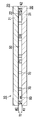
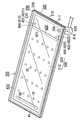
- the glass panel unit 10 of this embodiment is a vacuum heat insulating glass unit.
- the vacuum heat insulating glass unit is a kind of multilayer glass panel including at least a pair of glass panels, and has a vacuum space 50 between the pair of glass panels.
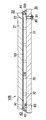
- a part (lower left) of the first glass panel 20 is broken and drawn so that the internal structure can be easily understood. Note that the top, bottom, left, and right directions in the figure are based on directions in which numbers can be read correctly.
- the glass panel unit 10 includes a first glass panel 20, a second glass panel 30, a seal 40, a vacuum space 50, and a spacer 70.
- the second glass panel 30 is disposed so as to face the first glass panel 20.
- the seal 40 joins the first glass panel 20 and the second glass panel 30 in a frame shape in an airtight manner.
- the vacuum space 50 is surrounded by the first glass panel 20, the second glass panel 30, and the seal 40.
- the spacer 70 is disposed between the first glass panel 20 and the second glass panel 30. The height of the spacer 70 is smaller than the height of the seal 40 between the first glass panel 20 and the second glass panel 30.
- the glass panel unit 10 can be formed with a structure that is strong against external impacts because the height of the spacer 70 is smaller than the height of the seal 40. Therefore, the glass panel unit 10 excellent in strength is obtained.
- the first glass panel 20 includes a main body 21 that defines a planar shape of the first glass panel 20 and a coating 22.
- the main body 21 has a rectangular shape and has a first surface (outer surface; upper surface in FIG. 1) and a second surface (inner surface; lower surface in FIG. 1) parallel to each other in the thickness direction. Both the first surface and the second surface of the main body 21 are flat surfaces.
- the material of the main body 21 of the first glass panel 20 is, for example, soda lime glass, high strain point glass, chemically tempered glass, alkali-free glass, quartz glass, neoceram, or physically tempered glass. Note that the first glass panel 20 may not have the coating 22.
- the first glass panel 20 may be configured only from the main body 21.
- the coating 22 is formed on the second surface of the main body 21.
- the coating 22 is preferably an infrared reflecting film.
- the coating 22 is not limited to the infrared reflecting film, and may be a film having desired physical characteristics.
- the second glass panel 30 includes a main body 31 that defines the planar shape of the second glass panel 30.
- the main body 31 is rectangular and has a first surface (inner surface; upper surface in FIG. 1) and a second surface (outer surface; lower surface in FIG. 1) in the thickness direction parallel to each other. Both the first surface and the second surface of the main body 31 are flat surfaces.
- the material of the main body 31 of the second glass panel 30 is, for example, soda lime glass, high strain point glass, chemically tempered glass, alkali-free glass, quartz glass, neoceram, or physically tempered glass.
- the material of the main body 31 may be the same as the material of the main body 21.
- the planar shape of the main body 31 is the same as that of the main body 21. That is, the planar shape of the second glass panel 30 is the same as that of the first glass panel 20.
- the second glass panel 30 is composed only of the main body 31. That is, the main body 31 itself is the second glass panel 30.
- the second glass panel 30 may have a coating.
- the coating can be formed on the first surface of the body 31. This coating may be the same as the coating 22 of the first glass panel 20.
- the first glass panel 20 and the second glass panel 30 are arranged so that the second surface of the main body 21 and the first surface of the main body 31 are parallel to and opposed to each other. That is, the first surface of the main body 21 is directed to the outside of the glass panel unit 10, and the second surface of the main body 21 is directed to the inside of the glass panel unit 10. Further, the first surface of the main body 31 is directed to the inside of the glass panel unit 10, and the second surface of the main body 31 is directed to the outside of the glass panel unit 10.
- the first glass panel 20 and the second glass panel 30 may have curved surfaces that are slightly bent, rather than having a completely flat surface.
- the thickness of the first glass panel 20 is not particularly limited, but is, for example, in the range of 1 to 10 mm.
- the thickness of the second glass panel 30 is not particularly limited, but is, for example, in the range of 1 to 10 mm.
- the first glass panel 20 and the second glass panel 30 may have the same thickness or different thicknesses. When the thickness of the 1st glass panel 20 and the 2nd glass panel 30 is the same, formation of the glass panel unit 10 becomes easy.
- the outer edges of the first glass panel 20 and the second glass panel 30 are aligned in plan view. Therefore, the appearance of the glass panel unit 10 is improved. Moreover, handling of the glass panel unit 10 becomes easy. Moreover, the applicability of the glass panel unit 10 spreads. Moreover, the intensity
- the plan view means that the glass panel unit 10 is viewed in the thickness direction.
- the thickness direction of the glass panel unit 10 is equal to the height direction of the spacer 70.
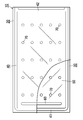
- the glass panel unit 10 further includes a gas adsorber 60.
- the gas adsorber 60 is disposed in the vacuum space 50.
- the gas adsorber 60 has a long shape.
- the gas adsorber 60 is formed along the width direction of the second glass panel 30 on the second end side in the length direction of the second glass panel 30 (left end side in FIG. 2). That is, the gas adsorber 60 is disposed at the end of the vacuum space 50. In this way, the gas adsorber 60 can be made inconspicuous. Further, if the gas adsorber 60 is directly arranged on the glass panel, the gas adsorber 60 can be easily arranged. Note that the gas adsorber 60 can be provided at any location in the vacuum space 50.
- the gas adsorber 60 is used for adsorbing unnecessary gas (residual gas or the like).
- the unnecessary gas is, for example, a gas released when the seal 40 is formed.
- unnecessary gas is gas that enters the inside through the gap of the seal 40. When the gas increases, the degree of vacuum decreases and the heat insulating property may decrease.
- the gas adsorber 60 has a getter.
- a getter is a material that has the property of adsorbing molecules smaller than a predetermined size.
- the getter is, for example, an evaporation type getter.
- the evaporative getter is, for example, a zeolite or an ion exchanged zeolite.
- the seal 40 completely surrounds the vacuum space 50 and airtightly joins the first glass panel 20 and the second glass panel 30.
- the seal 40 is disposed between the first glass panel 20 and the second glass panel 30.
- the seal 40 has a rectangular frame shape.
- the degree of vacuum in the vacuum space 50 is a predetermined value or less.
- the predetermined value is, for example, 0.1 Pa.
- the vacuum space 50 can be formed by exhaust. Exhaust can be performed by forming a hole for exhausting at least one of the first glass panel 20, the second glass panel 30, and the seal 40, and sucking the gas inside. However, it is preferable that exhaust air to be described later is performed and no exhaust port exists in both the first glass panel 20 and the second glass panel 30. Thereby, the glass panel unit 10 with a good appearance can be obtained. In FIG. 1, the 1st glass panel 20 and the 2nd glass panel 30 do not have an exhaust port.
- Vacuum can be formed in the vacuum space 50 by exhausting while heating. Vacuum is enhanced by heating. Further, the seal 40 can be formed by heating. The heating temperature for forming the vacuum may be 300 ° C. or higher. Thereby, the vacuum property is further improved. A specific method for forming the vacuum space 50 will be described later.
- the seal 40 is formed with a thermal adhesive.
- the thermal adhesive is, for example, a glass frit.
- the glass frit is, for example, a low melting point glass frit.
- the low melting point glass frit is, for example, a bismuth glass frit, a lead glass frit, or a vanadium glass frit.
- the seal 40 may be formed of a plurality of thermal adhesives as will be described later.
- the seal 40 has a predetermined height.
- the height of the seal 40 is indicated by a symbol H2 in FIG.
- the height H ⁇ b> 2 of the seal 40 defines the distance T ⁇ b> 2 between the first glass panel 20 and the second glass panel 30 at the end of the glass panel unit 10.
- the seal 40 may have a height H2 in the range of 10 to 1000 ⁇ m.
- the seal 40 may protrude from between the first glass panel 20 and the second glass panel 30 to the outside.
- the seal 40 may be present on one or both sides of the side surface of the first glass panel 20 and the side surface of the second glass panel 30.
- the protruding seal 40 may have a length in the thickness direction of the glass panel unit 10 larger than the distance between the first glass panel 20 and the second glass panel 30. Therefore, the height H2 of the seal 40 is defined as the height (distance) between the first glass panel and the second glass panel.
- the outer edge of the seal 40 may be aligned with the outer edges of the first glass panel 20 and the second glass panel 30. Furthermore, the end surface of the seal 40 may be flush with the end surfaces of the first glass panel 20 and the second glass panel 30.
- the side surface of the glass panel unit 10 can be a flat surface without a step. A flat side surface can be obtained by cutting at a portion of the seal 40 in the cutting of a glass substrate (material of a glass panel) described later. When the assembly 110 is cut so as to divide the seal 40, a flat side surface can be formed (the position of the cutting line 900 is changed in FIG. 8 described later).
- the flat side surface can be obtained by polishing the side portion of the glass panel unit 10 after cutting the glass substrate.
- the seal 40 may be polished, the glass panel may be polished, or both of them may be polished.
- a flat side surface can be obtained by cutting the glass panel along the outer edge of the seal 40.
- the seal 40 includes a material that adjusts the distance between the first glass panel 20 and the second glass panel 30.
- the space between the 1st glass panel 20 and the 2nd glass panel 30 can be formed reliably.
- the material that adjusts the distance between the first glass panel 20 and the second glass panel 30 include particles and wires. The particles can be easily mixed with the thermal adhesive to form a distance between the first glass panel 20 and the second glass panel 30.
- the seal 40 may include particles for forming a distance between the first glass panel 20 and the second glass panel 30.
- the particles may have the property that they are not deformed by heat as the thermal adhesive changes to the seal 40. Since the particles are sandwiched between the two glass panels, when the two glass panels are bonded, the gap between the two glass panels does not become smaller than the particle diameter. Therefore, the height of the seal 40 can be ensured without being crushed.
- metal particles, high-melting glass particles, or the like can be used.
- the particles may be beads. Depending on the size of the particles, the height H2 of the seal 40 can be adjusted.
- the glass panel unit 10 includes a plurality of spacers 70.
- the plurality of spacers 70 are used to maintain the distance between the first glass panel 20 and the second glass panel 30 at a predetermined distance.
- the space between the first glass panel 20 and the second glass panel 30 is more reliably secured by the spacer 70.
- the number of the spacers 70 may be one, in order to ensure the thickness between glass panels, two or more are preferable. When the plurality of spacers 70 are used, the strength of the glass panel unit 10 is increased.
- the plurality of spacers 70 are arranged in the vacuum space 50. Specifically, the plurality of spacers 70 are arranged at intersections of virtual rectangular grids. For example, the interval between the plurality of spacers 70 is in the range of 1 to 10 cm, specifically 2 cm. However, the size of the spacers 70, the number of the spacers 70, the interval between the spacers 70, and the arrangement pattern of the spacers 70 can be selected as appropriate.
- the spacer 70 is formed using a transparent material. Thereby, the spacer 70 becomes inconspicuous. However, each spacer 70 may be formed using an opaque material as long as it is sufficiently small.
- the material of the spacer 70 is selected so that the spacer 70 is not deformed in a first melting process, an exhaust process, and a second melting process, which will be described later.
- the material of the spacer 70 is selected to have a softening point (softening temperature) that is higher than the first softening point of the first thermal adhesive and the second softening point of the second thermal adhesive.
- the spacer 70 may be formed of a polymer. Thereby, elasticity is provided and the impact resistance of the glass panel unit 10 can be improved.
- the spacer 70 may be formed of a polymer film.
- the spacer 70 may be formed of a laminate of two or more polymer films, or may be formed of one polymer film. When the spacer 70 is formed of a laminate of two or more polymer films, the polymer film may be bonded with an adhesive.
- the laminated body may be formed in advance before bonding the two glass panels. In the laminated body, the height of the spacer 70 can be easily adjusted. The laminated body can be cut into an appropriate size and used as the spacer 70.
- polyimide is preferable. Polyimide has high strength and heat resistance. A polyimide having a benzoxazole structure is particularly preferable.
- the spacer 70 has a cylindrical shape.
- the spacer 70 has a predetermined height.
- the height of the spacer 70 is indicated by a symbol H1 in FIG.
- the spacer 70 may have a diameter in the range of 0.1 to 10 mm and a height H1 in the range of 10 to 1000 ⁇ m.
- Each spacer 70 may have a desired shape such as a prismatic shape or a spherical shape.
- the height H ⁇ b> 1 of the spacer 70 defines a distance T ⁇ b> 1 between the first glass panel 20 and the second glass panel 30 in the central portion of the glass panel unit 10.
- the distance T1 is the thickness of the vacuum space 50.
- the thickness of the vacuum space 50 may be in the range of 10 to 1000 ⁇ m, for example.
- a relationship of H1 ⁇ H2 is established between the height H1 of the spacer 70 and the height H2 of the seal 40.
- the height H1 of the spacer 70 and the height H2 of the seal 40 are small (both can be 1000 ⁇ m or less), which makes it difficult to understand the difference. Therefore, to the naked eye, the glass panel unit 10 appears that H1 and H2 are substantially the same. However, when measured precisely, the height relationship is H1 ⁇ H2.
- the gap between the first glass panel 20 and the second glass panel 30 is drawn at the end of the glass panel unit 10.
- the glass panel unit 10 may have a shape in which one or both of the first glass panel 20 and the second glass panel 30 are recessed at the center.
- One or both of the first glass panel 20 and the second glass panel 30 may be warped toward the inside.
- One or both of the first glass panel 20 and the second glass panel 30 may be warped.
- One or both of the first glass panel 20 and the second glass panel 30 may be bent.
- One or both of the first glass panel 20 and the second glass panel 30 may be curved inward.
- the height H1 of the spacer 70 and the height H2 of the seal 40 mean the height after the glass panel unit 10 is formed. These do not mean the height before the glass panel unit 10 is formed or during the formation of the glass panel unit 10. This is because the height of the spacer 70 and the height of the seal 40 can be changed in the formation of the glass panel unit 10.
- the difference between the height H1 of the spacer 70 and the height H2 of the seal 40 is not particularly limited. For example, it is preferably larger than 1 ⁇ m, more preferably larger than 5 ⁇ m, and further larger than 10 ⁇ m. preferable.
- the height H1 of the spacer 70 may be 95% or less of the height H2 of the seal 40, or 90% or less of the height H2 of the seal 40.
- the difference between the height H1 of the spacer 70 and the height H2 of the seal 40 is too large, the stable vacuum space 50 may not be formed, so that the vacuum space 50 is appropriately formed so as to be stably formed.
- Can be set to The difference between the height H1 of the spacer 70 and the height H2 of the seal 40 is not particularly limited.
- the height H1 of the spacer 70 may be 70% or more of the height H2 of the seal 40, or 80% or more of the height H2 of the seal 40.
- the distance between the first glass panel 20 and the second glass panel 30 can change.
- sticker 40 is T2.
- the distance between the first glass panel 20 and the second glass panel 30 at the center of the glass panel unit 10, that is, at the center of the vacuum space 50 is T1.
- a relationship of T1 ⁇ T2 can be established between the distance T1 and the distance T2.
- the distance between the first glass panel 20 and the second glass panel 30 in the center is smaller than the distance between the first glass panel 20 and the third glass panel 30 in the vicinity of the seal 40. May be.
- the distance between the first glass panel 20 and the second glass panel 30 may be smaller toward the center.
- the distance between the first glass panel 20 and the second glass panel 30 in the vacuum space 50 is defined as the thickness of the vacuum space 50.
- the plurality of spacers 70 may have the same height or different heights.
- the glass panel unit 10 can be easily manufactured.
- the height of the plurality of spacers 70 may change.
- the plurality of spacers 70 can vary in the manufacture of the glass panel unit 10. This is because the spacer 70 is sandwiched between two glass panels.
- the height of the plurality of spacers 70 before the formation of the glass panel unit 10 may be the same, and the height of the plurality of spacers 70 after the formation of the glass panel unit 10 may be different. In that case, manufacture of the glass panel unit 10 becomes easy. Or the height of the several spacer 70 before formation of the glass panel unit 10 may differ.
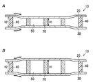
- FIG. 3A and FIG. 3B are schematic explanatory views for explaining the operation of the glass panel unit.
- 3A shows a case where the height H1 of the spacer 70 is smaller than the height H2 of the seal 40.
- FIG. 3B shows a case where the height H ⁇ b> 1 of the spacer 70 is larger than the height H ⁇ b> 2 of the seal 40. That is, FIG. 3A shows the relationship of H1 ⁇ H2, and FIG. 3B does not satisfy this relationship.
- these heights are exaggerated (deformed) so that the relationship between the heights of the spacers 70 and the seals 40 can be easily understood.
- the glass panel unit 10 is simplified and described.
- the two glass panels are compressed and bonded.
- the strength is increased.
- the strength in the direction perpendicular to the surface of the glass panel unit 10 can be improved.
- force is applied in the direction in which the two glass panels approach.
- FIG. 3B in the relationship of H1> H2, the two glass panels are pulled and bonded.
- force is applied to the two glass panels in a direction away from each other. In this case, since the two glass panels are slightly deformed in the direction away from each other, the strength may be reduced.
- the increase / decrease in the strength of the glass panel unit 10 described in FIGS. 3A and 3B is presumed to be caused by the stress applied to the glass panel.
- the stress applied to the glass panel is directed inward (arrow). Therefore, the structure made of two glass panels has high strength.
- the stress applied to the glass panel is directed outward (arrow). Therefore, the structure made of two glass panels tends to be low in strength. Thus, it is considered that the difference in stress affects the strength of the glass panel unit 10.
- the increase or decrease in the strength of the glass panel unit 10 described with reference to FIGS. 3A and 3B is presumed to contribute to the formation process of the seal 40. That is, when the seal 40 is formed from the thermal adhesive, the thermal adhesive is compressed in the case of FIG. 3A, but the thermal adhesive is not compressed in the case of FIG. 3B. Thermal adhesive affects the adhesion of the glass panel. Therefore, in the adhesive force of two glass panels, it is thought that FIG. 3B tends to be weaker than FIG. 3A. Therefore, in FIG. 3B, the strength of the glass panel unit 10 can be lowered. This is confirmed from the fact that, in the falling ball test of the glass panel unit 10, the glass breaks violently in the vicinity of the seal 40 apart from the portion hit by the ball.
- FIGS. 4 to 10 are production examples of the glass panel unit 10.
- the glass panel unit 10 shown in FIGS. 1, 2, and 3A can be manufactured by the method shown in FIGS. 4 to 10, the glass panel unit 10 having no exhaust port is manufactured.
- the glass panel unit 10 first obtains the temporary assembly 100 as shown in FIGS. 4 to 6, and then obtains the assembly 110 shown in FIGS. 7 to 9 by a predetermined process. Thereafter, as shown in FIG. 10, a glass panel unit 10 can be obtained by cutting a part from the assembly 110.
- the manufacturing method of the glass panel unit 10 has a preparation process, an assembly process, a sealing process, and a removal process. Note that the preparation step may be omitted.
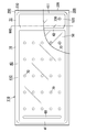
- the preparation step is a step of preparing the first glass substrate 200, the second glass substrate 300, the frame 410, the partition 420, the gas adsorbent 60, and the plurality of spacers 70.
- the internal space 500, the air passage 600, and the exhaust port 700 can be formed by the preparation process.
- the first glass substrate 200 is a substrate used for the first glass panel 20.
- the first glass substrate 200 includes a glass plate 210 that defines a planar shape of the first glass substrate 200 and a coating 220.
- the glass plate 210 is a rectangular flat plate and has a first surface and a second surface in the thickness direction parallel to each other.
- the coating 220 is formed on the second surface of the glass plate 210.
- the glass plate 210 constitutes the main body 21 of the first glass panel 20.
- the first surface of the glass plate 210 corresponds to the first surface of the main body 21, and the second surface of the glass plate 210 corresponds to the second surface of the main body 21.
- the coating 220 constitutes the coating 22 of the first glass panel 20.
- the coating 220 may not be present.
- the second glass substrate 300 is a substrate used for the second glass panel 30.
- the second glass substrate 300 includes a glass plate 310 that defines the planar shape of the second glass substrate 300.
- the glass plate 310 is a rectangular flat plate and has a first surface and a second surface in the thickness direction parallel to each other.
- the second glass substrate 300 constitutes the main body 31 of the second glass panel 30.
- the first surface of the glass plate 310 corresponds to the first surface of the main body 31, and the second surface of the glass plate 310 corresponds to the second surface of the main body 31.
- the planar shape and planar size of the glass plate 310 are the same as those of the glass plate 210. That is, the planar shape of the second glass substrate 300 is the same as that of the first glass substrate 200.
- the thickness of the glass plate 310 is the same as that of the glass plate 210.
- the second glass substrate 300 is composed only of the glass plate 310. That is, the glass plate 310 is the second glass substrate 300 itself.
- the second glass substrate 300 is disposed so as to face the first glass substrate 200. Specifically, the first glass substrate 200 and the second glass substrate 300 are arranged such that the second surface of the glass plate 210 and the first surface of the glass plate 310 are parallel to and face each other.
- the frame body 410 is disposed between the first glass substrate 200 and the second glass substrate 300, and joins the first glass substrate 200 and the second glass substrate 300 in an airtight manner. As a result, as shown in FIG. 6, an internal space 500 surrounded by the frame body 410, the first glass substrate 200, and the second glass substrate 300 is formed.
- the frame body 410 is formed of a thermal adhesive (a first thermal adhesive having a first softening point).
- the first thermal adhesive is, for example, a glass frit.
- the glass frit is, for example, a low melting point glass frit.
- the low melting point glass frit is, for example, a bismuth glass frit, a lead glass frit, or a vanadium glass frit.
- the first thermal adhesive preferably includes particles for ensuring a gap between the two glass panels. The particles can define the height of the frame 410. The particles can define the height of the seal 40.
- the frame 410 has a rectangular frame shape.
- the planar shape of the frame 410 is the same as that of the glass plates 210 and 310, but the planar size of the frame 410 is smaller than the glass plates 210 and 310.
- the frame body 410 is formed along the outer periphery of the second glass substrate 300. That is, the frame 410 is formed so as to surround almost all the region on the second glass substrate 300.
- the partition 420 is disposed in the internal space 500. As shown in FIG. 6, the partition 420 partitions the internal space 500 into an exhaust space 510 and a ventilation space 520.
- the exhaust space 510 is a space to be exhausted later, and the ventilation space 520 is a space used for exhausting the exhaust space 510.
- the partition 420 has a first end side in the length direction (left-right direction in FIG. 4) of the second glass substrate 300 from the center of the second glass substrate 300 so that the exhaust space 510 is larger than the ventilation space 520. 4 on the right end side).
- the partition 420 includes a wall portion 421 and a pair of blocking portions 422 (a first blocking portion 4221 and a second blocking portion 4222).
- the wall portion 421 is formed along the width direction of the second glass substrate 300.
- the width direction means a direction along the short side of the rectangular temporary assembly 100 in FIG. However, both ends in the length direction of the wall portion 421 are not in contact with the frame body 410.
- the pair of blocking portions 422 extend from both ends in the length direction of the wall portion 421 to the first end side in the length direction of the second glass substrate 300.
- the partition 420 is formed of a thermal adhesive (second thermal adhesive having a second softening point).
- the second thermal adhesive is, for example, a glass frit.
- the glass frit is, for example, a low melting point glass frit.
- the low melting point glass frit is, for example, a bismuth glass frit, a lead glass frit, or a vanadium glass frit.
- the second thermal adhesive is the same as the first thermal adhesive, and the second softening point and the first softening point are equal.
- the second thermal adhesive preferably contains particles for ensuring a gap between the two glass panels.
- the particles can define the height of the partition 420.
- the particles can define the height of the seal 40.
- the gas adsorber 60 is disposed in the exhaust space 510. Specifically, the gas adsorber 60 is disposed at the end of the exhaust space 510. Further, the gas adsorber 60 is located away from the partition 420 and the ventilation path 600. Therefore, it is possible to reduce the possibility that the gas adsorber 60 hinders exhaust when exhausting the exhaust space 510.
- the plurality of spacers 70 are the same as those described with reference to FIGS.
- the spacer 70 may be composed of a laminate of films. As described above, the spacer 70 is obtained, for example, by bonding two or more polymer films with an adhesive and then cutting the film. A step of forming the spacer 70 may be added to the preparation step. As shown in FIG. 4, the plurality of spacers 70 can be arranged at predetermined intervals in the vertical and horizontal directions.
- the spacer 70 as a member before being incorporated into the glass panel unit 10 and the spacer 70 after the glass panel unit 10 is formed may have different heights.
- the spacer 70 can be compressed in the height direction by being sandwiched between two glass panels. Therefore, for example, the height of the spacer 70 may be equal to or higher than the height of the frame 410 before the glass panel unit 10 is formed. However, it is more preferable that the height of the spacer 70 before the formation of the glass panel unit 10 is smaller than the height of the frame body 410. As a result, the spacer 70 is less likely to be crushed, and even if the spacer 70 is crushed, the crushing is less noticeable. Moreover, the intensity
- the height of the partition 420 is the same as the height of the frame 410, and the height of the spacer 70 before the formation of the glass panel unit 10 is more preferably smaller than the height of the partition 420.
- the ventilation path 600 connects the exhaust space 510 and the ventilation space 520 in the internal space 500.
- the ventilation path 600 includes a first ventilation path 610 and a second ventilation path 620.
- the first air passage 610 is a space formed between the first blocking portion 4221 and the portion of the frame 410 that faces the first blocking portion 4221.
- the second ventilation path 620 is a space formed between the second blocking portion 4222 and the portion of the frame 410 that faces the second blocking portion 4222.
- the exhaust port 700 is a hole that connects the ventilation space 520 and the external space.
- the exhaust port 700 is used to exhaust the exhaust space 510 through the ventilation space 520 and the ventilation path 600. Therefore, the ventilation path 600, the ventilation space 520, and the exhaust port 700 constitute an exhaust path for exhausting the exhaust space 510.
- the exhaust port 700 is formed in the second glass substrate 300 so as to connect the ventilation space 520 and the external space. Specifically, the exhaust port 700 is located at a corner portion of the second glass substrate 300.
- the preparation process is performed by the members as described above.
- the preparation step includes first to sixth steps. Note that the order of the second to sixth steps may be changed as appropriate.
- the first step is a step of forming the first glass substrate 200 and the second glass substrate 300 (substrate forming step). For example, in the first step, the first glass substrate 200 and the second glass substrate 300 are produced. In the first step, the first glass substrate 200 and the second glass substrate 300 are cleaned as necessary.
- the second step is a step of forming the exhaust port 700.
- the exhaust port 700 is formed in the second glass substrate 300.
- the second glass substrate 300 is cleaned as necessary.
- the exhaust port 700 may be provided in the first glass substrate 200.
- the third step is a step of forming the frame body 410 and the partition 420 (sealing material forming step).
- the material of the frame 410 (first thermal adhesive) and the material of the partition 420 (second thermal adhesive) are used for the second glass substrate 300 (first surface of the glass plate 310) using a dispenser or the like. ) Apply on top.
- the material of the frame 410 and the material of the partition 420 are dried and temporarily fired.
- coated is heated at 480 degreeC for 20 minutes.
- the first glass substrate 200 may be heated together with the second glass substrate 300. That is, the first glass substrate 200 may be heated under the same conditions as the second glass substrate 300 (20 minutes at 480 ° C.). Thereby, the difference of the curvature of the 1st glass substrate 200 and the 2nd glass substrate 300 can be reduced.
- the fourth step is a step of installing the spacer 70 (spacer installation step).
- a plurality of spacers 70 are formed in advance, and the plurality of spacers 70 are installed at predetermined positions on the second glass substrate 300 using a chip mounter or the like.
- the plurality of spacers 70 may be formed using a known thin film forming technique.
- the spacer 70 can be formed by applying a resin composition on the second glass substrate 300.
- the fifth step is a step of forming the gas adsorbent 60 (gas adsorbent forming step).
- the gas adsorber 60 is formed by applying a solution in which getter powder is dispersed to a predetermined position of the second glass substrate 300 and drying the solution.
- the frame 410, the partition 420, the ventilation path 600, the exhaust port 700, the gas adsorbent 60, and the plurality of spacers 70 as shown in FIG. 4 are formed. Two glass substrates 300 are obtained.
- the sixth step is a step of arranging the first glass substrate 200 and the second glass substrate 300 (arrangement step).
- the first glass substrate 200 and the second glass substrate 300 are arranged such that the second surface of the glass plate 210 and the first surface of the glass plate 310 are parallel to and face each other.
- FIG. 5 shows a state in which the first glass substrate 200 is overlaid on the second glass substrate 300.
- each member (frame body 410, partition 420, etc.) is arranged on the second glass substrate 300, but each member may be arranged on the first glass substrate 200.
- the assembly process is a process of preparing the temporary assembly 100. Specifically, in the assembly process, the first glass substrate 200 and the second glass substrate 300 are joined to prepare the temporary assembly 100. That is, the assembly process is a process (first melting process) in which the first glass substrate 200 and the second glass substrate 300 are hermetically bonded by the frame body 41.
- the first glass substrate 200 and the second glass substrate 300 are hermetically bonded by once melting the first thermal adhesive at a predetermined temperature (first melting temperature) equal to or higher than the first softening point. .
- the first glass substrate 200 and the second glass substrate 300 are hermetically bonded by the frame body 410.
- the first glass substrate 200 and the second glass substrate 300 are placed in a melting furnace and heated at a first melting temperature for a predetermined time (first melting time).
- the first glass substrate 200 and the second glass substrate 300 are hermetically bonded by the thermal adhesive of the frame 410, but the air passage 600 is blocked by the partition 420. It is set so that there is no. That is, the lower limit of the first melting temperature is the first softening point, but the upper limit of the first melting temperature is set so that the air passage 600 is not blocked by the partition 420. For example, when the first softening point and the second softening point are 434 ° C., the first melting temperature is set to 440 ° C.
- the first melting time is, for example, 10 minutes.
- gas is released from the frame 410, but this gas may be adsorbed by the gas adsorber 60.
- the temporary assembly 100 shown in FIG. 6 is obtained by the assembly process (first melting process) described above.
- the temporary assembly 100 includes a first glass substrate 200, a second glass substrate 300, a frame body 410, an internal space 500, a partition 420, an air passage 600, an exhaust port 700, a gas adsorber 60, A plurality of spacers 70.
- the sealing step is a step of obtaining the assembly 110 by performing the predetermined processing on the temporary assembly 100.
- the sealing process includes an exhaust process and a melting process (second melting process). That is, the exhaust process and the second melting process correspond to the predetermined process.
- the exhaust process is a process of exhausting the exhaust space 510 at a predetermined temperature (exhaust temperature) through the ventilation path 600, the ventilation space 520, and the exhaust port 700 to form the vacuum space 50.
- a predetermined temperature exhaust temperature
- a vacuum property increases.
- Exhaust is performed using, for example, a vacuum pump.
- the vacuum pump is connected to the temporary assembly 100 by an exhaust pipe 810 and a seal head 820.
- the exhaust pipe 810 is joined to the second glass substrate 300 so that the inside of the exhaust pipe 810 and the exhaust port 700 communicate with each other.
- a seal head 820 is attached to the exhaust pipe 810, whereby the suction port of the vacuum pump is connected to the exhaust port 700.
- the first melting step, the exhausting step, and the second melting step are performed while the first glass substrate 200 and the second glass substrate 300 are placed in the melting furnace.
- the second glass substrate 300 is provided with a frame body 410, a partition 420, an air passage 600, an exhaust port 700, a gas adsorber 60, and a plurality of spacers 70.
- the exhaust pipe 810 is joined to the second glass substrate 300 at least before the first melting step.
- the exhaust space 510 is exhausted through the ventilation path 600, the ventilation space 520, and the exhaust port 700 for a predetermined time (exhaust time) at a predetermined exhaust temperature.
- the exhaust temperature is set higher than the activation temperature of the getter of the gas adsorber 60 (for example, 350 ° C.) and lower than the first softening point and the second softening point (for example, 434 ° C.).
- the exhaust temperature is preferably 300 ° C. or higher.
- the exhaust temperature is 390 ° C. In this way, the frame body 410 and the partition 420 are not deformed. Further, the getter of the gas adsorber 60 is activated, and molecules (gas) adsorbed by the getter are released from the getter.
- the exhaust time is set so that a vacuum space 50 having a desired degree of vacuum (for example, a degree of vacuum of 0.1 Pa or less) is obtained.
- the exhaust time is set to 120 minutes.
- the second melting step is a step of forming the seal 40 that surrounds the vacuum space 50 by deforming the partition 420 to form the partition wall 42 that closes the ventilation path 600.
- the partition wall 42 is formed by deforming the partition 420 by once melting the second thermal adhesive at a predetermined temperature (second melting temperature) equal to or higher than the second softening point.
- second melting temperature a predetermined temperature
- the first glass substrate 200 and the second glass substrate 300 are heated for a predetermined time (second melting time) at the second melting temperature in the melting furnace.
- the second melting temperature and the second melting time are set so that the second thermal adhesive is softened and the partition wall 42 that blocks the air passage 600 is formed.
- the lower limit of the second melting temperature is the second softening point (434 ° C.).
- the second melting step aims to deform the partition 420, and therefore the second melting temperature is higher than the first melting temperature (440 ° C.).
- the second melting temperature is set to 460 ° C.
- the second melting time is, for example, 30 minutes.
- the vacuum space 50 is separated from the ventilation space 520. Therefore, the vacuum space 50 cannot be exhausted with the vacuum pump.
- the frame body 410 and the partition wall 42 are heated, and thus gas may be released from the frame body 410 and the partition wall 42.
- the gas released from the frame body 410 and the partition wall 42 is adsorbed by the gas adsorber 60 in the vacuum space 50. Therefore, the vacuum degree of the vacuum space 50 is prevented from deteriorating. That is, it is prevented that the heat insulation of the glass panel unit 10 deteriorates.
- the gas adsorber 60 can sufficiently adsorb the gas released from the frame body 410 and the partition wall 42 in the second melting step. That is, it is possible to prevent the gas adsorber 60 from sufficiently adsorbing the gas released from the frame body 410 and the partition wall 42 and deteriorating the vacuum degree of the vacuum space 50.
- the exhaust space 510 is exhausted through the vent path 600, the vent space 520, and the exhaust port 700 continuously from the exhaust step. That is, in the second melting step, the partition wall 42 that blocks the air passage 600 by deforming the partition 420 while exhausting the exhaust space 510 through the air passage 600, the air space 520, and the exhaust port 700 at the second melting temperature. Form. This further prevents the vacuum degree of the vacuum space 50 from being deteriorated during the second melting step. However, in the second melting step, it is not always necessary to exhaust the exhaust space 510 through the vent path 600, the vent space 520, and the exhaust port 700.
- the exhaust space 510 is evacuated to the vacuum space 50 through the ventilation path 600, the ventilation space 520, and the exhaust port 700 at a predetermined temperature (exhaust temperature).
- the exhaust temperature is higher than the activation temperature of the getter of the gas adsorber 60.
- the partition 420 is deformed to form the partition wall 42 that closes the ventilation path 600, thereby forming the seal 40 surrounding the vacuum space 50 (see FIG. 8). Since the partition 420 contains the second thermal adhesive, the partition 420 is deformed by once melting the second thermal adhesive at a predetermined temperature (second melting temperature) that is equal to or higher than the second softening point. Can be formed. The first melting temperature is lower than the second melting temperature. Thereby, when joining the 1st glass substrate 200 and the 2nd glass substrate 300 with the frame 410, it can prevent that the partition 420 deform
- the partition 420 may be formed of a material that is more deformable when melted than the frame body 410.
- the partition 420 is modified such that the first blocking part 4221 closes the first ventilation path 610 and the second blocking part 4222 blocks the second ventilation path 620.
- the partition wall 42 obtained by deforming the partition 420 in this way separates (vacually) the vacuum space 50 from the ventilation space 520.
- the partition (second portion) 42 and the portion (first portion) 41 corresponding to the vacuum space 50 in the frame 410 constitute the seal 40 surrounding the vacuum space 50.
- the vacuum space 50 is formed by exhausting the exhaust space 510 through the ventilation space 520 and the exhaust port 700. Since the vacuum space 50 is completely sealed by the first glass substrate 200, the second glass substrate 300, and the seal 40, the vacuum space 50 is separated from the ventilation space 520 and the exhaust port 700.
- the seal 40 has a first portion 41 and a second portion 42.
- the first portion 41 is a portion corresponding to the vacuum space 50 in the frame 410. That is, the first portion 41 is a portion facing the vacuum space 50 in the frame body 410.
- the first portion 41 is substantially U-shaped and constitutes three sides of the four sides of the seal 40.
- the second portion 42 is a partition wall obtained by deforming the partition 420.
- the second portion 42 is I-shaped and constitutes the remaining one of the four sides of the seal 40.
- the spacer 70 secures a space between the first glass substrate 200 and the second glass substrate 300.
- the first glass panel 20 and the second glass panel 30 are bonded together while the seal 40 is compressed.
- the two glass panels can be bonded with high strength. In particular, the strength in the vicinity of the seal 40 is improved.
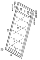
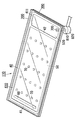
- the assembly 110 shown in FIGS. 7 to 9 is obtained by the sealing process described above.
- the assembly 110 includes a first glass substrate 200, a second glass substrate 300, a seal 40, a vacuum space 50, a ventilation space 520, a gas adsorber 60, and a plurality of spacers 70.
- a part (lower right) of the first glass substrate 200 is broken and drawn so that the internal structure can be easily understood.
- the removal step is a step of obtaining the glass panel unit 10 that is a portion having the vacuum space 50 by removing the portion 11 having the ventilation space 520 from the assembly 110.
- the assembly 110 taken out from the melting furnace is cut along a cutting line 900, and a predetermined portion (glass panel unit) 10 having a vacuum space 50, and a ventilation space. And a portion (unnecessary portion) 11 having 520.
- the unnecessary portion 11 mainly includes a portion 230 corresponding to the ventilation space 520 in the first glass substrate 200, a portion 320 corresponding to the ventilation space 520 in the second glass substrate 300, and a ventilation space in the frame 410. And a portion 411 corresponding to 520. Considering the manufacturing cost of the glass panel unit 10, it is preferable that the unnecessary portion 11 is small.
- FIG. 10 shows a state where the unnecessary portion 11 is removed from the assembly 110.
- Cutting is performed by an appropriate cutting device.
- the cutting device include a scriber and a laser. If the 1st glass substrate 200 and the 2nd glass substrate 300 are cut
- the shape of the cutting line 900 is determined by the shape of the glass panel unit 10. Since the glass panel unit 10 is rectangular, the cutting line 900 is a straight line along the length direction of the wall 42.
- the first glass panel 20 is a portion corresponding to the vacuum space 50 in the first glass substrate 200.
- the second glass panel 30 is a portion corresponding to the vacuum space 50 in the second glass substrate 300.
- the exhaust port 700 for forming the vacuum space 50 exists in the part 320 corresponding to the ventilation space 520 in the second glass substrate 300, and the exhaust pipe 810 is connected to the part 320. Therefore, the second glass panel 30 does not have the exhaust port 700.
- the glass panel unit (10) has a rectangular shape, but the glass panel unit (10) may have a desired shape such as a circular shape or a polygonal shape. That is, the first glass panel (20), the second glass panel (30), and the seal (40) may have a desired shape such as a circular shape or a polygonal shape instead of a rectangular shape.
- each shape of a 1st glass substrate (200), a 2nd glass substrate (300), a frame (410), and a partition (42) is not limited to the shape of the said embodiment, Desired shape What is necessary is just a shape which can obtain a glass panel unit (10).
- size of a glass panel unit (10) are determined according to the use of a glass panel unit (10).
- first surface and the second surface of the main body (21) of the first glass panel (20) are not limited to planes.
- neither the first surface nor the second surface of the main body (31) of the second glass panel (30) is limited to a flat surface.
- the main body (21) of the first glass panel (20) and the main body (31) of the second glass panel (30) may not have the same planar shape and planar size. Moreover, the main body (21) and the main body (31) may not have the same thickness. Moreover, the main body (21) and the main body (31) may not be formed of the same material. Similarly, the glass plate (210) of the first glass substrate (200) and the glass plate (310) of the second glass substrate (300) may not have the same planar shape and planar size. Moreover, the glass plate (210) and the glass plate (310) do not need to have the same thickness. The glass plate (210) and the glass plate (310) may not be formed of the same material.
- the seal (40) may not have the same planar shape as the first glass panel (20) and the second glass panel (30).
- the frame (410) may not have the same planar shape as the first glass substrate (200) and the second glass substrate (300).
- the first glass panel (20) may further include a coating having desired physical properties and formed on the second plane of the main body (21).
- the first glass panel (20) may not include the coating (22). That is, the 1st glass panel (20) may be comprised only with the main body (21).
- the second glass panel (30) may further include a coating having desired physical characteristics.
- the coating only needs to include at least one of thin films formed on the first plane and the second plane of the main body (31), for example.
- the coating is, for example, a film that reflects light of a specific wavelength (infrared reflective film, ultraviolet reflective film).
- the frame (410) is formed of the first thermal adhesive.
- the frame (410) may include other elements such as a core material in addition to the first thermal adhesive. That is, the frame (410) only needs to contain the first thermal adhesive.
- the frame (410) is formed so that the substantially all area
- the frame (410) only needs to be formed so as to surround a predetermined region on the second glass substrate (300). That is, the frame (410) does not need to be formed so as to surround almost the entire region of the second glass substrate (300).
- the assembly (110) may have two or more frames (410). That is, the assembly (110) may have two or more internal spaces (500). In this case, two or more glass panel units (10) can be obtained from one assembly (110).
- the partition (420) is formed of the second thermal adhesive.
- the partition (420) may include other elements such as a core material in addition to the second thermal adhesive. That is, the partition (420) only needs to contain the second thermal adhesive.
- the both ends of the partition (420) are not connected with the frame (410).
- the clearance gap between the both ends of a partition (420) and a frame (410) is a ventilation path (610,620).
- only one of the both ends of the partition (420) may not be connected to the frame (410). In this case, one air passage (between the partition (420) and the frame (410) is provided. 600) is formed. Or the both ends of the partition (420) may be connected with the frame (410).
- the ventilation path (600) may be a through hole formed in the partition (420).
- the air passage (600) may be a gap between the partition (420) and the first glass substrate (200).
- the partition (420) may be formed of two or more partitions arranged at intervals. In this case, the ventilation path (600) may be a gap between two or more partitions.
- the internal space (500) is partitioned into one exhaust space (510) and one ventilation space (520).
- the internal space (500) may be partitioned into one or more exhaust spaces (510) and one or more ventilation spaces (520).
- two or more glass panel units (10) can be obtained from one assembly (110).
- the second thermal adhesive is the same as the first thermal adhesive, and the second softening point and the first softening point are equal.
- the second thermal adhesive may be a material different from the first thermal adhesive.
- the second thermal adhesive may have a second softening point different from the first softening point of the first thermal adhesive.
- the second softening point is preferably higher than the first softening point.
- the first melting temperature can be set to be equal to or higher than the first softening point and lower than the second softening point. By doing so, it is possible to prevent the partition (420) from being deformed in the first melting step.
- first adhesive and the second thermal adhesive are not limited to glass frit, and may be, for example, a low melting point metal or a hot melt adhesive.
- a melting furnace is used for heating the frame (410), the gas adsorber (60), and the partition (420).
- the heating can be performed by an appropriate heating means.
- the heating means is, for example, a laser or a heat transfer plate connected to a heat source.
- the air passage (600) includes two air passages (610, 620). However, the air passage (600) may include only one air passage, or three or more air passages (600, 620). You may be comprised with the ventilation path. Moreover, the shape of the ventilation path (600) is not specifically limited.
- the exhaust port (700) is formed in the second glass substrate (300).
- the exhaust port (700) may be formed in the glass plate (210) of the first glass substrate (200), or may be formed in the frame (410). In short, the exhaust port (700) should just be formed in the unnecessary part (11).
- the getter of the gas adsorbent (60) is an evaporative getter, but the getter may be a non-evaporable getter.
- the non-evaporable getter reaches a predetermined temperature (activation temperature) or higher, the adsorbed ability is recovered by allowing the adsorbed molecules to enter the inside.
- activation temperature a predetermined temperature
- it does not release adsorbed molecules, so if non-evaporable getters adsorb more than a certain amount of molecules, the adsorption capacity is restored even if heated above the activation temperature. No longer.
- the gas adsorbent (60) is elongated, but may be other shapes. Further, the gas adsorber (60) does not necessarily have to be at the end of the vacuum space (50).
- the gas adsorber (60) is a liquid containing getter powder (for example, a dispersion obtained by dispersing getter powder in the liquid, or dissolving the getter powder in the liquid. The solution obtained in this manner is applied.
- the gas adsorber (60) may include a substrate and a getter fixed to the substrate. Such a gas adsorber (60) can be obtained by immersing the substrate in a liquid containing getter powder and drying it.
- the substrate may have a desired shape, for example, a long rectangular shape.
- the gas adsorbent (60) may be a film formed entirely or partially on the surface (first surface) of the glass plate (310) of the second glass substrate (300). Such a gas adsorbent (60) can be obtained by coating the surface (first surface) of the glass plate (310) of the second glass substrate (300) with a liquid containing getter powder.
- the gas adsorber (60) may be included in the spacer (70).
- the spacer (70) is formed of a material including a getter, the spacer (70) including the gas adsorbent (60) can be obtained.
- getters may be included in an adhesive that adheres the polymer films.
- the gas adsorber (60) may be a solid formed by a getter. Such a gas adsorber (60) is relatively large and may not be disposed between the first glass substrate (200) and the second glass substrate (300). In this case, a recess may be formed in the glass plate (310) of the second glass substrate (300), and the gas adsorber (60) may be disposed in this recess.
- the gas adsorber (60) may be arranged in advance in the package so that the getter does not adsorb molecules. In this case, after the second melting step, the package is broken and the gas adsorber (60) is exposed to the vacuum space (50).
- the glass panel unit (10) includes the gas adsorber (60), but the glass panel unit (10) may not include the gas adsorber (60).
- the glass panel unit (10) includes a plurality of spacers (70), but the glass panel unit (10) may include a single spacer (70).
- the glass panel unit (10) having no exhaust port is formed by removing the unnecessary portion (11).
- the glass panel unit (10) has the exhaust port. You may do it.
- an exhaust port may be provided in at least any one of a 1st glass panel (20) and a 2nd glass panel (30). In order to maintain the vacuum of the vacuum space (50), the exhaust port is closed.
- the exhaust port can be closed by a cap material.
- the glass panel unit (10) does not have an exhaust port.
- FIG. 11 shows a modification of the glass panel unit (glass panel unit 10A).
- the glass panel unit 10 ⁇ / b> A has an exhaust port 700 in the second glass panel 30.
- the exhaust port 700 is closed by a sealing portion 81.
- the sealing part 81 is formed from the exhaust pipe 810.
- Sealing portion 81 can be formed by, for example, thermal welding of glass constituting exhaust pipe 810.
- a cap 80 is disposed outside the sealing portion 81.
- the cap 80 covers the sealing portion 81. Since the cap 80 covers the sealing portion 81, the exhaust port 700 can be closed high. Further, the cap 80 can suppress damage at the exhaust port 700 portion.
- the glass panel unit 10A is the same as the glass panel unit 10 of FIGS.
- the same components as those in the glass panel unit 10 in FIGS. 1 and 2 are denoted by the same reference numerals, and the descriptions given in FIGS. 1 and 2 can be applied to these components as appropriate.
- the glass panel unit 10 ⁇ / b> A can be manufactured according to the method for manufacturing the temporary assembly 100. Since it is not necessary to remove the portion having the exhaust port 700, the glass panel unit 10A can be easily manufactured.
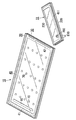
- FIG. 12 shows a modification of the glass panel unit (glass panel unit 10B).
- the outer edges in the plan view of the first glass panel 20 and the second glass panel 30 are not aligned.
- One of the two glass panels (first glass panel 20) is smaller than the other (second glass panel 30).
- the seal 40 protrudes from between the first glass panel 20 and the second glass panel 30 to the outside.
- the height H ⁇ b> 2 of the seal 40 is defined as the distance of the portion of the seal 40 between the first glass panel 20 and the second glass panel 30.
- the glass panel unit 10B is the same as the glass panel unit 10A of FIG. 11 except that the structure of the end is different.
- the same components as those of the glass panel unit 10 of FIGS. 1 and 2 and the glass panel unit 10A of FIG. 11 are denoted by the same reference numerals, and those configurations are appropriately performed in FIGS. The explanation can be applied.
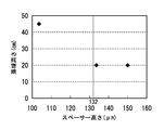
- Example 2 About the glass panel unit, the difference in the physical property by the difference in the height of a spacer was tested.
- a laminate of a polyimide film having a benzoxazole structure was used.
- the height of the spacer was adjusted by varying the thickness of the polyimide film and the number of laminated layers.
- As the polyimide film Toyobo "Zenomax" (registered trademark) was used.
- the height of the seal was adjusted by the particle size. Particles having a particle size of 132 ⁇ m were used. Therefore, the height of the seal is 132 ⁇ m.
- the diameter of the spacer was 500 ⁇ m.
- FIG. 13 is a graph showing the results of the falling ball test of the glass panel unit.
- the falling ball test is an index of impact strength, and is an average height (falling ball height, unit: cm) in which a 225 g sphere was dropped on the glass panel unit and the surface of the glass panel unit was damaged.
- the height of the spacer and the seal is the height after the glass panel unit is formed.
Abstract
Priority Applications (7)
| Application Number | Priority Date | Filing Date | Title |
|---|---|---|---|
| US15/529,325 US10060179B2 (en) | 2014-11-27 | 2015-11-27 | Glass panel unit |
| PL15862666T PL3225602T3 (pl) | 2014-11-27 | 2015-11-27 | Szyba zespolona |
| EP15862666.3A EP3225602B1 (fr) | 2014-11-27 | 2015-11-27 | Unité de panneau en verre |
| JP2016561256A JP6528335B2 (ja) | 2014-11-27 | 2015-11-27 | ガラスパネルユニット |
| CN201580063725.8A CN107001131B (zh) | 2014-11-27 | 2015-11-27 | 玻璃面板单元 |
| DK15862666.3T DK3225602T3 (da) | 2014-11-27 | 2015-11-27 | Glaspanelenhed |
| ES15862666T ES2848303T3 (es) | 2014-11-27 | 2015-11-27 | Unidad de paneles de vidrio |
Applications Claiming Priority (2)
| Application Number | Priority Date | Filing Date | Title |
|---|---|---|---|
| JP2014-240578 | 2014-11-27 | ||
| JP2014240578 | 2014-11-27 |
Publications (1)
| Publication Number | Publication Date |
|---|---|
| WO2016084384A1 true WO2016084384A1 (fr) | 2016-06-02 |
Family
ID=56073972
Family Applications (1)
| Application Number | Title | Priority Date | Filing Date |
|---|---|---|---|
| PCT/JP2015/005909 WO2016084384A1 (fr) | 2014-11-27 | 2015-11-27 | Unité de panneau en verre |
Country Status (9)
| Country | Link |
|---|---|
| US (1) | US10060179B2 (fr) |
| EP (1) | EP3225602B1 (fr) |
| JP (1) | JP6528335B2 (fr) |
| CN (1) | CN107001131B (fr) |
| DK (1) | DK3225602T3 (fr) |
| ES (1) | ES2848303T3 (fr) |
| HU (1) | HUE053486T2 (fr) |
| PL (1) | PL3225602T3 (fr) |
| WO (1) | WO2016084384A1 (fr) |
Cited By (4)
| Publication number | Priority date | Publication date | Assignee | Title |
|---|---|---|---|---|
| TWI630184B (zh) * | 2016-07-21 | 2018-07-21 | 松下知識產權經營股份有限公司 | 玻璃平板單元用的玻璃平板之製造方法及製造裝置 |
| JPWO2018062140A1 (ja) * | 2016-09-30 | 2019-07-25 | パナソニックIpマネジメント株式会社 | ガラスパネルユニット、ガラス窓およびガラスパネルユニットの製造方法 |
| WO2019230218A1 (fr) * | 2018-05-31 | 2019-12-05 | パナソニックIpマネジメント株式会社 | Procédé de fabrication d'une unité panneau en verre |
| US20220090438A1 (en) * | 2018-09-05 | 2022-03-24 | Nippon Sheet Glass Company, Limited | Vacuum glass and method for manufacturing same |
Families Citing this family (4)
| Publication number | Priority date | Publication date | Assignee | Title |
|---|---|---|---|---|
| JP6455791B2 (ja) * | 2014-09-30 | 2019-01-23 | パナソニックIpマネジメント株式会社 | ガラスパネルユニット及びその検査方法 |
| EP3816128B1 (fr) * | 2018-06-28 | 2022-03-09 | Panasonic Intellectual Property Management Co., Ltd. | Procédé de fourniture de piliers, procédé de fabrication d'unité de panneau de verre, et dispositif de fourniture de piliers |
| AU2019375590B2 (en) * | 2018-11-08 | 2022-10-13 | Lg Electronics Inc. | Panel assembly, refrigerator, and home appliances |
| DE102019210574A1 (de) * | 2019-07-17 | 2021-01-21 | Schott Ag | Tür für ein Gefrier- oder Kühlmöbel |
Citations (2)
| Publication number | Priority date | Publication date | Assignee | Title |
|---|---|---|---|---|
| WO2013139281A1 (fr) * | 2012-03-21 | 2013-09-26 | Dai Changhong | Vitre renfermant de l'air à basse pression ou du vide à bords scellés dotée d'un cadre en forme de barre et d'une rainure |
| WO2013172034A1 (fr) * | 2012-05-18 | 2013-11-21 | パナソニック株式会社 | Procédé de fabrication de double vitrage |
Family Cites Families (5)
| Publication number | Priority date | Publication date | Assignee | Title |
|---|---|---|---|---|
| US6558494B1 (en) * | 1999-09-24 | 2003-05-06 | Guardian Industries Corp. | Vacuum IG window unit with edge seal at least partially diffused at temper and completed via microwave curing, and corresponding method of making the same |
| JP4049607B2 (ja) | 2002-04-11 | 2008-02-20 | 日本板硝子株式会社 | ガラスパネルの製造方法とその方法で製造されたガラスパネル |
| US8202587B2 (en) | 2009-05-01 | 2012-06-19 | Guardian Industries Corp. | Edge profiles for vacuum insulated glass (VIG) units, and/or VIG unit including the same |
| CN104136390B (zh) * | 2012-03-07 | 2017-08-22 | 松下知识产权经营株式会社 | 多层玻璃 |
| CN102701575B (zh) * | 2012-03-21 | 2015-07-01 | 戴长虹 | 凸面真空玻璃、平板真空玻璃及其制备方法 |
-
2015
- 2015-11-27 PL PL15862666T patent/PL3225602T3/pl unknown
- 2015-11-27 EP EP15862666.3A patent/EP3225602B1/fr active Active
- 2015-11-27 HU HUE15862666A patent/HUE053486T2/hu unknown
- 2015-11-27 US US15/529,325 patent/US10060179B2/en active Active
- 2015-11-27 ES ES15862666T patent/ES2848303T3/es active Active
- 2015-11-27 WO PCT/JP2015/005909 patent/WO2016084384A1/fr active Application Filing
- 2015-11-27 JP JP2016561256A patent/JP6528335B2/ja active Active
- 2015-11-27 CN CN201580063725.8A patent/CN107001131B/zh active Active
- 2015-11-27 DK DK15862666.3T patent/DK3225602T3/da active
Patent Citations (2)
| Publication number | Priority date | Publication date | Assignee | Title |
|---|---|---|---|---|
| WO2013139281A1 (fr) * | 2012-03-21 | 2013-09-26 | Dai Changhong | Vitre renfermant de l'air à basse pression ou du vide à bords scellés dotée d'un cadre en forme de barre et d'une rainure |
| WO2013172034A1 (fr) * | 2012-05-18 | 2013-11-21 | パナソニック株式会社 | Procédé de fabrication de double vitrage |
Cited By (7)
| Publication number | Priority date | Publication date | Assignee | Title |
|---|---|---|---|---|
| TWI630184B (zh) * | 2016-07-21 | 2018-07-21 | 松下知識產權經營股份有限公司 | 玻璃平板單元用的玻璃平板之製造方法及製造裝置 |
| US11236004B2 (en) | 2016-07-21 | 2022-02-01 | Panasonic Intellectual Property Management Co., Ltd. | Manufacturing method and manufacturing apparatus of glass panel for glass panel unit |
| JPWO2018062140A1 (ja) * | 2016-09-30 | 2019-07-25 | パナソニックIpマネジメント株式会社 | ガラスパネルユニット、ガラス窓およびガラスパネルユニットの製造方法 |
| WO2019230218A1 (fr) * | 2018-05-31 | 2019-12-05 | パナソニックIpマネジメント株式会社 | Procédé de fabrication d'une unité panneau en verre |
| JPWO2019230218A1 (ja) * | 2018-05-31 | 2021-07-08 | パナソニックIpマネジメント株式会社 | ガラスパネルユニットの製造方法 |
| JP7178594B2 (ja) | 2018-05-31 | 2022-11-28 | パナソニックIpマネジメント株式会社 | ガラスパネルユニットの製造方法 |
| US20220090438A1 (en) * | 2018-09-05 | 2022-03-24 | Nippon Sheet Glass Company, Limited | Vacuum glass and method for manufacturing same |
Also Published As
| Publication number | Publication date |
|---|---|
| EP3225602B1 (fr) | 2020-11-25 |
| US10060179B2 (en) | 2018-08-28 |
| JP6528335B2 (ja) | 2019-06-12 |
| EP3225602A1 (fr) | 2017-10-04 |
| DK3225602T3 (da) | 2021-01-18 |
| JPWO2016084384A1 (ja) | 2017-09-28 |
| US20170328124A1 (en) | 2017-11-16 |
| PL3225602T3 (pl) | 2021-06-14 |
| CN107001131B (zh) | 2020-01-17 |
| ES2848303T3 (es) | 2021-08-06 |
| CN107001131A (zh) | 2017-08-01 |
| HUE053486T2 (hu) | 2021-06-28 |
| EP3225602A4 (fr) | 2017-11-29 |
Similar Documents
| Publication | Publication Date | Title |
|---|---|---|
| WO2016084384A1 (fr) | Unité de panneau en verre | |
| WO2016084382A1 (fr) | Unité de panneau en verre | |
| JP6471916B2 (ja) | ガラスパネルユニット、ガラスパネルユニットの仮組立て品、ガラスパネルユニットの組立て品、ガラスパネルユニットの製造方法 | |
| JP2016108799A (ja) | ガラスパネルユニット | |
| JP6455791B2 (ja) | ガラスパネルユニット及びその検査方法 | |
| JP6384799B2 (ja) | ガラスパネルユニット | |
| US10597933B2 (en) | Glass panel unit and windowpane | |
| JP2019178063A (ja) | ガラスパネルユニットの製造方法 | |
| JP6767702B2 (ja) | ガラスパネルユニットおよびガラス窓 | |
| JP6775190B2 (ja) | ガラスパネルユニットおよびガラス窓 | |
| JP6865391B2 (ja) | ガラスパネルユニット、ガラス窓およびガラスパネルユニットの製造方法 | |
| JPWO2017056419A1 (ja) | ガラスパネルユニットの製造方法およびガラス窓の製造方法 | |
| WO2019230218A1 (fr) | Procédé de fabrication d'une unité panneau en verre | |
| US11162297B2 (en) | Glass panel unit assembly, and method for manufacturing glass panel unit | |
| JP6854453B2 (ja) | ガラスパネルユニットの製造方法およびガラス窓の製造方法 | |
| US11230878B2 (en) | Glass panel unit assembly and method for manufacturing glass panel unit | |
| US11428041B2 (en) | Glass panel unit assembly, method for manufacturing glass panel unit, work in progress of glass panel unit, and glass panel unit | |
| JP7038333B2 (ja) | ガラスパネルユニットの製造方法 | |
| WO2019207971A1 (fr) | Unité de panneau en verre, produit semi-fini d'unité de panneau en verre, produit assemblé d'unité de panneau en verre, et procédé de fabrication d'unité de panneau en verre | |
| US20210300822A1 (en) | Glass panel unit and method for manufacturing the glass panel unit |
Legal Events
| Date | Code | Title | Description |
|---|---|---|---|
| 121 | Ep: the epo has been informed by wipo that ep was designated in this application |
Ref document number: 15862666 Country of ref document: EP Kind code of ref document: A1 |
|
| ENP | Entry into the national phase |
Ref document number: 2016561256 Country of ref document: JP Kind code of ref document: A |
|
| REEP | Request for entry into the european phase |
Ref document number: 2015862666 Country of ref document: EP |
|
| WWE | Wipo information: entry into national phase |
Ref document number: 15529325 Country of ref document: US |
|
| NENP | Non-entry into the national phase |
Ref country code: DE |