WO2016079937A1 - 排気浄化システム - Google Patents
排気浄化システム Download PDFInfo
- Publication number
- WO2016079937A1 WO2016079937A1 PCT/JP2015/005514 JP2015005514W WO2016079937A1 WO 2016079937 A1 WO2016079937 A1 WO 2016079937A1 JP 2015005514 W JP2015005514 W JP 2015005514W WO 2016079937 A1 WO2016079937 A1 WO 2016079937A1
- Authority
- WO
- WIPO (PCT)
- Prior art keywords
- solute
- aqueous solution
- exhaust
- urea
- urea aqueous
- Prior art date
- Legal status (The legal status is an assumption and is not a legal conclusion. Google has not performed a legal analysis and makes no representation as to the accuracy of the status listed.)
- Ceased
Links
Images
Classifications
-
- B—PERFORMING OPERATIONS; TRANSPORTING
- B01—PHYSICAL OR CHEMICAL PROCESSES OR APPARATUS IN GENERAL
- B01D—SEPARATION
- B01D53/00—Separation of gases or vapours; Recovering vapours of volatile solvents from gases; Chemical or biological purification of waste gases, e.g. engine exhaust gases, smoke, fumes, flue gases, aerosols
- B01D53/34—Chemical or biological purification of waste gases
- B01D53/92—Chemical or biological purification of waste gases of engine exhaust gases
- B01D53/94—Chemical or biological purification of waste gases of engine exhaust gases by catalytic processes
-
- F—MECHANICAL ENGINEERING; LIGHTING; HEATING; WEAPONS; BLASTING
- F01—MACHINES OR ENGINES IN GENERAL; ENGINE PLANTS IN GENERAL; STEAM ENGINES
- F01N—GAS-FLOW SILENCERS OR EXHAUST APPARATUS FOR MACHINES OR ENGINES IN GENERAL; GAS-FLOW SILENCERS OR EXHAUST APPARATUS FOR INTERNAL-COMBUSTION ENGINES
- F01N3/00—Exhaust or silencing apparatus having means for purifying, rendering innocuous, or otherwise treating exhaust
- F01N3/08—Exhaust or silencing apparatus having means for purifying, rendering innocuous, or otherwise treating exhaust for rendering innocuous
-
- Y—GENERAL TAGGING OF NEW TECHNOLOGICAL DEVELOPMENTS; GENERAL TAGGING OF CROSS-SECTIONAL TECHNOLOGIES SPANNING OVER SEVERAL SECTIONS OF THE IPC; TECHNICAL SUBJECTS COVERED BY FORMER USPC CROSS-REFERENCE ART COLLECTIONS [XRACs] AND DIGESTS
- Y02—TECHNOLOGIES OR APPLICATIONS FOR MITIGATION OR ADAPTATION AGAINST CLIMATE CHANGE
- Y02A—TECHNOLOGIES FOR ADAPTATION TO CLIMATE CHANGE
- Y02A50/00—TECHNOLOGIES FOR ADAPTATION TO CLIMATE CHANGE in human health protection, e.g. against extreme weather
- Y02A50/20—Air quality improvement or preservation, e.g. vehicle emission control or emission reduction by using catalytic converters
-
- Y—GENERAL TAGGING OF NEW TECHNOLOGICAL DEVELOPMENTS; GENERAL TAGGING OF CROSS-SECTIONAL TECHNOLOGIES SPANNING OVER SEVERAL SECTIONS OF THE IPC; TECHNICAL SUBJECTS COVERED BY FORMER USPC CROSS-REFERENCE ART COLLECTIONS [XRACs] AND DIGESTS
- Y02—TECHNOLOGIES OR APPLICATIONS FOR MITIGATION OR ADAPTATION AGAINST CLIMATE CHANGE
- Y02T—CLIMATE CHANGE MITIGATION TECHNOLOGIES RELATED TO TRANSPORTATION
- Y02T10/00—Road transport of goods or passengers
- Y02T10/10—Internal combustion engine [ICE] based vehicles
- Y02T10/12—Improving ICE efficiencies
Definitions
- the present disclosure relates to an exhaust purification system that purifies exhaust.
- an exhaust purification system (urea SCR system) having a selective reduction catalyst (SCR catalyst) using urea is known as a technique for reducing nitrogen oxide (NOx) discharged from an internal combustion engine of a vehicle (for example, see Patent Document 1).
- an SCR catalyst that selectively reduces NOx by the action of a reducing agent is disposed in an exhaust passage of an internal combustion engine, and the exhaust flow upstream of the SCR catalyst is disposed upstream.
- the urea aqueous solution serving as the reducing agent is jetted.
- a 32.5% urea aqueous solution having the lowest freezing temperature ( ⁇ 11 ° C.) is used as the urea aqueous solution used in this exhaust purification system.
- the temperature around the urea water tank that stores the urea aqueous solution may drop to the freezing point (-11 ° C.) of the urea aqueous solution. .
- the urea aqueous solution may be locally frozen or totally frozen in the urea water tank, and it is necessary to take measures against freezing at low temperatures.
- a heater is disposed in the urea water tank or in the urea water pipe connected to the urea water tank.
- the freezing of the urea aqueous solution is suppressed by operating the heater when the temperature of the urea aqueous solution is lowered to the freezing point. For this reason, when the freezing point of the urea aqueous solution is high, the frequency of operating the heater increases, and the power consumption by the heater increases. As a result, the fuel consumption of the vehicle deteriorates.
- an object of the present disclosure is to provide an exhaust purification system capable of improving the antifreeze performance of a reducing solution containing a reducing agent that reduces nitrogen oxides contained in exhaust gas.
- an exhaust purification system that purifies exhaust discharged from an energy conversion unit that generates exhaust including nitrogen oxides when energy conversion is performed based on fuel oxidation in the presence of nitrogen and oxygen includes: And a catalyst that promotes a reduction reaction of nitrogen oxides and a reduction that is supplied from the storage unit.
- the storage unit stores a reducing solution that reduces the nitrogen oxides contained in the exhaust gas.
- a supply unit that supplies the working solution to the catalyst.
- the reducing solution has a reducing agent that reduces nitrogen oxides contained in the exhaust, a solute different from the reducing agent, and a solvent capable of dissolving the reducing agent and the solute.
- the first portion that is selectively close to the solid-liquid interface of the solvent and the first portion that is connected to the first portion and has a sparse relationship with the solvent It is composed of molecules having two sites.
- the first part of the solute is adsorbed in close proximity to the solid-liquid interface of the solvent.
- the progress of freezing can be suppressed.
- the second portion having a sparse relationship with the solvent prevents the solvent from approaching the solid-liquid interface, the progress of freezing can be further suppressed. Therefore, the antifreeze performance of the reducing solution can be improved.
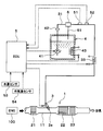
- FIG. 1 is a schematic diagram illustrating an overall configuration of a urea SCR system according to an embodiment of the present disclosure.
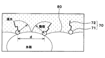
- FIG. 2 is an explanatory diagram for explaining the configuration of the urea aqueous solution in the embodiment of the present disclosure.
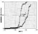
- FIG. 3 is a characteristic diagram showing the relationship between the temperature of the urea aqueous solution and the number of frozen parts.
- an exhaust passage 11 through which exhaust gas discharged from the internal combustion engine 100 flows is connected to an internal combustion engine (ENG) 100 of the vehicle.
- the internal combustion engine 100 is an energy conversion unit that converts fuel energy into motive power, which is another form of energy, based on fuel oxidation in air, that is, in the presence of nitrogen and oxygen.
- the internal combustion engine 100 generates exhaust gas containing nitrogen oxides when performing energy conversion.
- a diesel engine is employed as the internal combustion engine 100.
- the exhaust discharged from the internal combustion engine 100 passes through the exhaust aftertreatment device 1 installed in the exhaust passage 11 and is then released to the outside of the vehicle.
- the exhaust aftertreatment device 1 is a first oxidation catalyst 21, a selective reduction catalyst (SCR catalyst) 22, a second oxidation catalyst in order from the upstream side of the exhaust flow as a catalyst for purifying NOx (nitrogen oxide) in the exhaust. 23.
- the first oxidation catalyst 21 converts nitrogen monoxide (NO) in the exhaust gas to nitrogen dioxide (NO 2 ) to increase the NO 2 ratio in NOx and facilitate the NOx reduction reaction. At the same time, the first oxidation catalyst 21 also functions to oxidize hydrocarbon (HC) and carbon monoxide (CO) in the exhaust gas.
- NO nitrogen monoxide
- HC hydrocarbon
- CO carbon monoxide
- SCR catalyst 22 selectively reduces and purifies NOx by the action of a reducing agent. That is, the SCR catalyst 22 is a catalyst that promotes the reduction reaction of NOx. Between the first oxidation catalyst 21 and the SCR catalyst 22, an addition valve 3 is provided as a supply unit that supplies a reducing agent to the SCR catalyst 22.
- urea which is a precursor of ammonia, is used as the reducing agent, and is injected and supplied from the addition valve 3 into the exhaust passage 11 in a urea aqueous solution that is easy to handle.
- the urea aqueous solution of the present embodiment is a mixed solution having urea as a reducing agent and water as a solvent capable of dissolving urea, and corresponds to the reducing solution of the present disclosure.
- the second oxidation catalyst 23 is for suppressing the ammonia generated from urea without being released without reacting with NOx, and oxidizes, decomposes and detoxifies the ammonia that has passed through the SCR catalyst 22.
- the SCR catalyst 22 and the second oxidation catalyst 23 are provided integrally.
- the urea aqueous solution supplied to the addition valve 3 is stored in a tank 4 as a storage part.
- the tank 4 is a sealed container having a predetermined capacity.
- a pump 41 that sucks out the urea aqueous solution stored in the tank 4 is provided inside the tank 4 .
- a urea aqueous solution supply path 31 that connects the pump 41 and the addition valve 3.
- the urea aqueous solution supply path 31 is provided with a filter 42 for removing foreign matters mixed in the urea aqueous solution.
- the pump 41 When the pump 41 is driven, the urea aqueous solution stored in the tank 4 is sucked out and is pumped to the addition valve 3 via the filter 42.
- the pump 41 is an electric pump whose rotation speed (urea aqueous solution supply amount) is controlled by a control signal output from the control device 5.
- the addition valve 3 may have a known air assist type injection valve structure, for example.
- the air assist type the urea aqueous solution supply path 31 is connected to the addition valve 3, and an air supply path (not shown) provided with an air compressor is connected, and the nozzle portion 3 a is opened and closed by an actuator to exhaust the exhaust flow path 11.
- a urea aqueous solution is injected into the air together with assisting air.
- the addition valve 3 is attached to the wall of the exhaust passage 11 so as to be inclined as shown. At this time, the injection direction of the nozzle portion 3 a protruding into the exhaust flow path 11 is parallel to the exhaust flow, and the urea aqueous solution is evenly supplied to the entire inlet side end surface of the SCR catalyst 22.
- the urea aqueous solution supply path 31 is provided with a pressure regulator 6 having an on-off valve for adjusting the supply pressure.
- the pressure regulator 6 is configured such that when the set pressure is exceeded, the on-off valve is opened so that excess urea aqueous solution returns to the tank 4 from a return path 61 connected to the upper portion of the tank 4.
- a tank heater 43 for heating the urea aqueous solution in the tank 4 is provided.
- the urea aqueous solution supply path 31 is provided with a supply path heater 33 that heats the urea aqueous solution flowing through the urea aqueous solution supply path 31.
- the tank heater 43 and the supply path heater 33 are also collectively referred to as heaters 33 and 43.
- the heaters 33 and 43 electric heaters that heat the urea aqueous solution by supplying electricity are employed.
- the heaters 33 and 43 are controlled in operation (heat generation amount) by a control signal output from the control device 5.
- the control device 5 is composed of a well-known microcomputer including a CPU, ROM, RAM, etc. and its peripheral circuits. Then, various operations and processes are performed based on the control program stored in the ROM to control the operation of various devices connected to the output side.
- a pressure sensor 51 that detects the pressure of the urea aqueous solution flowing through the urea aqueous solution supply path 31
- a temperature sensor 52 that detects the temperature of the urea aqueous solution flowing through the urea aqueous solution supply path 31, and the internal combustion engine 100.
- a sensor group such as a water temperature sensor 53 for detecting the cooling water temperature of the cooling water flowing out from the outside, and an outside air temperature sensor 54 for detecting the outside air temperature is connected.
- the urea aqueous solution of this embodiment includes urea, which is a reducing agent that reduces nitrogen oxides contained in exhaust gas, a solute 70 different from urea (reducing agent), and water that is a solvent capable of dissolving urea (reducing agent). It is comprised by the solution which has.
- the solute 70 contained in the urea aqueous solution is composed of molecules including a head 71 as a first part and a tail 72 as a second part.
- the head 71 is a part that is selectively close to the solid-liquid interface 80 of water as a solvent when the temperature of the urea aqueous solution becomes equal to or lower than a predetermined reference temperature.
- the tail 72 is a part connected to the head 71 and having a sparse relationship with water as a solvent.
- one of the head 71 and the tail 72 constituting the molecule of the solute 70 has hydrophilicity, and the other has lipophilicity (hydrophobic).
- the head 71 has hydrophilicity and the tail 72 has lipophilicity.
- any one of a quaternary ammonium group, a sulfo group, an ester group, a carboxyl group, and a hydroxyl group is employed.
- the tail 72 of the solute 70 one having a plurality of carbons as a main chain and 4 or less hydrophilic groups bonded to each carbon is employed.
- solute 70 a compound in which the head 71 is a trimethylammonium group and the tail 72 is a linear hydrocarbon group having 16 or less carbon atoms is employed as the solute 70 of the present embodiment. More specifically, hexadecyltrimethylammonium bromide (hereinafter referred to as C 16 TAB) is employed as the solute 70.
- C 16 TAB hexadecyltrimethylammonium bromide
- the solute 70 of this embodiment includes polyoxyethylene (10) octylphenyl ether (Triton (registered trademark) X-100), polyoxyethylene (25) octyldodecyl ether (emulgen ( (Registered trademark) 2025G), polyoxyethylene sorbitan oleate (Tween (registered trademark) 80), stearic acid PEG-150, myristyl sulfobetaine, sodium cholate may be employed.
- polyoxyethylene (10) octylphenyl ether Triton (registered trademark) X-100
- polyoxyethylene (25) octyldodecyl ether emulgen ( (Registered trademark) 2025G)
- polyoxyethylene sorbitan oleate Teween (registered trademark) 80)
- stearic acid PEG-150 stearic acid PEG-150
- myristyl sulfobetaine sodium
- a solution obtained by adding 0.10% of C 16 TAB to the current 32.5% urea aqueous solution (AdBlue (registered trademark)) is referred to as a urea aqueous solution according to the present embodiment.
- the inventor conducted a freezing experiment using the urea aqueous solution according to the present embodiment. Specifically, a metallic plate-like member having 36 dimples is prepared, and after the urea aqueous solution according to the present embodiment is injected into each dimple, the temperature of the plate-like member is lowered to obtain a plate-like member. The relationship between the temperature (i.e., the temperature of the urea aqueous solution) and the number of dimples in which the urea aqueous solution was frozen was verified. The results are shown in the white circle plot of FIG.
- the present inventor conducted a freezing experiment similar to the urea aqueous solution according to the above-described embodiment using the current 32.5% urea aqueous solution (AdBlue (registered trademark)) as the urea aqueous solution according to the comparative example. It was. This result is shown in the white square plot of FIG.
- the temperature shown on the horizontal axis in FIG. 3 is the temperature of the plate member, that is, the temperature of the urea aqueous solution.
- the frozen number frequency shown on the vertical axis in FIG. 3 is an index indicating how many dimples out of a total of 36 dimples the urea aqueous solution is frozen. The case where the aqueous solution is frozen is defined as 100%.
- the urea aqueous solution according to this embodiment can lower the freezing temperature by 7 ° C. relative to the urea aqueous solution according to the comparative example.
- the urea concentration (weight percent concentration) of the urea aqueous solution according to the present embodiment is 32.5%, which is the same as the urea concentration of the urea aqueous solution according to the comparative example, the freezing point (freezing temperature) can be lowered. For this reason, since the operating frequency of the heaters 33 and 43 decreases, the power consumption of the heaters 33 and 43 can be reduced by 30%.
- the freezing point of the urea aqueous solution according to the present embodiment is set to -11 ° C. which is the same as the freezing point of the urea aqueous solution according to the comparative example, the urea concentration can be increased by 10%. Therefore, the capacity of the tank 4, the number of refills injecting the urea aqueous solution into the tank 4, and the heat of evaporation required to evaporate the urea aqueous solution when the urea aqueous solution is injected from the addition valve 3 are each reduced by 10%. can do.
- the concentration of the solute 70 contained in the urea aqueous solution is smaller than the saturated dissolution concentration of the solute 70 with respect to water. According to this, it can suppress that the solute 70 recrystallizes and ice grows with the crystal
- the solute 70 different from urea is mixed in the urea aqueous solution.
- the solute 70 includes a head 71 that is selectively close to the solid-liquid interface 80 of water and a tail 72 that is connected to the head 71 and has a hydrophobic property when the temperature of the urea aqueous solution becomes a reference temperature or lower. It is made up of molecules.
- the head 71 of the solute 70 is adsorbed in close proximity to the solid-liquid interface 80 of the water. Since the growth of ice nuclei (solidified nuclei) of water is inhibited by the head 71 adsorbed on the solid-liquid interface 80 of water, the progress of freezing can be suppressed. Furthermore, since the tail 72 having hydrophobicity suppresses water from approaching the solid-liquid interface 80, the progress of freezing can be further suppressed. Therefore, it becomes possible to improve the antifreeze performance of the urea aqueous solution.
- the urea concentration of the urea aqueous solution is equal to the conventional one, the freezing point of the urea aqueous solution can be lowered. Thereby, the power consumption of the heaters 33 and 43 can be reduced.
- At least one of an increase in the urea concentration of the urea aqueous solution and a reduction in the power consumption of the heaters 33 and 43 can be achieved.
- the concentration of C 16 TAB mixed with the urea aqueous solution is 0.1%
- the amount of the solute 70 mixed with the urea aqueous solution is about 1/100 of the conventional amount.
- antifreeze performance can be ensured. For this reason, it can suppress that the composition of exhaust_gas
Landscapes
- Engineering & Computer Science (AREA)
- Chemical & Material Sciences (AREA)
- Combustion & Propulsion (AREA)
- Analytical Chemistry (AREA)
- Biomedical Technology (AREA)
- Environmental & Geological Engineering (AREA)
- Health & Medical Sciences (AREA)
- General Chemical & Material Sciences (AREA)
- Oil, Petroleum & Natural Gas (AREA)
- Chemical Kinetics & Catalysis (AREA)
- Mechanical Engineering (AREA)
- General Engineering & Computer Science (AREA)
- Exhaust Gas After Treatment (AREA)
- Exhaust Gas Treatment By Means Of Catalyst (AREA)
Abstract
エネルギ変換部(100)から排出される排気を浄化する排気浄化システムは、排気に含まれる窒素酸化物を還元する還元用溶液を貯留する貯留部(4)と、排気流路(11)に設けられるとともに、窒素酸化物の還元反応を促進する触媒(22)と、貯留部(4)から供給された還元用溶液を触媒(22)に供給する供給部(3)とを備える。還元用溶液は、排気に含まれる窒素酸化物を還元する還元剤である尿素と、尿素とは異なる溶質(70)と、還元剤および溶質を溶解可能な溶媒とを有しており、溶質(70)は、還元用溶液の温度が予め定めた基準温度以下になった場合に、溶媒の固液界面(80)に選択的に近接する第1部位(71)と、第1部位(71)に接続されるとともに、溶媒に対して疎となる関係を有する第2部位(72)とを有する分子により構成されている。
Description
本出願は、2014年11月20日に出願された日本特許出願番号2014-235512号に基づくもので、ここにその記載内容を援用する。
本開示は、排気を浄化する排気浄化システムに関するものである。
従来、車両の内燃機関から排出される窒素酸化物(NOx)を低減する技術として、尿素を用いた選択的還元触媒(SCR触媒)を有する排気浄化システム(尿素SCRシステム)が知られている(例えば、特許文献1参照)。
この特許文献1に記載のような排気浄化システムは、内燃機関の排気流路に、還元剤の作用でNOxを選択的に還元するSCR触媒が配置されており、SCR触媒の排気流れ上流側に、還元剤となる尿素水溶液が噴射されるように構成されている。この排気浄化システムに用いられる尿素水溶液としては、凍結温度が最も低い(-11℃)、尿素32.5%水溶液が用いられている。
ところが、寒冷地や厳冬期のように使用環境が極低温となる場合には、尿素水溶液を貯留する尿素水タンクの周囲の温度が、尿素水溶液の凝固点(-11℃)まで低下するおそれがある。このため、尿素水タンク内において尿素水溶液が局所的に凍結または全凍結するおそれがあり、低温下での凍結対策が必要となっている。
これに対し、従来の排気浄化システムでは、尿素水タンク内や、尿素水タンクに接続する尿素水配管等にヒータを配設している。これにより、尿素水溶液の凍結を抑制している。
しかしながら、上記従来の技術では、凍結温度が最も低くなる濃度の尿素水溶液を用いているため、尿素水溶液中の尿素濃度をこれ以上増大させることが困難である。すなわち、尿素水溶液中の尿素濃度を増大させると、凝固点が上昇してしまう。
したがって、上記従来の技術では、尿素水溶液中の水の量が多くなるため、尿素水タンクの容量を大きくする、または、尿素水タンクに尿素水溶液を注入するリフィル回数を増加させる必要がある。また、尿素水溶液中の水の量が多いため、SCR触媒の上流側に噴射した際に、尿素水溶液を蒸発させるのに必要な熱量が増大してしまう。
ところで、上記従来の技術では、尿素水溶液の温度が凝固点まで低下した場合にヒータを作動させることで、尿素水溶液の凍結を抑制している。このため、尿素水溶液の凝固点が高いと、ヒータを作動させる頻度が高くなり、ヒータによる電力消費が増大してしまう。その結果、車両の燃費が悪化する。
本開示は上記点に鑑みて、排気に含まれる窒素酸化物を還元する還元剤を含む還元用溶液の不凍性能を向上させることができる排気浄化システムを提供すること目的とする。
本開示の一態様において、窒素および酸素の存在下における燃料酸化に基づいてエネルギ変換する際に窒素酸化物を含む排気を生成するエネルギ変換部から排出される排気を浄化する排気浄化システムは、排気に含まれる窒素酸化物を還元する還元用溶液を貯留する貯留部と、排気が流通する排気流路に設けられるとともに、窒素酸化物の還元反応を促進する触媒と、貯留部から供給された還元用溶液を触媒に供給する供給部とを備える。還元用溶液は、排気に含まれる窒素酸化物を還元する還元剤と、還元剤とは異なる溶質と、還元剤および溶質を溶解可能な溶媒とを有しており、溶質は、還元用溶液の温度が予め定めた基準温度以下になった場合に、溶媒の固液界面に選択的に近接する第1部位と、第1部位に接続されるとともに、溶媒に対して疎となる関係を有する第2部位とを有する分子により構成されている。
これによれば、還元用溶液の温度が低下して基準温度以下になった場合に、溶質の第1部位が溶媒の固液界面に選択的に近接して吸着する。これにより、溶媒の固液界面に吸着した第1部位により、溶媒の凝固核の成長が阻害されるため、凍結の進行を抑制できる。さらに、溶媒に対して疎となる関係を有する第2部位により、溶媒が固液界面に近づくことが抑制されるので、凍結の進行をより抑制できる。したがって、還元用溶液の不凍性能を向上させることが可能となる。
本開示についての上記目的およびその他の目的、特徴や利点は、添付の図面を参照しながら下記の詳細な記述により、より明確になる。その図面は、
図1は、本開示の実施形態に係る尿素SCRシステムの全体構成を示す概略図であり、
図2は、本開示の実施形態における尿素水溶液の構成を説明するための説明図であり、
図3は、尿素水溶液の温度と凍結個数頻度との関係を示す特性図である。
以下、本開示の一実施形態について図に基づいて説明する。本実施形態では、本開示の排気浄化システムを、車両の内燃機関の尿素SCRシステムに適用した例について説明する。
図1に示すように、車両の内燃機関(ENG)100には、内燃機関100から排出される排気が流通する排気流路11が接続されている。内燃機関100は、空気中、すなわち窒素および酸素の存在下における燃料酸化に基づいて、燃料のエネルギを他の形態のエネルギである動力に変換するエネルギ変換部である。内燃機関100は、エネルギ変換を行う際に、窒素酸化物を含む排気を生成する。本実施系形態では、内燃機関100として、ディーゼルエンジンが採用されている。
内燃機関100から排出される排気は、排気流路11に設置した排気後処理装置1を通過した後、車外に放出される。排気後処理装置1は、排気中のNOx(窒素酸化物)を浄化するための触媒として、排気流れ上流側から順に第1酸化触媒21、選択的還元触媒(SCR触媒)22、第2酸化触媒23を有している。
第1酸化触媒21は、排気中の一酸化窒素(NO)を二酸化窒素(NO2)に転換してNOx中のNO2比率を高め、NOx還元反応を容易にする。同時に、第1酸化触媒21は、排気中の炭化水素(HC)および一酸化炭素(CO)を酸化する機能も果たしている。
SCR触媒22は、還元剤の作用でNOxを選択的に還元浄化する。すなわち、SCR触媒22は、NOxの還元反応を促進する触媒である。第1酸化触媒21とSCR触媒22との間には、SCR触媒22に還元剤を供給する供給部としての添加弁3が設けられている。本実施形態では、還元剤としてアンモニアの前駆体である尿素を使用し、取り扱いの容易な尿素水溶液の状態で、添加弁3から排気流路11内に噴射供給する。
本実施形態の尿素水溶液は、還元剤である尿素と、尿素を溶解可能な溶媒である水とを有する混合溶液であり、本開示の還元用溶液に相当している。
第2酸化触媒23は、尿素から生成されるアンモニアがNOxと反応せずに放出されるのを抑制するためのもので、SCR触媒22を通過したアンモニアを酸化、分解して無害化する。本実施形態では、SCR触媒22と第2酸化触媒23とを一体的に設けている。
添加弁3に供給される尿素水溶液は、貯留部としてのタンク4に貯蔵されている。タンク4は、所定容量の密封容器である。
タンク4の内部には、タンク4に貯留された尿素水溶液を吸い出すポンプ41が設けられている。タンク4には、ポンプ41と添加弁3とを接続する尿素水溶液供給路31が接続されている。尿素水溶液供給路31には、尿素水溶液に混ざった異物を取り除くためのフィルタ42が設けられている。
ポンプ41を駆動することで、タンク4内に貯留されている尿素水溶液が吸い出され、フィルタ42を経由して、添加弁3へ圧送される。このポンプ41は、制御装置5から出力される制御信号によって回転数(尿素水溶液供給量)が制御される電動式のポンプである。
添加弁3は、例えば、公知のエアアシスト式の噴射弁構造とすることができる。エアアシスト式では、添加弁3に尿素水溶液供給路31を接続するとともに、エアコンプレッサを設けたエア供給路(図示せず)を接続し、アクチュエータにてノズル部3aを開閉して排気流路11内にアシスト用のエアとともに尿素水溶液を噴射する。
添加弁3は、図示するように、排気流路11の壁部に対して傾斜して取り付けられている。このとき、排気流路11内に突出するノズル部3aの噴射方向が、排気流れと平行な方向となり、尿素水溶液が、SCR触媒22の入口側端面の全面に均等に供給される。
尿素水溶液供給路31には、供給圧力を調整するため開閉弁を備えるプレッシャレギュレータ6が設けられている。プレッシャレギュレータ6は、設定圧を超えると開閉弁が開放されて、タンク4上部に接続されたリターン路61から余剰の尿素水溶液がタンク4に戻るように構成されている。
タンク4の内部には、タンク4内の尿素水溶液を加熱するタンク内ヒータ43が設けられている。また、尿素水溶液供給路31には、尿素水溶液供給路31を流通する尿素水溶液を加熱する供給路ヒータ33が設けられている。以下、タンク内ヒータ43および供給路ヒータ33をまとめてヒータ33、43ともいう。
本実施形態では、ヒータ33、43として、電気が供給されることにより尿素水溶液を加熱する電気ヒータが採用されている。ヒータ33、43は、制御装置5から出力される制御信号によって、その作動(発熱量)が制御される。
制御装置5は、CPU、ROMおよびRAM等を含む周知のマイクロコンピュータとその周辺回路から構成される。そして、このROM内に記憶された制御プログラムに基づいて各種演算、処理を行って、出力側に接続された各種機器の作動を制御する。
制御装置5の出力側には、上述した添加弁3、ポンプ41およびヒータ33、43等が接続されている。
制御装置5の入力側には、尿素水溶液供給路31を流通する尿素水溶液の圧力を検出する圧力センサ51、尿素水溶液供給路31を流通する尿素水溶液の温度を検出する温度センサ52、内燃機関100から流出した冷却水の冷却水温度を検出する水温センサ53、外気温を検出する外気温センサ54等のセンサ群が接続されている。
図1において、添加弁3から排気流路11内に本実施形態の尿素水溶液が噴射されると、以下の式(i)に示すように、噴射された尿素水溶液中の尿素は、排気熱により熱分解されてアンモニア(NH3)が発生する。
(NH2)2CO→NH3+CHNO …(i)
このとき、同時に生成するシアン酸(CHNO)は、以下の式(ii)に示すように、さらに加水分解され、アンモニアと二酸化炭素が発生する。
このとき、同時に生成するシアン酸(CHNO)は、以下の式(ii)に示すように、さらに加水分解され、アンモニアと二酸化炭素が発生する。
CHNO+H2O→NH3+CO2 …(ii)
発生したアンモニアは、以下の式(iii)に示すように、SCR触媒22上でNOxの還元剤として作用し、NOxの還元反応を促進する。
発生したアンモニアは、以下の式(iii)に示すように、SCR触媒22上でNOxの還元剤として作用し、NOxの還元反応を促進する。
NO+NO2+2NH3→2N2+3H2O …(iii)
一方、NOxの還元に寄与せずにSCR触媒22を通過したアンモニアは、以下の式(iv)に示すように、第2酸化触媒23により浄化される。
一方、NOxの還元に寄与せずにSCR触媒22を通過したアンモニアは、以下の式(iv)に示すように、第2酸化触媒23により浄化される。
4NH3+3O2→2N2+6H2O …(iv)
次に、本実施形態に係る尿素SCRシステムで用いられる尿素水溶液について説明する。本実施形態の尿素水溶液は、排気に含まれる窒素酸化物を還元する還元剤である尿素と、尿素(還元剤)とは異なる溶質70と、尿素(還元剤)を溶解可能な溶媒である水とを有する溶液により構成されている。
次に、本実施形態に係る尿素SCRシステムで用いられる尿素水溶液について説明する。本実施形態の尿素水溶液は、排気に含まれる窒素酸化物を還元する還元剤である尿素と、尿素(還元剤)とは異なる溶質70と、尿素(還元剤)を溶解可能な溶媒である水とを有する溶液により構成されている。
図2に示すように、尿素水溶液に含まれる溶質70は、第1部位であるヘッド71と、第2部位であるテール72とを備える分子により構成されている。ヘッド71は、尿素水溶液の温度が予め定めた基準温度以下になった場合に、溶媒である水の固液界面80に選択的に近接する部位である。テール72は、ヘッド71に接続されるとともに、溶媒である水に対して疎となる関係を有する部位である。
また、溶質70の分子を構成するヘッド71およびテール72のうち、一方が親水性を有しており、他方が親油性(疎水性)を有している。本実施形態では、溶質70の分子のうち、ヘッド71が親水性を有しており、テール72が親油性を有している。
本実施形態では、溶質70のヘッド71として、第4級アンモニウム基、スルホ基、エステル基、カルボキシル基およびヒドロキル基のうちのいずれかが採用されている。また、溶質70のテール72として、複数の炭素を主鎖とするとともに、各炭素と結合される親水基が4個以下であるものが採用されている。
具体的には、本実施形態の溶質70として、ヘッド71がトリメチルアンモニウム基であるとともに、テール72が炭素数16以下の直鎖状炭化水素基である化合物を採用している。より具体的には、溶質70として、臭化ヘキサデシルトリメチルアンモニウム(以下、C16TABという)を採用している。
なお、本実施形態の溶質70としては、C16TABの他に、ポリオキシエチレン(10)オクチルフェニルエーテル(Triton(登録商標)X-100)、ポリオキシエチレン(25)オクチルドデシルエーテル(エマルゲン(登録商標)2025G)、オレイン酸ポリオキシエチレンソルビタン(Tween(登録商標)80)、ステアリン酸PEG-150、ミリスチルスルホベタイン、コール酸ナトリウムを採用することができる。
ここで、現行の32.5%尿素水溶液(AdBlue(登録商標))に対して、C16TABを0.10%添加した溶液を、本実施形態に係る尿素水溶液という。本発明者は、本実施形態に係る尿素水溶液を用いて、凍結実験を行った。具体的には、36個のディンプルを有する金属性の板状部材を用意し、各ディンプルに本実施形態に係る尿素水溶液を注入した後、板状部材の温度を低下させていき、板状部材の温度(すなわち尿素水溶液の温度)と尿素水溶液が凍結しているディンプルの個数との関係を検証した。この結果を、図3の白丸プロットに示す。
また、本発明者は、比較例に係る尿素水溶液として、現行の32.5%尿素水溶液(AdBlue(登録商標))を用いて、上述した本実施形態に係る尿素水溶液と同様の凍結実験を行った。この結果を、図3の白四角プロットに示す。
なお、図3の横軸に示す温度とは、板状部材の温度、すなわち尿素水溶液の温度である。また、図3の縦軸に示す凍結個数頻度とは、全部で36個のディンプルのうち、何個のディンプルにおいて、尿素水溶液が凍結しているかを表す指標であり、36個全てのディンプルにおいて尿素水溶液が凍結している場合を100%としている。
図3から明らかなように、本実施形態に係る尿素水溶液は、比較例に係る尿素水溶液に対して、凍結温度を7℃低下させることができる。
したがって、本実施形態に係る尿素水溶液の尿素濃度(重量パーセント濃度)を、比較例に係る尿素水溶液の尿素濃度と同じ32.5%とした場合、凝固点(凍結温度)を低下させることができる。このため、ヒータ33、43の作動頻度が低下するので、ヒータ33、43の消費電力を30%低減することができる。
また、本実施形態に係る尿素水溶液の凝固点を、比較例に係る尿素水溶液の凝固点と同じ-11℃とした場合、尿素濃度を10%増大させることができる。このため、タンク4の容量、タンク4に尿素水溶液を注入するリフィル回数、および、添加弁3から尿素水溶液を噴射した際に尿素水溶液を蒸発させるのに必要な蒸発熱を、それぞれ、10%低減することができる。
ところで、尿素水溶液に含まれる溶質70の濃度は、水に対する溶質70の飽和溶解濃度よりも小さくなっている。これによれば、溶質70が再結晶し、その結晶を核として氷が成長することを抑制できる。さらに、尿素水溶液に含まれる溶質70の濃度を、水に対する溶質70の臨界ミセル濃度以下にすることで、溶質70がミセル化し、そのミセルを核として氷が成長することを抑制できる。
以上説明したように、本実施形態では、尿素水溶液に、尿素と異なる溶質70を混合している。この溶質70は、尿素水溶液の温度が基準温度以下になった場合に、水の固液界面80に選択的に近接するヘッド71と、ヘッド71に接続されるとともに疎水性を有するテール72とを備える分子により構成されている。
これによれば、尿素水溶液の温度が低下して基準温度以下になった場合に、溶質70のヘッド71が水の固液界面80に選択的に近接して吸着する。そして、水の固液界面80に吸着したヘッド71により、水の氷核(凝固核)の成長が阻害されるため、凍結の進行を抑制できる。さらに、疎水性を有するテール72により、水が固液界面80に近づくことが抑制されるので、凍結の進行をより抑制できる。したがって、尿素水溶液の不凍性能を向上させることが可能となる。
このため、尿素水溶液の凝固点を従来と同じ温度に保ちつつ、すなわち従来と同等の不凍性能を確保しつつ、尿素水溶液の尿素濃度を増大させることができる。これにより、タンク4の容量、タンク4に尿素水溶液を注入するリフィル回数、および、添加弁3から尿素水溶液を噴射した際に尿素水溶液を蒸発させるのに必要な蒸発熱を低減することが可能となる。
一方、尿素水溶液の尿素濃度を従来と同等にした場合、尿素水溶液の凝固点を低下させることができる。これにより、ヒータ33、43の消費電力を低減することができる。
したがって、本実施形態の構成によれば、尿素水溶液の尿素濃度の増大、および、ヒータ33、43の消費電力の低減の、少なくとも一方を図ることができる。
ところで、上述した従来の技術では、尿素水溶液に対してアルコール系の有機溶媒を10%程度混合することにより、不凍性能を確保していた。しかしながら、この従来の技術では、尿素水溶液に含まれるアルコール系の有機溶媒の濃度が高いため、アルコールの影響で排気の組成が変化したり、SCR触媒22にアルコールが付着したりするおそれがあった。
これに対し、本実施形態では、尿素水溶液に対して混合するC16TABの濃度は0.1%であるため、尿素水溶液に対して混合する溶質70の量を従来の100分の1程度としつつ、不凍性能を確保することができる。このため、溶質70の影響で排気の組成が変化することを抑制できるとともに、SCR触媒22に溶質70が付着することを抑制できる。
(他の実施形態)
本開示は上述の実施形態に限定されることなく、本開示の趣旨を逸脱しない範囲内で、例えば以下のように種々変形可能である。
本開示は上述の実施形態に限定されることなく、本開示の趣旨を逸脱しない範囲内で、例えば以下のように種々変形可能である。
(1)上記実施形態では、エネルギ変換部としてディーゼルエンジンを採用した例について説明したが、エネルギ変換部はこれに限定されない。例えば、エネルギ変換部としてガソリンエンジンを採用してもよい。
(2)上記実施形態では、本開示の排気浄化システムを、尿素SCRシステムに適用した例について説明したが、これに限らず、その他の排気浄化システムに適用してもよい。
(3)上記実施形態では、添加弁3の排気流れ下流側に位置するSCR触媒22と第2酸化触媒23とを一体的に収容した例について説明したが、これに限らず、SCR触媒22および第2酸化触媒23を別体に設けてもよい。
本開示は、実施例に準拠して記述されたが、本開示は当該実施例や構造に限定されるものではないと理解される。本開示は、様々な変形例や均等範囲内の変形をも包含する。加えて、様々な組み合わせや形態、さらには、それらに一要素のみ、それ以上、あるいはそれ以下、を含む他の組み合わせや形態をも、本開示の範疇や思想範囲に入るものである。
Claims (5)
- 窒素および酸素の存在下における燃料酸化に基づいてエネルギ変換する際に窒素酸化物を含む排気を生成するエネルギ変換部(100)から排出される前記排気を浄化する排気浄化システムであって、
前記排気に含まれる前記窒素酸化物を還元する還元用溶液を貯留する貯留部(4)と、
前記排気が流通する排気流路(11)に設けられるとともに、前記窒素酸化物の還元反応を促進する触媒(22)と、
前記貯留部(4)から供給された前記還元用溶液を前記触媒(22)に供給する供給部(3)とを備え、
前記還元用溶液は、前記排気に含まれる前記窒素酸化物を還元する還元剤と、前記還元剤とは異なる溶質(70)と、前記還元剤および前記溶質(70)を溶解可能な溶媒とを有しており、
前記溶質(70)は、
前記還元用溶液の温度が予め定めた基準温度以下になった場合に、前記溶媒の固液界面(80)に選択的に近接する第1部位(71)と、
前記第1部位(71)に接続されるとともに、前記溶媒に対して疎となる関係を有する第2部位(72)とを有する分子により構成されている排気浄化システム。 - 前記第1部位(71)および前記第2部位(72)のうち、一方が親水性を有しており、他方が親油性を有している請求項1に記載の排気浄化システム。
- 前記溶質(70)の濃度は、前記還元用溶液に対する前記溶質(70)の飽和溶解濃度よりも小さい請求項1または2に記載の排気浄化システム。
- 前記溶質(70)の濃度は、前記還元用溶液に対する前記溶質(70)の臨界ミセル濃度以下である請求項1ないし3のいずれか1つに記載の排気浄化システム。
- 前記還元剤は尿素であり、
前記溶媒は水である請求項1ないし4のいずれか1つに記載の排気浄化システム。
Applications Claiming Priority (2)
| Application Number | Priority Date | Filing Date | Title |
|---|---|---|---|
| JP2014235512A JP2016098698A (ja) | 2014-11-20 | 2014-11-20 | 排気浄化システム |
| JP2014-235512 | 2014-11-20 |
Publications (1)
| Publication Number | Publication Date |
|---|---|
| WO2016079937A1 true WO2016079937A1 (ja) | 2016-05-26 |
Family
ID=56013513
Family Applications (1)
| Application Number | Title | Priority Date | Filing Date |
|---|---|---|---|
| PCT/JP2015/005514 Ceased WO2016079937A1 (ja) | 2014-11-20 | 2015-11-03 | 排気浄化システム |
Country Status (2)
| Country | Link |
|---|---|
| JP (1) | JP2016098698A (ja) |
| WO (1) | WO2016079937A1 (ja) |
Citations (6)
| Publication number | Priority date | Publication date | Assignee | Title |
|---|---|---|---|---|
| JPS5277876A (en) * | 1975-12-24 | 1977-06-30 | Nippon Carbide Ind Co Ltd | Removal of nitrogen oxides in waste gases |
| JPH02501283A (ja) * | 1987-09-23 | 1990-05-10 | フユーエル テク,インコーポレイテツド | 排ガス中の窒素酸化物の減少方法 |
| JP2002001066A (ja) * | 2000-06-20 | 2002-01-08 | Mitsui Chemicals Inc | 脱NOx用還元剤 |
| JP2010519025A (ja) * | 2007-02-23 | 2010-06-03 | トータル・ラフィナージュ・マーケティング | ディーゼルエンジンの排ガス処理に用いる水溶液 |
| JP2011528412A (ja) * | 2008-07-18 | 2011-11-17 | ユーエフアイ イノベーション センター ソシエタ ア レスポンサビリタ リミタータ | 排気ガス中のチッ素酸化物を低減するためのプラント |
| JP2013032456A (ja) * | 2011-08-03 | 2013-02-14 | Hokkaido Univ | 過冷却促進剤 |
-
2014
- 2014-11-20 JP JP2014235512A patent/JP2016098698A/ja active Pending
-
2015
- 2015-11-03 WO PCT/JP2015/005514 patent/WO2016079937A1/ja not_active Ceased
Patent Citations (6)
| Publication number | Priority date | Publication date | Assignee | Title |
|---|---|---|---|---|
| JPS5277876A (en) * | 1975-12-24 | 1977-06-30 | Nippon Carbide Ind Co Ltd | Removal of nitrogen oxides in waste gases |
| JPH02501283A (ja) * | 1987-09-23 | 1990-05-10 | フユーエル テク,インコーポレイテツド | 排ガス中の窒素酸化物の減少方法 |
| JP2002001066A (ja) * | 2000-06-20 | 2002-01-08 | Mitsui Chemicals Inc | 脱NOx用還元剤 |
| JP2010519025A (ja) * | 2007-02-23 | 2010-06-03 | トータル・ラフィナージュ・マーケティング | ディーゼルエンジンの排ガス処理に用いる水溶液 |
| JP2011528412A (ja) * | 2008-07-18 | 2011-11-17 | ユーエフアイ イノベーション センター ソシエタ ア レスポンサビリタ リミタータ | 排気ガス中のチッ素酸化物を低減するためのプラント |
| JP2013032456A (ja) * | 2011-08-03 | 2013-02-14 | Hokkaido Univ | 過冷却促進剤 |
Also Published As
| Publication number | Publication date |
|---|---|
| JP2016098698A (ja) | 2016-05-30 |
Similar Documents
| Publication | Publication Date | Title |
|---|---|---|
| CN104395572B (zh) | 排气净化装置、液体还原剂或者其前体的解冻方法 | |
| JP2009035644A (ja) | 尿素scrシステム用不凍尿素溶液および尿素scrシステム | |
| CN111527288B (zh) | 具有混合动力推进系统的车辆的启动方法 | |
| CN104847459A (zh) | 内燃机 | |
| CN104847460A (zh) | 用于净化柴油发动机废气的方法 | |
| JP5171509B2 (ja) | エンジンの排気浄化装置 | |
| JP2010053847A (ja) | 内燃機関の排気浄化システム | |
| CN107327332B (zh) | 基于固体储氨材料的sscr系统 | |
| CN110094247A (zh) | 使用增强的DEF来减少发动机排出的NOx | |
| US20100229539A1 (en) | Hydrocarbon scr aftertreatment system | |
| KR101556330B1 (ko) | Scr 시스템용 우레아 공급장치 | |
| JP2016037903A (ja) | 内燃機関の排気浄化装置 | |
| JP6797390B2 (ja) | 脱硝システム | |
| WO2016079937A1 (ja) | 排気浄化システム | |
| CN104074577B (zh) | 一种提高柴油机scr系统尿素热解水解效率的方法 | |
| US8480962B2 (en) | Exhaust gas purification apparatus for engine | |
| JP2009228433A (ja) | 尿素水供給装置及び排気浄化システム | |
| CN217152080U (zh) | 一种氢气发动机排气后处理系统 | |
| JP2005264894A (ja) | 排気浄化装置 | |
| JP6655414B2 (ja) | 排気浄化システム | |
| JP6062906B2 (ja) | 内燃機関の排気浄化装置 | |
| KR102394563B1 (ko) | 도징 모듈의 인젝터 냉각 시스템 | |
| CN209818149U (zh) | 还原剂分解系统 | |
| KR101398082B1 (ko) | 질소산화물 정화시스템 및 정화방법 | |
| Niki et al. | Basic Performance of SCR system in the Single Cylinder Diesel Engine |
Legal Events
| Date | Code | Title | Description |
|---|---|---|---|
| 121 | Ep: the epo has been informed by wipo that ep was designated in this application |
Ref document number: 15860840 Country of ref document: EP Kind code of ref document: A1 |
|
| NENP | Non-entry into the national phase |
Ref country code: DE |
|
| 122 | Ep: pct application non-entry in european phase |
Ref document number: 15860840 Country of ref document: EP Kind code of ref document: A1 |