WO2016076291A1 - チェーン - Google Patents
チェーン Download PDFInfo
- Publication number
- WO2016076291A1 WO2016076291A1 PCT/JP2015/081548 JP2015081548W WO2016076291A1 WO 2016076291 A1 WO2016076291 A1 WO 2016076291A1 JP 2015081548 W JP2015081548 W JP 2015081548W WO 2016076291 A1 WO2016076291 A1 WO 2016076291A1
- Authority
- WO
- WIPO (PCT)
- Prior art keywords
- seal base
- link plate
- chain
- seal
- disposed
- Prior art date
- Legal status (The legal status is an assumption and is not a legal conclusion. Google has not performed a legal analysis and makes no representation as to the accuracy of the status listed.)
- Ceased
Links
Images





Classifications
-
- F—MECHANICAL ENGINEERING; LIGHTING; HEATING; WEAPONS; BLASTING
- F16—ENGINEERING ELEMENTS AND UNITS; GENERAL MEASURES FOR PRODUCING AND MAINTAINING EFFECTIVE FUNCTIONING OF MACHINES OR INSTALLATIONS; THERMAL INSULATION IN GENERAL
- F16G—BELTS, CABLES, OR ROPES, PREDOMINANTLY USED FOR DRIVING PURPOSES; CHAINS; FITTINGS PREDOMINANTLY USED THEREFOR
- F16G13/00—Chains
- F16G13/02—Driving-chains
-
- D—TEXTILES; PAPER
- D03—WEAVING
- D03D—WOVEN FABRICS; METHODS OF WEAVING; LOOMS
- D03D1/00—Woven fabrics designed to make specified articles
-
- D—TEXTILES; PAPER
- D03—WEAVING
- D03D—WOVEN FABRICS; METHODS OF WEAVING; LOOMS
- D03D27/00—Woven pile fabrics
-
- F—MECHANICAL ENGINEERING; LIGHTING; HEATING; WEAPONS; BLASTING
- F16—ENGINEERING ELEMENTS AND UNITS; GENERAL MEASURES FOR PRODUCING AND MAINTAINING EFFECTIVE FUNCTIONING OF MACHINES OR INSTALLATIONS; THERMAL INSULATION IN GENERAL
- F16G—BELTS, CABLES, OR ROPES, PREDOMINANTLY USED FOR DRIVING PURPOSES; CHAINS; FITTINGS PREDOMINANTLY USED THEREFOR
- F16G13/00—Chains
- F16G13/02—Driving-chains
- F16G13/06—Driving-chains with links connected by parallel driving-pins with or without rollers so-called open links
-
- F—MECHANICAL ENGINEERING; LIGHTING; HEATING; WEAPONS; BLASTING
- F16—ENGINEERING ELEMENTS AND UNITS; GENERAL MEASURES FOR PRODUCING AND MAINTAINING EFFECTIVE FUNCTIONING OF MACHINES OR INSTALLATIONS; THERMAL INSULATION IN GENERAL
- F16J—PISTONS; CYLINDERS; SEALINGS
- F16J15/00—Sealings
- F16J15/16—Sealings between relatively-moving surfaces
- F16J15/18—Sealings between relatively-moving surfaces with stuffing-boxes for elastic or plastic packings
- F16J15/20—Packing materials therefor
- F16J15/22—Packing materials therefor shaped as strands, ropes, threads, ribbons, or the like
Definitions
- the present invention relates to a chain in which a seal portion is disposed between the outer surface of the inner link plate and the inner surface of the outer link plate.
- an oil seal is disposed between an inner link plate and an outer link plate.
- Such an oil seal includes an annular seal ring and an annular elastic ring.
- the elastic ring is respectively disposed in an annular groove formed on a surface close to the inner link plate and a surface close to the outer link plate in the seal ring.
- these elastic rings are in sliding contact with the inner link plate and the outer link plate, so that foreign matter from the outside enters between the pin and the bush, and the lubricating oil between the pin and the bush leaks to the outside. Is preventing.
- the present invention has been made paying attention to such problems existing in the prior art.
- the object is to provide a chain capable of improving the sealing performance by the seal portion.
- the chain of the present application is inserted into a pair of inner link plates that are opposed to each other and spaced apart from each other, and a first insertion hole provided in each inner link plate.
- a cylindrical bush projecting from the outside of the pair of inner link plates, a pin inserted through the bush, and a pair of outer link plates disposed so as to sandwich the pair of inner link plates from the outside.
- the pair of outer link plates inserted into the second insertion holes provided in the outer link plates at both ends of the pins, the outer surfaces of the inner link plates and the outer links so as to surround the pins. And a seal portion disposed between the inner surface of the plate.
- the seal portion includes an annular seal base having rigidity, an annular first elastic member disposed so as to surround the pin between the seal base and an outer surface of the inner link plate, and the seal base.
- An annular second elastic member disposed so as to surround the pin between the inner surface of the outer link plate, between the seal base and the outer surface of the inner link plate, and between the seal base and the outer link.
- At least one annular bristle disposed so as to surround the pin in at least one of the inner side surfaces of the plate, and having a plurality of threads each extending in a direction intersecting the radial direction of the pin The at least one hair part.
- the seal portion since the seal portion includes an annular bristle portion having a plurality of threads, foreign substances such as powder that are difficult to seal with an elastic member such as an O-ring can be captured. Therefore, it becomes possible to improve the sealing performance by the seal portion.
- the at least one bristle portion includes a first bristle portion disposed between the seal base and an inner side surface of the outer link plate, and the first bristle portion is formed from the second elastic member. Is also preferably arranged on the inner peripheral side of the seal base.
- the at least one hair part includes a second hair part disposed between the seal base and an outer surface of the inner link plate, and the second hair part is formed from the first elastic member. Is also preferably arranged on the inner peripheral side of the seal base.
- the at least one bristle portion is between a first bristle portion disposed between the seal base and an inner surface of the outer link plate, and an outer surface of the seal base and the inner link plate.
- the first bristle portion is disposed closer to the inner peripheral side of the seal base than the second elastic member, and the second bristle portion is more than the first elastic member. It is preferable to arrange on the inner peripheral side of the seal base.
- the plurality of yarns are constituted by a plurality of pile yarns, and a base fabric is formed by weaving warp yarns and weft yarns, and each of the at least one hair portion is formed from the base fabric. It is preferable to be constituted by an annular pile fabric formed by weaving so that the pile yarn stands up.
- the plurality of pile yarns are woven so as to stand up from a first side of the base fabric, and the seal portion is an annular shape joined to a second side of the base fabric opposite to the first side. It is preferable to have the plate material.
- the seal base includes an annular inner peripheral seal base disposed so as to surround the pin, and an annular outer peripheral seal base disposed so as to surround an outer peripheral surface of the inner peripheral seal base. It is preferable to provide.
- the seal base can function as a seal base for a long period of time.
- the sealing performance by the seal portion can be improved.
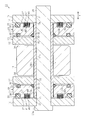
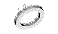
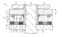
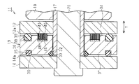
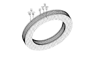
- Sectional drawing which shows a part of chain of FIG. FIG. 2 is a perspective view of a hair portion to which plate members in the chain of FIG. 1 are joined.
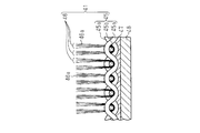
- the expanded sectional view which shows a part of FIG. The expanded sectional view of the principal part of the chain of the 1st modification.
- the expanded sectional view of the principal part of the chain of the 4th example of a change.
- FIG. 14 is a perspective view of a hair portion to which plate members in the chain of FIG. 13 are joined.
- the chain 11 includes a plurality of inner links 13 and a plurality of outer links 15.
- Each inner link 13 has a pair of inner link plates 12 that are opposed to each other in the width direction Y and are spaced apart from each other.
- Each outer link 15 has a pair of outer link plates 14 disposed so as to sandwich the pair of inner link plates 12 from the outside in the width direction Y.
- Each inner link plate 12 and each outer link plate 14 are each formed in a substantially rectangular plate shape extending along a longitudinal direction X orthogonal to the width direction Y. Both ends of the inner link plate 12 and both ends of the outer link plate 14 in the longitudinal direction X are rounded.
- the longitudinal direction X also coincides with the moving direction when the chain 11 moves when one end of the chain 11 is pulled.
- the inner link plate 12 and the outer link plate 14 facing each other in the width direction Y are arranged in parallel to each other.
- the chain 11 of the present embodiment is configured such that the distances between the inner link plates 12 at the first end and the second end of the inner link 13 in the longitudinal direction X are equal to each other, and the longitudinal direction The distance between the outer link plates 14 at the first end portion and the second end portion of the outer link 15 at X is equal to each other. That is, the chain 11 of this embodiment is a so-called flat type chain.
- circular first insertion holes 16 are formed so as to penetrate the inner link plate 12 in the width direction Y, respectively. That is, the width direction Y also coincides with the thickness direction of the inner link plate 12.
- two cylindrical bushings 17 are assembled so as to maintain a distance between the two inner link plates 12.
- Both ends of the bush 17 are fitted into the first insertion holes 16 of the pair of inner link plates 12, respectively. That is, the bush 17 is inserted through the first insertion holes 16 of the pair of inner link plates 12, and both end portions of the bush 17 protrude outward from the pair of inner link plates 12. Further, the bush 17 is inserted through a cylindrical roller 18 and supports the roller 18 rotatably. That is, the bush 17 is loosely fitted to the roller 18.
- the outer peripheral surfaces of the bushes 17 that protrude outward from the pair of inner link plates 12 constitute outer peripheral surfaces 17a.
- An annular seal portion 19 is fitted to the outer peripheral surface 17a. Therefore, the seal portion 19 is disposed between the outer side surface 12 a of each inner link plate 12 and the inner side surface 14 a of each outer link plate 14.
- the thickness of the seal portion 19 is set to be slightly thicker than the protruding length of the bush 17 from the outer surface 12a of the inner link plate 12. Therefore, a slight gap is formed between each end face 17b of the bush 17 and the inner side face 14a of the outer link plate 14 facing the end face 17b.
- circular second insertion holes 21 into which the cylindrical pins 20 are inserted are formed so as to penetrate the outer link plate 14 in the width direction Y, respectively. Yes. That is, the width direction Y coincides with the thickness direction of the outer link plate 14.
- the pin 20 has an outer diameter slightly smaller than the inner diameter of the bush 17.
- a diameter-enlarged portion 20 a for retaining that has a diameter slightly larger than the diameter of the second insertion hole 21 is formed.
- the pair of outer link plates 14 of the outer link 15 are rotatably connected to the pair of inner link plates 12 via pins 20 from the outside of the pair of inner link plates 12 of the inner link 13.
- a pair of bushes 17 are assembled between the pair of inner link plates 12 of the inner link 13.
- each pin 20 is fitted in the second insertion hole 21 of the pair of outer link plates 14 of the corresponding outer link 15 with both ends thereof inserted in the bush 17 corresponding to the intermediate portion thereof.
- both end portions of the pin 20 protrude outward through the second insertion holes 21 of the pair of outer link plates 14. Then, the pair of inner link plates 12 of the inner links 13 adjacent to each other in the longitudinal direction X and the pair of outer link plates 14 of the outer links 15 are rotated through pins 20 and bushes 17 at corresponding ends in the longitudinal direction X. It is connected freely.
- a lubricant (not shown) is filled between the outer peripheral surface 20b of the pin 20 and the inner peripheral surface 17c of the bush 17.
- the bush 17 and the pin 20 rotate relatively. At this time, the relative rotation between the bush 17 and the pin 20 is lubricated by the lubricant.
- the chain 11 of this embodiment is made of a steel material.
- the seal portion 19 includes an annular seal base 30 having rigidity.
- the seal base 30 is fitted to the outer peripheral surface 17 a of the bush 17.
- the seal base 30 in the present embodiment is made of a steel material.
- An inclined surface 32 is formed by chamfering an edge portion of the inner peripheral surface of the seal base 30 adjacent to the inner link plate 12.
- a first elastic ring 33 as an annular first elastic member is formed. Is arranged.
- the first elastic ring 33 is provided so as to surround the pin 20 in a state where the first elastic ring 33 is compressed and elastically deformed by the inclined surface 32, the outer surface 12a, and the outer peripheral surface 17a.
- a surface of the seal base 30 facing the outer surface 12 a of the inner link plate 12 constitutes a first facing surface 34. A slight gap is formed between the first facing surface 34 and the outer surface 12 a of the inner link plate 12.
- An annular first groove 35 is formed so as to surround the pin 20 at a position on the outer peripheral side of the radial direction center portion of the seal base 30 in the first facing surface 34 of the seal base 30.
- a second elastic ring 36 as an annular first elastic member is fitted in the first groove 35 so as to surround the pin 20.
- the second elastic ring 36 is arranged in a state of being compressed and elastically deformed.
- the second elastic ring 36 is in close contact with the outer surface 12a of the inner link plate 12 by its own elastic restoring force.
- the surface of the seal base 30 that faces the inner surface 14a of the outer link plate 14 constitutes a second facing surface 37.
- An annular second groove 38 is formed so as to surround the pin 20 at a position on the outer peripheral side of the radial center portion of the seal base 30 on the second facing surface 37.
- a third elastic ring 39 as an annular second elastic member is fitted into the second groove 38 so as to surround the pin 20.
- the third elastic ring 39 is arranged in a state of being compressed and elastically deformed.
- the third elastic ring 39 is in close contact with the inner side surface 14a of the outer link plate 14 with its own elastic restoring force, with a slightly weaker adhesion than the adhesion of the second elastic ring 36 to the inner link plate 12.
- the third elastic ring 39 is in sliding contact with the inner side surface 14 a of the outer link plate 14.
- the 1st elastic ring 33, the 2nd elastic ring 36, and the 3rd elastic ring 39 are each comprised by the O-ring formed with elastomers, such as rubber
- An annular third groove 40 is formed on the second opposing surface 37 of the seal base 30 so as to surround the pin 20 at a position closer to the inner peripheral side than the central portion in the radial direction of the seal base 30.
- An annular bristle 41 is fitted in the third groove 40 so as to surround the pin 20. Accordingly, the bristle portion 41 is disposed on the inner peripheral side of the seal base 30 with respect to the third elastic ring 39. In this case, the bristle portion 41 corresponds to the first bristle portion disposed between the seal base 30 and the inner side surface 14a of the outer link plate 14.
- the bristles 41 have a plurality of yarns that respectively extend along the width direction Y perpendicular to the radial direction of the pins 20. In the present embodiment, the plurality of yarns are constituted by a plurality of pile yarns 46 described later. A part of the bristle portion 41 is in sliding contact with the inner side surface 14 a of the outer link plate 14.
- the hair part 41 is comprised by the pile fabric.
- the pile fabric includes a base fabric 45 and a plurality of pile yarns 46 woven so as to stand up from the base fabric 45.
- the base fabric 45 and the pile yarn 46 are each formed of a synthetic resin.
- the base fabric 45 is configured by a woven fabric formed by alternately weaving the warp yarn 45a and the weft yarn 45b extending in a direction orthogonal to the direction in which the warp yarn 45a extends.
- Each pile yarn 46 is woven into the base fabric 45 so as to stand up from the base fabric 45 by being wound around the weft yarn 45b so as to form a U-shape.
- each pile yarn 46 is constituted by a multifilament yarn constituted by a plurality of filaments 46a.
- the density of the pile yarn 46 is set so that the number of filaments 46a constituting the pile yarn 46 is 70 to 100,000 per square centimeter.
- the plurality of pile yarns 46 are woven so as to stand up from the first side of the base fabric 45, and an annular metal plate material 48 is provided on the second side opposite to the first side of the base fabric 45. Are bonded via an adhesive layer 47.
- an adhesive or a double-sided pressure-sensitive adhesive tape can be used as the adhesive layer 47.
- each pile yarn 46 is in sliding contact with the inner side surface 14 a of the outer link plate 14 in a line contact state.
- the foreign matter that is about to enter the inside from the outside of the chain 11 first tries to enter the inside of the chain 11 through the space between the third elastic ring 39 and the inner side surface 14 a of the outer link plate 14. At this time, foreign matters such as water and dust are almost blocked by the third elastic ring 39, but foreign matters such as powder (for example, coal powder and iron ore powder) are not so much blocked by the third elastic ring 39.
- powder for example, coal powder and iron ore powder
- the foreign matter (particularly powder) that has entered between the third elastic ring 39 and the inner side surface 14a of the outer link plate 14 reaches the hair 41. Then, foreign matters (particularly powder) are effectively captured by the pile yarns 46 of the bristles 41. Thereafter, a small amount of foreign matter that has passed through the bristle portion 41 passes between the end surface 17b of the bush 17 and the inner side surface 14a of the outer link plate 14, and between the inner peripheral surface 17c of the bush 17 and the outer peripheral surface 20b of the pin 20. Enter.
- the entry of foreign matter such as water and dust is effectively suppressed by the third elastic ring 39, and the entry of foreign matter such as powder is effectively suppressed by the hair 41.
- the entry of foreign matter from the inside to the inside is effectively suppressed.
- the lubricant filled between the inner peripheral surface 17 c of the bush 17 and the outer peripheral surface 20 b of the pin 20 leaks to the outside of the chain 11, the lubricant is absorbed between the end surface 17 b of the bush 17 and the outer link plate 14. It goes to the hair part 41 through the space between the inner side surface 14a.
- a solid lubricant such as carbon is employed as the lubricant, the solid lubricant becomes powder and proceeds to the hair 41.
- the solid lubricant (powder) that has reached the hair 41 is effectively captured by the pile yarns 46 of the hair 41 as in the case of the foreign matter (particularly powder) described above. Thereafter, a slight amount of the solid lubricant that has passed through the bristles 41 passes between the third elastic ring 39 and the inner side surface 14 a of the outer link plate 14 and leaks to the outside of the chain 11.
- the position where the bristle portion 41 is provided in the seal portion 19 corresponds to the middle of the foreign material ingress path from the outside to the inside of the chain 11 and the middle of the lubricant leakage path from the inside of the chain 11 to the outside. is doing. For this reason, it is possible to effectively suppress leakage of lubricant (particularly powder) from the inside of the chain 11 to the outside while effectively suppressing entry of foreign matters (particularly powder) from the outside to the inside of the chain 11. be able to. Therefore, the lifetime of the chain 11 is extended.
- the seal portion 19 includes the bristles 41, foreign matter such as powder that is difficult to seal with the third elastic ring 39 can be effectively captured by the bristles 41. For this reason, the sealing performance with respect to the foreign material (especially powder) and lubricant (especially powder) by the seal part 19 can be improved. As a result, the life of the chain 11 is extended.
- the bristles 41 are disposed on the inner peripheral side of the seal base 30 with respect to the third elastic ring 39. For this reason, foreign matter such as powder that tries to penetrate through the third elastic ring 39 from the outside can be suitably captured by the hair portion 41.
- the bristle portion 41 is constituted by an annular pile fabric formed by weaving a plurality of pile yarns 46 upright from the base fabric 45.
- the base fabric 45 is formed by weaving warp yarn 45a and weft yarn 45b. For this reason, the density of the pile yarn 46 in the hair part 41 can be equalized easily. Moreover, since the hair part 41 is a pile fabric, handling of the hair part 41 becomes easy.
- the plurality of pile yarns 46 are woven so as to stand up from the first side of the base fabric 45, and the seal portion 19 is the second side of the base fabric 45 opposite to the first side. And an annular plate member 48 joined to each other. For this reason, the shape of the base fabric 45, and by extension, the shape of the pile fabric which comprises the hair part 41 can be stabilized by the board
- a third elastic ring 39 as a second elastic member is disposed between the seal base 30 and the inner side surface 14 a of the outer link plate 14, and the outer surface of the seal base 30 and the inner link plate 12.
- a second elastic ring 36 serving as a first elastic member is disposed between 12a and 12a.
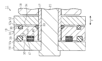
- Example of change The above embodiment may be modified as follows. -As shown in FIG. 5, you may replace and arrange the 3rd elastic ring 39 and the hair part 41 to which the board
- an annular groove 50 is formed on the inner peripheral side of the seal base 30 with respect to the bristles 41 on the second facing surface 37 of the seal base 30. And you may make it engage
- a part of the fourth elastic ring 51 is in close contact with the inner side surface 14 a of the outer link plate 14. In this way, the sealing performance by the seal portion 19 is further improved.
- annular groove 52 is formed on the outer peripheral side of the seal base 30 with respect to the third elastic ring 39 in the second facing surface 37 of the seal base 30. And you may make it engage
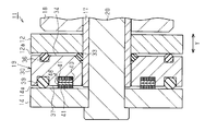
- the seal base 30 may be disposed in the width direction Y in the opposite direction to the above embodiment. That is, in the seal base 30, the third elastic ring 39 and the bristle portion 41 to which the plate material 48 is joined are arranged on the first facing surface 34 side facing the inner link plate 12, and the first elastic surface 39 facing the outer link plate 14. You may arrange
- the bristle portion 41 corresponds to a second bristle portion disposed between the seal base 30 and the outer side surface 12a of the inner link plate 12.
- an annular groove 53 is formed on the inner peripheral side of the seal base 30 with respect to the second elastic ring 36 on the first facing surface 34 of the seal base 30.
- channel 53 may be engage
- the seal base 30 includes an annular inner peripheral seal base 55 disposed so as to surround the pin 20, and a circle disposed so as to surround the outer peripheral surface of the inner peripheral seal base 55.
- FIG. Specifically, the seal base 30 is fitted to the outer peripheral surface of the inner peripheral side seal base 55 and the annular inner peripheral seal base 55 having rigidity to be fitted to the outer peripheral surface 17 a of the bush 17.
- the surface of the inner peripheral side seal base 55 that faces the outer surface 12 a of the inner link plate 12 constitutes a first facing surface 57.
- An annular first groove 58 is formed in a central portion of the inner surface side seal base 55 in the radial direction on the first facing surface 57.
- a first elastic ring 59 as an annular first elastic member is fitted in the first groove 58.
- a part of the first elastic ring 59 is in close contact with the outer surface 12 a of the inner link plate 12.
- a slight gap is formed between the first facing surface 57 of the inner peripheral side seal base 55 and the outer surface 12 a of the inner link plate 12.
- a first inclined surface 60 is formed by chamfering an edge portion of the outer peripheral surface of the inner peripheral side seal base 55 adjacent to the inner link plate 12.
- a second inclined surface 61 is formed by chamfering the edge portion of the inner peripheral surface of the inner peripheral side seal base 55 adjacent to the outer link plate 14.
- a region surrounded by the second inclined surface 61 of the inner peripheral side seal base 55, the inner side surface 14a of the outer link plate 14, and the outer peripheral surface 17a of the bush 17 has a second elasticity as an annular second elastic member.
- a ring 62 is arranged. The second elastic ring 62 is provided so as to surround the pin 20 in a state of being compressed and elastically deformed by the second inclined surface 61, the inner side surface 14a, and the outer peripheral surface 17a.
- the surface of the inner peripheral side seal base 55 that faces the inner surface 14 a of the outer link plate 14 constitutes a second facing surface 63.
- An annular second groove 64 is formed on the outer peripheral side of the inner peripheral side seal base 55 with respect to the second inclined surface 61 in the second facing surface 63.
- a bristle portion 41 to which a plate material 48 is joined is fitted in the second groove 64, and a tip end portion of the bristle portion 41 is in sliding contact with the inner side surface 14 a of the outer link plate 14.
- a slight gap is formed between the second facing surface 63 of the inner peripheral side seal base 55 and the inner side surface 14 a of the outer link plate 14.
- a third inclined surface 65 is formed by chamfering the edge portion of the inner peripheral surface of the outer peripheral side seal base 56 close to the inner link plate 12.
- An area surrounded by the third inclined surface 65 of the outer peripheral side seal base 56, the first inclined surface 60 of the inner peripheral side seal base 55, and the outer surface 12a of the inner link plate 12 is an annular first elastic member.
- the third elastic ring 66 is arranged.
- the third elastic ring 66 is provided so as to surround the pin 20 while being compressed and elastically deformed by the first inclined surface 60, the third inclined surface 65, and the outer surface 12a.
- the surface of the outer peripheral side seal base 56 that faces the outer surface 12 a of the inner link plate 12 constitutes a third facing surface 67.
- a slight gap is formed between the third facing surface 67 and the outer surface 12 a of the inner link plate 12.
- a surface of the outer peripheral side seal base 56 facing the inner side surface 14 a of the outer link plate 14 constitutes a fourth facing surface 68.
- the fourth facing surface 68 is in contact with the inner surface 14 a of the outer link plate 14.
- the plate material 48 of the two bristle parts 41 to which the plate material 48 is joined is fitted into the third groove 40 of the seal base 30 (shown in FIG. 12). May be included.
- the base groove 45 in the bristle portion 41 is joined to both surfaces of the plate material 48 (shown in FIG. 14) in the third groove 40 of the seal base 30 so as to be fitted. Also good.
- the bristle portion 41 (shown in FIG. 16) to which the plate material 48 is not joined may be fitted into the third groove 40 of the seal base 30. That is, only the hair 41 may be fitted into the third groove 40 of the seal base 30.
- the hair 41 may be attached to the inner side surface 14 a of the outer link plate 14 or the outer side surface 12 a of the inner link plate 12.
- the bristle part 41 may not be comprised with a pile fabric, but may be comprised with a some thread
- the plurality of yarns are appropriately joined to each other by an adhesive or the like so as to stand up from the inner side surface 14a of the outer link plate 14, the outer side surface 12a of the inner link plate 12, the seal base 30, and the like.
- the roller 18 may be omitted.
- the chain 11 can be rotated by a bush 17 and a pin 20 respectively, with a plurality of links each having two opposing link plates curved so that the width on one end side in the longitudinal direction X is narrower than the width on the other end side. It may be a so-called offset type chain connected to the.
Landscapes
- Engineering & Computer Science (AREA)
- General Engineering & Computer Science (AREA)
- Mechanical Engineering (AREA)
- Textile Engineering (AREA)
- Sealing Devices (AREA)
- Woven Fabrics (AREA)
Abstract
チェーン(11)は、互いに対向する一対の内リンクプレート(12)と、筒状のブシュ(17)と、ブシュ(17)に挿通されるピン(20)と、一対の外リンクプレート(14)と、シール部(19)とを含む。ブシュ(17)は、各内リンクプレート(12)の第1挿入孔(16)に挿通され、両端部が一対の内リンクプレート(12)の外側にそれぞれ突出している。一対の外リンクプレート(14)は、一対の内リンクプレート(12)を外側から挟むように配置される。ピン(20)の両端部は各外リンクプレート(14)の第2挿入孔(21)にそれぞれ挿通される。シール部(19)は、ピン(20)を囲むように各内リンクプレート(12)と各外リンクプレート(14)との間に配置される。シール部(19)は、シールベース(30)と、第2弾性リング(36)と、第3弾性リング(39)と、毛部(41)とを備える。第2弾性リング(36)は、シールベース(30)と内リンクプレート(12)との間においてピン(20)を囲むように配置される。第3弾性リング(39)及び毛部(41)は、シールベース(30)と外リンクプレート(14)との間においてピン(20)を囲むようにそれぞれ配置される。
Description
本発明は、内リンクプレートの外側面と外リンクプレートの内側面との間にシール部が配置されたチェーンに関する。
従来、この種のチェーンとしては、内リンクプレートと外リンクプレートとの間にオイルシールが配置されたものが知られている(例えば、特許文献1)。このようなオイルシールは、円環状のシールリングと、円環状の弾性リングとを備えている。弾性リングは、シールリングにおける内リンクプレートに近接する面及び外リンクプレートに近接する面にそれぞれ形成された円環状の溝にそれぞれ配置されている。そして、これら弾性リングが内リンクプレート及び外リンクプレートに摺接することにより、外部からの異物がピンとブシュとの間に進入することと、ピンとブシュとの間の潤滑油が外部へ漏れ出すこととを防止している。
上述のように構成されたチェーンにおいては、シールリングと内リンクプレートとの間、及びシールリングと外リンクプレートとの間を弾性リングのみによってシールしている。このため、特にチェーンを石炭粉や鉄鉱石粉などの微細な粉体が多く漂う環境下で使用する場合には、こうした粉体がチェーンの外部からピンとブシュとの間に進入し易くなる。そのため、ピンとブシュとの間のシール性を向上する上では改善の余地が残されている。
本発明は、このような従来技術に存在する問題点に着目してなされたものである。その目的とするところは、シール部によるシール性を向上することが可能なチェーンを提供することにある。
以下、上記の課題を解決するため、本願のチェーンは、互いに対向し、かつ離間して配置される一対の内リンクプレートと、各内リンクプレートに設けられた第1挿入孔に挿通され、両端部が前記一対の内リンクプレートの外側にそれぞれ突出する筒状のブシュと、前記ブシュに挿通されるピンと、前記一対の内リンクプレートを外側から挟むように配置される一対の外リンクプレートであって、前記ピンの両端部が各外リンクプレートに設けられた第2挿入孔にそれぞれ挿通される前記一対の外リンクプレートと、前記ピンを囲むように各内リンクプレートの外側面と各外リンクプレートの内側面との間に配置されるシール部とを備える。前記シール部は、剛性を有する環状のシールベースと、前記シールベースと前記内リンクプレートの外側面との間において前記ピンを囲むように配置される環状の第1弾性部材と、前記シールベースと前記外リンクプレートの内側面との間において前記ピンを囲むように配置される環状の第2弾性部材と、前記シールベースと前記内リンクプレートの外側面との間及び前記シールベースと前記外リンクプレートの内側面との間のうちの少なくとも一方において前記ピンを囲むように配置される少なくとも1つの環状の毛部であって、前記ピンの径方向と交差する方向にそれぞれ延びる複数の糸を有する前記少なくとも1つの毛部とを備える。
この構成によれば、シール部が複数の糸を有する環状の毛部を備えているため、Oリングなどの弾性部材でシールし難い粉体などの異物を捕捉することができる。したがって、シール部によるシール性を向上することが可能となる。
上記チェーンにおいて、前記少なくとも1つの毛部は、前記シールベースと前記外リンクプレートの内側面との間に配置される第1毛部を含み、前記第1毛部は、前記第2弾性部材よりも前記シールベースの内周側に配置されることが好ましい。
この構成によれば、外部から第2弾性部材を擦り抜けて進入しようとする粉体などの異物を第1毛部によって好適に捕捉することが可能となる。
上記チェーンにおいて、前記少なくとも1つの毛部は、前記シールベースと前記内リンクプレートの外側面との間に配置される第2毛部を含み、前記第2毛部は、前記第1弾性部材よりも前記シールベースの内周側に配置されることが好ましい。
上記チェーンにおいて、前記少なくとも1つの毛部は、前記シールベースと前記内リンクプレートの外側面との間に配置される第2毛部を含み、前記第2毛部は、前記第1弾性部材よりも前記シールベースの内周側に配置されることが好ましい。
この構成によれば、外部から第1弾性部材を擦り抜けて進入しようとする粉体などの異物を第2毛部によって好適に捕捉することが可能となる。
上記チェーンにおいて、前記少なくとも1つの毛部は、前記シールベースと前記外リンクプレートの内側面との間に配置される第1毛部と、前記シールベースと前記内リンクプレートの外側面との間に配置される第2毛部とを含み、前記第1毛部は前記第2弾性部材よりも前記シールベースの内周側に配置され、前記第2毛部は前記第1弾性部材よりも前記シールベースの内周側に配置されることが好ましい。
上記チェーンにおいて、前記少なくとも1つの毛部は、前記シールベースと前記外リンクプレートの内側面との間に配置される第1毛部と、前記シールベースと前記内リンクプレートの外側面との間に配置される第2毛部とを含み、前記第1毛部は前記第2弾性部材よりも前記シールベースの内周側に配置され、前記第2毛部は前記第1弾性部材よりも前記シールベースの内周側に配置されることが好ましい。
この構成によれば、外部から第1弾性部材又は第2弾性部材を擦り抜けて進入しようとする粉体などの異物を第1毛部又は第2毛部によって好適に捕捉することが可能となる。
上記チェーンにおいて、前記複数の糸は複数のパイル糸により構成され、タテ糸とヨコ糸とを織ることにより基布が形成され、前記少なくとも1つの毛部の各々は、前記基布から前記複数のパイル糸が起立するように織り込まれて形成された環状のパイル織物によって構成されていることが好ましい。
上記チェーンにおいて、前記複数の糸は複数のパイル糸により構成され、タテ糸とヨコ糸とを織ることにより基布が形成され、前記少なくとも1つの毛部の各々は、前記基布から前記複数のパイル糸が起立するように織り込まれて形成された環状のパイル織物によって構成されていることが好ましい。
この構成によれば、毛部におけるパイル糸の密度を容易に均一化することが可能となる。
上記チェーンにおいて、前記複数のパイル糸は前記基布の第1側から起立するように織り込まれ、前記シール部は前記基布における前記第1側とは反対側の第2側に接合された環状の板材を有していることが好ましい。
上記チェーンにおいて、前記複数のパイル糸は前記基布の第1側から起立するように織り込まれ、前記シール部は前記基布における前記第1側とは反対側の第2側に接合された環状の板材を有していることが好ましい。
この構成によれば、板材によって基布の形状を安定させることが可能となる。
上記チェーンにおいて、前記シールベースは、前記ピンを囲むように配置された環状の内周側シールベースと、前記内周側シールベースの外周面を囲むように配置された環状の外周側シールベースとを備えていることが好ましい。
上記チェーンにおいて、前記シールベースは、前記ピンを囲むように配置された環状の内周側シールベースと、前記内周側シールベースの外周面を囲むように配置された環状の外周側シールベースとを備えていることが好ましい。
この構成によれば、内周側シールベース及び外周側シールベースのうちのいずれか一方がシールベースとして機能しなくなった場合でも、他方がシールベースとして機能する。そのため、シールベースを長期間にわたってシールベースとして機能させることが可能となる。
本発明によれば、シール部によるシール性を向上することができる。
以下、チェーンの一実施形態を図面に従って説明する。
図1及び図2に示すように、チェーン11は、複数の内リンク13と、複数の外リンク15とを備えている。各内リンク13は、幅方向Yにおいて互いに対向し、かつ離間して配置される一対の内リンクプレート12を有している。各外リンク15は、一対の内リンクプレート12を幅方向Yの外側から挟むように配置される一対の外リンクプレート14を有している。
図1及び図2に示すように、チェーン11は、複数の内リンク13と、複数の外リンク15とを備えている。各内リンク13は、幅方向Yにおいて互いに対向し、かつ離間して配置される一対の内リンクプレート12を有している。各外リンク15は、一対の内リンクプレート12を幅方向Yの外側から挟むように配置される一対の外リンクプレート14を有している。
各内リンクプレート12及び各外リンクプレート14は、幅方向Yと直交する長手方向Xに沿って延びる略矩形板状にそれぞれ形成されている。長手方向Xにおける内リンクプレート12の両端部及び外リンクプレート14の両端部はそれぞれ丸みを帯びている。長手方向Xは、チェーン11の一端が引っ張られてそのチェーン11が移動する場合の移動方向とも一致している。
幅方向Yにおいて対向する内リンクプレート12及び外リンクプレート14は互いに平行に配置されている。換言すると、本実施形態のチェーン11は、長手方向Xにおける内リンク13の第1端部及び第2端部における内リンクプレート12同士の間隔が互いに等しくなるように構成されており、かつ長手方向Xにおける外リンク15の第1端部及び第2端部における外リンクプレート14同士の間隔が互いに等しくなるように構成されている。すなわち、本実施形態のチェーン11は所謂フラットタイプのチェーンである。
内リンクプレート12の長手方向Xにおける両端部には、円形の第1挿入孔16が内リンクプレート12を幅方向Yに貫通するようにそれぞれ形成されている。すなわち、幅方向Yは内リンクプレート12の厚さ方向とも一致している。内リンク13において対向する2つの内リンクプレート12の間には、これら2つの内リンクプレート12の間の距離を保つように円筒状の2つのブシュ17が組み付けられる。
ブシュ17の両端部は、一対の内リンクプレート12の第1挿入孔16に対してそれぞれ嵌合されている。すなわち、ブシュ17は一対の内リンクプレート12の第1挿入孔16に挿通され、ブシュ17の両端部は、一対の内リンクプレート12の外側にそれぞれ突出している。また、ブシュ17は、円筒状のローラ18に挿通されてローラ18を回転可能に支持している。すなわち、ブシュ17は、ローラ18に遊嵌されている。
ブシュ17における一対の内リンクプレート12の外側に突出した部分の外周面は外周面17aをそれぞれ構成している。外周面17aには、円環状のシール部19がそれぞれ嵌合されている。したがって、シール部19は、各内リンクプレート12の外側面12aと各外リンクプレート14の内側面14aとの間に配置されている。シール部19の厚さは、ブシュ17における内リンクプレート12の外側面12aからの突出長さよりも僅かに厚くなるように設定されている。したがって、ブシュ17の各端面17bとその端面17bに対向する外リンクプレート14の内側面14aとの間には、僅かな隙間が形成される。
外リンクプレート14の長手方向Xにおける両端部には、円柱状のピン20が挿嵌される円形の第2挿入孔21が、外リンクプレート14を幅方向Yに貫通するようにそれぞれ形成されている。すなわち、幅方向Yは外リンクプレート14の厚さ方向とも一致している。ピン20は、ブシュ17の内径よりも若干小さい外径を有している。ピン20の一端部には、第2挿入孔21の径よりも若干大きな径を有する抜け止め用の拡径部20aが形成されている。
外リンク15の一対の外リンクプレート14は、内リンク13の一対の内リンクプレート12の外側からピン20を介してその一対の内リンクプレート12に対して回動自在に連結される。内リンク13の一対の内リンクプレート12の間には、一対のブシュ17が組み付けられている。この場合、各ピン20は、その中間部が対応するブシュ17に挿通された状態で、その両端部が対応する外リンク15の一対の外リンクプレート14の第2挿入孔21に対してそれぞれ嵌合されている。
したがって、ピン20の両端部は一対の外リンクプレート14の第2挿入孔21を通って外側にそれぞれ突出している。そして、長手方向Xにおいて隣り合う内リンク13の一対の内リンクプレート12と外リンク15の一対の外リンクプレート14とが長手方向Xの対応する端部同士でピン20及びブシュ17を介して回動自在に連結される。
ピン20の外周面20bとブシュ17の内周面17cとの間には、図示しない潤滑剤が充填されている。チェーン11の使用時には、ブシュ17とピン20とが相対的に回動する。このとき、潤滑剤によってブシュ17とピン20との相対的な回動が潤滑される。本実施形態のチェーン11は、鋼材によって構成されている。
次に、シール部19の構成について詳述する。
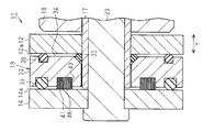
図2に示すように、シール部19は、剛性を有する円環状のシールベース30を備えている。シールベース30はブシュ17の外周面17aに嵌合されている。本実施形態におけるシールベース30は、鋼材によって構成されている。シールベース30の内周面における内リンクプレート12に近接する縁部には、面取りが施されることによって斜面32が形成されている。
図2に示すように、シール部19は、剛性を有する円環状のシールベース30を備えている。シールベース30はブシュ17の外周面17aに嵌合されている。本実施形態におけるシールベース30は、鋼材によって構成されている。シールベース30の内周面における内リンクプレート12に近接する縁部には、面取りが施されることによって斜面32が形成されている。
そして、シールベース30の斜面32と、内リンクプレート12の外側面12aと、ブシュ17の外周面17aとによって囲まれた領域には、円環状の第1弾性部材としての第1弾性リング33が配置されている。第1弾性リング33は、斜面32、外側面12a、及び外周面17aによって圧縮されて弾性変形された状態で、ピン20を囲むように設けられている。シールベース30における内リンクプレート12の外側面12aと対向する面は、第1対向面34を構成している。第1対向面34と内リンクプレート12の外側面12aとの間には、僅かな隙間が形成されている。
シールベース30の第1対向面34におけるシールベース30の径方向の中央部よりも外周側の位置には、円環状の第1溝35がピン20を囲むように形成されている。第1溝35には、円環状の第1弾性部材としての第2弾性リング36がピン20を囲むように嵌め込まれている。第2弾性リング36は、圧縮されて弾性変形された状態で配置されている。第2弾性リング36は、自らの弾性復元力によって内リンクプレート12の外側面12aに密着している。
シールベース30における外リンクプレート14の内側面14aと対向する面は第2対向面37を構成している。第2対向面37におけるシールベース30の径方向の中央部よりも外周側の位置には、円環状の第2溝38がピン20を囲むように形成されている。第2溝38には、円環状の第2弾性部材としての第3弾性リング39がピン20を囲むように嵌め込まれている。第3弾性リング39は、圧縮されて弾性変形された状態で配置されている。第3弾性リング39は、自らの弾性復元力によって、第2弾性リング36の内リンクプレート12に対する密着力よりも若干弱い密着力で、外リンクプレート14の内側面14aに密着している。換言すると、第3弾性リング39は、外リンクプレート14の内側面14aに摺接している。
シールベース30の第2対向面37と外リンクプレート14の内側面14aとの間には、僅かな隙間が形成されている。本実施形態において、第1弾性リング33、第2弾性リング36、及び第3弾性リング39は、ゴムなどのエラストマーによって形成されるOリングによってそれぞれ構成されている。
シールベース30の第2対向面37におけるシールベース30の径方向の中央部よりも内周側の位置には、円環状の第3溝40がピン20を囲むように形成されている。第3溝40には、円環状の毛部41がピン20を囲むように嵌め込まれている。したがって、毛部41は、第3弾性リング39よりもシールベース30の内周側に配置されている。この場合、毛部41は、シールベース30と外リンクプレート14の内側面14aとの間に配置される第1毛部に対応している。毛部41は、ピン20の径方向と直交する幅方向Yに沿ってそれぞれ延びる複数の糸を有している。本実施形態において、複数の糸は後述する複数のパイル糸46により構成されている。毛部41の一部は、外リンクプレート14の内側面14aに摺接している。
次に、毛部41の構成について詳述する。
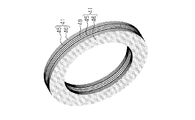
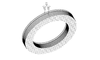
図3及び図4に示すように、毛部41は、パイル織物によって構成されている。パイル織物は、基布45と、その基布45から起立するように織り込まれた複数のパイル糸46とを備えている。基布45及びパイル糸46は、合成樹脂によりそれぞれ形成されている。基布45は、タテ糸45aと、タテ糸45aの延びる方向と直交する方向に延びるヨコ糸45bとを、交互に織りなすことによって形成される織布によって構成されている。各パイル糸46は、U字状をなすようにヨコ糸45bに巻かれて基布45から起立するように基布45に織り込まれている。
図3及び図4に示すように、毛部41は、パイル織物によって構成されている。パイル織物は、基布45と、その基布45から起立するように織り込まれた複数のパイル糸46とを備えている。基布45及びパイル糸46は、合成樹脂によりそれぞれ形成されている。基布45は、タテ糸45aと、タテ糸45aの延びる方向と直交する方向に延びるヨコ糸45bとを、交互に織りなすことによって形成される織布によって構成されている。各パイル糸46は、U字状をなすようにヨコ糸45bに巻かれて基布45から起立するように基布45に織り込まれている。
本実施形態において、各パイル糸46は、複数のフィラメント46aによって構成されたマルチフィラメント糸により構成されている。パイル糸46を構成するフィラメント46aの本数が1平方センチメートルあたり7~10万本となるように、パイル糸46の密度が設定されている。複数のパイル糸46は基布45の第1側から起立するように織り込まれており、基布45の第1側とは反対側の第2側には、円環状をなす金属製の板材48が接着層47を介して接合されている。接着層47としては、接着剤や両面粘着テープを用いることができる。
図2に示すように、毛部41は板材48側から第3溝40に嵌め込まれる。毛部41が第3溝40に嵌め込まれた状態では、各パイル糸46が外リンクプレート14の内側面14aに対して線接触した状態で摺接する。
次に、チェーン11の使用時におけるシール部19の作用について説明する。
チェーン11の使用時には、内リンクプレート12と外リンクプレート14とが相対的に回動する。このとき、第1弾性リング33及び第2弾性リング36の内リンクプレート12の外側面12aに対する密着力は、第3弾性リング39の外リンクプレート14の内側面14aに対する密着力よりも大きくなっている。このため、毛部41及び第3弾性リング39は外リンクプレート14の内側面14aに対して摺動する一方、第1弾性リング33及び第2弾性リング36は内リンクプレート12の外側面12aに対して摺動することなく、その外側面12aに対して密着した状態を維持する。
チェーン11の使用時には、内リンクプレート12と外リンクプレート14とが相対的に回動する。このとき、第1弾性リング33及び第2弾性リング36の内リンクプレート12の外側面12aに対する密着力は、第3弾性リング39の外リンクプレート14の内側面14aに対する密着力よりも大きくなっている。このため、毛部41及び第3弾性リング39は外リンクプレート14の内側面14aに対して摺動する一方、第1弾性リング33及び第2弾性リング36は内リンクプレート12の外側面12aに対して摺動することなく、その外側面12aに対して密着した状態を維持する。
したがって、チェーン11の外部に存在する水、塵埃、及び粉体などの異物がチェーン11の内部に進入する場合、異物は、第2弾性リング36と内リンクプレート12の外側面12aとの間を通ることができない。このため、異物は、シールベース30の第2対向面37と外リンクプレート14の内側面14aとの間を通ってチェーン11の内部へと進入する。
すなわち、チェーン11の外部から内部へ進入しようとする異物は、まず、第3弾性リング39と外リンクプレート14の内側面14aとの間を通ってチェーン11の内部へ進入しようとする。このとき、水や塵埃などの異物は、第3弾性リング39によってほとんどブロックされるが、粉体(例えば、石炭粉や鉄鉱石粉)などの異物は、第3弾性リング39によってさほどブロックされない。
そして、第3弾性リング39と外リンクプレート14の内側面14aとの間を通って進入した異物(特に粉体)は、毛部41に到達する。すると、異物(特に粉体)は、毛部41の各パイル糸46によって効果的に捕捉される。その後、毛部41を通り抜けた僅かな異物は、ブシュ17の端面17bと外リンクプレート14の内側面14aとの間を通ってブシュ17の内周面17cとピン20の外周面20bとの間に進入する。
このように、水や塵埃などの異物の進入が第3弾性リング39によって効果的に抑制され、粉体などの異物の進入が毛部41によって効果的に抑制される。このため、従来の構成に比べて異物がシール部19と外リンクプレート14との間を進行し難くなる、すなわち従来の構成に比べてシール部19によるシール性が向上するため、チェーン11の外部から内部への異物の進入が効果的に抑制される。
また、ブシュ17の内周面17cとピン20の外周面20bとの間に充填された潤滑剤がチェーン11の外部へ漏出する場合、潤滑剤は、ブシュ17の端面17bと外リンクプレート14の内側面14aとの間を通って毛部41へ向かう。このとき、潤滑剤としてカーボンなどの固体潤滑剤が採用されている場合には、当該固体潤滑剤が粉体となって毛部41へと進行する。
そして、毛部41に到達した固体潤滑剤(粉体)は、上述した異物(特に粉体)の場合と同様に、毛部41の各パイル糸46によって効果的に捕捉される。その後、毛部41を通り抜けた僅かな固体潤滑剤は、第3弾性リング39と外リンクプレート14の内側面14aとの間を通ってチェーン11の外部へ漏出する。
このように、シール部19における毛部41が設けられた位置は、チェーン11の外部から内部へ向かう異物の進入経路の途中及びチェーン11の内部から外部へ向かう潤滑剤の漏出経路の途中に対応している。このため、チェーン11の外部から内部へ向かう異物(特に粉体)の進入を効果的に抑制しつつ、チェーン11の内部から外部へ向かう潤滑剤(特に粉体)の漏出を効果的に抑制することができる。したがって、チェーン11の寿命が延びる。
以上詳述した実施形態によれば、次のような効果が発揮される。
(1)チェーン11において、シール部19は、毛部41を備えているため、第3弾性リング39によってシールし難い粉体などの異物を毛部41により効果的に捕捉することができる。このため、シール部19による異物(特に粉体)及び潤滑剤(特に粉体)に対するシール性を向上することができる。この結果、チェーン11の寿命が延びる。
(1)チェーン11において、シール部19は、毛部41を備えているため、第3弾性リング39によってシールし難い粉体などの異物を毛部41により効果的に捕捉することができる。このため、シール部19による異物(特に粉体)及び潤滑剤(特に粉体)に対するシール性を向上することができる。この結果、チェーン11の寿命が延びる。
(2)チェーン11において、毛部41は、第3弾性リング39よりもシールベース30の内周側に配置されている。このため、外部から第3弾性リング39を擦り抜けて進入しようとする粉体などの異物を毛部41によって好適に捕捉することができる。
(3)チェーン11において、毛部41は、基布45から複数のパイル糸46が起立するように織り込まれて形成された円環状のパイル織物によって構成されている。基布45は、タテ糸45aとヨコ糸45bとを織ることにより形成されている。このため、毛部41におけるパイル糸46の密度を容易に均一化することができる。また、毛部41がパイル織物であるため、毛部41の取り扱いが容易になる。
(4)チェーン11において、複数のパイル糸46は、基布45の第1側から立設するように織り込まれ、シール部19は、基布45における第1側とは反対側の第2側に接合された円環状の板材48を有している。このため、板材48によって基布45の形状、ひいては毛部41を構成するパイル織物の形状を安定させることができる。
(5)チェーン11において、シールベース30と外リンクプレート14の内側面14aとの間には第2弾性部材としての第3弾性リング39が配置され、シールベース30と内リンクプレート12の外側面12aとの間には第1弾性部材としての第2弾性リング36が配置されている。このため、第2弾性リング36及び第3弾性リング39によってシールベース30の位置を外リンクプレート14の内側面14aと内リンクプレート12の外側面12aとの間でバランスよく維持することができる。このため、毛部41(パイル織物)に過度な負荷がかかることを抑制することができる。
(変更例)
上記実施形態は次のように変更してもよい。
・図5に示すように、第3弾性リング39と、板材48が接合された毛部41とを入れ替えて配置してもよい。すなわち、毛部41よりもシールベース30の内周側に第3弾性リング39を配置してもよい。
上記実施形態は次のように変更してもよい。
・図5に示すように、第3弾性リング39と、板材48が接合された毛部41とを入れ替えて配置してもよい。すなわち、毛部41よりもシールベース30の内周側に第3弾性リング39を配置してもよい。
・図6に示すように、シールベース30の第2対向面37における毛部41よりもシールベース30の内周側に円環状の溝50を形成する。そして、この溝50に第2弾性部材としての第4弾性リング51を嵌め込むようにしてもよい。この場合、第4弾性リング51の一部は、外リンクプレート14の内側面14aに密着する。このようにすれば、シール部19によるシール性がさらに向上する。
・図7に示すように、シールベース30の第2対向面37における第3弾性リング39よりもシールベース30の外周側に円環状の溝52を形成する。そして、この溝52に板材48が接合された毛部41を嵌め込むようにしてもよい。このようにすれば、シール部19によるシール性がさらに向上する。
・図8に示すように、シールベース30を幅方向Yにおいて上記実施形態に対して逆向きに配置してもよい。すなわち、シールベース30において、内リンクプレート12と対向する第1対向面34側に第3弾性リング39と、板材48が接合された毛部41とを配置し、外リンクプレート14と対向する第2対向面37側に第1弾性リング33及び第2弾性リング36を配置してもよい。この場合、第1弾性リング33及び第2弾性リング36は第2弾性部材に対応し、第3弾性リング39は第1弾性部材に対応する。また、毛部41はシールベース30と内リンクプレート12の外側面12aとの間に配置された第2毛部に対応する。
・図9に示すように、シールベース30の第1対向面34における第2弾性リング36よりもシールベース30の内周側に円環状の溝53を形成する。そして、この溝53に板材48が接合された第2毛部としての毛部41を嵌め込み、さらにシールベース30における斜面32及び第1弾性リング33を省略してもよい。
・図10に示すように、シールベース30を、ピン20を囲むように配置された円環状の内周側シールベース55と、内周側シールベース55の外周面を囲むように配置された円環状の外周側シールベース56とによって構成してもよい。具体的には、シールベース30を、ブシュ17の外周面17aに嵌合される剛性を有する円環状の内周側シールベース55と、内周側シールベース55の外周面に嵌合される剛性を有する円環状の外周側シールベース56とによって構成してもよい。このようにすれば、内周側シールベース55及び外周側シールベース56のうちのいずれか一方がシールベースとして機能しなくなった場合でも、他方がシールベースとして機能するため、シールベース30を長期間にわたってシールベースとして機能させることができる。
次に、図10のチェーン11のシール部19の構成について詳述する。
図10に示すように、内周側シールベース55における内リンクプレート12の外側面12aと対向する面は第1対向面57を構成している。第1対向面57における内周側シールベース55の径方向の中央部には、円環状の第1溝58が形成されている。第1溝58には円環状の第1弾性部材としての第1弾性リング59が嵌め込まれている。第1弾性リング59の一部は内リンクプレート12の外側面12aに密着している。内周側シールベース55の第1対向面57と内リンクプレート12の外側面12aとの間には僅かな隙間が形成されている。内周側シールベース55の外周面における内リンクプレート12に近接する縁部には、面取りが施されることにより第1斜面60が形成されている。
図10に示すように、内周側シールベース55における内リンクプレート12の外側面12aと対向する面は第1対向面57を構成している。第1対向面57における内周側シールベース55の径方向の中央部には、円環状の第1溝58が形成されている。第1溝58には円環状の第1弾性部材としての第1弾性リング59が嵌め込まれている。第1弾性リング59の一部は内リンクプレート12の外側面12aに密着している。内周側シールベース55の第1対向面57と内リンクプレート12の外側面12aとの間には僅かな隙間が形成されている。内周側シールベース55の外周面における内リンクプレート12に近接する縁部には、面取りが施されることにより第1斜面60が形成されている。
内周側シールベース55の内周面における外リンクプレート14に近接する縁部には、面取りが施されることにより第2斜面61が形成されている。内周側シールベース55の第2斜面61と、外リンクプレート14の内側面14aと、ブシュ17の外周面17aとによって囲まれた領域には、円環状の第2弾性部材としての第2弾性リング62が配置されている。第2弾性リング62は、第2斜面61、内側面14a、及び外周面17aによって圧縮されて弾性変形された状態でピン20を囲むように設けられている。
内周側シールベース55における外リンクプレート14の内側面14aと対向する面は第2対向面63を構成している。第2対向面63における第2斜面61よりも内周側シールベース55の外周側には、円環状の第2溝64が形成されている。第2溝64には板材48が接合された毛部41が嵌め込まれており、毛部41の先端部は外リンクプレート14の内側面14aに摺接している。内周側シールベース55の第2対向面63と外リンクプレート14の内側面14aとの間には僅かな隙間が形成されている。
外周側シールベース56の内周面における内リンクプレート12に近接する縁部には、面取りが施されることにより第3斜面65が形成されている。外周側シールベース56の第3斜面65と、内周側シールベース55の第1斜面60と、内リンクプレート12の外側面12aとによって囲まれた領域には、円環状の第1弾性部材としての第3弾性リング66が配置されている。第3弾性リング66は、第1斜面60、第3斜面65、及び外側面12aによって圧縮されて弾性変形された状態でピン20を囲むように設けられている。
外周側シールベース56における内リンクプレート12の外側面12aと対向する面は、第3対向面67を構成している。第3対向面67と内リンクプレート12の外側面12aとの間には僅かな隙間が形成されている。そして、外周側シールベース56における外リンクプレート14の内側面14aと対向する面は、第4対向面68を構成している。第4対向面68は外リンクプレート14の内側面14aに当接されている。
・図11に示すように、シールベース30の第3溝40に、板材48が接合された2つの毛部41の板材48同士を接合して形成したもの(図12に示したもの)を嵌め込むようにしてもよい。
・図13に示すように、シールベース30の第3溝40に、毛部41における基布45を板材48の両面にそれぞれ接合して形成したもの(図14に示したもの)を嵌め込むようにしてもよい。
・図15に示すように、シールベース30の第3溝40に、板材48が接合されていない毛部41(図16に示したもの)を嵌め込むようにしてもよい。すなわち、シールベース30の第3溝40に、毛部41のみを嵌め込むようにしてもよい。
・チェーン11において、毛部41を、外リンクプレート14の内側面14a又は内リンクプレート12の外側面12aに取り付けてもよい。
・チェーン11において、毛部41をパイル織物により構成するのではなく、複数の糸によって構成してもよい。この場合、複数の糸は、外リンクプレート14の内側面14a、内リンクプレート12の外側面12a、及びシールベース30などから起立するように、適宜接着剤などによってそれらに接合される。
・チェーン11において、毛部41をパイル織物により構成するのではなく、複数の糸によって構成してもよい。この場合、複数の糸は、外リンクプレート14の内側面14a、内リンクプレート12の外側面12a、及びシールベース30などから起立するように、適宜接着剤などによってそれらに接合される。
・ローラ18は省略してもよい。
・チェーン11は、長手方向Xにおける一端側の幅が他端側の幅よりも狭くなるように湾曲した対向する2つのリンクプレートをそれぞれ備える複数のリンクをブシュ17及びピン20によってそれぞれ回動可能に連結した所謂オフセットタイプのチェーンであってもよい。
・チェーン11は、長手方向Xにおける一端側の幅が他端側の幅よりも狭くなるように湾曲した対向する2つのリンクプレートをそれぞれ備える複数のリンクをブシュ17及びピン20によってそれぞれ回動可能に連結した所謂オフセットタイプのチェーンであってもよい。
11…チェーン、12…内リンクプレート、14…外リンクプレート、16…第1挿入孔、17…ブシュ、19…シール部、20…ピン、21…第2挿入孔、30…シールベース、33…第1弾性部材としての第1弾性リング、36…第1弾性部材としての第2弾性リング、39…第2弾性部材としての第3弾性リング、41…毛部、45…基布、45a…タテ糸、45b…ヨコ糸、46…パイル糸、48…板材、51…第2弾性部材としての第4弾性リング、55…内周側シールベース、56…外周側シールベース、59…第1弾性部材としての第1弾性リング、62…第2弾性部材としての第2弾性リング、66…第1弾性部材としての第3弾性リング。
Claims (7)
- 互いに対向し、かつ離間して配置される一対の内リンクプレートと、
各内リンクプレートに設けられた第1挿入孔に挿通され、両端部が前記一対の内リンクプレートの外側にそれぞれ突出する筒状のブシュと、
前記ブシュに挿通されるピンと、
前記一対の内リンクプレートを外側から挟むように配置される一対の外リンクプレートであって、前記ピンの両端部が各外リンクプレートに設けられた第2挿入孔にそれぞれ挿通される前記一対の外リンクプレートと、
前記ピンを囲むように各内リンクプレートの外側面と各外リンクプレートの内側面との間に配置されるシール部とを備えたチェーンであって、
前記シール部は、
剛性を有する環状のシールベースと、
前記シールベースと前記内リンクプレートの外側面との間において前記ピンを囲むように配置される環状の第1弾性部材と、
前記シールベースと前記外リンクプレートの内側面との間において前記ピンを囲むように配置される環状の第2弾性部材と、
前記シールベースと前記内リンクプレートの外側面との間及び前記シールベースと前記外リンクプレートの内側面との間のうちの少なくとも一方において前記ピンを囲むように配置される少なくとも1つの環状の毛部であって、前記ピンの径方向と交差する方向にそれぞれ延びる複数の糸を有する前記少なくとも1つの毛部と
を備えたことを特徴とするチェーン。 - 前記少なくとも1つの毛部は、前記シールベースと前記外リンクプレートの内側面との間に配置される第1毛部を含み、前記第1毛部は、前記第2弾性部材よりも前記シールベースの内周側に配置されることを特徴とする請求項1に記載のチェーン。
- 前記少なくとも1つの毛部は、前記シールベースと前記内リンクプレートの外側面との間に配置される第2毛部を含み、前記第2毛部は、前記第1弾性部材よりも前記シールベースの内周側に配置されることを特徴とする請求項1に記載のチェーン。
- 前記少なくとも1つの毛部は、前記シールベースと前記外リンクプレートの内側面との間に配置される第1毛部と、前記シールベースと前記内リンクプレートの外側面との間に配置される第2毛部とを含み、
前記第1毛部は前記第2弾性部材よりも前記シールベースの内周側に配置され、
前記第2毛部は前記第1弾性部材よりも前記シールベースの内周側に配置されることを特徴とする請求項1に記載のチェーン。 - 前記複数の糸は複数のパイル糸により構成され、
タテ糸とヨコ糸とを織ることにより基布が形成され、
前記少なくとも1つの毛部の各々は、前記基布から前記複数のパイル糸が起立するように織り込まれて形成された環状のパイル織物によって構成されていることを特徴とする請求項1~請求項4のうちのいずれか一項に記載のチェーン。 - 前記複数のパイル糸は前記基布の第1側から起立するように織り込まれ、
前記シール部は前記基布における前記第1側とは反対側の第2側に接合された環状の板材を有していることを特徴とする請求項5に記載のチェーン。 - 前記シールベースは、前記ピンを囲むように配置された環状の内周側シールベースと、前記内周側シールベースの外周面を囲むように配置された環状の外周側シールベースとを備えていることを特徴とする請求項1~請求項6のうちのいずれか一項に記載のチェーン。
Priority Applications (2)
| Application Number | Priority Date | Filing Date | Title |
|---|---|---|---|
| KR1020177014981A KR101965087B1 (ko) | 2014-11-11 | 2015-11-10 | 체인 |
| CN201580058791.6A CN106922165B (zh) | 2014-11-11 | 2015-11-10 | 链条 |
Applications Claiming Priority (2)
| Application Number | Priority Date | Filing Date | Title |
|---|---|---|---|
| JP2014-228778 | 2014-11-11 | ||
| JP2014228778A JP6346071B2 (ja) | 2014-11-11 | 2014-11-11 | チェーン |
Publications (1)
| Publication Number | Publication Date |
|---|---|
| WO2016076291A1 true WO2016076291A1 (ja) | 2016-05-19 |
Family
ID=55954375
Family Applications (1)
| Application Number | Title | Priority Date | Filing Date |
|---|---|---|---|
| PCT/JP2015/081548 Ceased WO2016076291A1 (ja) | 2014-11-11 | 2015-11-10 | チェーン |
Country Status (4)
| Country | Link |
|---|---|
| JP (1) | JP6346071B2 (ja) |
| KR (1) | KR101965087B1 (ja) |
| CN (1) | CN106922165B (ja) |
| WO (1) | WO2016076291A1 (ja) |
Families Citing this family (1)
| Publication number | Priority date | Publication date | Assignee | Title |
|---|---|---|---|---|
| CN109835660B (zh) * | 2019-03-11 | 2024-07-09 | 杭州自强链传动有限公司 | 一种具有密封结构的链条 |
Citations (3)
| Publication number | Priority date | Publication date | Assignee | Title |
|---|---|---|---|---|
| JP2000291804A (ja) * | 1999-03-24 | 2000-10-20 | General Electric Co <Ge> | 封じ集成体とそれを持つ回転機械 |
| JP2009085253A (ja) * | 2007-09-27 | 2009-04-23 | Hitachi Metals Techno Ltd | チェン |
| JP2009264438A (ja) * | 2008-04-23 | 2009-11-12 | Tsubakimoto Chain Co | チェーン |
Family Cites Families (4)
| Publication number | Priority date | Publication date | Assignee | Title |
|---|---|---|---|---|
| JP3230734B2 (ja) * | 1997-09-10 | 2001-11-19 | 株式会社椿本チエイン | チェーンの連結ピン軸受部シール装置 |
| JP4255787B2 (ja) * | 2003-08-28 | 2009-04-15 | 株式会社椿本チエイン | シールチェーン |
| JP5094779B2 (ja) * | 2009-04-10 | 2012-12-12 | 株式会社椿本チエイン | シールチェーン |
| JP5255168B1 (ja) * | 2012-12-25 | 2013-08-07 | 三和テクノ株式会社 | パイル織編物からなる円筒状軸シール材 |
-
2014
- 2014-11-11 JP JP2014228778A patent/JP6346071B2/ja active Active
-
2015
- 2015-11-10 WO PCT/JP2015/081548 patent/WO2016076291A1/ja not_active Ceased
- 2015-11-10 CN CN201580058791.6A patent/CN106922165B/zh active Active
- 2015-11-10 KR KR1020177014981A patent/KR101965087B1/ko active Active
Patent Citations (3)
| Publication number | Priority date | Publication date | Assignee | Title |
|---|---|---|---|---|
| JP2000291804A (ja) * | 1999-03-24 | 2000-10-20 | General Electric Co <Ge> | 封じ集成体とそれを持つ回転機械 |
| JP2009085253A (ja) * | 2007-09-27 | 2009-04-23 | Hitachi Metals Techno Ltd | チェン |
| JP2009264438A (ja) * | 2008-04-23 | 2009-11-12 | Tsubakimoto Chain Co | チェーン |
Also Published As
| Publication number | Publication date |
|---|---|
| CN106922165A (zh) | 2017-07-04 |
| KR101965087B1 (ko) | 2019-04-02 |
| JP2016090021A (ja) | 2016-05-23 |
| JP6346071B2 (ja) | 2018-06-20 |
| CN106922165B (zh) | 2020-02-14 |
| KR20170080654A (ko) | 2017-07-10 |
Similar Documents
| Publication | Publication Date | Title |
|---|---|---|
| CN103354876B (zh) | 圆锥滚子轴承 | |
| US20110091143A1 (en) | Spherical bearing triple-lip seal | |
| JP5597410B2 (ja) | 分割型保持器のセグメント及び転がり軸受 | |
| KR20110115141A (ko) | 방사형 샤프트 실, 방사형 샤프트 실 어셈블리 및 설치 방법 | |
| JP5760402B2 (ja) | リニアガイド装置用サイドシール、リニアガイド装置 | |
| WO2016076291A1 (ja) | チェーン | |
| WO2013042312A1 (ja) | 直動案内装置 | |
| US20100098364A1 (en) | Roller with cage assembly | |
| JP2017061972A (ja) | 転がり軸受 | |
| WO2016031428A1 (ja) | チェーン | |
| KR20130055861A (ko) | 차량의 휠 베어링용 씰 | |
| JP2016090022A (ja) | チェーン | |
| JP2014177985A (ja) | 円すいころ軸受 | |
| CN104246250A (zh) | 直线导轨装置用供油装置以及直线导轨装置 | |
| JP5022000B2 (ja) | 密封装置および転がり軸受装置 | |
| WO2017109924A1 (ja) | 直動機構用サイドシールユニットおよび直動機構 | |
| JP6040199B2 (ja) | チェーン | |
| JP2011214702A (ja) | 保持器付きころ | |
| JP6662405B2 (ja) | シールチェーン | |
| JP2009052626A (ja) | 密封装置 | |
| JP6339159B2 (ja) | シールチェーン | |
| JP2015224719A (ja) | 玉軸受 | |
| JP2015183787A (ja) | 旋回軸受のシール構造 | |
| JP2013164118A (ja) | リニアガイド装置用サイドシール、リニアガイド装置 | |
| JP2015178841A (ja) | 直動案内装置のサイドシール |
Legal Events
| Date | Code | Title | Description |
|---|---|---|---|
| 121 | Ep: the epo has been informed by wipo that ep was designated in this application |
Ref document number: 15859760 Country of ref document: EP Kind code of ref document: A1 |
|
| NENP | Non-entry into the national phase |
Ref country code: DE |
|
| ENP | Entry into the national phase |
Ref document number: 20177014981 Country of ref document: KR Kind code of ref document: A |
|
| 122 | Ep: pct application non-entry in european phase |
Ref document number: 15859760 Country of ref document: EP Kind code of ref document: A1 |