WO2016068020A1 - ミキサ車 - Google Patents
ミキサ車 Download PDFInfo
- Publication number
- WO2016068020A1 WO2016068020A1 PCT/JP2015/079859 JP2015079859W WO2016068020A1 WO 2016068020 A1 WO2016068020 A1 WO 2016068020A1 JP 2015079859 W JP2015079859 W JP 2015079859W WO 2016068020 A1 WO2016068020 A1 WO 2016068020A1
- Authority
- WO
- WIPO (PCT)
- Prior art keywords
- fluid pressure
- mixer
- time
- mixer drum
- drive
- Prior art date
- Legal status (The legal status is an assumption and is not a legal conclusion. Google has not performed a legal analysis and makes no representation as to the accuracy of the status listed.)
- Ceased
Links
Images



Classifications
-
- B—PERFORMING OPERATIONS; TRANSPORTING
- B28—WORKING CEMENT, CLAY, OR STONE
- B28C—PREPARING CLAY; PRODUCING MIXTURES CONTAINING CLAY OR CEMENTITIOUS MATERIAL, e.g. PLASTER
- B28C5/00—Apparatus or methods for producing mixtures of cement with other substances, e.g. slurries, mortars, porous or fibrous compositions
- B28C5/42—Apparatus specially adapted for being mounted on vehicles with provision for mixing during transport
-
- B—PERFORMING OPERATIONS; TRANSPORTING
- B60—VEHICLES IN GENERAL
- B60P—VEHICLES ADAPTED FOR LOAD TRANSPORTATION OR TO TRANSPORT, TO CARRY, OR TO COMPRISE SPECIAL LOADS OR OBJECTS
- B60P3/00—Vehicles adapted to transport, to carry or to comprise special loads or objects
- B60P3/16—Vehicles adapted to transport, to carry or to comprise special loads or objects for carrying mixed concrete, e.g. having rotatable drums
Definitions
- the present invention relates to a mixer truck capable of mounting ready-mixed concrete.
- JP2000-33831A discloses a mixer vehicle including a mixer drum that is rotatably mounted on a vehicle body.
- the ready-mixed concrete is put into the mixer drum, and the ready-mixed concrete is stirred by the rotation of the mixer drum.
- the hydraulic oil gradually deteriorates due to the operation of the drive device. For this reason, when the degree of deterioration of the hydraulic oil exceeds the allowable value, the hydraulic oil needs to be replaced.
- the object of the present invention is to provide a mixer truck that can easily manage the replacement time of consumables.
- a mixer truck includes a mixer drum on which ready-mixed concrete can be mounted, a drive device that rotationally drives the mixer drum, a drive state detector that detects a drive state of the mixer drum, and a drive state of the mixer drum.
- a driving time integrating unit that integrates the driving time during which the mixer drum is rotating, and a consumable item related to the mixer vehicle when it is determined that the driving time accumulated by the driving time integrating unit exceeds a preset set time.
- a command generation unit that generates a command signal for notifying that the replacement time has arrived.
- FIG. 1A is a plan view of a mixer truck according to a first embodiment of the present invention.
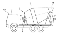
- FIG. 1B is a side view of the mixer truck.
- FIG. 2 is a control block diagram showing the configuration of the mixer truck.
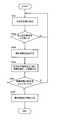
- FIG. 3 is a flowchart showing a routine for notifying the replacement time of consumables in the mixer truck.
- FIG. 4 is a flowchart showing a routine for informing the replacement time of consumables in the mixer truck according to the second embodiment of the present invention.
- FIG. 5 is a flowchart showing a routine for informing the replacement time of consumables in the mixer truck according to the third embodiment of the present invention.
- FIG. 6 is a flowchart showing a routine for notifying the replacement time of consumables in the mixer truck according to the fourth embodiment of the present invention.
- the mixer vehicle 100 is a vehicle including a cab 11 and a gantry 1.
- the mixer vehicle 100 includes a mixer drum 2 that is mounted on the gantry 1 and can be loaded with ready-mixed concrete, a drive device 4 that rotationally drives the mixer drum 2, and a controller 10 that controls the rotation of the mixer drum 2.
- the mixer truck 100 carries the ready-mixed concrete in the mixer drum 2 and carries it.
- illustration of the drive device 4 etc. is abbreviate
- the mixer drum 2 is a bottomed cylindrical container that is rotatably mounted on the gantry 1 and has an opening 2A at its rear end.
- the mixer drum 2 is mounted with an inclination so that the rotation axis O gradually increases from the front to the rear of the vehicle.
- a hopper 16 is provided at the upper rear portion of the opening 2A of the mixer drum 2.
- the ready-mixed concrete introduced from the opening 2A is guided to the opening 2A by the hopper 16.
- a flow guide 17 and a chute 18 are provided in the lower rear part of the opening 2 ⁇ / b> A of the mixer drum 2.
- the ready-mixed concrete discharged from the opening 2A is guided to the chute 18 by the flow guide 17 and discharged in a predetermined direction by the chute 18.
- the mixer drum 2 is rotationally driven using a traveling engine 3 mounted on the mixer vehicle 100 as a power source.
- the drive device 4 is driven by the rotation of the engine 3 and drives the mixer drum 2 to rotate by the fluid pressure of the working fluid.
- the rotational movement of the crankshaft in the engine 3 includes a power take-off mechanism 9 (PTO: Power take-off) for constantly taking power from the engine 3, and a drive shaft 8 (see FIG. 2).
- PTO Power take-off
- the power take-out mechanism 9 is provided with a rotation sensor 9a that detects the rotation speed of the engine 3 and outputs a rotation speed signal corresponding to the detected rotation speed to the controller 10. It is good also as a structure which detects the rotational speed of the drive shaft 8 using the rotation sensor 9a.
- the driving device 4 hydraulic oil is used as the working fluid.
- other incompressible fluid may be used as the working fluid instead of the working oil.
- the driving device 4 includes a hydraulic pump 5 as a fluid pressure pump that is driven by the engine 3 and discharges a working fluid, and a hydraulic motor 6 as a fluid pressure motor that is driven by the hydraulic pump 5 to rotationally drive the mixer drum 2. Prepare.
- the drive device 4 can forward / reverse and increase / decrease the mixer drum 2.
- the hydraulic pump 5 is rotationally driven by the power that is always taken out from the engine 3 through the power take-out mechanism 9. Therefore, the rotational speed of the hydraulic pump 5 is greatly affected by a change in the rotational speed of the engine 3 accompanying the traveling state of the vehicle. Therefore, in the mixer vehicle 100, the rotation speed of the hydraulic motor 6 is controlled by the controller 10 so that the mixer drum 2 is in the target rotation state according to the rotation speed of the engine 3.
- the hydraulic pump 5 is a swash plate type axial piston pump with variable capacity.
- the hydraulic pump 5 receives the control signal from the controller 10 and switches the tilt angle of the pump to the normal rotation direction or the reverse rotation direction.
- the hydraulic pump 5 includes a solenoid valve (not shown) for adjusting the tilt angle.
- the hydraulic pump 5 has its discharge direction and discharge capacity adjusted by switching the electromagnetic valve.
- the hydraulic oil discharged from the hydraulic pump 5 is supplied to the hydraulic motor 6 and the hydraulic motor 6 rotates.
- the rotation of the hydraulic motor 6 is transmitted to the mixer drum 2 via the speed reducer 7.
- the hydraulic pump 5 is provided with a pressure sensor 5a as a pressure detector for detecting the discharge pressure P of the discharged hydraulic oil.
- the pressure sensor 5 a outputs a load pressure signal corresponding to the detected hydraulic oil pressure P to the controller 10.
- the pressure sensor 5 a may be provided not in the hydraulic pump 5 but in the hydraulic motor 6 to detect the pressure of the hydraulic oil in the hydraulic motor 6. As described above, the pressure sensor 5 a detects the pressure of the hydraulic oil in the driving device 4.
- the hydraulic motor 6 is a swash plate type axial piston motor with variable capacity.
- the hydraulic motor 6 is rotationally driven in response to the supply of hydraulic oil discharged from the hydraulic pump 5.
- the hydraulic motor 6 includes an electromagnetic valve (not shown) that receives a second speed switching signal from the controller 10 and adjusts the tilt angle of a swash plate (not shown).
- the capacity of the hydraulic motor 6 can be switched in two stages, a small capacity for high speed rotation and a large capacity for normal rotation, by switching the electromagnetic valve.
- the hydraulic motor 6 is provided with a rotation sensor 6a as a rotation speed detector.
- the rotation sensor 6 a detects the rotation direction of the output shaft (not shown) and the rotation speed V of the output shaft, and outputs a rotation direction signal and a rotation speed signal to the controller 10.
- the controller 10 controls the driving device 4 and includes a CPU (Central Processing Unit), ROM (Read Only Memory), RAM (Random Access Memory), I / O interface (input / output interface), and the like. It consists of a microcomputer.
- the RAM stores data in the processing of the CPU
- the ROM stores in advance a control program of the CPU
- the I / O interface is used for input / output of information with a connected device.
- Control of the driving device 4 is realized by operating the CPU, RAM, and the like according to a program stored in the ROM.
- the controller 10 when the engine 3 is started by operating the ignition switch (not shown) in the cab 11 by the driver, the controller 10 is supplied with an ignition power source. As a result, the power relay 21 is switched, the main power from the main battery 23 is supplied to the controller 10, and the controller 10 is driven.
- a parking brake 31 In the cab 11, a parking brake 31, an operating device 32 for operating the mixer drum 2, and a notification device 35 for the driver are arranged.
- the parking brake 31 is provided with a detector that detects the lever position of the parking brake 31. When the parking brake 31 is applied, a stop signal is output from the detector to the controller 10.
- the operation device 32 includes a knob-type operation switch 32 a for switching the rotation direction and rotation speed of the mixer drum 2, a stop switch 32 b for emergency stop of the rotation of the mixer drum 2, and the mixer drum 2 is automatically rotated by stirring. And an automatic stirring switch 32c for the purpose.
- a command signal is output from the operating device 32 to the controller 10 based on the driver operating the operation switches 32a to 32d. Based on the command signal, the controller 10 determines the target rotation state of the mixer drum 2, specifically, the rotation direction and the rotation speed.
- the controller 10 determines that the vehicle is traveling. As a result, the controller 10 automatically rotates the mixer drum 2 while stirring to prevent the ready-mixed concrete from being discharged and to maintain the quality of the ready-mixed concrete.
- the controller 10 can reversely rotate the mixer drum 2 by operating the operation device 32 even when the vehicle is traveling.
- the controller 10 operates the operating device 32 to reversely rotate the mixer drum 2 so that the ready-mixed concrete in the mixer drum 2 can be discharged to the outside. Make it possible.
- a rear operation device 38 for enabling the operation of the mixer drum 2 outside the mixer vehicle 100 is disposed at the rear of the mixer vehicle 100.
- the rear operation device 38 includes a knob-type operation switch 38 a for switching the rotation direction and rotation speed of the mixer drum 2 and a stop switch 38 b for emergency stop of the rotation of the mixer drum 2.
- a command signal is output from the rear operation device 38 to the controller 10.
- the controller 10 controls the operation of the hydraulic pump 5 and the hydraulic motor 6 so that the rotation direction and the rotation speed of the mixer drum 2 are in a target rotation state according to the calculated rotation speed of the engine 3. Specifically, the controller 10 calculates the discharge direction and discharge capacity of the hydraulic pump 5 and calculates the capacity of the hydraulic motor 6 so that the rotation direction and rotation speed of the mixer drum 2 are in the target rotation state.
- the control signal is output to the hydraulic pump 5 and the second speed switching signal is output to the hydraulic motor 6.
- the controller 10 receives a load pressure signal from the hydraulic pump 5 through the pressure sensor 5a and a rotation direction signal and a rotation speed signal from the hydraulic motor 6 through the rotation sensor 6a.
- the controller 10 controls the operations of the hydraulic pump 5 and the hydraulic motor 6 based on these input signals.
- the mixer vehicle 100 is provided with a notification device 35 that notifies the driver that it is time to replace the hydraulic oil filled in the drive device 4.
- the notification device 35 is a character display device or lamp that notifies the driver so that the driver can visually recognize the device, or a buzzer or speaker that notifies the driver by sound or voice.
- the controller 10 includes a drive time integration unit 14 that integrates the drive time during which the mixer drum 2 is rotating according to the drive state of the mixer drum 2 detected by the drive state detector, and a notification device according to the integrated drive time T.
- An exchange time notification command generating unit (also simply referred to as a “command generating unit”) 15 that generates a command signal for controlling the operation of 35.
- the mixer vehicle 100 uses the rotation sensor 6a as a drive state detector.
- the drive time integrating unit 14 determines whether or not the mixer drum 2 is rotating based on the detection signal of the rotation sensor 6a.
- the command generation unit 15 generates a command signal for operating the notification device 35 and determines the command signal to the notification device 35 when it is determined that the accumulated drive time T has exceeded a preset set time LT. Send.
- the notification device 35 operates in response to this command signal, and notifies the driver that the time for replacing the hydraulic oil has come.
- the notification device 35 may be provided in a place away from the mixer truck 100 (for example, a management center where a manager of the mixer truck is present).
- the command generation unit 15 sends a command signal to the notification device 35 using a wireless device (not shown).
- the notification device 35 operates in response to a command signal through the wireless device, and notifies the administrator that it is time to replace the hydraulic oil as a consumable.
- the controller 10 repeatedly executes this routine at regular intervals, for example, every 10 milliseconds while the engine 3 is operating.
- step S101 the controller 10 reads the rotation speed V of the hydraulic motor 6 from the detection signal of the rotation sensor 6a.
- the rotational speed V of the hydraulic motor 6 is used as a parameter for determining the driving state of the mixer drum 2.
- the rotational speed V of the hydraulic motor 6 is 0 (zero)
- it is determined that the driving state of the mixer drum 2 is the time when the operation of the hydraulic motor 6 stops and the operation of the mixer drum 2 stops.
- the rotational speed V of the hydraulic motor 6 is not 0, the driving state of the mixer drum 2 is determined to be an operation in which the hydraulic motor 6 is operated and the mixer drum 2 is rotationally driven.
- step S102 the controller 10 determines whether or not the read rotation speed V is zero.
- step S102 If it is determined in step S102 that the driving state of the mixer drum 2 is during operation of the mixer drum 2 whose rotation speed V is not 0, the processing of the controller 10 proceeds to step S103. On the other hand, when it is determined in step S102 that the rotation speed V is 0, the processing of the controller 10 returns to the start.
- step S103 the controller 10 integrates the time during which the hydraulic motor 6 and the mixer drum 2 are rotating.
- step S104 the controller 10 determines whether or not the accumulated driving time T is equal to or longer than a preset setting time LT.
- step S104 If it is determined in step S104 that the drive time T has reached the set time LT, the processing of the controller 10 proceeds to step S105. On the other hand, if it is determined in step S104 that the drive time T has not reached the set time LT, the processing of the controller 10 returns to the start.
- step S105 the controller 10 generates a command signal for operating the notification device 35 and sends the command signal to the notification device 35, and ends this routine.
- the notification device 35 operates in response to a command signal from the controller 10 and notifies the driver that the hydraulic oil replacement time has been reached.
- the mixer vehicle 100 corresponds to the drive device 4 that rotationally drives the mixer drum 2, the rotation sensor 6 a (drive state detector) that detects the drive state of the mixer drum 2, and the drive state of the mixer drum 2.
- the driving time integrating unit 14 for integrating the driving time during which the mixer drum 2 is rotating, and the driving time T integrated by the driving time integrating unit 14 is determined to have exceeded a preset set time LT.
- a command generation unit 15 that generates a command signal for notifying that it is time to replace the consumables.
- steps S101 to S103 correspond to the processing performed by the drive time integrating unit 14.
- steps S ⁇ b> 104 and S ⁇ b> 105 correspond to processing performed by the command generation unit 15.
- the driver is notified that the hydraulic oil replacement time has been reached as the drive time T for rotating the mixer drum 2 reaches the set time LT.
- the operator operates a reset switch (not shown), so that the driving time T accumulated in the driving time integrating unit 14 is set to 0 (zero). Calculation of the drive time T is newly started.
- the mixer vehicle 100 uses a rotation sensor 6a (rotation speed detector) that detects the rotation speed V of the hydraulic motor 6 that drives the mixer drum 2 as a drive state detector. Since the drive time integration unit 14 integrates the drive time during which the hydraulic motor 6 is rotating based on the detection result of the rotation sensor 6a, the drive time integration unit 14 can accurately determine when the mixer drum 2 is driven.
- a rotation sensor 6a rotation speed detector
- the drive time integrating unit determines that the mixer drum 2 is rotating based on the detection signal of the rotation sensor 6a, the hydraulic pressure for driving the hydraulic motor 6 decreases based on the detection signal of the pressure sensor 5a. Accordingly, the time during which the hydraulic motor 6 is rotating is corrected so as to be shortened, and the corrected time is integrated.
- the controller 10 repeatedly executes this routine at regular intervals, for example, every 10 milliseconds while the engine 3 is operating.
- step S201 the controller 10 reads the rotation speed V of the hydraulic motor 6 from the detection signal of the rotation sensor 6a.
- step S202 the controller 10 determines whether or not the read rotation speed V is 0 (zero).
- step S202 when it is determined that the driving state of the mixer drum 2 is during operation of the mixer drum 2 whose rotation speed V is not 0, the processing of the controller 10 proceeds to step S203. On the other hand, if it is determined in step S202 that the rotation speed V is 0, the processing of the controller 10 returns to the start.
- step S203 the controller 10 reads the discharge pressure P in the hydraulic pump 5 from the detection signal of the pressure sensor 5a.
- step S204 the controller 10 calculates a correction coefficient K based on a map (not shown) set in advance according to the read discharge pressure P.
- the correction coefficient K is set to 0.5 in a low load state where the discharge pressure P is less than or equal to a predetermined value P2 (empty state where no green concrete is contained in the mixer drum 2), and the discharge pressure P is a predetermined value.
- the correction coefficient K is set to 1.0 in a high load state higher than P2 (a state in which ready-mixed concrete is contained in the mixer drum 2).
- step S205 the controller 10 multiplies the time during which the hydraulic motor 6 rotates by the correction coefficient K and accumulates the drive time T after multiplication.
- step S204 is not limited to the configuration described above, and may be set so that the correction coefficient K is gradually increased as the discharge pressure P increases. As a result, it is possible to correct the time for which the hydraulic motor 6 rotates in response to an increase or decrease in the load with which the drive device 4 drives the mixer drum 2 depending on the amount of ready-mixed concrete on the mixer drum 2.
- step S206 the controller 10 determines whether or not the corrected and integrated drive time T has reached a preset set time LT.
- step S206 If it is determined in step S206 that the drive time T has reached the set time LT, the processing of the controller 10 proceeds to step S207. On the other hand, if it is determined in step S206 that the drive time T has not reached the set time LT, the processing of the controller 10 returns to the start.
- step S207 the controller 10 generates a command signal for operating the notification device 35 and sends the command signal to the notification device 35, and ends this routine.
- the notification device 35 operates in response to a command signal from the controller 10 and notifies the driver that the hydraulic oil replacement time has been reached.
- the mixer vehicle 100 includes the pressure sensor 5 a (fluid pressure detector) that detects the hydraulic pressure P that drives the hydraulic motor 6, and the drive time integration unit drives the hydraulic motor 6. As the oil pressure P decreases, the time for which the hydraulic motor 6 rotates is corrected to be short, and the corrected time is integrated.
- the pressure sensor 5 a fluid pressure detector
- steps S201 to S205 correspond to the processing performed by the drive time integrating unit.
- the drive device 4 is loaded to drive the mixer drum 2 by correcting the hydraulic motor 6 to rotate so that the time for which the hydraulic motor 6 rotates is shortened as the hydraulic pressure P for driving the hydraulic motor 6 decreases. Accordingly, it is possible to accurately determine the hydraulic oil replacement time.
- the rotation sensor 6a is used as the driving state detector.
- the same control is performed using the pressure sensor 5a as the driving state detector. Is executed.
- the drive time integrating unit compares the discharge pressure P in the hydraulic pump 5 detected by the pressure sensor 5a with a predetermined set value P1. Then, it is determined whether or not the mixer drum 2 is rotating.
- the set value P1 is a value set in advance based on the minimum value of the pressure P of the hydraulic fluid guided from the hydraulic pump 5 to the hydraulic motor 6 when the hydraulic motor 6 rotates the mixer drum 2.
- the drive time integrating unit determines that the operation is during the rotation of the mixer drum 2.
- the controller 10 repeatedly executes this routine at regular intervals, for example, every 10 milliseconds while the engine 3 is operating.
- step S301 the controller 10 reads the discharge pressure P that drives the hydraulic motor 6 from the detection signal of the pressure sensor 5a.
- the discharge pressure P for driving the hydraulic motor 6 is used as a parameter for determining the driving state of the mixer drum 2.
- the discharge pressure P for driving the hydraulic motor 6 is equal to or lower than the set pressure P1
- it is determined that the driving state of the mixer drum 2 is when the operation is stopped when the rotation of the mixer drum 2 by the hydraulic motor 6 stops.
- the discharge pressure P for driving the hydraulic motor 6 is higher than the set pressure P1
- the driving state of the mixer drum 2 is determined to be during operation in which the mixer drum 2 is rotationally driven by the hydraulic motor 6.
- step S302 the controller 10 determines whether or not the read discharge pressure P is higher than the set pressure P1.
- step S302 If it is determined in step S302 that the discharge pressure P is higher than the set pressure P1, the process of the controller 10 proceeds to step S303. On the other hand, when it is determined in step S302 that the discharge pressure P is equal to or lower than the set value P1, the process of the controller 10 returns to the start.
- step S303 the controller 10 integrates the time during which the discharge pressure P is higher than the set pressure P1 and the mixer drum 2 is rotating.
- step S304 the controller 10 determines whether or not the accumulated drive time T has reached a preset time LT.
- step S304 If it is determined in step S304 that the drive time T has reached the set time LT, the process of the controller 10 proceeds to step S305. On the other hand, if it is determined in step S304 that the drive time T has not reached the set time LT, the processing of the controller 10 returns to the start.
- step S305 the controller 10 generates a command signal for operating the notification device 35 and sends the command signal to the notification device 35, and ends this routine.
- the notification device 35 operates in response to a command signal from the controller 10 and notifies the driver that the hydraulic oil replacement time has been reached.
- the mixer vehicle 100 uses the pressure sensor 5a (fluid pressure detector) that detects the discharge pressure P that drives the hydraulic motor 6 that drives the mixer drum 2 as the drive state detector. Since the drive time integration unit integrates the time during which the discharge pressure P for driving the hydraulic motor 6 exceeds the preset value P1, the operation time when the mixer drum 2 is driven can be accurately determined.
- the pressure sensor 5a fluid pressure detector
- steps S301 to S303 correspond to the processing performed by the drive time integrating unit.
- the drive time integration unit reduces the hydraulic pressure that drives the hydraulic motor 6 based on the detection signal of the pressure sensor 5a. Accordingly, the time required for the hydraulic motor 6 to rotate is shortened and the corrected time is integrated.
- the controller 10 repeatedly executes this routine at regular intervals, for example, every 10 milliseconds while the engine 3 is operating.
- step S401 the controller 10 reads the discharge pressure P of the hydraulic motor 6 from the detection signal of the pressure sensor 5a.
- step S402 the controller 10 determines whether or not the read discharge pressure P is higher than the set pressure P1.
- step S402 If it is determined in step S402 that the discharge pressure P is higher than the set pressure P1, the process of the controller 10 proceeds to step S403. On the other hand, when it is determined in step S402 that the discharge pressure P is equal to or less than the set value P1, the process of the controller 10 returns to the start.
- step S403 the controller 10 calculates a correction coefficient K based on a map (not shown) set in advance according to the read discharge pressure P.
- the correction coefficient K is set to 0.5 in a low load state where the discharge pressure P is less than or equal to a predetermined value P2 (empty state where no green concrete is contained in the mixer drum 2), and the discharge pressure P is a predetermined value.
- the correction coefficient K is set to 1.0 in a high load state higher than P2 (a state in which ready-mixed concrete is contained in the mixer drum 2).
- step S404 the controller 10 adds the correction coefficient K to the time when the discharge pressure P exceeds the set value P1, and accumulates the drive time T after multiplication.
- step S405 the controller 10 determines whether or not the corrected and integrated drive time T has reached a preset set time LT.
- step S405 If it is determined in step S405 that the drive time T has reached the set time LT, the processing of the controller 10 proceeds to step S406. On the other hand, if it is determined in step S405 that the drive time T has not reached the set time LT, the processing of the controller 10 returns to the start.
- step S406 the controller 10 generates a command signal for operating the notification device 35 and sends the command signal to the notification device 35, and ends this routine.
- the notification device 35 operates in response to a command signal from the controller 10 and notifies the driver that the hydraulic oil replacement time has been reached.
- the mixer vehicle 100 includes the pressure sensor 5 a (fluid pressure detector) that detects the hydraulic pressure P that drives the hydraulic motor 6, and the drive time integrating unit drives the hydraulic motor 6. As the oil pressure P decreases, the correction time is corrected so as to shorten the time when the discharge pressure P that drives the hydraulic motor 6 exceeds the set value P1, and the corrected time is integrated.
- the pressure sensor 5 a fluid pressure detector
- steps S401 to S404 correspond to the processing performed by the drive time integration unit.
- the drive device 4 causes the mixer drum 2 to be adjusted by correcting the discharge pressure P to drive the hydraulic motor 6 so that the time during which the discharge pressure P exceeds the set value P ⁇ b> 1 is shortened.
- the hydraulic oil replacement time can be accurately determined according to the driving load.
- the command generation unit 15 of the above-described embodiment generates a command signal for notifying the replacement timing of the hydraulic oil circulating through the drive device 4 as a consumable item related to the mixer vehicle according to the drive time of the mixer drum 2.
- the command generation unit may determine the replacement timing of the following parts as consumables related to the mixer vehicle according to the discharge pressure of the hydraulic pump that drives the hydraulic motor, the rotational speed of the hydraulic motor, and the like.
- the command generation unit may determine the replacement timing of the following parts as consumables related to the mixer truck by measuring the amount of loaded concrete or the amount of discharged concrete.
- a liner (not shown) attached to the inner wall of the hopper 16 A liner (not shown) attached to the inner wall of the flow guide 17 A liner (not shown) attached to the inner wall of the chute 18
Landscapes
- Engineering & Computer Science (AREA)
- Mechanical Engineering (AREA)
- Structural Engineering (AREA)
- Health & Medical Sciences (AREA)
- Public Health (AREA)
- Transportation (AREA)
- Preparation Of Clay, And Manufacture Of Mixtures Containing Clay Or Cement (AREA)
Abstract
Description
図1A、図1Bを参照して、ミキサ車100の全体構成について説明する。
次に、本発明の第2実施形態を説明する。以下では、上記第1実施形態と異なる点を中心に説明し、上記第1実施形態のミキサ車と同一の構成には同一の符号を付して説明を省略する。
次に、本発明の第3実施形態を説明する。以下では、上記第1実施形態と異なる点を中心に説明し、上記第1実施形態のミキサ車と同一の構成には同一の符号を付して説明を省略する。
次に、本発明の第4実施形態を説明する。以下では、上記第3実施形態と異なる点を中心に説明し、上記第3実施形態のミキサ車と同一の構成には同一の符号を付して説明を省略する。
・減速機(ギアボックス)7を構成する部品(図示省略)、または減速機7に充填される潤滑油
・油圧ポンプ5
・油圧モータ6
・ミキサドラム2の外周レール部に転接するドラムローラ(図示省略)
・ドライブシャフト8またはドライブシャフト8に回転を伝達するカップリング(図示省略)
・ミキサドラム2の内壁から突出するブレード(図示省略)
・ミキサドラム2の摺動部に介装されるシール(図示省略)
また、指令生成部は、ミキサ車に関する消耗品として下記の部品の交換時期を、生コンクリートの搭載量または排出量を計測して判定としてもよい。
・ホッパ16の内壁に取り付けられるライナ(図示省略)
・フローガイド17の内壁に取り付けられるライナ(図示省略)
・シュート18の内壁に取り付けられるライナ(図示省略)
Claims (5)
- ミキサ車であって、
生コンクリートを搭載可能なミキサドラムと、
前記ミキサドラムを回転駆動する駆動装置と、
前記ミキサドラムの駆動状態を検知する駆動状態検知器と、
前記ミキサドラムの駆動状態に応じて前記ミキサドラムが回転している駆動時間を積算する駆動時間積算部と、
前記駆動時間積算部にて積算された前記駆動時間が予め設定された設定時間を超えたと判定された場合に、前記ミキサ車に関する消耗品の交換時期が来たことを報知するための指令信号を生成する指令生成部と、を備えるミキサ車。 - 請求項1に記載のミキサ車であって、
前記駆動装置は、
作動流体を吐出する流体圧ポンプと、
前記流体圧ポンプが吐出した作動流体によって駆動され、前記ミキサドラムを回転駆動する流体圧モータと、を備え、
前記駆動状態検知器は、前記流体圧モータの回転速度を検知する回転速度検知器であり、
前記駆動時間積算部は、前記回転速度検知器の検知結果に基づいて前記流体圧モータが回転している時間を積算するミキサ車。 - 請求項2に記載のミキサ車であって、
前記流体圧モータを駆動する流体圧を検知する流体圧検知器をさらに備え、
前記駆動時間積算部は、前記流体圧モータを駆動する流体圧が低下するのに応じて前記流体圧モータが回転している時間を短くするように補正し補正後の時間を積算するミキサ車。 - 請求項1に記載のミキサ車であって、
前記駆動装置は、
作動流体を吐出する流体圧ポンプと、
前記流体圧ポンプが吐出した作動流体によって駆動され、前記ミキサドラムを回転駆動する流体圧モータと、を備え、
前記駆動状態検知器は、前記流体圧モータを駆動する流体圧を検知する流体圧検知器であり、
前記駆動時間積算部は、前記流体圧検知器の検知結果に基づいて前記流体圧モータを駆動する流体圧が予め設定された設定圧を超える時間を積算するミキサ車。 - 請求項4に記載のミキサ車であって、
前記駆動時間積算部は、前記流体圧モータを駆動する流体圧が低下するのに応じて前記流体圧モータを駆動する流体圧が前記設定圧を超える時間を短くするように補正し補正後の時間を積算するミキサ車。
Priority Applications (2)
| Application Number | Priority Date | Filing Date | Title |
|---|---|---|---|
| AU2015338054A AU2015338054B2 (en) | 2014-10-29 | 2015-10-22 | Mixer vehicle |
| NZ731608A NZ731608A (en) | 2014-10-29 | 2015-10-22 | Mixer vehicle configured to notify replacement timing of consumables |
Applications Claiming Priority (2)
| Application Number | Priority Date | Filing Date | Title |
|---|---|---|---|
| JP2014-219945 | 2014-10-29 | ||
| JP2014219945A JP6438274B2 (ja) | 2014-10-29 | 2014-10-29 | ミキサ車 |
Publications (1)
| Publication Number | Publication Date |
|---|---|
| WO2016068020A1 true WO2016068020A1 (ja) | 2016-05-06 |
Family
ID=55857359
Family Applications (1)
| Application Number | Title | Priority Date | Filing Date |
|---|---|---|---|
| PCT/JP2015/079859 Ceased WO2016068020A1 (ja) | 2014-10-29 | 2015-10-22 | ミキサ車 |
Country Status (4)
| Country | Link |
|---|---|
| JP (1) | JP6438274B2 (ja) |
| AU (1) | AU2015338054B2 (ja) |
| NZ (1) | NZ731608A (ja) |
| WO (1) | WO2016068020A1 (ja) |
Cited By (3)
| Publication number | Priority date | Publication date | Assignee | Title |
|---|---|---|---|---|
| DE102018205427A1 (de) | 2018-04-11 | 2019-10-17 | Zf Friedrichshafen Ag | Vorrichtung und Verfahren zum Antreiben einer Fahrmischertrommel |
| DE102018205426A1 (de) | 2018-04-11 | 2019-10-17 | Zf Friedrichshafen Ag | Vorrichtung und Verfahren zum Antreiben einer Fahrmischertrommel |
| WO2020100962A1 (ja) * | 2018-11-16 | 2020-05-22 | Kyb株式会社 | ミキサ車 |
Families Citing this family (3)
| Publication number | Priority date | Publication date | Assignee | Title |
|---|---|---|---|---|
| GB2516056B (en) * | 2013-07-09 | 2021-06-30 | Nokia Technologies Oy | Audio processing apparatus |
| JP7132811B2 (ja) * | 2018-09-28 | 2022-09-07 | Kyb株式会社 | ミキサドラム状態表示装置 |
| JP6955526B2 (ja) * | 2019-04-03 | 2021-10-27 | Kyb株式会社 | ミキサドラム操作盤表示装置 |
Citations (5)
| Publication number | Priority date | Publication date | Assignee | Title |
|---|---|---|---|---|
| JPS608130A (ja) * | 1983-06-24 | 1985-01-17 | Shin Meiwa Ind Co Ltd | 車「りよう」搭載用被駆動体の駆動制御操作装置 |
| JPH05196571A (ja) * | 1992-01-17 | 1993-08-06 | Hitachi Constr Mach Co Ltd | 作動油の劣化度検出装置 |
| JP2010065605A (ja) * | 2008-09-10 | 2010-03-25 | Denso Corp | 内燃機関の可変バルブ機構制御装置 |
| JP2011207291A (ja) * | 2010-03-29 | 2011-10-20 | Shinmaywa Industries Ltd | 荷受台昇降装置 |
| WO2013031759A1 (ja) * | 2011-09-02 | 2013-03-07 | カヤバ工業株式会社 | ミキサ車 |
Family Cites Families (8)
| Publication number | Priority date | Publication date | Assignee | Title |
|---|---|---|---|---|
| DE3114689C2 (de) * | 1981-04-10 | 1985-08-01 | Bayerische Motoren Werke AG, 8000 München | Service-Intervall-Anzeigevorrichtung für Kraftmaschinen |
| JPH0656094B2 (ja) * | 1984-09-07 | 1994-07-27 | 日産自動車株式会社 | 車両のエンジンオイル交換時期表示装置 |
| JPH07208140A (ja) * | 1994-01-11 | 1995-08-08 | Sanyo Electric Co Ltd | エンジン駆動動力装置 |
| KR20030028732A (ko) * | 2000-03-31 | 2003-04-10 | 히다치 겡키 가부시키 가이샤 | 작업현장에 배치된 작업기계의 실제 가동시간의 검출방법,데이터수집 ·관리시스템 및 기지국 |
| JP2005233119A (ja) * | 2004-02-20 | 2005-09-02 | Sumitomo (Shi) Construction Machinery Manufacturing Co Ltd | 建設機械のオイル交換時期判定装置 |
| US8421613B2 (en) * | 2006-03-27 | 2013-04-16 | Deere & Company | Auto fluid condition alert |
| WO2015194577A1 (ja) * | 2014-06-17 | 2015-12-23 | Kyb株式会社 | ミキサ車管理システム、ミキサ車管理サーバ、ミキサ車及びミキサ車管理方法 |
| JP6420071B2 (ja) * | 2014-06-24 | 2018-11-07 | 古河ロックドリル株式会社 | アタッチメント稼働監視装置、及びアタッチメント稼働監視用プログラム |
-
2014
- 2014-10-29 JP JP2014219945A patent/JP6438274B2/ja active Active
-
2015
- 2015-10-22 WO PCT/JP2015/079859 patent/WO2016068020A1/ja not_active Ceased
- 2015-10-22 AU AU2015338054A patent/AU2015338054B2/en active Active
- 2015-10-22 NZ NZ731608A patent/NZ731608A/en unknown
Patent Citations (5)
| Publication number | Priority date | Publication date | Assignee | Title |
|---|---|---|---|---|
| JPS608130A (ja) * | 1983-06-24 | 1985-01-17 | Shin Meiwa Ind Co Ltd | 車「りよう」搭載用被駆動体の駆動制御操作装置 |
| JPH05196571A (ja) * | 1992-01-17 | 1993-08-06 | Hitachi Constr Mach Co Ltd | 作動油の劣化度検出装置 |
| JP2010065605A (ja) * | 2008-09-10 | 2010-03-25 | Denso Corp | 内燃機関の可変バルブ機構制御装置 |
| JP2011207291A (ja) * | 2010-03-29 | 2011-10-20 | Shinmaywa Industries Ltd | 荷受台昇降装置 |
| WO2013031759A1 (ja) * | 2011-09-02 | 2013-03-07 | カヤバ工業株式会社 | ミキサ車 |
Cited By (6)
| Publication number | Priority date | Publication date | Assignee | Title |
|---|---|---|---|---|
| DE102018205427A1 (de) | 2018-04-11 | 2019-10-17 | Zf Friedrichshafen Ag | Vorrichtung und Verfahren zum Antreiben einer Fahrmischertrommel |
| DE102018205426A1 (de) | 2018-04-11 | 2019-10-17 | Zf Friedrichshafen Ag | Vorrichtung und Verfahren zum Antreiben einer Fahrmischertrommel |
| DE102018205427B4 (de) | 2018-04-11 | 2020-06-18 | Zf Friedrichshafen Ag | Vorrichtung und Verfahren zum Antreiben einer Fahrmischertrommel |
| DE102018205426B4 (de) * | 2018-04-11 | 2020-10-29 | Zf Friedrichshafen Ag | Vorrichtung und Verfahren zum Antreiben einer Fahrmischertrommel |
| WO2020100962A1 (ja) * | 2018-11-16 | 2020-05-22 | Kyb株式会社 | ミキサ車 |
| JP2020082795A (ja) * | 2018-11-16 | 2020-06-04 | Kyb株式会社 | ミキサ車 |
Also Published As
| Publication number | Publication date |
|---|---|
| NZ731608A (en) | 2018-11-30 |
| AU2015338054A1 (en) | 2017-05-25 |
| JP2016084105A (ja) | 2016-05-19 |
| JP6438274B2 (ja) | 2018-12-12 |
| AU2015338054B2 (en) | 2018-12-06 |
Similar Documents
| Publication | Publication Date | Title |
|---|---|---|
| EP2548708B1 (en) | Concrete mixer truck | |
| JP5785825B2 (ja) | ミキサ車 | |
| JP6438274B2 (ja) | ミキサ車 | |
| AU2019378450B2 (en) | Mixer vehicle | |
| US9873209B2 (en) | Mixer vehicle | |
| JPWO2015194577A1 (ja) | ミキサ車管理システム、ミキサ車管理サーバ、ミキサ車及びミキサ車管理方法 | |
| JP6483990B2 (ja) | ミキサ車 | |
| AU2015277897B2 (en) | Mixer truck management system, mixer truck management server, mixer truck and mixer truck management method | |
| NZ621394B2 (en) | Mixer truck with drum rotation unevenness determination | |
| NZ601338B (en) | Concrete mixer truck |
Legal Events
| Date | Code | Title | Description |
|---|---|---|---|
| 121 | Ep: the epo has been informed by wipo that ep was designated in this application |
Ref document number: 15855385 Country of ref document: EP Kind code of ref document: A1 |
|
| NENP | Non-entry into the national phase |
Ref country code: DE |
|
| ENP | Entry into the national phase |
Ref document number: 2015338054 Country of ref document: AU Date of ref document: 20151022 Kind code of ref document: A |
|
| 122 | Ep: pct application non-entry in european phase |
Ref document number: 15855385 Country of ref document: EP Kind code of ref document: A1 |