WO2016067342A1 - 工作機械の制御方法および工作機械の制御装置 - Google Patents
工作機械の制御方法および工作機械の制御装置 Download PDFInfo
- Publication number
- WO2016067342A1 WO2016067342A1 PCT/JP2014/078519 JP2014078519W WO2016067342A1 WO 2016067342 A1 WO2016067342 A1 WO 2016067342A1 JP 2014078519 W JP2014078519 W JP 2014078519W WO 2016067342 A1 WO2016067342 A1 WO 2016067342A1
- Authority
- WO
- WIPO (PCT)
- Prior art keywords
- machine tool
- image
- workpiece
- display
- operator
- Prior art date
Links
Images


Classifications
-
- G—PHYSICS
- G05—CONTROLLING; REGULATING
- G05B—CONTROL OR REGULATING SYSTEMS IN GENERAL; FUNCTIONAL ELEMENTS OF SUCH SYSTEMS; MONITORING OR TESTING ARRANGEMENTS FOR SUCH SYSTEMS OR ELEMENTS
- G05B19/00—Programme-control systems
- G05B19/02—Programme-control systems electric
- G05B19/18—Numerical control [NC], i.e. automatically operating machines, in particular machine tools, e.g. in a manufacturing environment, so as to execute positioning, movement or co-ordinated operations by means of programme data in numerical form
- G05B19/409—Numerical control [NC], i.e. automatically operating machines, in particular machine tools, e.g. in a manufacturing environment, so as to execute positioning, movement or co-ordinated operations by means of programme data in numerical form characterised by using manual input [MDI] or by using control panel, e.g. controlling functions with the panel; characterised by control panel details, by setting parameters
-
- G—PHYSICS
- G05—CONTROLLING; REGULATING
- G05B—CONTROL OR REGULATING SYSTEMS IN GENERAL; FUNCTIONAL ELEMENTS OF SUCH SYSTEMS; MONITORING OR TESTING ARRANGEMENTS FOR SUCH SYSTEMS OR ELEMENTS
- G05B2219/00—Program-control systems
- G05B2219/30—Nc systems
- G05B2219/32—Operator till task planning
- G05B2219/32128—Gui graphical user interface
-
- G—PHYSICS
- G05—CONTROLLING; REGULATING
- G05B—CONTROL OR REGULATING SYSTEMS IN GENERAL; FUNCTIONAL ELEMENTS OF SUCH SYSTEMS; MONITORING OR TESTING ARRANGEMENTS FOR SUCH SYSTEMS OR ELEMENTS
- G05B2219/00—Program-control systems
- G05B2219/30—Nc systems
- G05B2219/34—Director, elements to supervisory
- G05B2219/34337—Manual to automatic, tracer
-
- G—PHYSICS
- G05—CONTROLLING; REGULATING
- G05B—CONTROL OR REGULATING SYSTEMS IN GENERAL; FUNCTIONAL ELEMENTS OF SUCH SYSTEMS; MONITORING OR TESTING ARRANGEMENTS FOR SUCH SYSTEMS OR ELEMENTS
- G05B2219/00—Program-control systems
- G05B2219/30—Nc systems
- G05B2219/35—Nc in input of data, input till input file format
- G05B2219/35134—3-D cad-cam
Definitions
- the present invention relates to a machine tool control method and a machine tool control apparatus.
- a machine tool that performs a process such as cutting by moving a tool relative to a workpiece.
- a numerically controlled machine tool is known in which a tool path is designated by coordinates of a predetermined feed axis and the like is performed while moving the tool relative to the workpiece.
- the machine tool can automatically perform machining while changing the relative position of the tool with respect to the workpiece by moving at least one of the workpiece and the tool in accordance with the operation command of the control device.
- a machining program in which relative movement of the tool with respect to the workpiece is determined, information on the tool, and the like are input to the control device.
- the machine tool can automatically process the workpiece based on the information.
- the operator needs to set or confirm information related to machining such as a machining program.
- the machine tool is provided with a display unit that displays information related to machining. The operator can set tool information and check the progress of machining while looking at the display unit.
- numerically controlled machine tools may be driven manually.
- the operator drives the feed axis using the jog button or manual pulse generator while looking at the machine tool, or creates and executes the machining program on the spot using the manual data input (MDI) function.
- MDI manual data input
- Japanese Patent No. 5391675 discloses a control device that divides a series of operations performed during automatic operation of a machine tool into individual operations and displays a work order in a three-dimensional shape model. This control device displays a menu for operating a part corresponding to the three-dimensional shape model. It is disclosed that when any of the displayed menus is selected, the control device performs an operation corresponding to the selected menu.
- Japanese Patent Application Laid-Open No. 2000-305614 discloses a control device capable of generating manual pulses in software.
- the control device includes a touch panel on which an input operation unit for manual operation is displayed. A plurality of touch switches are displayed on the input operation unit, and the touch switch is traced with a finger so that continuous input operations can be performed.
- This control device is disclosed to give a movement command to a servo mechanism of a machine in accordance with an operation of an input operation unit.
- feed axes such as the X axis and the Y axis are set in the machine tool. Positive and negative directions are set for each feed axis.
- the workpiece or tool When the workpiece or tool is moved manually, the workpiece or tool can be moved along a desired feed axis by pressing a jog button on the operation panel. At this time, the operator needs to select the feed shaft to be moved, and further select the positive side or the negative side.
- the machine tool model changes the operator may have difficulty in understanding the feed axis and the moving direction for performing the desired movement. If the feed axis to be selected or the moving direction is wrong, the machine tool may be driven in an unintended direction to cause a problem.
- the tool when the tool is separated from the workpiece, the tool may be driven in the opposite direction to the desired direction to cause the tool to collide with the workpiece. For this reason, the operator needs to operate the switches on the operation panel while referring to the instruction manual of the machine tool or the nameplate of the feed axis of the machine.
- a machining program for moving along the rotary feed axis is generated by the MDI function.
- a machining program including a rotation operation it is necessary to select a rotation feed shaft and set a rotation angle of the rotation feed shaft.
- the machine tool may be equipped with auxiliary devices such as a tool changer and a coolant supply unit. Even when such an auxiliary device is controlled, it is necessary to generate a machining program for driving the auxiliary device.
- auxiliary devices such as a tool changer and a coolant supply unit.
- command code It is necessary to describe the command code in the machining program. And it is necessary to set an argument in the command code. There are many types of command codes, and it is difficult to store all the command codes. It is necessary to generate a machining program only by directing the machining surface of a workpiece toward a tool or driving an auxiliary device, and an operator is required to have high knowledge and skill.
- An object of the present invention is to provide a machine tool control method and a machine tool control apparatus that are easy to operate a machine tool and suppress an operator's erroneous operation.
- a machine tool control method is a machine tool control method for machining a workpiece by relatively moving a tool and a workpiece, displaying an image of the machine tool on a display unit, and corresponding to the image of the machine tool.
- the machine tool operation corresponding to the operator's operation is stored in advance, the operator's operation content for the image of the machine tool is acquired, and the operation command for operating the machine tool according to the operation content is generated and the operation is performed.
- the machine tool is operated based on the command.
- the image of the machine tool displayed on the display unit can be a three-dimensional image.
- an image in which the workpiece is arranged on the table of the machine tool is displayed on the display unit, and the operation content is an operation in which one surface of the workpiece is selected as the designated surface by the operator, and the designated surface is determined in advance. It is possible to calculate the rotation angle of the rotary feed shaft to be directed in the specified direction and generate an operation command for rotating the rotary feed shaft based on the rotation angle.
- the feed axis and the movement amount corresponding to the moving direction in the image of the machine tool are set, and An operation command can be generated based on the movement amount.
- the image of the auxiliary device of the machine tool is displayed on the display unit
- the operation content is an operation on the image of the auxiliary device
- the operation command is a command to operate the auxiliary device, and based on the operation command An auxiliary device can be operated.
- a machine tool control apparatus is a machine tool control apparatus that processes a workpiece by relatively moving a tool and a workpiece, and relates to a display unit that displays an image of the machine tool, and machining of the machine tool.
- a storage unit that stores information, and an information control unit that controls an image of the machine tool displayed on the display unit and acquires an operation content of the operator with respect to the image of the machine tool.
- the storage unit stores the operation of the machine tool corresponding to the operator's operation on the image of the machine tool.
- the information control unit generates an operation command for operating the machine tool corresponding to the operation content.
- the control device operates the machine tool based on the operation command.
- the operation of the machine tool can be intuitively and easily performed instead of the operation using the conventional jog button or the manual pulse generator, and the operator's erroneous operation can be suppressed. It is possible to provide a machine tool control method and a machine tool control apparatus which are configured as described above.
- the machine tool of the present embodiment is a numerical control type that performs machining by automatically moving a tool and a workpiece relative to each other based on a machining program.
- FIG. 1 shows a block diagram of a machine tool in the present embodiment.
- the machine tool 1 includes a control device 70.
- the control device 70 includes, for example, a CPU (Central Processing Unit), a RAM (Random Access Memory), a ROM (Read Only Memory), and the like connected to each other via a bus.
- the control device 70 includes an input unit 71, a reading interpretation unit 72, an interpolation calculation unit 73, and a servo control unit 74.
- a machining program 76 is prepared in advance.
- the machining program 76 can be created by a CAM (Computer Aided Manufacturing) device 77 or the like based on the target shape of the workpiece.
- the target shape of the workpiece can be created by, for example, a CAD (Computer Aided Design) apparatus.
- CAD Computer Aided Design
- the machining program 76 is input to the input unit 71.
- the machining program 76 includes information on relative movement of the tool with respect to the workpiece and information on control of the auxiliary device.
- an operation command for the machine tool is described by a command code such as a G code or an M code.
- a machining program newly created by the operator may be input to the input unit 71.
- the reading interpretation unit 72 reads the machining program 76 from the input unit 71.
- the reading interpretation unit 72 sends a movement command to the interpolation calculation unit 73.
- the interpolation calculation unit 73 calculates a position command value for each interpolation cycle. For example, the interpolation calculation unit 73 calculates a movement amount for each time interval set based on the movement command.
- the interpolation calculation unit 73 sends the position command value to the servo control unit 74.
- the servo control unit 74 drives the servo motor 75 of each feed axis such as the X axis, the Y axis, the Z axis, and the A axis based on the position command value.
- the control device 70 includes an information control unit 20 that controls machining information related to workpiece machining, an operation unit 30 in which an operator inputs machining information and the like, and a display unit 28 that displays machining information.
- the information control unit 20 includes an arithmetic processing unit 25 that calculates or determines a predetermined variable based on the machining information.
- the information control unit 20 includes a program creation unit 21.
- the program creation unit 21 can create a numerical control program.
- the program creation unit 21 newly creates a machining program or reads the machining program 76 from the input unit 71 and then edits the machining program.
- the program creation unit 21 creates a movement program for driving the moving device and auxiliary device for each feed axis, a measurement program for measuring a workpiece, and the like based on the operation of the operator's screen as will be described later. Can do.
- the information control unit 20 includes a display control unit 22 that controls an image displayed on the display unit 28.
- the operation unit 30 includes a keyboard and the like, and includes a manual input unit 29 for inputting machining information by manual operation by an operator.
- the operation unit 30 according to the present embodiment includes a display unit 28.
- the display unit 28 employs a touch panel system capable of selecting a desired portion by touching the screen. The operator can input the processing information by manipulating the image displayed on the display unit 28.
- the operation unit 30 is not limited to this form, and any device that allows an operator to input machining information can be employed.
- the control device 70 includes a storage unit 26 that stores processing information.
- the storage unit 26 may be a storage device such as a memory card or a hard disk connected via a communication interface in addition to the above-described ROM and RAM.
- the information control unit 20 stores the processing information in the storage unit 26 and reads the processing information stored in the storage unit 26.
- the control device 70 includes an operation state detection device 36 that detects the operation state of the machine tool.
- a sensor attached to the machine tool 1 can be exemplified.
- the various sensors include a sensor that detects the rotational speed attached to each axis servo motor 75, a sensor that detects the load on the main shaft, and a sensor that detects the operating state of the auxiliary device.
- the arithmetic processing unit 25 can receive a signal from the driving state detection device 36 and determine whether or not the driving state is abnormal. For example, the arithmetic processing unit 25 can acquire the spindle load from the driving state detection device 36 and determine that the load is abnormal when the spindle load is larger than the determination value.
- the control device 70 includes a position detection device 34 that detects the position of each feed axis.
- the position detection device 34 includes, for example, a linear encoder and a rotary encoder.
- the position detector 34 detects the coordinate value of each feed axis.
- the arithmetic processing unit 25 acquires the coordinate value of each feed axis from the position detection device 34.
- the control device 70 includes a workpiece measuring device 35 that measures the shape of the workpiece before processing or the shape of the workpiece after processing.
- the workpiece measuring device 35 includes, for example, the touch probe 19.
- the arithmetic processing unit 25 detects that the touch probe 19 has touched the workpiece W when it has moved. For example, the arithmetic processing unit 25 can calculate the dimension of the workpiece W by acquiring the coordinate value when the touch probe 19 comes into contact with the workpiece W.
- the machine tool 1 includes an auxiliary device 33 that assists in machining a workpiece.
- a tool changer that automatically changes a tool a workpiece changer that automatically changes a workpiece, a coolant supply device that supplies a coolant to a machining part of the workpiece, and transports chips generated during cutting
- a chip conveyor or the like can be exemplified.
- the information control unit 20 includes an operation command generation unit 27 that sends out an operation command for driving the auxiliary device 33.
- the control device 70 includes an auxiliary device control unit 32 including a drive circuit that drives the auxiliary device 33.
- the auxiliary device control unit 32 operates the auxiliary device 33 based on the operation command from the reading interpretation unit 72 or the operation command generation unit 27.
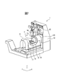
- FIG. 2 shows a schematic perspective view of the machine tool in the present embodiment.
- the machine tool 1 is a table turning type in which a work is turned together with a table 16.
- the machine tool 1 has an X axis, a Y axis, and a Z axis that are orthogonal to each other.
- an A axis is set as a rotation feed axis around an axis extending in parallel with the X axis.
- a C-axis is set as a rotation feed axis around an axis extending in parallel with the Z-axis.
- the machine tool 1 includes a bed 11 as a base and a column 12 standing on the upper surface of the bed 11.
- the machine tool 1 includes a spindle head 14 that rotatably supports the spindle 13 and a saddle 15 that supports the spindle head 14 in front of the column 12.
- the spindle head 14 supports the spindle 13 downward so that the tip of the spindle 13 faces the table 16.
- a tool is attached to the tip of the main shaft 13.
- the machine tool 1 includes a table 16 on which a workpiece is arranged and a U-shaped swing support member 18 that supports the table 16.
- the machine tool 1 includes a U-shaped carriage 17 that supports a swing support member 18.
- the carriage 17 supports the swing support member 18 with a pair of support posts spaced apart in the X-axis direction.
- the swing support member 18 is supported so as to be swingable about the axis of the A axis.
- the machine tool 1 includes a moving device that moves the tool relative to the workpiece based on each feed axis.
- the moving device includes each axis servo motor 75 driven along each feed axis.
- the moving device moves the saddle 15 with respect to the column 12 in the Y-axis direction.
- the moving device moves the carriage 17 in the X-axis direction with respect to the bed 11.
- a cavity 12c is formed so that the carriage 17 can partially enter.
- the moving device moves the spindle head 14 in the Z-axis direction with respect to the saddle 15.
- the moving device rotates the table 16 around the axis of the C axis. Further, the moving device rotates the swing support member 18 around the axis of the A axis with respect to the carriage 17.
- the machine tool 1 has three linear motion axes, that is, an X axis, a Y axis, and a Z axis, which are orthogonal to each other, and two rotating feed axes, which are an A axis and a C axis.
- the machine tool may have other forms.
- the machine tool may be a spindle turning type having an A axis and a C axis on the spindle side.
- the machine tool may be a mixed type having a C-axis on the table side and an A-axis on the main shaft side, even if the main shaft has a horizontal shape, or does not have a rotary feed shaft. I do not care.
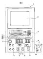
- FIG. 3 shows a schematic front view of the operation panel arranged in the control device of the machine tool.
- operation panel 41 includes a manual input unit 29 and a display unit 28 of control device 70.
- the operation panel 41 includes a display panel 45 as the display unit 28.
- the display panel 45 of the present embodiment is a touch panel system.
- the display panel 45 also functions as the operation unit 30.
- a pointing device such as a mouse, a joystick, or a touch pad may be employed instead of the touch panel type display unit.
- the operation panel 41 includes a keyboard unit 42. By pressing a key switch of the keyboard unit 42, a predetermined number or character can be input.
- the operation panel 41 includes an operation switch unit 44 that selects a predetermined operation.
- the operation panel 41 includes jog buttons 46a and 46b for manually driving the machine tool in the positive direction or the negative direction, and an override setting unit 43 for setting an override value.
- the operation panel 41 includes buttons such as an emergency stop button 48 that immediately stops when the machine tool is abnormal and an execution button 47 that starts driving the machine tool.
- a manual pulse generator 40 is connected to the operation panel 41.
- the manual pulse generator 40 is formed in a small size so that it can be operated while being held by an operator.
- the manual pulse generator 40 is provided with an axis selection button 40b for selecting a feed axis to be driven and a dial 40a for adjusting a pulse generation amount.
- the keyboard unit 42, the operation switch unit 44, the override setting unit 43 and various buttons arranged on the operation panel 41 function as the manual input unit 29 of the operation unit 30.
- the manual pulse generator 40 also functions as the manual input unit 29 of the operation unit 30.
- the operation switch unit 44 When operating the machine tool, the operator selects the operation mode of the machine tool.
- the operation switch unit 44 is provided with operation mode selection buttons 49a to 49d for selecting the operation mode of the machine tool.
- the operator sets the type of work in the machine tool as the operation mode.
- the operation mode of the machine tool can be switched by pressing desired operation mode selection buttons 49a to 49d.
- the machine tool when editing the machining program, the machine tool is set to the edit mode by pressing the operation mode selection button 49a.
- the machine tool is driven based on the machining program, the machine tool is set to the execution mode by pressing the operation mode selection button 49b.
- the machine tool is set to the manual operation mode by pressing the operation mode selection button 49c.
- the machine tool control device 70 of the present embodiment can display a three-dimensional image of the machine tool on the display panel 45. That is, a three-dimensional image can be displayed on the display panel 45.
- the image of the machine tool includes an image of the auxiliary device 33 in addition to the workpiece and the tool.
- preparation work for displaying a three-dimensional image on the display panel 45 will be described.
- model data 39 for displaying a three-dimensional image is input to the information control unit 20.
- the model data 39 can be generated from a solid model.
- the model data 39 includes model data relating to the shape of the machine tool.
- information on the auxiliary device 33 such as a tool changer can be included in the model data of the machine tool.
- the machine tool model data can be previously input to the information control unit 20 by the manufacturer of the machine tool and stored in the storage unit 26.
- the model data 39 includes model data relating to the shape of the workpiece.
- the workpiece model data includes workpiece model data before machining. That is, material model data is included.
- the workpiece model data includes workpiece model data after machining.
- the workpiece model data can be generated by a CAD device or a CAM device 77, for example.
- the model data of the workpiece includes information on the position arranged on the table 16 of the machine tool 1 in addition to information on the shape of the workpiece. When the information on the position of the workpiece in the table 16 is not included, the workpiece is set to be arranged at the center of the table 16.
- the workpiece model data can include the workpiece attachment model data.
- model data 39 includes model data relating to the shape of the tool.
- model data of the tool model data supplied by the tool manufacturer can be used.
- the workpiece model data and tool model data can be input to the information control unit 20 by an operator and stored in the storage unit 26.
- a part of the machine tool 1 can be designated by an image of the machine tool displayed on the display unit 28 as will be described later.
- the display control unit 22 detects the pressed position of the display panel 45 and specifies the part of the machine tool selected by the operator based on the pressed position.
- the table 16 can be selected by pressing the image of the table 16 of the machine tool 1 with a finger.
- FIG. 4 shows a schematic perspective view for explaining the calibration of the position of the workpiece on the table.
- the position of the workpiece W before calibration is indicated by a one-dot chain line.
- the position of the workpiece W after calibration is indicated by a solid line.
- a workpiece coordinate G54 stored in the machine tool based on the workpiece model data is shown.
- the reference point 301 of the workpiece W is displaced from the origin position of the workpiece coordinates G54.
- calibration is performed so that the reference point 301 of the workpiece W overlaps the origin of the workpiece coordinates G54, as indicated by the arrow 201.
- the actual workpiece W arranged on the table 16 is moved.
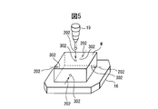
- FIG. 5 is a schematic perspective view for explaining the measurement for calibrating the position of the work placed on the table.
- the position detection device 34 includes a touch probe 19.
- a rectangular parallelepiped work W before processing is arranged on the table 16.
- a plurality of measurement points 302 are set at a substantially central portion of each surface of the workpiece W. Then, as indicated by an arrow 202, the tip of the touch probe 19 is brought into contact with a plurality of measurement points 302.
- the arithmetic processing unit 25 of the information control unit 20 detects the coordinate value at this time. That is, the arithmetic processing unit 25 detects the coordinate values of the plurality of measurement points 302.
- the arithmetic processing unit 25 calculates the coordinate value of the reference point 301 of the workpiece W using the coordinate values of the plurality of measurement points 302. Then, the arithmetic processing unit 25 calculates a deviation amount between the reference point 301 and the origin of the work coordinates G54.
- the operator can adjust the position of the workpiece W on the table 16 as indicated by an arrow 201 based on the calculated deviation amount. An operator can adjust using a dial gauge etc., for example. In this way, calibration that matches the position of the actual workpiece W with the position of the workpiece model data can be performed.
- the calibration of the workpiece position is not limited to this form, and the workpiece position on the table in the model data may be calibrated.
- the position of the origin of the workpiece coordinates G54 may be moved based on the actual measurement result of the workpiece.
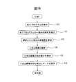
- FIG. 6 shows a flowchart for calibrating the position of the workpiece in the present embodiment.
- operation processing unit 25 reads model data 39. In this state, the position of the work on the table in the model data is shifted from the position of the work placed on the actual table.
- step 132 the display control unit 22 displays a three-dimensional image on the display unit 28 based on the model data.
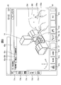
- Fig. 7 shows an image displayed on the display unit when measuring a workpiece.
- a first manual operation screen 60a as an auxiliary screen is displayed on the main screen.
- the manual operation screen 60a is a screen for inputting operation of the machine tool or displaying the state of the machine tool when the machine tool is operated manually.
- the screen displayed by pressing the selection units 51a to 51e is a screen that is frequently used in actual processing, and is referred to as a main screen in the present embodiment.
- the program editing screen can be displayed by pressing the program editing selection unit 51a among the selection units 51a to 51e.
- the program edit screen is a screen for creating and displaying a machining program for machining a workpiece.
- a tool information screen for inputting, displaying, and editing information about the tool can be displayed.
- a coordinate information screen for inputting, displaying, and editing coordinate information can be displayed.
- a screen showing the state of the machine tool that is executing the program is displayed.
- the selection unit 51e the measurement result of the workpiece after processing is displayed.
- the operator presses the operation mode selection button 49c to set the operation mode of the machine tool to the manual operation mode.
- the manual operation screen 60a includes selection units 62a to 62c.
- the selection unit 62a is selected when the workpiece, tool, or auxiliary device is manually driven.
- the selection unit 62b selects when a predetermined surface is directed to the tool.
- the selection part 62c selects when measuring the coordinate value of the arbitrary points of a workpiece
- the spindle head 14, the tool T, the table 16, and the workpiece W arranged on the table 16 are displayed as a three-dimensional image.
- the operator can designate a measurement point 302 for calibrating the position of the workpiece on the table in the three-dimensional image.
- the display control unit 22 of the present embodiment can enlarge or reduce a three-dimensional image.
- the display control unit 22 can move the three-dimensional image in a desired direction. For example, it is possible to change the display part by moving the image linearly or to change the display direction by rotating the image.
- step 133 the operator designates measurement point 302 in the three-dimensional image.
- the operator presses a button 61 a for designating a measurement point arranged in the button area 61. After this, the operator presses the measurement point 302 portion of the image with his / her finger to display the mark 99 of the measurement point 302.
- the display control unit 22 detects the position of the measurement point 302. The operator changes the direction of the three-dimensional image and designates all the measurement points 302.
- the program creation unit 21 creates a measurement program.
- the program creation unit 21 creates a measurement program in which the touch probe 19 moves with respect to a plurality of measurement points 302 as indicated by arrows 202. That is, a measurement program for moving the table 16 and the spindle head 14 is created so that the tip of the touch probe 19 contacts the measurement point 302.
- step 135 the workpiece is measured. That is, referring to FIG. 3, when the operator presses the execution button 47 of the operation panel 41, the measurement of the coordinates of the measurement point 302 is automatically started.
- information control unit 20 sends the created measurement program to reading interpretation unit 72.
- the spindle head 14 moves toward the workpiece W.
- the touch probe 19 gradually moves from a position away from the measurement surface toward the measurement point 302.
- work measuring apparatus 35 detects that the front-end
- the arithmetic processing unit 25 detects a coordinate value when the tip of the touch probe 19 comes into contact.
- the coordinate value can be detected by the position detection device 34. For example, the machine coordinate value of each measurement point 302 can be detected.
- step 136 the arithmetic processing unit 25 calculates the coordinate value of the reference point 301 of the actual workpiece W based on the coordinate values of the plurality of measurement points 302. Further, the arithmetic processing unit 25 calculates a deviation amount between the actual position of the workpiece W and the position of the workpiece in the model data. Then, the display control unit 22 displays the coordinate value and deviation amount of the reference point 301 of the actual work W on the display unit 28.
- step 137 the actual position of the workpiece W is adjusted to the position in the workpiece model data.
- the operator adjusts the position of the workpiece W on the actual table 16.
- the workpiece position can be calibrated.
- a three-dimensional image of the workpiece can be accurately displayed on the display unit.
- the control device can correctly recognize the designated part in the actual work.
- the workpiece dimensions can be measured in addition to the workpiece position calibration by the same operation as described above.
- a probe can be brought into contact with a predetermined portion of the processed workpiece, and the dimension of the processed workpiece can be measured.
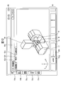
- FIG. 8 shows a second manual operation screen in the embodiment.
- the operator can display the auxiliary screen of the viewpoint switching button by pressing the display switching button 61b.
- On this auxiliary screen it is possible to select from which viewpoint the displayed three-dimensional image of the machine tool is displayed.
- the operator selects a desired viewpoint from the auxiliary screen, and displays an image of the machine tool viewed from the viewpoint on the screen.
- the image and the actual feed axis of the machine tool can be driven in a desired direction with respect to the selected feed axis.
- a desired feed axis is selected by the axis selection button 40b. Then, the selected feed shaft can be driven in a desired direction by turning the dial 40a.
- the control device 70 can manually drive the machine tool by the operator operating a three-dimensional image displayed on the display panel 45.
- the storage unit 26 stores in advance the operation of the machine tool corresponding to the operator's operation on the image of the machine tool.
- the control device 70 acquires the operation content of the operator with respect to the image of the machine tool, and generates an operation command for driving the machine tool corresponding to the operation content.
- the machine tool is driven based on the operation command.
- the selection unit 62a is selected on the manual operation screen 60b.
- the display switching button 61b shown in the button area 61 is pressed, a list of parts to be displayed is displayed.
- the table 16 and the spindle head 14 are displayed by selecting the table and the spindle head portion.
- the image By moving a region in which no image of the machine tool is displayed with the finger 105a in a desired direction indicated by an arrow 203, the image is moved linearly within the screen, or the back side is displayed facing forward. It can be rotated. For example, when the screen is moved while touching the screen with two fingers, the image moves linearly, and when the screen is moved while touching the screen with one finger, the screen rotates.
- the displayed part can be enlarged by pushing the area where the image of the machine tool is not displayed with two fingers to widen the distance between the fingers.
- the image can be reduced by narrowing the interval between two fingers. Since the three-dimensional image can be enlarged, reduced, linearly moved, and rotated, a desired part of the machine tool or the workpiece can be easily seen. For example, when a recess is formed in the workpiece, the shape inside the recess can also be confirmed.
- the display control unit 22 recognizes the movement of the finger after pressing the display panel 45 with the finger, and moves or enlarges the image.
- the display panel 45 of the present embodiment can display a desired portion from a desired angle.
- the display unit can display a desired portion at a desired magnification.
- the direct mode is an operation mode in which an image is moved with a finger and an actual machine tool is driven according to the image.
- the button area 61 the button 61c in the direct mode is pressed for selection.
- the carriage 17 is moved to the positive side of the X axis.
- the linear motion axis button 61e is selected.
- the carriage 17 is selected by pushing with the finger 105b.
- the finger 105b is moved in the direction indicated by the arrow 204 while keeping the carriage 17 pressed.
- FIG. 9 shows a third manual operation screen in the present embodiment.
- FIG. 9 is a manual operation screen 60 b after the carriage 17 is moved in the direction indicated by the arrow 204.
- the spindle head 14 does not move, but the carriage 17 moves.
- the carriage 17 is moved to the positive side of the X axis.
- the actual moving amount of the machine tool at this time corresponds to the moving amount on the screen. That is, the larger the predetermined part is moved on the screen, the larger the corresponding part of the actual machine tool is moved.
- the actual moving speed may correspond to the moving speed of the finger. Control that increases the actual moving speed as the moving speed of the finger increases may be performed.
- the button 61f of the rotation axis in the button area 61 is selected. Then, the part to be rotated can be rotated by moving with the finger and moving the finger in the direction of rotation while maintaining the pressed state with the finger. For example, by moving the finger in a desired rotation direction while pushing the swing support member 18, the swing support member 18 can be rotated in the A-axis direction in the image of the machine tool and the actual machine tool.
- the portion displayed on the screen can be moved in the direction of the feed axis.
- the actual machine tool can be driven manually. Since the operator can drive the machine tool intuitively while viewing the three-dimensional image, the operator can easily drive the machine tool. Moreover, erroneous operation can be suppressed. For example, it is possible to prevent the workpiece or tool from moving in the opposite direction to the desired direction.
- Fig. 10 shows a flowchart of control when the machine tool is driven manually in the direct mode.
- display control unit 22 displays a three-dimensional image on display unit 28.
- the display control unit 22 acquires the operation content of the operator in the three-dimensional image. For example, the display control unit 22 acquires that a predetermined point of a three-dimensional image has been pressed.
- the display control unit 22 detects the part of the machine tool selected with the finger. Then, the display control unit 22 detects that the pressed portion moves in a predetermined direction at a predetermined time.
- the display control unit 22 detects the moving direction and moving distance of the pressed part. As the finger moving direction, the direction of rotational movement along a predetermined rotational feed axis or the direction of linear movement along a predetermined linear motion axis is detected.
- step 143 the display control unit 22 displays an image of the moving machine tool.
- the display control unit 22 moves the image displayed on the display unit 28 according to the movement of the finger.
- step 144 the program creation unit 21 creates a movement program for moving the part selected with the finger.
- the arithmetic processing unit 25 calculates the movement amount in the corresponding feed axis direction based on the movement direction and movement amount of the finger. The movement amount is calculated so that the movement amount in the image corresponds to the actual movement amount of the machine tool.
- the program creation unit 21 creates a movement program based on the selected feed axis and the calculated movement amount. As described above, the program creation unit 21 creates a movement program for instantaneously moving a selected portion of the machine tool.
- step 145 the information control unit 20 sends the moving program to the reading interpretation unit 72.
- Each axis servo motor 75 is driven by the servo control unit 74.
- the machine tool 1 moves the selected portion in the direction of the predetermined feed axis, similarly to the movement of the image displayed on the display unit 28.
- the selection of the feed axis, the feed direction and the feed amount according to the operation of the operator's screen are changed to the axis selection button 40b and dial 40a of the manual pulse generator 40. May be converted into a signal in the direction of turning and a pulse generation amount signal and sent to the servo control unit 74.
- step 146 it is determined whether or not the operator's operation on the image is completed.
- the arithmetic processing unit 25 determines whether or not the movement of the portion pressed on the display unit 28 has been completed. That is, it is determined whether or not the movement of the finger has stopped or the finger has left the screen.
- the process returns to step 142 to continue the movement of the image and the driving of the machine tool.
- this control is finished. By repeating this control in a short time, the machine tool can be continuously driven according to the image.
- the arithmetic processing unit 25 calculates whether the model data of the machine tool moving with each other, the model data of the tool, and the model data of the workpiece do not interfere with each other. When the interference occurs, the movement of the image on the screen is stopped and the feed axis of the machine tool is stopped. Since the interference check is performed in this way, even if the operator carelessly operates the image, the tool and the workpiece do not collide and the feed shaft does not exceed the stroke end.
- the normal mode among the manual operation modes will be described.
- the portion selected in the image is moved, and the movement state including the feed axis and the movement amount is stored in the storage unit 26.
- the machine tool is stopped.
- the stored movements are performed at once.
- the spindle head 14 is moved to the positive side of the Z axis after the carriage 17 is moved to the positive side of the X axis is illustrated.
- the normal mode button 61d is selected.
- the finger 105b is moved to move the carriage 17 on the image.
- the carriage 17 moves in the image, but the carriage 17 is stopped in the actual machine tool.
- the spindle head 14 is pushed with the finger 105b to move to the positive side of the Z axis.
- the spindle head 14 moves to the positive side of the Z axis, but the spindle head 14 of the actual machine tool is stopped.
- the selected part of the machine tool moves according to the order of movement in the image.
- the feed axis and the moving amount of the portion where the storage unit 26 moves are stored.
- storage part 26 may memorize
- the program creation unit 21 creates a movement program corresponding to the operation of the worker.
- the execution button 47 the information control unit 20 sends the movement program to the reading / interpretation unit 72, and each axis servo motor 75 is driven.
- the feed axis and the movement amount corresponding to the movement direction in the image of the machine tool are set.
- An operation command for the machine tool is generated based on the movement amount of the feed axis.
- a moving program is created according to the operator's screen operation. Then, the machine tool can be driven in accordance with the image by driving the moving device of each feed shaft based on the moving program.
- a predetermined surface of the workpiece may be directed in a desired direction.
- a predetermined surface of a workpiece is directed to a tool and a hole is drilled on this surface.
- index control for adjusting the orientation of the workpiece so that a predetermined surface of the workpiece is perpendicular to the axis of the main shaft is exemplified.
- FIG. 11 shows a fourth manual operation screen in the present embodiment.
- the index selection unit 62b is selected.
- the manual operation screen 60c an image in which the workpiece W before processing is arranged on the table 16 is displayed.
- the surface on which the workpiece W is to be indexed can be selected by pressing the surface designation button 61g in the button area 61.
- the operator rotates or enlarges the image as necessary and presses a desired surface with a finger.
- the selected surface is referred to as a designated surface.
- the designated surface is emphasized so that it can be distinguished from other surfaces, for example. In the example shown in FIG. 11, the selected surface is hatched.
- the execution button 47 on the operation panel 41 the specified surface can be indexed.
- the image displayed on the display unit 28 moves and the machine tool is driven.
- the swing support member 18 rotates in the A-axis direction
- the table 16 further rotates in the C-axis direction.
- FIG. 12 shows a fifth manual operation screen after indexing.
- the manual operation screen 60c is a screen after the image displayed on the display panel 45 has moved.
- the table 16 is rotated 90 ° in the Z-axis direction, and the swing support member 18 is rotated 90 ° in the A-axis direction.
- the specified surface is perpendicular to the axis of the main axis.
- An actual machine tool is also operated in the same manner as a three-dimensional image.
- display control unit 22 acquires a designated surface of a work selected by an operator in an image.
- the arithmetic processing unit 25 acquires the current orientation and angle of the designated surface based on the workpiece model data. Further, the arithmetic processing unit 25 acquires the current position of the feed axis from the position detection device 34.
- the arithmetic processing unit 25 calculates the amount of movement of the feed axis so that the designated surface becomes perpendicular to the axis of the spindle. At this time, for the rotation feed shaft, the rotation angle of the rotation feed shaft is calculated.
- the display control unit 22 displays an image in which the machine tool is driven along the selected feed axis.
- the program creation unit 21 creates a movement program for driving the machine tool.
- the movement program created by the program creation unit 21 is sent to the reading / interpretation unit 72.
- each axis servo motor 75 is driven, and the specified surface can be indexed.
- the control device 70 acquires the operation content in which one surface of the workpiece is selected as the designated surface by the operator, and calculates the rotation angle of the rotary feed shaft for directing the designated surface in a predetermined direction. An operation command for rotating the table based on the rotation angle is generated. Since the control device 70 can designate a designated surface with a three-dimensional image, it can easily designate a designated surface to be indexed. Further, it is not necessary to calculate a complicated rotation angle, and a desired surface can be easily indexed.
- an animation button 61 h is arranged in the button area 61 on the manual operation screen 60 c of the present embodiment.
- the animation button 61h By pressing the animation button 61h after selecting the designated surface, the image moves and the operation of the machine tool can be confirmed.
- the machine tool can confirm the state of movement with a three-dimensional image while maintaining the stopped state. For this reason, the presence or absence of an abnormality can be confirmed with a three-dimensional image. For example, it can be confirmed in advance that the tool T does not interfere with the workpiece W. After that, the designated surface can be indexed by pressing the execution button 47 of the operation panel 41.
- the surface perpendicular to the workpiece mounting surface of the table 16 is the designated surface of the workpiece, but an inclined surface that is not parallel or perpendicular to the workpiece mounting surface can be designated.
- the machine tool 1 of the present embodiment is a table turning type having an A axis and a C axis on the table 16 side.
- the spindle side can be rotated along the A axis or the C axis so that the axis of the spindle is perpendicular to the designated surface. .
- both the spindle side and the table side can be rotated to make the axis of the spindle perpendicular to the specified surface.
- the control for directing the designated surface selected by the operator toward the main axis has been described.
- the present invention is not limited to this configuration, and can be applied to control for directing the designated surface in a predetermined direction.
- the control device can be formed so that the direction in which the designated surface is directed can be set.
- FIG. 13 shows a sixth manual operation screen in the present embodiment.
- the tool or workpiece is moved by operating the manual operation screen.
- the auxiliary device 33 provided in the machine tool can be moved by operating the manual operation screen 60d.
- a tool changer is illustrated as an example of the auxiliary device 33.
- the tool changer is selected from the menu displayed by pressing the display switching button 61b.
- the tool changer according to the present embodiment includes a tool magazine 93 that stores a plurality of tools T, an exchange arm 96 that attaches and removes a tool to and from the spindle, and a tool between the tool magazine 93 and the exchange arm 96. And a transfer device 94 for transferring the.
- a plurality of tools are arranged in the tool magazine 93.
- the position of the tool T1 is an exchange position for taking out the tool from the tool magazine 93 and storing the tool in the tool magazine 93.
- the operator moves to the replacement position as indicated by an arrow 205 along the direction in which the tool magazine 93 extends while maintaining the state in which the tool T2 is pressed with a finger.
- the tool magazine 93 is rotated, and the tool T2 can be arranged at the replacement position.
- the movement amount of the tool magazine 93 is determined according to the movement amount of the finger.
- the type of tool arranged in the tool magazine 93 can be confirmed.
- the tool arranged at the exchange position can be manually moved to the exchange arm 96. Even when the auxiliary device 33 is driven, the direct mode or the normal mode can be selected by the buttons 61c and 61d.
- the display control unit 22 acquires the operation content of the operator's image.
- the arithmetic processing unit 25 calculates the movement amount.
- the operation command generation unit 27 of the auxiliary device sends an operation command according to the operation of the worker to the auxiliary device control unit 32.
- the auxiliary device control unit 32 operates the auxiliary device 33 based on the operation command.
- the control device 70 of the present embodiment is configured to operate the auxiliary device without using a program.
- the specified portion of the auxiliary device 33 can be started and stopped.
- a cooling liquid supply device will be described as an example of the auxiliary device 33.
- FIG. 14 shows a seventh manual operation screen in the present embodiment.
- the coolant supply device is selected from the menu list displayed by pressing the display switching button 61b.
- the coolant supply apparatus of the present embodiment includes a tank that stores coolant, a pump, and a coolant jet nozzle 95.
- the tip portion of the spindle head 14 is enlarged and displayed.
- a coolant jet nozzle 95 is disposed at the tip of the spindle head 14.
- the coolant supply device By pushing the coolant jet nozzle 95, the coolant supply device can be started and the coolant can be jetted from the coolant jet nozzle 95.
- it is possible to stop the ejection of the coolant by pushing the coolant ejection nozzle 95 while the coolant is being ejected.
- the auxiliary device when the auxiliary device is operated, the auxiliary device is highlighted and displayed so that the operating state of the auxiliary device becomes clear. In this example, the color of the coolant jet nozzle 95 changes.
- an image indicating whether the auxiliary device is driven or stopped may be displayed so that the state where the auxiliary device is driven or stopped is clear.
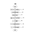
- FIG. 15 shows a flowchart of control when starting or stopping the auxiliary device.
- display control unit 22 displays a three-dimensional image of the part selected by the operator on display unit 28.
- step 152 the display control unit 22 detects that a predetermined auxiliary device 33 has been pressed in the image. That is, the display control unit 22 detects that the operator has selected the predetermined auxiliary device 33.
- step 153 the arithmetic processing unit 25 determines whether or not the selected auxiliary device 33 is stopped.
- step 153 when the auxiliary device 33 is stopped, the process proceeds to step 154.
- step 154 the auxiliary device 33 is activated.
- step 153 when the auxiliary device 33 is operating, the process proceeds to step 155.
- step 155 the auxiliary device 33 is stopped.
- step 156 the operating state of the auxiliary device is displayed. In the present embodiment, the display control unit 22 changes the color of the auxiliary device 33 according to the operating state or the stopped state.
- the operation command generation unit 27 of the information control unit 20 sends the operation command to the auxiliary device control unit 32.
- a program for moving the auxiliary device 33 may be created.
- the program creation unit 21 can create a program including M code for ejecting the coolant from the coolant jet nozzle 95.
- the program creation unit 21 generates a program based on the operator's image operation and sends it to the reading interpretation unit 72.
- the reading interpretation unit 72 sends an operation command for the auxiliary device 33 to the auxiliary device control unit 32.
- the auxiliary device control unit 32 drives the auxiliary device 33 based on the operation command.
- command codes such as G codes and M codes are frequently used. Based on the command code, the tool is moved relative to the workpiece or the auxiliary device is controlled.
- the machining program may be modified after confirming the machining result. Or, there is a case where it is desired to check which part of the workpiece is processed by the command code.
- the command code there are many command codes, and it is difficult for an operator to remember all the command code numbers. For this reason, in the prior art, the worker has been searching for a corresponding part by relying on memory. Or the worker was looking for the applicable location, referring to a reference. For this reason, workers are required to have advanced knowledge and judgment. In addition, it may take time or errors may occur.
- the position of the machining program can be specified while viewing a three-dimensional image, and the part to be machined can be specified based on the command code of the machining program.
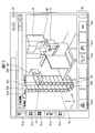
- FIG. 16 shows a first program editing screen displayed on the display panel of the operation panel.
- the creation of the program according to the present embodiment includes a case where a new program is created and a case where a program that has already been created is edited to create this program.
- an operation mode selection button 49a for setting the edit mode is pressed with reference to FIG.
- the program editing screen 55a is displayed by pressing the selection unit 51a.
- the program edit screen 55a of the present embodiment includes a display area 81a and a display area 81b.
- a machining program is displayed in the display area 81a.
- a machining program can be created.
- a plurality of selection sections 85a and 85b are arranged. The user can select a machining program to be created by pressing one of the selection units 85a and 85b.
- the selection unit 85b is selected.
- buttons 59a arranged in the button area 59 information displayed in the right display area 81b can be selected.
- a three-dimensional image of the processed workpiece is displayed in the display area 81b.
- a desired portion of the image displayed in the display area 81b can be selected by pressing with a finger.
- the corresponding part of the processing program for processing the selected image portion can be displayed.
- one hole portion 103a is selected in the workpiece image in the display area 81b.
- the corresponding part of the machining program is displayed in the display area 81a.
- a mark 103b is displayed in the corresponding part.
- a mark 103b indicates a command code for processing the hole portion 103a of the workpiece.
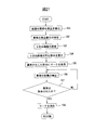
- FIG. 17 shows a flowchart of control for selecting a desired part of the three-dimensional image and displaying the corresponding part of the machining program.
- display control unit 22 displays a machining program and a three-dimensional workpiece image on display unit 28. The operator selects a desired portion of the image by pressing it with a finger.
- the display control unit 22 detects selection of a part of the image of the workpiece. That is, the display control unit 22 detects the part of the workpiece selected by the operator.
- the arithmetic processing unit 25 calculates the coordinate value of the selected portion of the workpiece. For example, the coordinate value of the workpiece coordinate is calculated.
- the arithmetic processing unit 25 analyzes the machining program. The arithmetic processing unit 25 extracts a command code for processing the portion of the calculated coordinate value from the processing program. When there are a plurality of corresponding parts of the machining program, the last command code is selected. Alternatively, when there are a plurality of corresponding portions of the machining program, all of them may be extracted.
- step 165 the display control unit 22 displays a corresponding part of the machining program. For example, when the machining program is very long, the display range of the machining program is selected so that the corresponding part is displayed.
- step 166 the display control unit 22 displays the mark 103b for the command code of the corresponding machining program.
- control device 70 can extract a corresponding part of the machining program based on the operation of the image of the machine tool. The operator can save the trouble of searching for the corresponding part of the machining program, and can easily confirm or correct the corresponding part of the machining program.
- FIG. 18 shows a second program editing screen displayed on the display panel of the operation panel.
- the second program editing screen 55b when a command code of a desired machining program is selected in the display area 81a, an image of a portion to be machined with the selected command code is displayed in the display area 81b.
- the selected part is surrounded by a frame 104a.
- the corresponding part display button 59b By pressing the corresponding part display button 59b in the button area 59, a three-dimensional workpiece image corresponding to the selected part of the machining program is displayed in the display area 81b.
- a mark 104b is displayed in the corresponding part of the image of the machine tool.
- a three-dimensional image is displayed in a state of being enlarged or moved for easy viewing by the operator.
- FIG. 19 shows a control flowchart for displaying the part of the workpiece to be machined in the selected part of the machining program.
- display control unit 22 displays a machining program and a three-dimensional workpiece image. The operator selects a desired part of the machining program.
- the arithmetic processing unit 25 detects a selected part of the machining program.
- the arithmetic processing unit 25 calculates the coordinate value of the selected portion of the machining program. For example, the arithmetic processing unit 25 calculates a work coordinate value.
- the arithmetic processing unit 25 performs a three-dimensional image analysis. The arithmetic processing unit 25 identifies a corresponding part of the three-dimensional image based on the calculated coordinate value.
- step 175 the display control unit 22 displays a corresponding portion of the three-dimensional image.
- the display control unit 22 displays the workpiece image in an enlarged or moved state so that the corresponding portion can be easily seen.
- step 176 the display control unit 22 displays the mark 104b on the corresponding part of the image.
- control device 70 can easily identify the part of the workpiece to be machined in one part of the machining program. For this reason, it is possible to easily check the machining program and correct an error.
- an image of the auxiliary device is displayed, and a command code for starting and stopping the auxiliary device is automatically inserted into the machining program by pressing the image of the auxiliary device. Can do.
- the operator does not need to learn command codes and arguments related to the auxiliary device, and can easily create a machining program. In addition, erroneous operations such as command code input errors can be reduced.
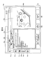
- FIG. 20 shows a diagnostic screen for displaying the state of the machine tool.
- the diagnosis screen 63 is an auxiliary screen displayed so as to overlap the main screen.
- An information display area 86 is set at the top of each main screen.
- the operation state detection device 36 detects the operation state of the machine tool in each operation mode.
- the arithmetic processing unit 25 determines whether or not the operating state of the machine tool 1 matches a predetermined condition.
- the display control unit 22 acquires the determination result and displays an icon corresponding to the state of the machine tool 1 in the information display area 86.
- the icon image is stored in the storage unit 26 in advance.
- an abnormality has occurred in the tool measurement device during the measurement of the tool, and the measurement of the tool is interrupted.
- the arithmetic processing unit 25 determines that an abnormality has occurred in the tool measuring device 92 based on a signal from the operating state detection device 36.
- the display control unit 22 displays a warning icon 86 a in the information display area 86.
- the display control unit 22 displays a diagnosis screen 63 including information related to warnings and notifications of the machine tool 1.
- the display control unit 22 first displays a three-dimensional image in the display area 87a. At this time, an image including a portion where an abnormality has occurred is displayed.
- the display control unit 22 displays the machine tool from the direction in which the portion where the abnormality has occurred is displayed. In the example shown in FIG. 20, the image which looked at the table 16 and the spindle head 14 from the back side is displayed. Then, the display control unit 22 displays the mark 100 over the tool measuring device 92 that causes the warning. Further, the display control unit 22 blinks the mark 100 and displays it so that the operator can easily understand the abnormal part.
- the display control unit 22 displays the display areas 87b and 87c on the machine tool image.
- the type of warning is displayed in the display area 87b.
- the display area 87c displays details of the warning such as the cause of the warning and the recovery method.
- control device displays the portion where the warning is generated as a three-dimensional image
- the operator can intuitively recognize the abnormal portion.
- the operator can easily confirm detailed information regarding the warning by pressing the mark 100 displayed at the abnormal location.
- the explanation is given by taking as an example a warning when an abnormality occurs in the machine tool.
- the present embodiment is not limited to this, and a notification of the state of the machine tool may be used.
- it may be a notification that the repair time of the machine tool has come.
- ⁇ ⁇ ⁇ Marks that display locations related to warnings and notifications such as abnormal locations can be displayed with different display formats depending on the importance. For example, when the operation cannot be continued due to a machine tool breakage or the like, the red mark can be made to blink further. In the case of a light warning that can continue operation, it can be lit in a yellow mark. In the case of notification of the repair time of the machine tool, it can be lit in a blue mark.
- FIG. 21 shows a flowchart of control for displaying an alarm or notification.
- operating state detection device 36 detects the operating state of a predetermined part of the machine tool.
- the arithmetic processing unit 25 detects that an abnormality has occurred in the operating state.
- the arithmetic processing unit 25 identifies the part where the abnormality has occurred.
- step 183 the display control unit 22 selects a three-dimensional image.
- the type of image displayed when an abnormality occurs is stored in the storage unit 26 in advance. For example, when an abnormality occurs in the tool measuring device 92, an image including the carriage 17 and the spindle head 14 including the image of the tool measuring device 92 is selected.
- step 184 the display control unit 22 displays a three-dimensional image.
- the display control unit 22 selects and displays the display direction so that the part where the abnormality has occurred is easy to see from the operator.
- step 185 the display control unit 22 specifies the position on the image of the part where the abnormality has occurred. And the display control part 22 displays a mark in the part in which abnormality occurred in the image of the machine tool.
- control device 70 continuously checks whether or not the abnormality that has occurred has been resolved.
- the operator can eliminate the cause of the abnormality by looking at the diagnosis screen 63.
- the arithmetic processing unit 25 receives a signal indicating the operation state of the machine tool from the operation state detection device 36. And the arithmetic processing part 25 discriminate
- step 187 the arithmetic processing unit 25 determines whether or not the apparatus abnormality has been resolved. If the apparatus abnormality is not removed, the process returns to step 186. That is, the determination of the presence or absence of abnormality is continued. In step 187, if the apparatus abnormality is removed, the process proceeds to step 188. In step 188, the mark 100 displayed on the diagnosis screen 63 is deleted. Also, the icon 86a displayed in the information display area 86 on the main screen is deleted.
- control device of the present embodiment automatically monitors the presence or absence of abnormality removal.
- the control when the abnormality is removed is not limited to this form, and any control can be employed.
- a reset button is provided in the button area of the diagnostic screen. When the abnormality is removed, the alarm or notification can be canceled by pressing the reset button.
- the machine tool of the present embodiment is a 5-axis control machine tool, but is not limited to this form, and the present invention can be applied to a machine tool having an arbitrary feed axis.
- the image of the machine tool displayed on the display unit of the present embodiment is a three-dimensional image based on a three-dimensional solid model, but may be a surface model or a wire frame model. Moreover, it is not restricted to these forms, A two-dimensional planar image may be sufficient.
Abstract
Description
14 主軸頭
16 テーブル
20 情報制御部
21 プログラム作成部
22 表示制御部
25 演算処理部
26 記憶部
27 動作指令生成部
28 表示部
33 補助装置
34 位置検出装置
36 運転状態検出装置
41 操作盤
45 表示パネル
55a,55b プログラム編集画面
60a~60e 手動運転画面
70 制御装置
75 各軸サーボモータ
76 加工プログラム
92 工具測定装置
93 工具マガジン
95 冷却液噴出ノズル
W ワーク
T,T1,T2 工具
Claims (6)
- 工具とワークとを相対的に移動させてワークを加工する工作機械の制御方法であって、
工作機械の画像を表示部に表示し、
工作機械の画像に対する作業者の操作に対応する工作機械の動作を予め記憶し、
工作機械の画像に対する作業者の操作内容を取得し、
前記操作内容に対応して工作機械が動作するための動作指令を生成し、
前記動作指令に基づいて工作機械を稼働させることを特徴とした、工作機械の制御方法。 - 前記表示部に表示する工作機械の画像は3次元の画像である、請求項1に記載の工作機械の制御方法。
- 工作機械のテーブルにワークを配置した画像を表示部に表示し、
前記操作内容は、作業者によりワークの一つの面が指定面として選択された操作であり、
前記指定面を予め定められた方向に向けるための回転送り軸の回転角度を算出し、
前記回転角度に基づいて回転送り軸を回転させる前記動作指令を生成する、請求項1に記載の工作機械の制御方法。 - 作業者により工作機械の画像の一部分を選択した状態を維持して移動させた場合に、工作機械の画像における移動方向に対応する送り軸および移動量を設定し、
前記送り軸の前記移動量に基づいて前記動作指令を生成する、請求項1に記載の工作機械の制御方法。 - 工作機械の補助装置の画像を表示部に表示し、
前記操作内容は、前記補助装置の画像に対する操作であり、
前記動作指令は、前記補助装置を動作させる指令であり、
前記動作指令に基づいて前記補助装置を稼働させる、請求項1に記載の工作機械の制御方法。 - 工具とワークとを相対的に移動させてワークを加工する工作機械の制御装置であって、
工作機械の画像を表示する表示部と、
工作機械の加工に関する情報を記憶する記憶部と、
前記表示部に表示する工作機械の画像を制御し、工作機械の画像に対する作業者の操作内容を取得する情報制御部とを備え、
前記記憶部は、工作機械の画像に対する作業者の操作に対応する工作機械の動作を記憶しており、
前記情報制御部は、前記操作内容に対応して工作機械が動作するための動作指令を生成し、
前記動作指令に基づいて工作機械を稼働させることを特徴とした、工作機械の制御装置。
Priority Applications (6)
| Application Number | Priority Date | Filing Date | Title |
|---|---|---|---|
| EP14905019.7A EP3214514B1 (en) | 2014-10-27 | 2014-10-27 | Machine tool control method and machine tool control device |
| JP2016556064A JP6351745B2 (ja) | 2014-10-27 | 2014-10-27 | 工作機械の制御方法および工作機械の制御装置 |
| US15/517,469 US20170308055A1 (en) | 2014-10-27 | 2014-10-27 | Machine tool control method and machine tool control device |
| PCT/JP2014/078519 WO2016067342A1 (ja) | 2014-10-27 | 2014-10-27 | 工作機械の制御方法および工作機械の制御装置 |
| CN201480082927.2A CN107077124B (zh) | 2014-10-27 | 2014-10-27 | 机床的控制方法以及机床的控制装置 |
| TW103141774A TWI575345B (zh) | 2014-10-27 | 2014-12-02 | Control method of working machine and control device of working machine |
Applications Claiming Priority (1)
| Application Number | Priority Date | Filing Date | Title |
|---|---|---|---|
| PCT/JP2014/078519 WO2016067342A1 (ja) | 2014-10-27 | 2014-10-27 | 工作機械の制御方法および工作機械の制御装置 |
Publications (1)
| Publication Number | Publication Date |
|---|---|
| WO2016067342A1 true WO2016067342A1 (ja) | 2016-05-06 |
Family
ID=55856737
Family Applications (1)
| Application Number | Title | Priority Date | Filing Date |
|---|---|---|---|
| PCT/JP2014/078519 WO2016067342A1 (ja) | 2014-10-27 | 2014-10-27 | 工作機械の制御方法および工作機械の制御装置 |
Country Status (6)
| Country | Link |
|---|---|
| US (1) | US20170308055A1 (ja) |
| EP (1) | EP3214514B1 (ja) |
| JP (1) | JP6351745B2 (ja) |
| CN (1) | CN107077124B (ja) |
| TW (1) | TWI575345B (ja) |
| WO (1) | WO2016067342A1 (ja) |
Cited By (9)
| Publication number | Priority date | Publication date | Assignee | Title |
|---|---|---|---|---|
| JP2017211956A (ja) * | 2016-05-27 | 2017-11-30 | ファナック株式会社 | マルチタッチジェスチャによる機械操作が可能な数値制御装置 |
| WO2018232234A1 (en) * | 2017-06-15 | 2018-12-20 | Trounson James Edmund Iii | Integrated cad/cam/cnc software machine tool and machine tool therewith |
| JP2019139558A (ja) * | 2018-02-13 | 2019-08-22 | ファナック株式会社 | 工作機械の制御装置 |
| JP2019159808A (ja) * | 2018-03-13 | 2019-09-19 | ファナック株式会社 | 制御装置、制御方法及び制御プログラム |
| JP2020198061A (ja) * | 2019-05-30 | 2020-12-10 | ファナック株式会社 | 工作機械制御装置及び工作機械 |
| WO2021161831A1 (ja) * | 2020-02-14 | 2021-08-19 | Dmg森精機株式会社 | 表示制御システム |
| JP6991396B1 (ja) * | 2020-12-28 | 2022-01-14 | 三菱電機株式会社 | 表示装置、制御システムおよび作画方法 |
| JP7179941B1 (ja) | 2021-10-01 | 2022-11-29 | Dmg森精機株式会社 | 工作機械 |
| JP7414507B2 (ja) | 2019-12-16 | 2024-01-16 | ファナック株式会社 | 制御装置、計測システム、計測方法 |
Families Citing this family (19)
| Publication number | Priority date | Publication date | Assignee | Title |
|---|---|---|---|---|
| TWI577493B (zh) * | 2014-12-26 | 2017-04-11 | 財團法人工業技術研究院 | 校正方法與應用此方法的自動化設備 |
| JP6235517B2 (ja) * | 2015-03-27 | 2017-11-22 | ファナック株式会社 | 状況に応じたプログラムの提示機能を備えた数値制御装置 |
| JP6333798B2 (ja) * | 2015-12-03 | 2018-05-30 | ファナック株式会社 | 数値制御装置 |
| US10359266B2 (en) * | 2016-04-19 | 2019-07-23 | Okuma Corporation | Position measurement method of object in machine tool and position measurement system of the same |
| US10357863B2 (en) * | 2016-04-19 | 2019-07-23 | Okuma Corporation | Error identification method of machine tool and error identification system of the same |
| JP6792975B2 (ja) * | 2016-07-25 | 2020-12-02 | Dmg森精機株式会社 | 工作機械および検知方法 |
| JP2018176320A (ja) * | 2017-04-07 | 2018-11-15 | 株式会社ディスコ | 加工装置 |
| US11215970B2 (en) | 2017-04-27 | 2022-01-04 | Mitsubishi Electric Corporation | Processing control device, machine tool, and processing control method |
| US10549397B1 (en) * | 2017-12-19 | 2020-02-04 | Haas Automation, Inc. | Dynamic conveyor control system |
| KR102068787B1 (ko) | 2018-02-05 | 2020-01-22 | 미쓰비시덴키 가부시키가이샤 | 알람 기능 설정 장치, 알람 기능 설정 시스템 및 알람 기능 설정 프로그램 |
| JP6748153B2 (ja) * | 2018-07-10 | 2020-08-26 | ファナック株式会社 | 工作機械の異常検出装置 |
| JP6856591B2 (ja) * | 2018-09-11 | 2021-04-07 | ファナック株式会社 | 制御装置、cnc装置及び制御装置の制御方法 |
| CN109143979B (zh) * | 2018-09-28 | 2020-12-25 | 浙江大学华南工业技术研究院 | 数控设备的加工控制方法、系统、可读存储介质和设备 |
| JP7022049B2 (ja) * | 2018-12-05 | 2022-02-17 | ファナック株式会社 | 認識装置、システムおよび認識方法 |
| JP6997123B2 (ja) * | 2019-02-28 | 2022-02-03 | ファナック株式会社 | 情報処理装置および情報処理方法 |
| DE102020002382A1 (de) * | 2019-05-30 | 2020-12-03 | Fanuc Corporation | Werkzeugmaschinen-steuervorrichtung und werkzeugmaschine |
| DE102020206303A1 (de) * | 2019-06-04 | 2020-12-10 | Fanuc Corporation | Werkzeugmaschinensteuerung und werkzeugmaschine |
| TWI744147B (zh) | 2020-12-24 | 2021-10-21 | 財團法人工業技術研究院 | 可動式機械的動作測試方法與控制主機 |
| CN114035511A (zh) * | 2021-10-14 | 2022-02-11 | 扬州市创信科技有限公司 | 一种图形化数控车床智能控制系统及其控制方法 |
Citations (2)
| Publication number | Priority date | Publication date | Assignee | Title |
|---|---|---|---|---|
| JP2006350602A (ja) * | 2005-06-15 | 2006-12-28 | Yushin Precision Equipment Co Ltd | 操作端末装置 |
| WO2012105026A1 (ja) * | 2011-02-03 | 2012-08-09 | 三菱電機株式会社 | 表示装置、および表示装置の動作確認方法 |
Family Cites Families (17)
| Publication number | Priority date | Publication date | Assignee | Title |
|---|---|---|---|---|
| US6816849B1 (en) * | 1998-05-26 | 2004-11-09 | Gerald B. Halt, Jr. | Advanced internet interface |
| JP4505295B2 (ja) * | 2004-09-16 | 2010-07-21 | ヤマザキマザック株式会社 | Nc加工シミュレーション方法及びnc加工シミュレーション装置 |
| DE102006043390B4 (de) * | 2006-09-15 | 2010-05-27 | Dmg Electronics Gmbh | Vorrichtung und Verfahren zur Simulation eines Ablaufs zur Bearbeitung eines Werkstücks an einer Werkzeugmaschine |
| US9442481B2 (en) * | 2008-01-09 | 2016-09-13 | Illinois Tool Works Inc. | Automatic weld arc monitoring system |
| JP5099602B2 (ja) * | 2008-01-18 | 2012-12-19 | ブラザー工業株式会社 | 数値制御装置 |
| JP5174155B2 (ja) * | 2008-05-27 | 2013-04-03 | 株式会社牧野フライス製作所 | 工作機械 |
| WO2010109536A1 (ja) * | 2009-03-27 | 2010-09-30 | 三菱電機株式会社 | 数値制御装置および当該数値制御装置の制御方法 |
| DE102009023648A1 (de) * | 2009-05-26 | 2010-12-02 | Index-Werke Gmbh & Co. Kg Hahn & Tessky | Steuerungssystem |
| JP5144784B2 (ja) * | 2011-04-11 | 2013-02-13 | ファナック株式会社 | 工作機械の工具軌跡表示装置 |
| DE102011075467A1 (de) * | 2011-05-06 | 2012-11-08 | Deckel Maho Pfronten Gmbh | Vorrichtung zum bedienen einer automatisierten maschine zur handhabung, montage oder bearbeitung von werkstücken |
| KR102086167B1 (ko) * | 2012-10-18 | 2020-03-06 | 두산공작기계 주식회사 | 공작 기계용 비쥬얼 정보를 이용한 터렛 공구 관리 방법 |
| CN103543690B (zh) * | 2013-09-12 | 2015-12-02 | 安徽省捷甬达智能机器有限公司 | 一种图形交互式数控加工方法及装置 |
| TWM469514U (zh) * | 2013-09-16 | 2014-01-01 | Syntec Inc | 具有監控功能之數值控制系統 |
| JP6144596B2 (ja) * | 2013-09-30 | 2017-06-07 | Dmg森精機株式会社 | 表示装置 |
| JP6266300B2 (ja) * | 2013-10-24 | 2018-01-24 | Dmg森精機株式会社 | 工作機械 |
| CN203894596U (zh) * | 2014-02-27 | 2014-10-22 | 电子科技大学 | 数控机床加工状态多参数在线主动监控系统 |
| JP6418763B2 (ja) * | 2014-03-19 | 2018-11-07 | Dmg森精機株式会社 | 工作機械の手動操作用シミュレーション装置 |
-
2014
- 2014-10-27 CN CN201480082927.2A patent/CN107077124B/zh active Active
- 2014-10-27 US US15/517,469 patent/US20170308055A1/en not_active Abandoned
- 2014-10-27 JP JP2016556064A patent/JP6351745B2/ja active Active
- 2014-10-27 WO PCT/JP2014/078519 patent/WO2016067342A1/ja active Application Filing
- 2014-10-27 EP EP14905019.7A patent/EP3214514B1/en active Active
- 2014-12-02 TW TW103141774A patent/TWI575345B/zh active
Patent Citations (2)
| Publication number | Priority date | Publication date | Assignee | Title |
|---|---|---|---|---|
| JP2006350602A (ja) * | 2005-06-15 | 2006-12-28 | Yushin Precision Equipment Co Ltd | 操作端末装置 |
| WO2012105026A1 (ja) * | 2011-02-03 | 2012-08-09 | 三菱電機株式会社 | 表示装置、および表示装置の動作確認方法 |
Non-Patent Citations (1)
| Title |
|---|
| See also references of EP3214514A4 * |
Cited By (18)
| Publication number | Priority date | Publication date | Assignee | Title |
|---|---|---|---|---|
| JP2017211956A (ja) * | 2016-05-27 | 2017-11-30 | ファナック株式会社 | マルチタッチジェスチャによる機械操作が可能な数値制御装置 |
| US11561528B2 (en) | 2017-06-15 | 2023-01-24 | James Edmund Trounson, III | Integrated CAD/CAM/CNC software machine tool and machine tool therewith |
| WO2018232234A1 (en) * | 2017-06-15 | 2018-12-20 | Trounson James Edmund Iii | Integrated cad/cam/cnc software machine tool and machine tool therewith |
| JP2019139558A (ja) * | 2018-02-13 | 2019-08-22 | ファナック株式会社 | 工作機械の制御装置 |
| US10666184B2 (en) | 2018-02-13 | 2020-05-26 | Fanuc Corporation | Machine tool controller |
| JP2019159808A (ja) * | 2018-03-13 | 2019-09-19 | ファナック株式会社 | 制御装置、制御方法及び制御プログラム |
| CN110275447A (zh) * | 2018-03-13 | 2019-09-24 | 发那科株式会社 | 控制装置、控制方法以及控制程序 |
| CN110275447B (zh) * | 2018-03-13 | 2021-03-09 | 发那科株式会社 | 控制装置、控制方法以及计算机可读介质 |
| JP2020198061A (ja) * | 2019-05-30 | 2020-12-10 | ファナック株式会社 | 工作機械制御装置及び工作機械 |
| JP7384584B2 (ja) | 2019-05-30 | 2023-11-21 | ファナック株式会社 | 工作機械制御装置及び工作機械 |
| JP7414507B2 (ja) | 2019-12-16 | 2024-01-16 | ファナック株式会社 | 制御装置、計測システム、計測方法 |
| WO2021161831A1 (ja) * | 2020-02-14 | 2021-08-19 | Dmg森精機株式会社 | 表示制御システム |
| JP7019114B2 (ja) | 2020-02-14 | 2022-02-14 | Dmg森精機株式会社 | 表示制御システム |
| JPWO2021161831A1 (ja) * | 2020-02-14 | 2021-08-19 | ||
| WO2022145014A1 (ja) * | 2020-12-28 | 2022-07-07 | 三菱電機株式会社 | 表示装置、制御システムおよび作画方法 |
| JP6991396B1 (ja) * | 2020-12-28 | 2022-01-14 | 三菱電機株式会社 | 表示装置、制御システムおよび作画方法 |
| JP7179941B1 (ja) | 2021-10-01 | 2022-11-29 | Dmg森精機株式会社 | 工作機械 |
| JP2023053758A (ja) * | 2021-10-01 | 2023-04-13 | Dmg森精機株式会社 | 工作機械 |
Also Published As
| Publication number | Publication date |
|---|---|
| JP6351745B2 (ja) | 2018-07-04 |
| EP3214514A4 (en) | 2018-07-25 |
| CN107077124A (zh) | 2017-08-18 |
| TWI575345B (zh) | 2017-03-21 |
| EP3214514A1 (en) | 2017-09-06 |
| JPWO2016067342A1 (ja) | 2017-06-01 |
| EP3214514B1 (en) | 2019-09-11 |
| TW201616257A (zh) | 2016-05-01 |
| CN107077124B (zh) | 2019-10-15 |
| US20170308055A1 (en) | 2017-10-26 |
Similar Documents
| Publication | Publication Date | Title |
|---|---|---|
| JP6351745B2 (ja) | 工作機械の制御方法および工作機械の制御装置 | |
| JP6584488B2 (ja) | 工作機械の制御方法および工作機械の制御装置 | |
| JP6373395B2 (ja) | 工作機械の制御装置および工作機械 | |
| JP6335925B2 (ja) | 工作機械の制御装置 | |
| US9869994B2 (en) | Simulation apparatus for manual operation of machine tool | |
| US10423147B2 (en) | Control device for machine tool | |
| EP3689540B1 (en) | On-machine measuring method and control device of machine tool | |
| JP5649262B2 (ja) | 測定表示方法及び測定表示装置を備えた機械 | |
| JP6144596B2 (ja) | 表示装置 | |
| US11947332B2 (en) | CAD data-based automatic operation device of machining center | |
| WO2017168727A1 (ja) | ワークの測定装置および工作機械 | |
| EP3511121B1 (en) | Workpiece measurement method | |
| US10191460B2 (en) | Control device for machine tool | |
| JP2019053718A (ja) | 加工シミュレーション装置 | |
| JP5230466B2 (ja) | 形状測定方法及び測定機能を有する機械 |
Legal Events
| Date | Code | Title | Description |
|---|---|---|---|
| 121 | Ep: the epo has been informed by wipo that ep was designated in this application |
Ref document number: 14905019 Country of ref document: EP Kind code of ref document: A1 |
|
| ENP | Entry into the national phase |
Ref document number: 2016556064 Country of ref document: JP Kind code of ref document: A |
|
| WWE | Wipo information: entry into national phase |
Ref document number: 15517469 Country of ref document: US |
|
| REEP | Request for entry into the european phase |
Ref document number: 2014905019 Country of ref document: EP |
|
| WWE | Wipo information: entry into national phase |
Ref document number: 2014905019 Country of ref document: EP |
|
| NENP | Non-entry into the national phase |
Ref country code: DE |